3670 kB - Wago
3670 kB - Wago
3670 kB - Wago

Create successful ePaper yourself
Turn your PDF publications into a flip-book with our unique Google optimized e-Paper software.
Pos : 3 /Alle Serien (Allgemeine M odul e)/Hinweise z ur Dokumentation/Impres sum für Standardhandbüc her - allg. Angaben, Ansc hriften, Tel efonnummer n und E-Mail-Adres sen @ 3\mod_1219151118203_21.docx @ 21060 @ @ 1<br />
Pos:<br />
Manual<br />
2 /Dokumentation allgemein/Einband/Einband Handbuch - Dec kbl att ohne Variantenfel d (Standar d) @ 9\mod_1285229289866_0.docx @ 64941 @ @ 1<br />
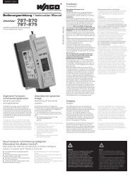
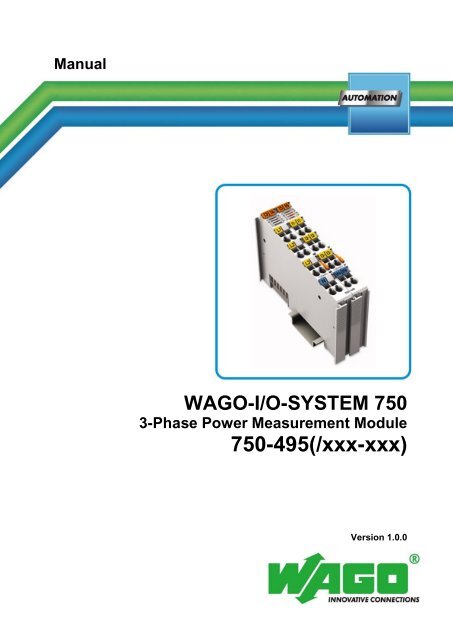
WAGO-I/O-SYSTEM 750<br />
3-Phase Power Measurement Module<br />
750-495(/xxx-xxx)<br />
Version 1.0.0
=== Ende der Liste für T extmar ke Ei nband_vorne ===<br />
2 WAGO-I/O-SYSTEM 750<br />
750-495 3-Phase Power Measurement Module<br />
© 2013 by WAGO Kontakttechnik GmbH & Co. KG<br />
All rights reserved.<br />
WAGO Kontakttechnik GmbH & Co. KG<br />
Hansastraße 27<br />
D-32423 Minden<br />
Phone: +49 (0) 571/8 87 – 0<br />
Fax: +49 (0) 571/8 87 – 1 69<br />
E-Mail:<br />
Web:<br />
info@wago.com<br />
http://www.wago.com<br />
Technical Support<br />
Phone: +49 (0) 571/8 87 – 5 55<br />
Fax: +49 (0) 571/8 87 – 85 55<br />
E-Mail:<br />
support@wago.com<br />
Every conceivable measure has been taken to ensure the accuracy and<br />
completeness of this documentation. However, as errors can never be fully<br />
excluded, we always appreciate any information or suggestions for improving the<br />
documentation.<br />
E-Mail:<br />
documentation@wago.com<br />
We wish to point out that the software and hardware terms as well as the<br />
trademarks of companies used and/or mentioned in the present manual are<br />
generally protected by trademark or patent.<br />
Manual<br />
Version 1.0.0
WAGO-I/O-SYSTEM 750 Table of Contents 3<br />
750-495 3-Phase Power Measurement Module<br />
Pos : 5 /D okumentati on allgemein/Verzeic hnisse/Inhalts verz eichnis - Ü berschrift oG und Verzei chnis @ 3\mod_1219151230875_21.docx @ 21063 @ @ 1<br />
Table of Contents<br />
Manual<br />
Version 1.0.0<br />
1 Notes about this Documentation ................................................................. 5<br />
1.1 Validity of this Documentation ................................................................. 5<br />
1.2 Revision History ........................................................................................ 5<br />
1.3 Copyright ................................................................................................... 5<br />
1.4 Symbols ..................................................................................................... 6<br />
1.5 Number Notation ....................................................................................... 7<br />
1.6 Font Conventions ...................................................................................... 7<br />
2 Important Notes ........................................................................................... 8<br />
2.1 Legal Bases ............................................................................................... 8<br />
2.1.1 Subject to Changes ............................................................................... 8<br />
2.1.2 Personnel Qualifications ....................................................................... 8<br />
2.1.3 Use of the 750 Series in Compliance with Underlying Provisions ...... 8<br />
2.1.4 Technical Condition of Specified Devices ........................................... 9<br />
2.2 Safety Advice (Precautions)...................................................................... 9<br />
3 Device Description ..................................................................................... 12<br />
3.1 View ........................................................................................................ 13<br />
3.2 Connectors ............................................................................................... 14<br />
3.2.1 Data Contacts/Internal Bus ................................................................. 14<br />
3.2.2 Power Jumper Contacts/Field Supply ................................................ 14<br />
3.2.3 CAGE CLAMP ® Connectors ............................................................. 15<br />
3.3 Display Elements .................................................................................... 17<br />
3.4 Operating Elements ................................................................................. 17<br />
3.5 Schematic Diagram ................................................................................. 18<br />
3.6 Technical Data ........................................................................................ 21<br />
3.6.1 Dimensions and Weight ..................................................................... 21<br />
3.6.2 Voltage Supply ................................................................................... 21<br />
3.6.3 Measuring Inputs ................................................................................ 21<br />
3.6.4 Measured Values ................................................................................ 22<br />
3.6.5 Internal Bus Communication .............................................................. 23<br />
3.6.6 Connection Type ................................................................................ 23<br />
3.6.7 Climatic Environmental Conditions ................................................... 23<br />
3.7 Approvals ................................................................................................ 24<br />
3.8 Standards and Guidelines ........................................................................ 24<br />
4 Function Description ................................................................................. 25<br />
4.1 Measuring Principle ................................................................................ 25<br />
4.2 Measured Values ..................................................................................... 25<br />
4.3 Description of Measured Values ............................................................. 27<br />
4.4 Measuring Errors and Accuracy .............................................................. 33<br />
5 Process Image ............................................................................................. 36<br />
5.1 Overview of Process Data ....................................................................... 36<br />
5.2 Output Data ............................................................................................. 37<br />
5.2.1 Definition of Control Words .............................................................. 37<br />
5.2.2 Definition of Output Data Words ....................................................... 38<br />
5.3 Input Data ................................................................................................ 39<br />
5.3.1 Definition of Status Words ................................................................. 39
=== Ende der Liste für T extmar ke Verzeic hnis_vor ne ===<br />
4 Table of Contents WAGO-I/O-SYSTEM 750<br />
750-495 3-Phase Power Measurement Module<br />
5.3.2 Definition of Input Data Words .......................................................... 42<br />
5.4 Process Image Descriptions .................................................................... 46<br />
5.4.1 Collection AC Measured Values (010) .............................................. 47<br />
5.4.2 Collections for Harmonics Analysis (020, 021, 022) ......................... 48<br />
5.4.3 Building-up the Measured Values ...................................................... 50<br />
5.5 Collections of Measured Values ............................................................. 51<br />
5.5.1 Collection 010 – AC Measured Values .............................................. 51<br />
5.5.2 Collection 020 – Harmonics Analysis on L1 ..................................... 56<br />
5.5.3 Collection 021 – Harmonics Analysis on L2 ..................................... 57<br />
5.5.4 Collection 022 – Harmonics Analysis on L3 ..................................... 58<br />
5.6 Examples of Calculating the Measured Values from the Process Values59<br />
6 Mounting ..................................................................................................... 63<br />
6.1 Mounting Sequence ................................................................................. 63<br />
6.2 Inserting and Removing Devices ............................................................ 64<br />
6.2.1 Inserting I/O Module .......................................................................... 64<br />
6.2.2 Removing the I/O Module .................................................................. 65<br />
7 Connect Devices ......................................................................................... 66<br />
7.1 Connecting a Conductor to the CAGE CLAMP ® ................................... 66<br />
7.2 Voltage Measurement ............................................................................. 67<br />
7.3 Current Measurement .............................................................................. 68<br />
7.3.1 Current Measurement on a Motor ...................................................... 68<br />
7.3.2 Current Transformers ......................................................................... 69<br />
7.3.3 ‘Rogowski’ Coils ................................................................................ 71<br />
7.3.4 Additional Measuring Instruments in a Current Path ......................... 71<br />
7.4 Power Measurement ................................................................................ 72<br />
8 Commissioning ........................................................................................... 73<br />
8.1 Configuration with WAGO-I/O-CHECK ............................................... 74<br />
8.1.1 “Application“ Tab .............................................................................. 77<br />
8.1.2 "Phase L1”, “Phase L2”, “Phase L3” Tabs ........................................ 79<br />
8.1.3 “Neutral Conductor” Tab ................................................................... 81<br />
8.1.4 “I/O Module“ Tab............................................................................... 82<br />
8.1.5 “Energy“ Tab ...................................................................................... 85<br />
8.1.6 "Factory Settings" Tab ....................................................................... 87<br />
8.2 Displaying the Measured Values via WAGO-I/O-CHECK .................... 89<br />
9 Diagnostics .................................................................................................. 98<br />
10 Appendix ..................................................................................................... 99<br />
10.1 Examples of CSV Data Files ................................................................... 99<br />
10.1.1 Snapshot ............................................................................................. 99<br />
10.1.2 Measurement Recording ................................................................... 103<br />
10.2 Factory Settings ..................................................................................... 104<br />
10.3 Register Assignment ............................................................................. 106<br />
10.4 Parameter Assignment .......................................................................... 112<br />
List of Figures .................................................................................................... 119<br />
List of Tables ...................................................................................................... 120<br />
Manual<br />
Version 1.0.0
Pos : 8 /Alle Serien (Allgemeine M odul e)/Hinweise z ur Dokumentation/Hi nweis e/Hi nweis : D okumentation aufbewahr en @ 4\mod_1237987339812_21.docx @ 29026 @ @ 1<br />
WAGO-I/O-SYSTEM 750 Notes about this Documentation 5<br />
750-495 3-Phase Power Measurement Module<br />
Pos : 7 /Alle Serien (Allgemeine M odul e)/Übersc hriften für all e Serien/Hi nweis z ur Dokumentation/Hinweis e z ur D okumentation - Ü bersc hrift 1 @ 4\mod_1237987661750_21.docx @ 29029 @ 1 @ 1<br />
1 Notes about this Documentation<br />
Keep this documentation!<br />
The operating instructions are part of the product and shall be kept for the entire<br />
lifetime of the device. They shall be transferred to each subsequent owner or user<br />
of the device. Care must also be taken to ensure that any supplement to these<br />
instructions are included, if applicable.<br />
Pos : 9 /Alle Serien (Allgemeine M odul e)/Übersc hriften für all e Serien/Hi nweis z ur Dokumentation/Gültig keits ber eich - Übersc hrift 2 @ 12\mod_1338912448776_21.docx @ 96469 @ 2 @ 1<br />
1.1 Validity of this Documentation<br />
Pos : 10 /Serie 750 ( WAGO-I/O-SYST EM)/Hi nweis e z ur D okumentati on/Gültigkeits bereic h D okumentation Bus klemme 750- xxxx, Standardversion und aufgelistete Varianten @ 14\mod_1358944038682_21.docx @ 109354 @ @ 1<br />
This documentation is only applicable to the I/O module 750-495 (3-Phase Power<br />
Measurement Module) of the WAGO-I/O-SYSTEM 750 series and the variants<br />
listed in the table below.<br />
Pos : 11 /Serie 750 ( WAGO-I/O-SYST EM)/Hi nweis e z ur D okumentati on/Variantenlisten/Variantenliste - 750-495 - 1A, 5A und Rog.Spul e @ 16\mod_1376314702067_21.docx @ 128434 @ @ 1<br />
Table 1: Variants<br />
Item Number<br />
Description<br />
750-495 3-Phase Power Measurement Module 1 A<br />
750-495/000-001 3-Phase Power Measurement Module 5 A<br />
750-495/000-002 3-Phase Power Measurement Module R.C.<br />
Pos : 12 /Serie 750 ( WAGO-I/O-SYST EM)/Hi nweis e z ur D okumentati on/Hi nweise/Ac htung: Hinweis z ur D okumentati on Bus kl emmen 750- xxxx @ 4\mod_1237986979656_21.docx @ 29023 @ @ 1<br />
The I/O module 750-495 shall only be installed and operated according to the<br />
instructions in this manual and in the manual for the used fieldbus<br />
coupler/controller.<br />
Consider power layout of the WAGO-I/O-SYSTEM 750!<br />
In addition to these operating instructions, you will also need the manual for the<br />
used fieldbus coupler/controller, which can be downloaded at www.wago.com.<br />
There, you can obtain important information including information on electrical<br />
isolation, system power and supply specifications.<br />
Pos : 13 /All e Seri en (Allgemei ne Module)/Ü berschriften für alle Serien/Hinweis zur D okumentati on/Änderungs historie - Ü bers chrift 2 @ 6\mod_1255513312687_21.docx @ 42790 @ 2 @ 1<br />
1.2 Revision History<br />
Pos : 14 /Serie 750 ( WAGO-I/O-SYST EM)/Hi nweis e z ur D okumentati on/Änderungshis tori e/Änder ungs historie - 495 @ 16\mod_1376316664411_21.docx @ 128476 @ @ 1<br />
Table 2: Revision history<br />
Document Device version<br />
version<br />
Description of change<br />
Hardware Software<br />
1.0.0 01 01 First issue<br />
Pos : 15.1 /All e Seri en ( Allgemei ne Module)/Hi nweis e zur D okumentati on/Urhebersc hutz ausführlich @ 4\mod_1235565145234_21.docx @ 27691 @ 2 @ 1<br />
1.3 Copyright<br />
This Manual, including all figures and illustrations, is copyright-protected. Any<br />
further use of this Manual by third parties that violate pertinent copyright<br />
Manual<br />
Version 1.0.0
Pos : 15.4.1 /All e Serien ( Allgemei ne Module)/Wic htige Erläuterungen/Sicherheits- und sonstige Hinweise/Gefahr/Gefahr: _Warnung vor Personenschäden allgemein_ - Erl äuter ung @ 13\mod_1343309450020_21.docx @ 101029 @ @ 1<br />
Pos : 15.4.2 /All e Serien ( Allgemei ne Module)/Wic htige Erläuterungen/Sicherheits- und sons tige Hinweis e/Gefahr/Gefahr: _War nung vor Personenschäden durc h elektrisc hen Strom_ - Erläuterung @ 13\mod_1343309694914_21.docx @ 101030 @ @ 1<br />
Pos : 15.4.3 /All e Serien ( Allgemei ne Module)/Wic htige Erläuterungen/Sicherheits- und sonstige Hinweis e/Warnung/Warnung: _Warnung vor Personensc häden allgemei n_ - Erläuterung @ 13\mod_1343309877041_21.docx @ 101035 @ @ 1<br />
Pos : 15.4.4 /All e Serien ( Allgemei ne Module)/Wic htige Erläuterungen/Sicherheits- und sonstige Hinweis e/Vorsic ht/Vorsicht: _War nung vor Pers onensc häden allgemein_ - Erläuterung @ 13\mod_1343310028762_21.docx @ 101038 @ @ 1<br />
Pos : 15.4.5 /All e Serien ( Allgemei ne Module)/Wic htige Erläuterungen/Sicherheits- und sonstige Hinweise/Achtung/Achtung: _Warnung vor Sachschäden allgemein_ - Erläuterung @ 13\mod_1343310134623_21.docx @ 101041 @ @ 1<br />
Pos : 15.4.6 /All e Serien ( Allgemei ne Module)/Wic htige Erläuterungen/Sicherheits- und sonstige Hinweise/Achtung/Achtung: _Warnung vor Sachschäden durch elektrostatische Aufladung_ - Erläuterung @ 13\mod_1343310227702_21.docx @ 101044 @ @ 1<br />
Pos : 15.4.7 /All e Serien ( Allgemei ne Module)/Wic htige Erläuterungen/Sicherheits- und sonstige Hinweise/Hi nweis/Hinweis: _Wichtiger Hi nweis allgemein_ - Eräuterung @ 13\mod_1343310326906_21.docx @ 101047 @ @ 1<br />
6 Notes about this Documentation WAGO-I/O-SYSTEM 750<br />
750-495 3-Phase Power Measurement Module<br />
provisions is prohibited. Reproduction, translation, electronic and phototechnical<br />
filing/archiving (e.g., photocopying) as well as any amendments require the<br />
written consent of WAGO Kontakttechnik GmbH & Co. KG, Minden, Germany.<br />
Non-observance will involve the right to assert damage claims.<br />
Pos: 15.2 /Dokumentation allgemein/Gliederungselemente/---Seitenwechs el--- @ 3\mod_1221108045078_0.docx @ 21810 @ @ 1<br />
Pos : 15.3 /All e Seri en ( Allgemei ne Module)/Ü bers chriften für alle Serien/Hinweis z ur D okumentati on/Symbole - Ü berschrift 2 @ 13\mod_1351068042408_21.docx @ 105270 @ 2 @ 1<br />
1.4 Symbols<br />
Personal Injury!<br />
Indicates a high-risk, imminently hazardous situation which, if not avoided, will<br />
result in death or serious injury.<br />
Personal Injury Caused by Electric Current!<br />
Indicates a high-risk, imminently hazardous situation which, if not avoided, will<br />
result in death or serious injury.<br />
Personal Injury!<br />
Indicates a moderate-risk, potentially hazardous situation which, if not avoided,<br />
could result in death or serious injury.<br />
Personal Injury!<br />
Indicates a low-risk, potentially hazardous situation which, if not avoided, may<br />
result in minor or moderate injury.<br />
Damage to Property!<br />
Indicates a potentially hazardous situation which, if not avoided, may result in<br />
damage to property.<br />
Damage to Property Caused by Electrostatic Discharge (ESD)!<br />
Indicates a potentially hazardous situation which, if not avoided, may result in<br />
damage to property.<br />
Manual<br />
Version 1.0.0
Pos : 15.4.8 /All e Serien ( Allgemei ne Module)/Wic htige Erläuterungen/Sicherheits- und sons tige Hinweis e/Infor mation/Infor mation: _Weiter e Infor mation allgemei n_ - Erl äuter ung @ 13\mod_1343310439814_21.docx @ 101051 @ @ 1<br />
Pos : 16 /D okumentation allgemei n/Glieder ungs elemente/---Seitenwechs el--- @ 3\mod_1221108045078_0.doc x @ 21810 @ @ 1<br />
WAGO-I/O-SYSTEM 750 Notes about this Documentation 7<br />
750-495 3-Phase Power Measurement Module<br />
Important Note!<br />
Indicates a potential malfunction which, if not avoided, however, will not result in<br />
damage to property.<br />
Additional Information:<br />
Refers to additional information which is not an integral part of this<br />
documentation (e.g., the Internet).<br />
Pos: 15.5 /Dokumentation allgemein/Gliederungselemente/---Seitenwechs el--- @ 3\mod_1221108045078_0.docx @ 21810 @ @ 1<br />
Pos : 15.6 /All e Seri en ( Allgemei ne Module)/Hi nweis e zur D okumentati on/Zahlens ysteme @ 3\mod_1221059454015_21.docx @ 21711 @ 2 @ 1<br />
1.5 Number Notation<br />
Table 3: Number notation<br />
Number code Example Note<br />
Decimal 100 Normal notation<br />
Hexadecimal 0x64 C notation<br />
Binary<br />
'100'<br />
'0110.0100'<br />
In quotation marks, nibble separated with<br />
dots (.)<br />
Pos : 15.7 /All e Seri en ( Allgemei ne Module)/Hi nweis e zur D okumentati on/Sc hriftkonventi onen @ 3\mod_1221059521437_21.docx @ 21714 @ 2 @ 1<br />
1.6 Font Conventions<br />
Table 4: Font conventions<br />
Font type Indicates<br />
italic Names of paths and data files are marked in italic-type.<br />
e.g.: C:\Programme\WAGO-I/O-CHECK<br />
Menu Menu items are marked in bold letters.<br />
e.g.: Save<br />
> A greater-than sign between two names means the selection of a<br />
menu item from a menu.<br />
e.g.: File > New<br />
Input Designation of input or optional fields are marked in bold letters,<br />
e.g.: Start of measurement range<br />
“Value” Input or selective values are marked in inverted commas.<br />
e.g.: Enter the value “4 mA” under Start of measurement range.<br />
[Button] Pushbuttons in dialog boxes are marked with bold letters in square<br />
brackets.<br />
e.g.: [Input]<br />
[Key] Keys are marked with bold letters in square brackets.<br />
e.g.: [F5]<br />
Manual<br />
Version 1.0.0
8 Important Notes WAGO-I/O-SYSTEM 750<br />
750-495 3-Phase Power Measurement Module<br />
Pos : 17 /All e Seri en (Allgemei ne Module)/Ü berschriften für alle Serien/Wichtige Erläuterungen/Wichtige Erläuter ungen - Übersc hrift 1 @ 4\mod_1241428899156_21.docx @ 32170 @ 1 @ 1<br />
2 Important Notes<br />
Pos : 18.1 /All e Seri en ( Allgemei ne Dokumente) ( Allgemei ne Module)/Wic htige Erläuterungen/Einl eitung Wic htige Erläuterungen @ 3\mod_1221059818031_21.docx @ 21717 @ @ 1<br />
This section includes an overall summary of the most important safety<br />
requirements and notes that are mentioned in each individual section. To protect<br />
your health and prevent damage to devices as well, it is imperative to read and<br />
carefully follow the safety guidelines.<br />
Pos : 18.2 /All e Seri en ( Allgemei ne Module)/Ü bers chriften für alle Serien/Wichtige Erläuter ungen/Rechtliche Gr undl agen - Ü bersc hrift 2 @ 3\mod_1221060626343_21.docx @ 21726 @ 2 @ 1<br />
2.1 Legal Bases<br />
Pos: 18.3 /Alle Serien (Allgemeine Dokumente) (Allgemeine Module)/Wichtige Erläuterungen/Änderungsvorbehalt - Ü bers chrift 3 und Inhalt @ 3\mod_1221060036484_21.docx @ 21720 @ 3 @ 1<br />
2.1.1 Subject to Changes<br />
WAGO Kontakttechnik GmbH & Co. KG reserves the right to provide for any<br />
alterations or modifications that serve to increase the efficiency of technical<br />
progress. WAGO Kontakttechnik GmbH & Co. KG owns all rights arising from<br />
the granting of patents or from the legal protection of utility patents. Third-party<br />
products are always mentioned without any reference to patent rights. Thus, the<br />
existence of such rights cannot be excluded.<br />
Pos: 18.4 /Serie 750 (WAGO-I/O-SYST EM)/Wic htige Erläuterungen/Pers onalqualifi kation 750- xxxx @ 3\mod_1224061208046_21.docx @ 24063 @ 3 @ 1<br />
2.1.2 Personnel Qualifications<br />
All sequences implemented on Series 750 devices may only be carried out by<br />
electrical specialists with sufficient knowledge in automation. The specialists<br />
must be familiar with the current norms and guidelines for the devices and<br />
automated environments.<br />
All changes to the coupler or controller should always be carried out by qualified<br />
personnel with sufficient skills in PLC programming.<br />
Pos: 18.5 /Serie 750 (WAGO-I/O-SYST EM)/Wic htige Erläuterungen/Bes timmungsgemäß e Verwendung 750- xxxx @ 3\mod_1224064151234_21.docx @ 24070 @ 3 @ 1<br />
2.1.3 Use of the 750 Series in Compliance with Underlying<br />
Provisions<br />
Couplers, controllers and I/O modules found in the modular WAGO-I/O-<br />
SYSTEM 750 receive digital and analog signals from sensors and transmit them<br />
to the actuators or higher-level control systems. Using programmable controllers,<br />
the signals can also be (pre-) processed.<br />
The components have been developed for use in an environment that meets the<br />
IP20 protection class criteria. Protection against finger injury and solid impurities<br />
up to 12.5 mm diameter is assured; protection against water damage is not<br />
ensured. Unless otherwise specified, operation of the components in wet and<br />
dusty environments is prohibited.<br />
Operating 750 Series components in home applications without further measures<br />
is only permitted if they meet the emission limits (emissions of interference)<br />
according to EN 61000-6-3. You will find the relevant information in the section<br />
on "WAGO-I/O-SYSTEM 750" "System Description" "Technical Data" in<br />
the manual for the used fieldbus coupler/controller.<br />
Manual<br />
Version 1.0.0
Pos : 18.10 /Serie 750 ( WAGO-I/O-SYST EM)/Wichtig e Erl äuter ung en/Sic her hei ts- und s onstige Hinweise/Gefahr/Gefahr: Berührungssc hutz vorsehen 750-0493/0494/Gefahr: Ber ühr ungss chutz vors ehen 750- 0493/0494/0495 @ 15\mod_1366120208015_21.docx @ 117160 @ @ 1<br />
Pos: 18.11.1 /Alle Serien (Allgemeine Dokumente) (Allgemeine M odul e)/Wichtige Erläuter ungen/Sic herheits hinweise/Gefahr /Gefahr: Nicht an Geräten unter Spannung ar beiten! @ 6\mod_1260180365327_21.docx @ 46727 @ @ 1<br />
Pos : 18.11.2 /Serie 750 ( WAGO-I/O- SYST EM)/Wic htig e Erl äuter ung en/Sic her hei ts- und s onstige Hi nweise/Gefahr/Gefahr: Ei nbau 0750- xxxx nur i n Gehäus en, Sc hränken oder el ektrisc hen Betriebsräumen! @ 6\mod_1260180556692_21.docx @ 46731 @ @ 1<br />
Pos : 18.11.3 /Alle Serien (Allgemeine D okumente) (Allgemeine M odul e)/Wichtige Erläuter ungen/Sic herheits hinweise/Gefahr /Gefahr: Unfall verhütungsvorsc hriften beachten! @ 6\mod_1260180657000_21.docx @ 46735 @ @ 1<br />
Pos : 18.11.4 /Alle Serien (Allgemeine D okumente) (Allgemeine M odul e)/Wichtige Erläuter ungen/Sic herheits hinweise/Gefahr /Gefahr: Auf normg erec hten Ansc hluss ac hten! @ 6\mod_1260180753479_21.docx @ 46739 @ @ 1<br />
Pos : 18.12 /Serie 750 ( WAGO-I/O-SYST EM)/Wichtig e Erl äuter ung en/Sic her hei ts- und s onstige Hinweise/Ac htung/Ac htung: Kein dauer hafter Ei ngangsstrom über 1A bz w.5A 750-0493/0494/Achtung: Kein Eing angsstrom über 1A bzw.5A, 750-0493/0494/0495 @ 15\mod_1366120670473_21.docx @ 117163 @ @ 1<br />
WAGO-I/O-SYSTEM 750 Important Notes 9<br />
750-495 3-Phase Power Measurement Module<br />
Appropriate housing (per 94/9/EG) is required when operating the WAGO-I/O-<br />
SYSTEM 750 in hazardous environments. Please note that a prototype test<br />
certificate must be obtained that confirms the correct installation of the system in<br />
a housing or switch cabinet.<br />
Pos: 18.6 /Alle Serien (Allgemeine Dokumente) (Allgemeine Module)/Wichtige Erläuterungen/T ec hnis cher Z ustand der Geräte - Übersc hrift 3 und Inhalt @ 3\mod_1221060446109_21.docx @ 21723 @ 3 @ 1<br />
2.1.4 Technical Condition of Specified Devices<br />
The components to be supplied Ex Works, are equipped with hardware and<br />
software configurations, which meet the individual application requirements.<br />
WAGO Kontakttechnik GmbH & Co. KG will be exempted from any liability in<br />
case of changes in hardware or software as well as to non-compliant usage of<br />
components.<br />
Please send your request for modified and new hardware or software<br />
configurations directly to WAGO Kontakttechnik GmbH & Co. KG.<br />
Pos: 18.7 /Dokumentation allgemein/Gliederungselemente/---Seitenwechs el--- @ 3\mod_1221108045078_0.docx @ 21810 @ @ 1<br />
Pos : 18.8 /All e Seri en ( Allgemei ne Module)/Ü bers chriften für alle Serien/Wichtige Erläuter ungen/Sic herheits hinweise - Übersc hrift 2 @ 6\mod_1260180299987_21.docx @ 46724 @ 2 @ 1<br />
2.2 Safety Advice (Precautions)<br />
Pos : 18.9 /All e Seri en ( Allgemei ne Dokumente) ( Allgemei ne Module)/Wic htige Erläuterungen/Sicherheits hi nweis e/Einl eitung Sicherheits hinweis e H ardware @ 6\mod_1260180170493_21.docx @ 46720 @ @ 1<br />
For installing and operating purposes of the relevant device to your system the<br />
following safety precautions shall be observed:<br />
Install protection against electric shock!<br />
All wiring for the measurement system shall be provided with protection against<br />
shock hazard voltages along with the corresponding safety signs!<br />
Do not work on components while energized!<br />
All power sources to the device shall be switched off prior to performing any<br />
installation, repair or maintenance work.<br />
Installation only in appropriate housings, cabinets or in electrical operation<br />
rooms!<br />
The WAGO-I/O-SYSTEM 750 and its components are an open system. As such,<br />
install the system and its components exclusively in appropriate housings,<br />
cabinets or in electrical operation rooms. Allow access to such equipment and<br />
fixtures to authorized, qualified staff only by means of specific keys or tools.<br />
Manual<br />
Version 1.0.0
Pos : 18.13.1 /Alle Serien (Allgemeine D okumente) (Allgemeine M odul e)/Wichtige Erläuter ungen/Sic herheits hinweise/Ac htung/Ac htung: Defekte oder besc hädigte Ger äte aus tausc hen! @ 6\mod_1260180857358_21.docx @ 46743 @ @ 1<br />
Pos : 18.13.2 /Alle Serien (Allgemeine D okumente) (Allgemeine M odul e)/Wichtige Erläuter ungen/Sic herheits hinweise/Ac htung/Ac htung: Geräte vor kriec henden und is olier enden Stoffen schützen! @ 6\mod_1260181036216_21.docx @ 46747 @ @ 1<br />
Pos : 18.13.3 /Alle Serien (Allgemeine D okumente) (Allgemeine M odul e)/Wichtige Erläuter ungen/Sic herheits hinweise/Ac htung/Ac htung: Rei nigung nur mit zul ässigen M aterialien! @ 6\mod_1260181203293_21.docx @ 46751 @ @ 1<br />
Pos : 18.13.4 /Alle Serien (Allgemeine D okumente) (Allgemeine M odul e)/Wichtige Erläuter ungen/Sic herheits hinweise/Ac htung/Ac htung: Kei n Kontakts pray verwenden! @ 6\mod_1260181290808_21.docx @ 46755 @ @ 1<br />
Pos : 18.13.5 /Alle Serien (Allgemeine D okumente) (Allgemeine M odul e)/Wichtige Erläuter ungen/Sic herheits hinweise/Ac htung/Ac htung: Verpol ung ver mei den! @ 6\mod_1260184045744_21.docx @ 46767 @ @ 1<br />
Pos : 18.13.6 /Alle Serien (Allgemeine D okumente) (Allgemeine M odul e)/Wichtige Erläuter ungen/Sic herheits hinweise/Ac htung/Ac htung: El ektr ostatisc he Entl adung vermeiden! @ 6\mod_1260181364729_21.docx @ 46759 @ @ 1<br />
10 Important Notes WAGO-I/O-SYSTEM 750<br />
750-495 3-Phase Power Measurement Module<br />
Note the max. continuous measuring current of 1 A resp. 5 A!<br />
The max. continuous measuring current of the module is 1 A resp. 5 A. If the<br />
used current transformers allow greater secondary currents than 1 A resp. 5 A<br />
install additional transformers with an appropriate transforming ratio!<br />
Replace defective or damaged devices!<br />
Replace defective or damaged device/module (e.g., in the event of deformed<br />
contacts), since the long-term functionality of device/module involved can no<br />
longer be ensured.<br />
Protect the components against materials having seeping and insulating<br />
properties!<br />
The components are not resistant to materials having seeping and insulating<br />
properties such as: aerosols, silicones and triglycerides (found in some hand<br />
creams). If you cannot exclude that such materials will appear in the component<br />
environment, then install the components in an enclosure being resistant to the<br />
above-mentioned materials. Clean tools and materials are imperative for handling<br />
devices/modules.<br />
Cleaning only with permitted materials!<br />
Clean soiled contacts using oil-free compressed air or with ethyl alcohol and<br />
leather cloths.<br />
Do not use any contact spray!<br />
Do not use any contact spray. The spray may impair contact area functionality in<br />
connection with contamination.<br />
Do not reverse the polarity of connection lines!<br />
Avoid reverse polarity of data and power supply lines, as this may damage the<br />
devices involved.<br />
Manual<br />
Version 1.0.0
Pos : 19 /D okumentation allgemei n/Glieder ungs elemente/---Seitenwechs el--- @ 3\mod_1221108045078_0.docx @ 21810 @ @ 1<br />
WAGO-I/O-SYSTEM 750 Important Notes 11<br />
750-495 3-Phase Power Measurement Module<br />
Avoid electrostatic discharge!<br />
The devices are equipped with electronic components that you may destroy by<br />
electrostatic discharge when you touch. Pay attention while handling the devices<br />
to good grounding of the environment (persons, job and packing).<br />
Manual<br />
Version 1.0.0
Pos : 22 /D okumentation allgemei n/Glieder ungs elemente/---Seitenwechs el--- @ 3\mod_1221108045078_0.docx @ 21810 @ @ 1<br />
12 Device Description WAGO-I/O-SYSTEM 750<br />
750-495 3-Phase Power Measurement Module<br />
Pos : 20 /All e Seri en (Allgemei ne Module)/Ü berschriften für alle Serien/Gerätebesc hreibung/Gerätebeschreibung - Übersc hrift 1 @ 3\mod_1233756084656_21.docx @ 27096 @ 1 @ 1<br />
3 Device Description<br />
Pos : 21 /Serie 750 ( WAGO-I/O-SYST EM)/Ger ätebesc hrei bung/Ei nlei tung/Analogei ngangs klemmen/Gerätebeschr eibung - Ei nleitung 750- 0495 @ 16\mod_1376321299425_21.docx @ 128508 @ @ 1<br />
The 3-Phase Power Measurement Module (also called I/O Module) measures the<br />
electrical data in a 3-phase supply network.<br />
The 3 phase voltages are measured via connection to L1, L2, L3 and N. The<br />
currents are fed to I1+ and I1−, I2+ and I2−, I3+ and I3−, IN+ and IN− via current<br />
transformers resp. via ‘Rogowski’ coils to RC1+ and RC1−, RC2+ and RC2−,<br />
RC3+ and RC3−, RCN+ and RCN−. Based on these input signals the I/O module<br />
calculates numerous AC values like voltages, currents, powers (active, reactive<br />
and apparent), energies, power factors, phase shift angles and frequencies.<br />
Furthermore, an analysis of harmonic waves is carried out up to the 41 st harmonic.<br />
The measured values are available in the process image. Therefore, no high<br />
computing power is required from the higher-level controller.<br />
The calculated values indicate whether the load is inductive or capacitive and<br />
whether it consumes or generates energy. For this purpose a 4-quadrant display is<br />
incorporated in WAGO-I/O-CHECK.<br />
The I/O module provides a great number of measured values for a comprehensive<br />
supply network analysis via the fieldbus. By means of the measured values the<br />
operator can regulate the supply to a drive or machine in the best possible way<br />
and protect the installation from damage/failure.<br />
The I/O module 750-495 measures currents up to 1 A, 750-495/000-001 measures<br />
currents up to 5 A and 750-495/000-002 measures currents via ‘Rogowski’ coils<br />
RT500 up to 500 A or via RT2000 up to 2000 A.<br />
Manual<br />
Version 1.0.0
Pos : 24 /Serie 750 ( WAGO-I/O-SYST EM)/Ger ätebesc hrei bung/Ansic ht/Anal ogei ngangskl emmen/Ansicht 750-0495 @ 16\mod_1376316917249_21.docx @ 128480 @ @ 1<br />
Pos : 26 /D okumentation allgemei n/Glieder ungs elemente/---Seitenwechs el--- @ 3\mod_1221108045078_0.docx @ 21810 @ @ 1<br />
WAGO-I/O-SYSTEM 750 Device Description 13<br />
750-495 3-Phase Power Measurement Module<br />
Pos : 23 /All e Seri en (Allgemei ne Module)/Ü berschriften für alle Serien/Gerätebesc hreibung/Ansic ht - Ü berschrift 2 @ 4\mod_1240984217343_21.docx @ 31958 @ 2 @ 1<br />
3.1 View<br />
Figure 1: View of 750-495 and 750-495/000-001 (left) and 750-495/000-002 (right)<br />
Pos : 25 /Serie 750 ( WAGO-I/O-SYST EM)/Ger ätebesc hrei bung/Ansic ht/Ansic ht C ageCl amp® _Leg ende mit LED s_ohne Leis tungs kontakte @ 16\mod_1371816091053_21.docx @ 124052 @ @ 1<br />
Table 5: Caption acc. to figure “View”<br />
Pos. Description<br />
Details see section<br />
1 Marking possibility with ---<br />
Mini-WSB<br />
2 Status LEDs “Device Description” > “Display Elements”<br />
3 Data contacts “Device Description” > ”Connectors”<br />
4 CAGE CLAMP ® supplies “Device Description” > ”Connectors”<br />
5 Release tab “Mounting” > ”Inserting and Removing<br />
Devices”<br />
Manual<br />
Version 1.0.0
Pos: 29.2 /Serie 750 (WAGO-I/O-SYST EM)/Wic htige Erläuterungen/Sicherheits- und sonstig e Hinweis e/Achtung/Achtung: Bus kl emmen nic ht auf Goldfeder kontakte leg en! @ 7\mod_1266318463636_21.docx @ 50695 @ @ 1<br />
Pos: 29.3 /Serie 750 (WAGO-I/O-SYST EM)/Wic htige Erläuterungen/Sicherheits- und sonstige Hinweise/Achtung/Achtung: ESD - Auf g ute Erdung der U mgebung ac hten! @ 7\mod_1266318538667_21.docx @ 50708 @ @ 1<br />
Pos : 32 /D okumentation allgemei n/Glieder ungs elemente/---Seitenwechs el--- @ 3\mod_1221108045078_0.docx @ 21810 @ @ 1<br />
14 Device Description WAGO-I/O-SYSTEM 750<br />
750-495 3-Phase Power Measurement Module<br />
Pos : 27 /All e Seri en (Allgemei ne Module)/Ü berschriften für alle Serien/Gerätebesc hreibung/Ansc hlüsse - Übersc hrift 2 @ 4\mod_1240984262656_21.docx @ 31961 @ 2 @ 1<br />
3.2 Connectors<br />
Pos : 28 /Serie 750 ( WAGO-I/O-SYST EM)/Ger ätebesc hrei bung/Ansc hl üss e/Datenkontakte/Kl emmenbus - Ü bersc hrift 3 @ 6\mod_1256294684083_21.docx @ 43660 @ 3 @ 1<br />
3.2.1 Data Contacts/Internal Bus<br />
Pos : 29.1 /Serie 750 (WAGO-I/O-SYST EM)/Ger ätebesc hrei bung/Ansc hl üsse/Datenkontakte - F eldbus koppler/-c ontroll er, Abbildung und Besc hrei bung @ 3\mod_1231771259187_21.docx @ 26002 @ @ 1<br />
Communication between the coupler/controller and the I/O modules as well as the<br />
system supply of the I/O modules is carried out via the internal bus. It is<br />
comprised of 6 data contacts, which are available as self-cleaning gold spring<br />
contacts.<br />
Figure 2: Data contacts<br />
Do not place the I/O modules on the gold spring contacts!<br />
Do not place the I/O modules on the gold spring contacts in order to avoid soiling<br />
or scratching!<br />
Ensure that the environment is well grounded!<br />
The modules are equipped with electronic components that may be destroyed by<br />
electrostatic discharge. When handling the modules, ensure that the environment<br />
(persons, workplace and packing) is well grounded. Avoid touching conductive<br />
components, e.g. data contacts.<br />
Pos : 30 /Serie 750 ( WAGO-I/O-SYST EM)/Ger ätebesc hrei bung/Ansc hl üss e/Leistungs kontakte/F el dvers orgung - Übersc hrift 3 @ 6\mod_1256294692864_21.docx @ 43664 @ 3 @ 1<br />
3.2.2 Power Jumper Contacts/Field Supply<br />
Pos : 31 /Serie 750 ( WAGO-I/O-SYST EM)/Ger ätebesc hrei bung/Ansc hl üss e/Leistungs kontakte nic ht vorhanden @ 8\mod_1281073936319_21.docx @ 62530 @ @ 1<br />
The I/O module 750-495 has no power jumper contacts.<br />
Manual<br />
Version 1.0.0
WAGO-I/O-SYSTEM 750 Device Description 15<br />
750-495 3-Phase Power Measurement Module<br />
Pos : 33 /Serie 750 ( WAGO-I/O-SYST EM)/Ger ätebesc hrei bung/Ansc hl üss e/CAGE CLAMP- Anschl üss e - Ü berschrift 3 @ 6\mod_1256296337770_21.docx @ 43674 @ 3 @ 1<br />
3.2.3 CAGE CLAMP ® Connectors<br />
Pos : 34 /Serie 750 ( WAGO-I/O-SYST EM)/Ger ätebesc hrei bung/Ansc hl üss e/Analogei ngangs klemmen/Ansc hlüsse 750-0495 C AGE C LAM P @ 16\mod_1376319713900_21.docx @ 128499 @ @ 1<br />
12 CAGE CLAMP ® connectors make up the measuring inputs. The 3-phase<br />
supply network and the loads/generators are clamped here. See also section<br />
„Connect Devices“.<br />
Three connectors each form the measuring channels:<br />
• Channel 1: L1, I1+ and I1− (voltage and current of phase L1)<br />
• Channel 2: L2, I2+ and I2− (voltage and current of phase L2)<br />
• Channel 3: L3, I3+ and I3− (voltage and current of phase L3)<br />
• Channel 4: IN+ and IN− (current of neutral conductor)<br />
Figure 3: CAGE CLAMP ® connectors 750-495 and 750-495/000-001<br />
Table 6: CAGE CLAMP ® connectors 750-495 and 750-495/000-001<br />
Connector<br />
L1<br />
L2<br />
L3<br />
N<br />
I1+ and I1− Current L1<br />
I2+ and I2− Current L2<br />
I3+ and I3− Current L3<br />
IN+ and IN− Current N<br />
Function<br />
Voltage L1<br />
Voltage L2<br />
Voltage L3<br />
Neutral conductor<br />
(reference for all measurements)<br />
Manual<br />
Version 1.0.0
Pos : 35 /D okumentation allgemei n/Glieder ungs elemente/---Seitenwechs el--- @ 3\mod_1221108045078_0.docx @ 21810 @ @ 1<br />
16 Device Description WAGO-I/O-SYSTEM 750<br />
750-495 3-Phase Power Measurement Module<br />
Figure 4: CAGE CLAMP ® connectors 750-495/000-002<br />
Table 7: CAGE CLAMP ® connectors 750-495/000-002<br />
Connector Function<br />
L1<br />
Voltage L1<br />
L2<br />
Voltage L2<br />
L3<br />
Voltage L3<br />
N<br />
Neutral conductor<br />
(reference for all measurements)<br />
RC1+ and RC1− Current L1 via ‘Rogowski coil’<br />
RC2+ and RC2− Current L2 via ‘Rogowski coil’<br />
RC3+ and RC3− Current L3 via ‘Rogowski coil’<br />
RCN+ and RCN− Current N via ‘Rogowski coil’<br />
Manual<br />
Version 1.0.0
Pos : 40 /D okumentation allgemei n/Glieder ungs elemente/---Seitenwechs el--- @ 3\mod_1221108045078_0.docx @ 21810 @ @ 1<br />
WAGO-I/O-SYSTEM 750 Device Description 17<br />
750-495 3-Phase Power Measurement Module<br />
Pos : 36 /All e Seri en (Allgemei ne Module)/Ü berschriften für alle Serien/Gerätebesc hreibung/Anz eigeel emente - Übersc hrift 2 @ 4\mod_1240984390875_21.docx @ 31964 @ 2 @ 1<br />
3.3 Display Elements<br />
Pos : 37 /Serie 750 ( WAGO-I/O-SYST EM)/Ger ätebesc hrei bung/Anz eigeelemente/Anal ogei ngangs klemmen/Anz eigeel emente 750- 0494, - 0495 @ 16\mod_1371738731125_21.doc x @ 123880 @ @ 1<br />
LED A indicates the operating status, LEDs B … H indicate possible errors.<br />
Figure 5: LED-indicators<br />
The meaning of these indications is as follows:<br />
LED A<br />
LED B<br />
LED C<br />
LED D<br />
LED E<br />
LED F<br />
LED G<br />
LED H<br />
Status Message<br />
No operational readiness or<br />
the internal data bus communication is interrupted.<br />
Off Note: If the watchdog was disabled, the LED is always<br />
green. See section “Commissioning” > “Configuration<br />
with WAGO-I/O-CHECK“.<br />
Green<br />
Operational readiness and correct internal data bus<br />
communication<br />
Off No error<br />
Red<br />
General error message for L1:<br />
Under-/overvoltage or overcurrent<br />
Off No error<br />
Red<br />
General error message: Clipping of a current measuring<br />
path IL1, IL2 or IL3<br />
Off No error<br />
Red<br />
High measuring error, caused by undershooting the min.<br />
voltage at L1, L2 or L3<br />
Off No error<br />
Red<br />
General error message for L2:<br />
Under-/overvoltage or overcurrent<br />
Off No error<br />
Red<br />
General error message for L3:<br />
Under-/overvoltage or overcurrent<br />
Off No error<br />
Red<br />
General error message: Clipping of a voltage measuring<br />
path L1, L2 or L3<br />
Off No error<br />
Yellow Error of the phase sequence L1-L2-L3<br />
Pos : 38 /All e Seri en (Allgemei ne Module)/Ü berschriften für alle Serien/Gerätebesc hreibung/Bedienel emente - Ü berschrift 2 @ 4\mod_1239191655456_21.docx @ 30439 @ 2 @ 1<br />
3.4 Operating Elements<br />
Pos : 39 /Serie 750 ( WAGO-I/O-SYST EM)/Ger ätebesc hrei bung/Bedienel emente/Bedi enel emente Bus kl emme 750- xxxx nic ht vor handen @ 4\mod_1236322031125_21.docx @ 28063 @ @ 1<br />
The I/O module 750-495 has no operating elements.<br />
Manual<br />
Version 1.0.0
Pos : 42 /Serie 750 ( WAGO-I/O-SYST EM)/Ger ätebesc hrei bung/Schematisc he Sc haltbil der/Anal ogeing angs kl emmen/Sc hematisc hes Sc haltbild 750-0495 @ 16\mod_1376382441894_21.docx @ 128560 @ @ 1<br />
18 Device Description WAGO-I/O-SYSTEM 750<br />
750-495 3-Phase Power Measurement Module<br />
Pos : 41 /All e Seri en (Allgemei ne Module)/Ü berschriften für alle Serien/Gerätebesc hreibung/Sc hematisches Sc haltbil d - Ü bersc hrift 2 @ 4\mod_1240984441312_21.docx @ 31967 @ 2 @ 1<br />
3.5 Schematic Diagram<br />
Figure 6: Schematic circuit diagram for 750-495 and 750-495/000-001<br />
Manual<br />
Version 1.0.0
WAGO-I/O-SYSTEM 750 Device Description 19<br />
750-495 3-Phase Power Measurement Module<br />
Figure 7: Schematic circuit diagram for 750-495/000-002<br />
Manual<br />
Version 1.0.0
Pos : 43 /D okumentation allgemei n/Glieder ungs elemente/---Seitenwechs el--- @ 3\mod_1221108045078_0.docx @ 21810 @ @ 1<br />
20 Device Description WAGO-I/O-SYSTEM 750<br />
750-495 3-Phase Power Measurement Module<br />
Function Earth FE!<br />
In order to get a function earth, the connection N is connected to the mounting rail<br />
via a 1 nF capacitor and a spring contact. If the rail is correctly connected to PE,<br />
the immunity to interference is increased.<br />
The 3 voltage measuring paths are not isolated from the 4 current measuring<br />
paths!<br />
The connection N forms the internal reference for all electrical measurements.<br />
Potential differences between N and the current inputs may result in measurement<br />
errors or even destruction of the I/O module!<br />
Do not connect the current inputs to PE!<br />
Manual<br />
Version 1.0.0
WAGO-I/O-SYSTEM 750 Device Description 21<br />
750-495 3-Phase Power Measurement Module<br />
Pos : 44 /All e Seri en (Allgemei ne Module)/Ü berschriften für alle Serien/Gerätebesc hreibung/Technisc he Daten - Ü berschrift 2 @ 3\mod_1232967587687_21.docx @ 26924 @ 2 @ 1<br />
3.6 Technical Data<br />
Pos: 45.1 /Serie 750 (WAGO-I/O-SYST EM)/Ger ätebesc hrei bung/T echnisc he Daten/Anal ogeing angs kl emmen/T ec hnis che D aten 750-0495 @ 16\mod_1376382793919_21.docx @ 128564 @ 33333 @ 1<br />
3.6.1 Dimensions and Weight<br />
Table 8: Technical data ‒ dimensions and weight<br />
Width<br />
24 mm<br />
Height (from upper edge of carrier rail) 64 mm<br />
Length<br />
100 mm<br />
Weight<br />
88 g<br />
3.6.2 Voltage Supply<br />
Table 9: Technical data ‒ voltage supply<br />
Supply voltage for the internal<br />
electronics<br />
Current consumption max.<br />
5 V DC<br />
(system voltage via internal bus)<br />
100 mA<br />
3.6.3 Measuring Inputs<br />
Table 10: Technical data ‒ measuring inputs<br />
Number of inputs<br />
7 (3 voltage measuring inputs,<br />
4 differential current measuring inputs)<br />
Input voltage max.<br />
Phase-to-phase voltage Lx-Ly:<br />
690 VAC,<br />
phase voltage Lx-N: 400 VAC<br />
Input resistance typ. (voltage) 1429 kΩ<br />
Input current max. 1 A for 750-495,<br />
5 A for 750-495/000-001,<br />
via ‘Rogowski’ coil 500 / 2000 A for<br />
750-495/000-002<br />
Input resistance typ. (current) 22 mΩ for 750-495,<br />
5 mΩ for 750-495/000-001,<br />
44 kΩ for 750-495/000-002<br />
Frequency range<br />
- frequency of supply network 45 … 65 Hz<br />
- analysis of harmonics<br />
0 … 3300 Hz<br />
Max. frequency<br />
15.9 kHz<br />
Signal form<br />
Any periodic signal (considering the<br />
max. operating frequency)<br />
Category of overvoltage<br />
III<br />
Nominal voltage spike<br />
6 kV<br />
Degree of contamination 2<br />
Manual<br />
Version 1.0.0
22 Device Description WAGO-I/O-SYSTEM 750<br />
750-495 3-Phase Power Measurement Module<br />
3.6.4 Measured Values<br />
Table 11: Technical data ‒ measured values<br />
Measuring procedure<br />
Calculated values<br />
Calculation of true RMS for voltages<br />
and currents, sample rate 8 kHz<br />
synchronous on all 7 measuring inputs,<br />
24 bits resolution<br />
Phase-to-phase voltages, powers,<br />
energies, power factors, network<br />
frequencies, harmonics analysis up to<br />
the 41st harmonic<br />
Update cycle of process data<br />
- RMS voltage Lx - N 40 ms<br />
- Min./max. RMS voltage Lx - N 50 ms<br />
- RMS voltage Lx - Ly 340 ms<br />
- Arithmetic mean value voltage Lx - N To be set, 5 ... 900 s<br />
- Peak value voltage Lx - N 200 ms<br />
- RMS current Lx 40 ms<br />
- Min./max. RMS current Lx 50 ms<br />
- Arithmetic mean value current Lx To be set, 5 ... 900 s<br />
- Peak value current Lx 200 ms<br />
- RMS current N 40 ms<br />
- Active power Lx 40 ms<br />
- Min./max. active power Lx 50 ms<br />
- Reactive power Lx 340 ms<br />
- Apparent power Lx 40 ms<br />
- All energy values 400 ms<br />
- Supply network frequency Lx 280 ms<br />
- Min./max. supply network<br />
280 ms<br />
frequency Lx<br />
- Phase angle phi Lx 340 ms<br />
- Power factor cos phi Lx 340 ms<br />
- Power factor PF Lx 280 ms<br />
- Power factor LF Lx 280 ms<br />
- Harmonics analysis<br />
-- Current 260 ms<br />
-- Voltage 260 ms<br />
-- HD/THD current 260 ms<br />
-- HD/THD voltage 260 ms<br />
Measuring errors<br />
- AC voltage
Pos : 46 /D okumentation allgemei n/Glieder ungs elemente/---Seitenwechs el--- @ 3\mod_1221108045078_0.docx @ 21810 @ @ 1<br />
WAGO-I/O-SYSTEM 750 Device Description 23<br />
750-495 3-Phase Power Measurement Module<br />
- Harmonics measured values
Pos : 49 /All e Seri en (Allgemei ne Module)/Z ulassungen/Standardz ulassungen/C E (Konformi täts kennz eichnung) @ 3\mod_1224494777421_21.docx @ 24276 @ @ 1<br />
Pos : 50 /D okumentation allgemei n/Glieder ungs elemente/------Leerz eile------ @ 3\mod_1224662755687_0.docx @ 24460 @ @ 1<br />
Pos : 52 /All e Seri en (Allgemei ne Module)/Z ulassungen/Standardz ulassungen/cU Lus (U L508) @ 3\mod_1224055013140_0.docx @ 24020 @ @ 1<br />
Pos : 53 /All e Seri en (Allgemei ne Module)/Z ulassungen/Ex-Z ulass ungen/cU Lus /cU Lus (AN SI/ISA 12.12.01) Class I, Di v2 ABCD T4 @ 3\mod_1224054791812_0.docx @ 24014 @ @ 1<br />
Pos : 54 /D okumentation allgemei n/Glieder ungs elemente/------Leerz eile------ @ 3\mod_1224662755687_0.docx @ 24460 @ @ 1<br />
Pos : 59 /D okumentation allgemei n/Glieder ungs elemente/---Seitenwechs el--- @ 3\mod_1221108045078_0.docx @ 21810 @ @ 1<br />
24 Device Description WAGO-I/O-SYSTEM 750<br />
750-495 3-Phase Power Measurement Module<br />
Pos : 47 /All e Seri en (Allgemei ne Module)/Ü berschriften für alle Serien/Gerätebesc hreibung/Zul ass ungen - Übersc hrift 2 @ 3\mod_1224055364109_21.docx @ 24030 @ 2 @ 1<br />
3.7 Approvals<br />
Pos : 48 /Serie 750 ( WAGO-I/O-SYST EM)/Ger ätebesc hrei bung/Z ulass ungen/Allgemei n/Z ulass ungen Busklemme 750- xxxx Allgemein, Standardversi on und all e Vari anten - Einl eitung @ 3\mod_1233911570312_21.docx @ 27390 @ @ 1<br />
The following approvals have been granted to the basic version and all variations<br />
of 750-495 I/O modules:<br />
Conformity Marking<br />
Pos : 51 /Serie 750 ( WAGO-I/O-SYST EM)/Ger ätebesc hrei bung/Z ulass ungen/Allgemei n/Z ul. i n Vorbereitung Busklemme 750- xxxx Allgemein, Standardvers . und alle Varianten - Einl eitung @ 17\mod_1381307954994_21.docx @ 133910 @ @ 1<br />
The following approvals are pending for the basic version and all variants of 750-<br />
495 I/O modules:<br />
CUL US<br />
UL508<br />
CUL US ANSI/ISA 12.12.01<br />
Class I, Div2 ABCD T4<br />
Pos : 55 /All e Seri en (Allgemei ne Module)/Ü berschriften für alle Serien/Gerätebesc hreibung/Nor men und Ric htlini en - Übersc hrift 2 @ 4\mod_1242804031875_21.docx @ 33646 @ 2 @ 1<br />
3.8 Standards and Guidelines<br />
Pos : 56 /Serie 750 ( WAGO-I/O-SYST EM)/Ger ätebesc hrei bung/N ormen und Ric htlini en/Nor men und Ric htlini en Bus kl emme 750-xxxx, Stanar dversion und alle Varianten - Ei nleitung @ 16\mod_1373883448625_21.docx @ 126124 @ @ 1<br />
The basic version and all variants of 750-495 I/O modules meet the following<br />
standards and guidelines:<br />
Pos : 57 /All e Seri en (Allgemei ne Module)/N or men und Ric htli nien/EMV CE-Stör fes tigkeit EN 61000- 6-2: 2005 @ 4\mod_1242797655625_21.docx @ 33591 @ @ 1<br />
EMC CE-Immunity to interference acc. to EN 61000-6-2: 2005<br />
Pos : 58 /All e Seri en (Allgemei ne Module)/N or men und Ric htli nien/EMV CE-Störaussendung EN 61000-6- 3: 2007 @ 4\mod_1242798094468_21.docx @ 33598 @ @ 1<br />
EMC CE-Emission of interference acc. to EN 61000-6-3: 2007<br />
Manual<br />
Version 1.0.0
WAGO-I/O-SYSTEM 750 Function Description 25<br />
750-495 3-Phase Power Measurement Module<br />
Pos : 60 /All e Seri en (Allgemei ne Module)/Ü berschriften für alle Serien/F unktions bes chr eibung - Ü berschrift 1 @ 4\mod_1239025975389_21.docx @ 30003 @ 1 @ 1<br />
4 Function Description<br />
Pos : 61 /Serie 750 ( WAGO-I/O-SYST EM)/F unktions beschr eibung/Funkti onsbesc hrei bung 750-0495 @ 16\mod_1376383129418_21.docx @ 128568 @ 2222 @ 1<br />
4.1 Measuring Principle<br />
The 3-phase power measurement module operates using 7 analog/digital<br />
converters for acquiring the current and voltage values in all three phases and the<br />
current of the neutral wire.<br />
The 3 phases and the neutral wire are connected to the current measuring inputs of<br />
the I/O module in a differential way, i.e. the current transformers resp.<br />
‘Rogowski’ coils are connected to two clamps (+ / ̶ ). Low pass filters on the 7<br />
measuring inputs have a limit frequency of 15.9 kHz. Each input signal is scanned<br />
at a frequency of 8 kHz, quantized with 24 bits and further processed digitally.<br />
Acquisition and processing of the measured values of all three phases and the<br />
neutral wire is performed simultaneously in the very same way.<br />
4.2 Measured Values<br />
The 3-phase power measurement module makes the following AC measured<br />
values available per phase (Lx, Ly = L1, L2 or L3):<br />
Voltage:<br />
Current:<br />
Power:<br />
Energy:<br />
• RMS value voltage Lx – N<br />
• Maximum RMS value voltage Lx – N<br />
• Minimum RMS value voltage Lx – N<br />
• Arithmetic mean value voltage Lx – N<br />
• Peak value voltage Lx – N<br />
• RMS value phase-to-phase voltage Lx – Ly<br />
• RMS value current Lx<br />
• Maximum RMS value current Lx<br />
• Minimum RMS value current Lx<br />
• Arithmetic mean value current Lx<br />
• Peak value current Lx<br />
• RMS value current N<br />
• Active power Lx<br />
• Maximum active power Lx<br />
• Minimum active power Lx<br />
• Reactive power Lx<br />
• Apparent power Lx<br />
• Active energy Lx<br />
• Active energy acquisition Lx<br />
• Active energy delivery Lx<br />
Manual<br />
Version 1.0.0
26 Function Description WAGO-I/O-SYSTEM 750<br />
750-495 3-Phase Power Measurement Module<br />
• Active energy total<br />
• Active energy acquisition total<br />
• Active energy delivery total<br />
• Reactive energy Lx<br />
• Reactive energy inductive Lx<br />
• Reactive energy capacitive Lx<br />
• Reactive energy total<br />
• Reactive energy inductive total<br />
• Reactive energy capacitive total<br />
• Apparent energy Lx<br />
Frequency:<br />
Harmonics:<br />
• Supply network frequency Lx<br />
• Maximum supply network frequency Lx<br />
• Minimum supply network frequency Lx<br />
Harmonics analysis for a selected phase<br />
(L sel = L1 or L2 or L3)<br />
• RMS value current fundamental wave L sel<br />
(first harmonic)<br />
• RMS value voltage fundamental wave L sel<br />
(first harmonic)<br />
• THD (Total Harmonic Distortion)<br />
current L sel<br />
• THD (Total Harmonic Distortion)<br />
voltage L sel<br />
For the selected phase L sel , three selectable harmonics can<br />
be analyzed:<br />
harmonic A: 2nd to 41st<br />
harmonic B: 2nd to 41st<br />
harmonic C: 2nd to 41st<br />
• RMS value current harmonic A<br />
• RMS value voltage harmonic A<br />
• HD (Harmonic Distortion) current harmonic A<br />
• HD voltage harmonic A<br />
• RMS value current harmonic B<br />
• RMS value voltage harmonic B<br />
• HD current harmonic B<br />
• HD voltage harmonic B<br />
• RMS value current harmonic C<br />
• RMS value voltage harmonic C<br />
• HD current harmonic C<br />
• HD voltage harmonic C<br />
Manual<br />
Version 1.0.0
WAGO-I/O-SYSTEM 750 Function Description 27<br />
750-495 3-Phase Power Measurement Module<br />
Power factors:<br />
Phase angle:<br />
Rotary field:<br />
Limit values:<br />
• cos phi Lx (fundamental wave)<br />
• Power factor PF Lx (all harmonics)<br />
• Power factor LF Lx (all harmonics)<br />
• phi Lx<br />
• Direction of rotation<br />
• Undervoltage Lx – N<br />
• Overvoltage Lx – N<br />
• Overcurrent Lx<br />
• Tamper Detect<br />
Harmonics!<br />
In general, the first harmonic means the fundamental wave and the second<br />
harmonic means the wave with double frequency etc.!<br />
4.3 Description of Measured Values<br />
Calculating the RMS Values for Current and Voltage<br />
The I/O module measures the true RMS of the voltages and currents applied to<br />
the measurement inputs per period. See figure below.<br />
I<br />
eff<br />
=<br />
1<br />
N<br />
N-1<br />
∑<br />
k = 0<br />
2<br />
k<br />
i<br />
N-1<br />
∑<br />
U eff<br />
= u<br />
1<br />
N<br />
k = 0<br />
2<br />
k<br />
i k : Sampling value of current I eff : RMS value of the current<br />
u k : Sampling value of voltage U eff : RMS value of the voltage<br />
N: Qty. of sampling values<br />
Manual<br />
Version 1.0.0
28 Function Description WAGO-I/O-SYSTEM 750<br />
750-495 3-Phase Power Measurement Module<br />
Figure 8: RMS value calculation (example, not to scale)<br />
The current and voltage RMS values are calculated for each period in the I/O<br />
module. The RMS values can be exported with every second period (2 T) with the<br />
specified measuring accuracy via the process image. In a 50Hz-network this<br />
corresponds to an update rate of 40 ms.<br />
The arithmetic mean value for phase current and voltage is generated on the basis<br />
of the RMS values. You can set the time interval during which the mean value is<br />
to be generated using WAGO-I/O-CHECK, or parameters 34, 35, 36.<br />
The RMS minimum and maximum values for current and voltage are also<br />
determined over a configurable time interval (WAGO-I/O-CHECK or parameters<br />
37, 38, 39).<br />
Peak current and voltage values can also be recorded, but for only one selectable<br />
phase. The specified observation interval for this can be set using the number of<br />
half-waves (WAGO-I/O-CHECK or registers 43, 44, 45).<br />
For the neutral wire’s current the arithmetic mean value, min/max values and peak<br />
values are not calculated.<br />
Calculation of phase-to-phase voltages is performed on the basis of the phase<br />
voltages and the corresponding phase angles.<br />
Manual<br />
Version 1.0.0
WAGO-I/O-SYSTEM 750 Function Description 29<br />
750-495 3-Phase Power Measurement Module<br />
Calculating Power<br />
Individual, synchronous sampling values for current and voltage are used for<br />
calculating active power (P). Phase shifts between the currents and voltages are<br />
taken into account for power calculation. Positive values occur when the power is<br />
acquired (consumed) by a load, i.e., current has a phase shift of −90° to +90°<br />
compared to voltage (operation under load, quadrant I and IV). Negative values<br />
are yielded when the power is delivered by a generator, i.e., the current has phase<br />
shifting of 90° to 270° relative to voltage (generator operation, quadrant II and<br />
III).<br />
Negative active power!<br />
Negative active power occurs when the connections of current transformers or<br />
‘Rogowski’ coils are reversed!<br />
Active power minimum and maximum values are determined over a configurable<br />
time interval (WAGO-I/O-CHECK or parameters 37, 38, 39).<br />
In real supply networks, not all electrical loads are purely ohmic. Phase shifting<br />
occurs between current and voltage. However, this does not affect the method for<br />
determining the RMS values for current voltage previously described. The I/O<br />
module calculates both the reactive power (Q) and the apparent power (S) for<br />
each phase.<br />
Calculating Energy<br />
Time-based integration of power yields the level of energy for each phase. The<br />
I/O module provides the values for active, reactive and apparent energy. Values<br />
for the individual phases and an overall value are provided both for active and<br />
reactive energy. A distinction can also be drawn between acquisition/delivery of<br />
active energy and inductive/capacitive reactive energy (see figure below).<br />
Manual<br />
Version 1.0.0<br />
Figure 9: Allocation of active and reactive energy in the 4 quadrants
30 Function Description WAGO-I/O-SYSTEM 750<br />
750-495 3-Phase Power Measurement Module<br />
All of the energy meter values are saved in the I/O module. These operate<br />
internally with the resolutions mWh / mVARh / mVAh and are reset when 1<br />
billion kWh (kVARh, kVAh) is reached.<br />
The representation of the energy values can be scaled using a defined factor in the<br />
process image (PI). This factor can be set by the user with WAGO-I/O-CHECK or<br />
register 35 and can be changed at any time. The two examples below illustrate the<br />
information required for this:<br />
Example 1:<br />
- 750-495, meter: Active energy acquisition L1 (UInt32 in the PI)<br />
- Scaling (WAGO-I/O-CHECK, Register 35): 0 (1 mWh)<br />
- Maximum meter value in the PI: 4 294 967 295 mWh = ~4 295 kWh<br />
A counter overflow can occur for the counter shown in the PI even though the<br />
internal meter has not yet reached the overflow threshold. This is signaled in the<br />
PI by the flag "Overflow process value x". The user must select scaling of the<br />
measured value in accordance with the application being used.<br />
Example 2:<br />
- 750-495/000-001, meter: Reactive energy, total (Int32 in the PI)<br />
- Scaling (WAGO-I/O-CHECK, Register 35): 6 (5 kVARh)<br />
- Maximum meter value in the PI: +10 737 418 235 kVARh (2s complement)<br />
An overflow of the internal meter can occur here, as it can only count to a<br />
maximum of 1 billion kVARh. The meter shown in the PI can, however,<br />
continue to count substantially higher on account of the scaling that has been<br />
set.<br />
The values for the energy meters can be set via WAGO-I/O-CHECK. More<br />
information on this is given in the section "Commissioning".<br />
The I/O module also allows you to set thresholds for energy measurement, i.e.,<br />
energy is not metered until these set starting values are reached. This threshold<br />
can be defined for each type of energy using WAGO-I/O-CHECK or parameters<br />
40, 41, 42.<br />
You can also define the storing cycle using WAGO-I/O-CHECK or Register 46 in<br />
which the energy meter values are saved internally. The valid range for this is 60<br />
to 255 s. With a storing cycle time of 60 s the lifetime of the internal meters is<br />
around 19 years. Each second added to this time increases the lifetime by about<br />
0.3 years.<br />
Determining the frequency<br />
The phase frequencies are calculated using zero crossing detection of the sampled<br />
signals for each phase. The minimum and maximum frequencies are determined<br />
over a configurable time interval (WAGO-I/O-CHECK or parameters 37, 38, 39).<br />
Manual<br />
Version 1.0.0
WAGO-I/O-SYSTEM 750 Function Description 31<br />
750-495 3-Phase Power Measurement Module<br />
Harmonics analysis<br />
The I/O module calculates the frequency spectrum for the periodic input signals<br />
and analyzes the fundamental component and the next 40 harmonics for each<br />
phase. This analysis can be conducted on one of the three phases (L1 or L2 or L3).<br />
The I/O module always yields the RMS values for current and voltage of the<br />
fundamental component for the selected phase. The I/O module also provides the<br />
total harmonic distortion (THD) for current and voltage.<br />
From the 40 harmonics, three can be selected and analyzed at the same time. The<br />
RMS value for current and voltage is calculated for each selected harmonic, along<br />
with the harmonic distortion (HD). The harmonics can be freely selected, e.g., 4 –<br />
12 – 19 or 2 – 35 – 40.<br />
Calculating the Power Factors<br />
The power factor cos phi is the cosine of the phase angle between voltage and<br />
current for the specific phase. Calculation of the power factor only takes into<br />
account the phase shifting of the fundamental components of voltage and current.<br />
The sign used in front of "cos phi" indicates the following:<br />
• positive (plus) sign: Acquisition of active power from the supply<br />
network<br />
• negative (minus) sign: Delivery of active power into the supply network<br />
The power factor PF is the quotient of the active power (P) and apparent power<br />
(S) and takes the entire spectrum into account, i.e., the fundamental component<br />
and the harmonics.<br />
PF = P / S<br />
• positive (plus) sign: Acquisition of active power from the supply<br />
network<br />
• negative (minus) sign: Delivery of active power into the supply network<br />
The power factor LF is the quotient from the amount for active power (P) and<br />
apparent power (S), multiplied by the sign for reactive power (Q) and takes the<br />
entire spectrum into account, i.e., the fundamental component and the harmonics:<br />
LF = sign Q · |P| / S<br />
• positive (plus) sign: positive reactive power<br />
• negative (minus) sign: negative reactive power<br />
Manual<br />
Version 1.0.0
32 Function Description WAGO-I/O-SYSTEM 750<br />
750-495 3-Phase Power Measurement Module<br />
Jump of power factor LF from +1 to -1!<br />
The LF value can jump between +1 and -1 when reactive power is very low. This<br />
behavior occurs as a result of digitization noise!<br />
The 4-quadrant display appears as follows:<br />
Figure 10: 4-quadrant display for active and reactive power<br />
The 4-quadrant display is also shown in WAGO- I/O-CHECK for the measured<br />
value views "Overview", "Phase Lx" and "Power" in the dialog "3-phase power<br />
measurement".<br />
Phase Angle<br />
The phase angle between voltage and current is calculated for each phase using<br />
time-synchronous sampling. The phase angle is indicated in degrees.<br />
Rotary Field Detection<br />
The zero crossings of the voltage characteristics for the 3 phases are monitored by<br />
rotary field detection. The direction of rotation of a motor or machine can only be<br />
determined when the phase sequence L1-L2-L3 at the I/O module has been<br />
connected the same as at the motor and when this corresponds to the provisions of<br />
VDE 0530-8 or DIN EN 60034-8 with regard to "Terminal designations and<br />
direction of rotation" (L1 at U-Motor, L2 at V-Motor, L3 at W-Motor).<br />
Phase sequence L1-L2-L3 signals clockwise rotation, whereas a reversed phase<br />
sequence will signal counter-clockwise rotation. Caution: It is not possible to<br />
detect double reversing.<br />
Manual<br />
Version 1.0.0
WAGO-I/O-SYSTEM 750 Function Description 33<br />
750-495 3-Phase Power Measurement Module<br />
Tamper Detect<br />
The function ‘Tamper Detect’ may be used to detect a fault current caused by a<br />
defect machine or equipment.<br />
In general, the sum of the 3 actual phase currents Lx is equal to the neutral wire’s<br />
current in a faultless supply network. Therefore the I/O module calculates the sum<br />
of the 3 actual currents Lx<br />
i SUM Lx (t) = i L1 (t) + i L2 (t) + i L3 (t)<br />
and subtracts the actual neutral wire’s current. The result is the fault current<br />
i SUM Lx (t) - i N (t)<br />
If it is higher than the set threshold (WAGO-I/O-CHECK or Parameter 32/33),<br />
signaling is carried out in the process image (PI).<br />
Type of current transformer!<br />
In order to achieve correct results all current transformers must be of the same<br />
type!<br />
Limits<br />
The I/O module also offers limit monitoring. Limits (thresholds) for undervoltage,<br />
overvoltage and overcurrent can be set for each phase (WAGO-I/O-CHECK or<br />
Register 36-38, parameters 23-31). Signaling is carried out in the process image<br />
(PI).<br />
4.4 Measuring Errors and Accuracy<br />
The measuring errors of the I/O module are specified in the table below. The<br />
values already take into account the errors caused by the differential connection<br />
method (0.1%) and the calibration tolerance (0.1%). They apply to the entire<br />
temperature range of 0 to 55 °C and to frequencies of 45 to 65 Hz. Outside this<br />
frequency range, the error is max. 2%.<br />
‘Rogowski’ coils generate a frequency depending signal which increases with the<br />
frequency. This effect is corrected however by the ‘Rogowski’ variant 750-<br />
495/000-002 for the coils RT500 and RT2000.<br />
Manual<br />
Version 1.0.0
34 Function Description WAGO-I/O-SYSTEM 750<br />
750-495 3-Phase Power Measurement Module<br />
Table 16: AC measuring errors<br />
Measured Value AC Measuring Errors<br />
Voltage<br />
Pos : 62 /D okumentation allgemei n/Glieder ungs elemente/---Seitenwechs el--- @ 3\mod_1221108045078_0.docx @ 21810 @ @ 1<br />
WAGO-I/O-SYSTEM 750 Function Description 35<br />
750-495 3-Phase Power Measurement Module<br />
status word 1 in the process image and by LED C (current) or LED G<br />
(voltage) in diagnostics.<br />
Figure 11: Input overdrive (Clipping)<br />
Manual<br />
Version 1.0.0
36 Process Image WAGO-I/O-SYSTEM 750<br />
750-495 3-Phase Power Measurement Module<br />
Pos : 63 /All e Seri en (Allgemei ne Module)/Ü berschriften für alle Serien/Pr oz ess abbild - Übersc hrift 1 @ 4\mod_1240983067828_21.docx @ 31942 @ 1 @ 1<br />
5 Process Image<br />
Pos : 64 /Serie 750 ( WAGO-I/O-SYST EM)/Proz ess abbild Kl emmenbus /Analogei ngangs klemmen/Pr ozessabbild 750- 0495 @ 16\mod_1376315309447_21.docx @ 128468 @ 22332332333233332 @ 1<br />
The I/O module provides, on 1 logical channel, 24 bytes input and 24 bytes output<br />
process data to a fieldbus coupler/controller. These consist of 8 control/status<br />
bytes and 16 data bytes.<br />
Notice that the process data image depends on the used fieldbus coupler/<br />
controller!<br />
Mapping the process data into the process image is specific for the fieldbus<br />
coupler/controller used. You will find both this information and the specific<br />
configuration of the relevant control/status bytes in the manual of the<br />
coupler/controller, section "Fieldbus Specific Configuration of Process Data"<br />
which describes the process image.<br />
5.1 Overview of Process Data<br />
Table 17: Output and input data<br />
Byte Output data<br />
Input data<br />
0<br />
1<br />
Control word<br />
Status word<br />
2<br />
3<br />
Expanded control word 1 Expanded status word 1<br />
4<br />
5<br />
Expanded control word 2 Expanded status word 2<br />
6<br />
7<br />
Expanded control word 3 Expanded status word 3<br />
8<br />
9<br />
10<br />
11<br />
12<br />
13<br />
14<br />
15<br />
16<br />
17<br />
18<br />
19<br />
20<br />
21<br />
22<br />
---<br />
---<br />
---<br />
---<br />
Process value 1<br />
Process value 2<br />
Process value 3<br />
Process value 4<br />
23<br />
Manual<br />
Version 1.0.0
WAGO-I/O-SYSTEM 750 Process Image 37<br />
750-495 3-Phase Power Measurement Module<br />
5.2 Output Data<br />
The output data is transmitted to the I/O module by the fieldbus<br />
coupler/controller. This data consists of 4 control words and 8 data words.<br />
5.2.1 Definition of Control Words<br />
Control word<br />
Control word – Byte 0<br />
Bit 7 Bit 6 Bit 5 Bit 4 Bit 3 Bit 2 Bit 1 Bit 0<br />
COM RES - - - - - -<br />
COM<br />
Communication mode:<br />
0: Process data communication<br />
1: Register communication<br />
RES<br />
-reserved-<br />
Control word – Byte 1<br />
Bit 7 Bit 6 Bit 5 Bit 4 Bit 3 Bit 2 Bit 1 Bit 0<br />
- - - - - - STAT<br />
STAT<br />
Request for status message:<br />
0 = Status Phase L1<br />
1 = Status Phase L2<br />
2 = Status Phase L3<br />
3 = Status I/O module<br />
Expanded control word 1<br />
Expanded control word 1 – Byte 2<br />
Bit 7 Bit 6 Bit 5 Bit 4 Bit 3 Bit 2 Bit 1 Bit 0<br />
- - - - - - - -<br />
Expanded control word 1 – Byte 3<br />
Bit 7 Bit 6 Bit 5 Bit 4 Bit 3 Bit 2 Bit 1 Bit 0<br />
COL_ID<br />
COL_ID Selection of measured value collection:<br />
000 … 009 = -reserved-<br />
010 = AC measured values<br />
011 … 019 = -reserved-<br />
020 = Harmonics analysis L1<br />
021 = Harmonics analysis L2<br />
022 = Harmonics analysis L3<br />
023 … 255 = -reserved-<br />
Manual<br />
Version 1.0.0
38 Process Image WAGO-I/O-SYSTEM 750<br />
750-495 3-Phase Power Measurement Module<br />
Expanded control word 2<br />
Expanded control word 2 – Byte 4<br />
Bit 7 Bit 6 Bit 5 Bit 4 Bit 3 Bit 2 Bit 1 Bit 0<br />
MET_ID_1<br />
MET_ID_1 ID for selection of the measured value from the collection<br />
COL_ID, which is delivered with process value 1 of the<br />
input data.<br />
Expanded control word 2 – Byte 5<br />
Bit 7 Bit 6 Bit 5 Bit 4 Bit 3 Bit 2 Bit 1 Bit 0<br />
MET_ID_2<br />
MET_ID_2 ID for selection of the measured value from the collection<br />
COL_ID, which is delivered with process value 2 of the<br />
input data.<br />
Expanded control word 3<br />
Expanded control word 3 – Byte 6<br />
Bit 7 Bit 6 Bit 5 Bit 4 Bit 3 Bit 2 Bit 1 Bit 0<br />
MET_ID_3<br />
MET_ID_3 ID for selection of the measured value from the collection<br />
COL_ID, which is delivered with process value 3 of the<br />
input data.<br />
Expanded control word 3 – Byte 7<br />
Bit 7 Bit 6 Bit 5 Bit 4 Bit 3 Bit 2 Bit 1 Bit 0<br />
MET_ID_4<br />
MET_ID_4 ID for selection of the measured value from the collection<br />
COL_ID, which is delivered with process value 4 of the<br />
input data.<br />
5.2.2 Definition of Output Data Words<br />
The data words in the output data can be ignored.<br />
Manual<br />
Version 1.0.0
WAGO-I/O-SYSTEM 750 Process Image 39<br />
750-495 3-Phase Power Measurement Module<br />
5.3 Input Data<br />
The input data are transmitted to the fieldbus coupler/controller by the I/O<br />
module. This data consists of 4 status words and 8 data words (process values<br />
1 … 4).<br />
5.3.1 Definition of Status Words<br />
Status word<br />
Status word – Byte 0<br />
Bit 7 Bit 6 Bit 5 Bit 4 Bit 3 Bit 2 Bit 1 Bit 0<br />
COM ERROR - - ERR_BK ERR_L3 ERR_L2 ERR_L1<br />
COM<br />
Communication mode:<br />
0: Process data communication<br />
1: Register communication<br />
ERROR<br />
General error:<br />
0 = Ok<br />
1 = General error (one or more ERR_* Bits<br />
are set)<br />
ERR_BK Group error for I/O module:<br />
0 = Ok<br />
1 = Error occurred<br />
ERR_L3 Group error Phase L3:<br />
0 = Ok<br />
1 = Error occurred<br />
ERR_L2 Group error Phase L2:<br />
0 = Ok<br />
1 = Error occurred<br />
ERR_L1 Group error Phase L1:<br />
0 = Ok<br />
1 = Error occurred<br />
Status word – Byte 1<br />
Bit 7 Bit 6 Bit 5 Bit 4 Bit 3 Bit 2 Bit 1 Bit 0<br />
WARN CAL OVER_1 OVER_2 OVER_3 OVER_4 STAT_SEL<br />
WARN Warning ‘Build-up time of measured value collection’:<br />
0 = Ok<br />
1 = The selected measured values are not yet stable.<br />
Wait until the end of build-up time.<br />
CAL<br />
Display calibration mode:<br />
0 = The I/O module is in the measuring mode.<br />
1 = The I/O module is in the calibration mode.<br />
OVER_1 Range limiting for process value 1:<br />
0 = Ok<br />
1 = The measured value shown in process value 1<br />
is situated outside the defined value range.<br />
Manual<br />
Version 1.0.0
40 Process Image WAGO-I/O-SYSTEM 750<br />
750-495 3-Phase Power Measurement Module<br />
OVER_2 Range limiting for process value 2:<br />
0 = Ok<br />
1 = The measured value shown in process value 2<br />
is situated outside the defined value range.<br />
OVER_3 Range limiting for process value 3:<br />
0 = Ok<br />
1 = The measured value shown in process value 3<br />
is situated outside the defined value range.<br />
OVER_4 Range limiting for process value 4:<br />
0 = Ok<br />
1 = The measured value shown in process value 4<br />
is situated outside the defined value range.<br />
STAT_SEL Confirmation for the status message requested in the output<br />
data, - Status active for:<br />
0 = Status Phase L1<br />
1 = Status Phase L2<br />
2 = Status Phase L3<br />
3 = Status I/O module<br />
Expanded status word 1<br />
Expanded status word 1 – Byte 2<br />
Bit 7 Bit 6 Bit 5 Bit 4 Bit 3 Bit 2 Bit 1 Bit 0<br />
STAT7 STAT6 STAT5 STAT4 STAT3 STAT2 STAT1 -<br />
STAT7 If STAT_SEL = Status Lx = L1 / L2 / L3:<br />
- Threshold value Undervoltage Lx:<br />
0 = Threshold not reached<br />
1 = Threshold undershot<br />
If STAT_SEL = Status I/O module:<br />
- Tamper Detect<br />
0 = fault current i SUM_Lx (t) - i N (t) ≤ tamper<br />
detect threshold<br />
1 = fault current i SUM_Lx (t) - i N (t) > tamper<br />
detect threshold<br />
STAT6 If STAT_SEL = Status Lx = L1 / L2 / L3:<br />
- Threshold value Overvoltage Lx:<br />
0 = Threshold not reached<br />
1 = Threshold reached or exceeded<br />
If STAT_SEL = Status I/O module:<br />
-Rotating Field Indicator<br />
0 = Rotary field correct L1-L2-L3, clockwise<br />
1 = Rotary field not correct, counter-clockwise<br />
STAT5 If STAT_SEL = Status Lx = L1 / L2 / L3:<br />
- Threshold value Overcurrent Lx:<br />
0 = Threshold not reached<br />
1 = Threshold reached or exceeded<br />
Manual<br />
Version 1.0.0
WAGO-I/O-SYSTEM 750 Process Image 41<br />
750-495 3-Phase Power Measurement Module<br />
If STAT_SEL = Status I/O module:<br />
-No significance-<br />
STAT4 If STAT_SEL = Status Lx = L1 / L2 / L3:<br />
- Status Zero crossings:<br />
0 = Signal zero crossings at the phase Lx<br />
1 = No signal zero crossings at the phase Lx<br />
If STAT_SEL = Status I/O module:<br />
-No significance-<br />
STAT3 If STAT_SEL = Status Lx = L1 / L2 / L3:<br />
- Clipping of voltage signal at Lx:<br />
0 = OK<br />
1 = The voltage signal is outside the measurable<br />
range of the I/O module and has been<br />
limited (clipped).<br />
If STAT_SEL = Status I/O module:<br />
-No significance-<br />
STAT2 If STAT_SEL = Status Lx = L1 / L2 / L3:<br />
- Clipping of current signal at Lx:<br />
0 = OK<br />
1 = The current signal is outside the measurable<br />
range of the I/O module and has been<br />
limited (clipped).<br />
If STAT_SEL = Status I/O module:<br />
-No significance-<br />
STAT1 If STAT_SEL = Status Lx = L1 / L2 / L3:<br />
- Voltage Lx below ZC limit:<br />
0 = OK<br />
1 = Higher measuring error due to undershooting<br />
the necessary input voltage at Lx<br />
If STAT_SEL = Status I/O module:<br />
-No significance-<br />
Expanded status word 1 – Byte 3<br />
Bit 7 Bit 6 Bit 5 Bit 4 Bit 3 Bit 2 Bit 1 Bit 0<br />
COL_ID_SEL<br />
COL_ID_SEL Index for the selected measured value collection (see also<br />
COL_ID in output data):<br />
000 … 009 = -reserved-<br />
010 = AC measured values<br />
011 … 019 = -reserved-<br />
020 = Harmonics analysis L1<br />
021 = Harmonics analysis L2<br />
022 = Harmonics analysis L3<br />
023 … 255 = -reserved-<br />
Manual<br />
Version 1.0.0
42 Process Image WAGO-I/O-SYSTEM 750<br />
750-495 3-Phase Power Measurement Module<br />
Expanded status word 2<br />
Expanded status word 2 – Byte 4<br />
Bit 7 Bit 6 Bit 5 Bit 4 Bit 3 Bit 2 Bit 1 Bit 0<br />
MET_ID_1_SEL<br />
MET_ID_1_SEL<br />
ID for the measured value from the collection COL_ID_SEL<br />
which is in process value 1 of the input data.<br />
Expanded status word 2 – Byte 5<br />
Bit 7 Bit 6 Bit 5 Bit 4 Bit 3 Bit 2 Bit 1 Bit 0<br />
MET_ID_2_SEL<br />
MET_ID_2_SEL<br />
ID of the measured value from the collection COL_ID_SEL<br />
which is in process value 2 of the input data.<br />
Expanded status word 3<br />
Expanded status word 3 – Byte 6<br />
Bit 7 Bit 6 Bit 5 Bit 4 Bit 3 Bit 2 Bit 1 Bit 0<br />
MET_ID_3_SEL<br />
MET_ID_3_SEL ID for the measured value from the collection COL_ID_SEL<br />
which is in process value 3 of the input data.<br />
Expanded status word 3 – Byte 7<br />
Bit 7 Bit 6 Bit 5 Bit 4 Bit 3 Bit 2 Bit 1 Bit 0<br />
MET_ID_4_SEL<br />
MET_ID_4_SEL ID for the measured value from the collection COL_ID_SEL<br />
which is in process value 4 of the input data.<br />
5.3.2 Definition of Input Data Words<br />
Process value 1<br />
Process value 1 – Byte 8<br />
Bit 7 Bit 6 Bit 5 Bit 4 Bit 3 Bit 2 Bit 1 Bit 0<br />
PROC1[7:0]<br />
PROC1[7:0] Byte of the measured value with the MET_ID<br />
"MET_ID_1_SEL" from the collection COL_ID_SEL which<br />
is in process value 1 of the input data (the format of the 32-bit<br />
measured values is defined in the Section "Collections of<br />
Measured Values")<br />
Manual<br />
Version 1.0.0
WAGO-I/O-SYSTEM 750 Process Image 43<br />
750-495 3-Phase Power Measurement Module<br />
Process value 1 – Byte 9<br />
Bit 7 Bit 6 Bit 5 Bit 4 Bit 3 Bit 2 Bit 1 Bit 0<br />
PROC1[15:8]<br />
PROC1[15:8] => See Process value 1 – Byte 8<br />
Process value 1 – Byte 10<br />
Bit 7 Bit 6 Bit 5 Bit 4 Bit 3 Bit 2 Bit 1 Bit 0<br />
PROC1[23:16]<br />
PROC1[23:16] => See Process value 1 – Byte 8<br />
Process value 1 – Byte 11<br />
Bit 7 Bit 6 Bit 5 Bit 4 Bit 3 Bit 2 Bit 1 Bit 0<br />
PROC1[31:24]<br />
PROC1[31:24] => See Process value 1 – Byte 8<br />
Process value 2<br />
Process value 2 – Byte 12<br />
Bit 7 Bit 6 Bit 5 Bit 4 Bit 3 Bit 2 Bit 1 Bit 0<br />
PROC2[7:0]<br />
PROC2[7:0] Byte of the measured value with the MET_ID<br />
"MET_ID_2_SEL" from the collection COL_ID_SEL which<br />
is in process value 2 of the input data (the format of the 32-bit<br />
measured values is defined in the Section "Collections of<br />
Measured Values")<br />
Process value 2 – Byte 13<br />
Bit 7 Bit 6 Bit 5 Bit 4 Bit 3 Bit 2 Bit 1 Bit 0<br />
PROC2[15:8]<br />
PROC2[15:8] => See Process value 2 – Byte 12<br />
Process value 2 – Byte 14<br />
Bit 7 Bit 6 Bit 5 Bit 4 Bit 3 Bit 2 Bit 1 Bit 0<br />
PROC2[23:16]<br />
PROC2[23:16] => See Process value 2 – Byte 12<br />
Manual<br />
Version 1.0.0
44 Process Image WAGO-I/O-SYSTEM 750<br />
750-495 3-Phase Power Measurement Module<br />
Process value 2 – Byte 15<br />
Bit 7 Bit 6 Bit 5 Bit 4 Bit 3 Bit 2 Bit 1 Bit 0<br />
PROC2[31:24]<br />
PROC2[31:24] => See Process value 2 – Byte 12<br />
Process value 3<br />
Process value 3 – Byte 16<br />
Bit 7 Bit 6 Bit 5 Bit 4 Bit 3 Bit 2 Bit 1 Bit 0<br />
PROC3[7:0]<br />
PROC3[7:0] Byte of the measured value with the MET_ID<br />
"MET_ID_3_SEL" from the collection COL_ID_SEL which<br />
is in process value 3 of the input data (the format of the 32-bit<br />
measured values is defined in the Section "Collections of<br />
Measured Values")<br />
Process value 3 – Byte 17<br />
Bit 7 Bit 6 Bit 5 Bit 4 Bit 3 Bit 2 Bit 1 Bit 0<br />
PROC3[15:8]<br />
PROC3[15:8] => See Process value 3 – Byte 16<br />
Process value 3 – Byte 18<br />
Bit 7 Bit 6 Bit 5 Bit 4 Bit 3 Bit 2 Bit 1 Bit 0<br />
PROC3[23:16]<br />
PROC3[23:16] => See Process value 3 – Byte 16<br />
Process value 3 – Byte 19<br />
Bit 7 Bit 6 Bit 5 Bit 4 Bit 3 Bit 2 Bit 1 Bit 0<br />
PROC3[31:24]<br />
PROC3[31:24] => See Process value 3 – Byte 16<br />
Manual<br />
Version 1.0.0
WAGO-I/O-SYSTEM 750 Process Image 45<br />
750-495 3-Phase Power Measurement Module<br />
Process value 4<br />
Process value 4 – Byte 20<br />
Bit 7 Bit 6 Bit 5 Bit 4 Bit 3 Bit 2 Bit 1 Bit 0<br />
PROC4[7:0]<br />
PROC4[7:0]<br />
Byte of the measured value with the MET_ID<br />
"MET_ID_4_SEL" from the collection COL_ID_SEL which<br />
is in process value 4 of the input data (the format of the 32-bit<br />
measured values is defined in the Section "Collections of<br />
Measured values")<br />
Process value 4 – Byte 21<br />
Bit 7 Bit 6 Bit 5 Bit 4 Bit 3 Bit 2 Bit 1 Bit 0<br />
PROC4[15:8]<br />
PROC4[15:8] => See Process value 4 – Byte 20<br />
Process value 4 – Byte 22<br />
Bit 7 Bit 6 Bit 5 Bit 4 Bit 3 Bit 2 Bit 1 Bit 0<br />
PROC4[23:16]<br />
PROC4[23:16] => See Process value 4 – Byte 20<br />
Process value 4 – Byte 23<br />
Bit 7 Bit 6 Bit 5 Bit 4 Bit 3 Bit 2 Bit 1 Bit 0<br />
PROC4[31:24]<br />
PROC4[31:24] => See Process value 4 – Byte 20<br />
Manual<br />
Version 1.0.0
46 Process Image WAGO-I/O-SYSTEM 750<br />
750-495 3-Phase Power Measurement Module<br />
5.4 Process Image Descriptions<br />
The I/O module provides a large number of measured values for a three-phase<br />
supply network. These measured values are organized into collections which can<br />
be selected by specifying the COL_ID. The following collections are available:<br />
COL_ID = 010 – AC measured values<br />
All measured values provided by the I/O module involved with AC measurement.<br />
COL_ID = 020 – Harmonics analysis L1<br />
All measured values provided by the I/O module involved with the harmonics<br />
analysis for Phase L1.<br />
COL_ID = 021 – Harmonics analysis L2<br />
All measured values provided by the I/O module involved with the harmonics<br />
analysis for Phase L2.<br />
COL_ID = 022 – Harmonics analysis L3<br />
All measured values provided by the I/O module involved with the harmonics<br />
analysis for Phase L3.<br />
The individual measured values are identified within a collection by specifying a<br />
MET_ID. The following section "Collections of Measured Value" contains a<br />
definition of all the measured value collections with the corresponding MET_IDs,<br />
measured value data types and scaling factors in the process image.<br />
Example 1: COL_ID = 010, MET_ID = 097<br />
Measured value:<br />
Data type in the PI:<br />
Scaling factor PI 750-495:<br />
Scaling factor PI 750-495/000-001:<br />
Scaling factor PI 750-495/000-002:<br />
RMS value current N<br />
UInt32<br />
0.0001 A / LSB<br />
0.0005 A / LSB<br />
0.0001 A / LSB<br />
Example 2: COL_ID = 010, MET_ID = 018<br />
Measured value:<br />
Data type in the PI:<br />
Scaling factor PI 750-495:<br />
Scaling factor PI 750-495/000-001:<br />
Scaling factor PI 750-495/000-002:<br />
Frequency L3<br />
UInt32<br />
0.001 Hz / LSB<br />
0.001 Hz / LSB<br />
0.001 Hz / LSB<br />
The I/O module measured values are made available in the process image as a<br />
function of the selected collection (COL_ID) and of the measured values selected<br />
(MET_ID) in this collection.<br />
Manual<br />
Version 1.0.0
WAGO-I/O-SYSTEM 750 Process Image 47<br />
750-495 3-Phase Power Measurement Module<br />
5.4.1 Collection AC Measured Values (010)<br />
The collection is selected in the I/O module output data via the COL_ID and four<br />
measured values from this collection are selected via the corresponding<br />
MET_IDs. These measured values are then made available in the input data. After<br />
this, four other MET_IDs can be selected, and so on.<br />
Example:<br />
Byte Output data<br />
Input data<br />
0 0x00 0x44<br />
1 0x02 (Status query) 0x02<br />
2 0x00 0x40<br />
3 0x0A (COL_ID) 0x0A (COL_ID_SEL)<br />
4 0x06 (MET_ID_1) 0x06 (MET_ID_1_SEL)<br />
5 0x03 (MET_ID_2) 0x03 (MET_ID_2_SEL)<br />
6 0x4E (MET_ID_3) 0x4E (MET_ID_3_SEL)<br />
7 0x17 (MET_ID_4) 0x17 (MET_ID_4_SEL)<br />
8 --- Voltage, RMS L3-N [7:0]<br />
9 --- Voltage, RMS L3-N [15:8]<br />
10 --- Voltage, RMS L3-N [23:16]<br />
11 --- Voltage, RMS L3-N [31:24]<br />
12 --- Current, RMS L3 [7:0]<br />
13 --- Current, RMS L3 [15:8]<br />
14 --- Current, RMS L3 [23:16]<br />
15 --- Current, RMS L3 [31:24]<br />
16 --- Reactive energy L3 [7:0]<br />
17 --- Reactive energy L3 [15:8]<br />
18 --- Reactive energy L3 [23:16]<br />
19 --- Reactive energy L3 [31:24]<br />
20 --- cos phi L2 [7:0]<br />
21 --- cos phi L2 [15:8]<br />
22 --- cos phi L2 [23:16]<br />
23 --- cos phi L2 [31:24]<br />
In this example, a status query is made for phase L3. The status word (Byte 0) is<br />
at 0x44, an error has occurred at phase L3 (ERROR, ERR_L3). Byte 2 is at 0x40,<br />
i.e., overvoltage at Phase L3, the set threshold has been exceeded.<br />
Manual<br />
Version 1.0.0
48 Process Image WAGO-I/O-SYSTEM 750<br />
750-495 3-Phase Power Measurement Module<br />
5.4.2 Collections for Harmonics Analysis (020, 021, 022)<br />
The corresponding harmonics analysis collection for the selected phase L sel and<br />
the MET_IDs are set in the output data. Three measured values are made available<br />
in the input data with every cycle.<br />
First, the type of measured value is selected using MET_ID_1. The following<br />
types are available:<br />
MET_ID_1 = 001 : RMS value current (Ieff)<br />
MET_ID_1 = 002 : RMS value voltage (Ueff)<br />
MET_ID_1 = 003 : Current distortion<br />
(total harmonic distortion THD for fundamental wave resp.<br />
harmonic distortion HD for harmonics)<br />
MET_ID_1 = 004 : Voltage distortion<br />
(THD for fundamental wave resp. HD for harmonics)<br />
MET_ID_2, MET_ID_3 and MET_ID_4 are then used to select three waves for<br />
the analysis (MET_ID_x = 1 ... 40 or 100). This means three measured values are<br />
provided with the input data.<br />
Example 1:<br />
Byte Output data<br />
Input data<br />
0 0x00 0x48<br />
1 0x03 (Status query) 0x03<br />
2 0x00 0x40<br />
3 0x14 (COL_ID) 0x14 (COL_ID_SEL)<br />
4 0x02 (MET_ID_1) 0x02 (MET_ID_1_SEL)<br />
5 0x64 (MET_ID_2) 0x64 (MET_ID_2_SEL)<br />
6 0x01 (MET_ID_3) 0x01 (MET_ID_3_SEL)<br />
7 0x02 (MET_ID_4) 0x02 (MET_ID_4_SEL)<br />
8 --- Measured value type: Ueff [7:0] = 0x02<br />
9 --- Measured value type: Ueff [15:8] = 0x00<br />
10 --- Measured value type: Ueff [23:16] = 0x00<br />
11 --- Measured value type: Ueff [31:24] = 0x00<br />
12 --- Ueff – Fundamental component L1 [7:0]<br />
13 --- Ueff – Fundamental component L1 [15:8]<br />
14 --- Ueff – Fundamental component L1 [23:16]<br />
15 --- Ueff – Fundamental component L1 [31:24]<br />
Manual<br />
Version 1.0.0
WAGO-I/O-SYSTEM 750 Process Image 49<br />
750-495 3-Phase Power Measurement Module<br />
16 --- Ueff – 1st harmonic L1 [7:0]<br />
17 --- Ueff – 1st harmonic L1 [15:8]<br />
18 --- Ueff – 1st harmonic L1 [23:16]<br />
19 --- Ueff – 1st harmonic L1 [31:24]<br />
20 --- Ueff – 2nd harmonic L1 [7:0]<br />
21 --- Ueff – 2nd harmonic L1 [15:8]<br />
22 --- Ueff – 2nd harmonic L1 [23:16]<br />
23 --- Ueff – 2nd harmonic L1 [31:24]<br />
Example 2:<br />
Byte Output data Input data<br />
0 0x00 0x41<br />
1 0x00 (Status query) 0x00<br />
2 0x00 0x08<br />
3 0x16 (COL_ID) 0x16 (COL_ID_SEL)<br />
4 0x03 (MET_ID_1) 0x03 (MET_ID_1_SEL)<br />
5 0x08 (MET_ID_2) 0x08 (MET_ID_2_SEL)<br />
6 0x64 (MET_ID_3) 0x64 (MET_ID_3_SEL)<br />
7 0x25 (MET_ID_4) 0x25 (MET_ID_4_SEL)<br />
8 --- Measured value type: current distortion [7:0] =<br />
0x03<br />
9 --- Measured value type: current distortion [15:8] =<br />
0x00<br />
10 --- Measured value type: current distortion [23:16]<br />
= 0x00<br />
11 --- Measured value type: current distortion [31:24]<br />
= 0x00<br />
12 --- HD current – 8th harmonic L3 [7:0]<br />
13 --- HD current – 8th harmonic L3 [15:8]<br />
14 --- HD current – 8th harmonic L3 [23:16]<br />
15 --- HD current – 8th harmonic L3 [31:24]<br />
16 --- THD current – fundamental component L3<br />
[7:0]<br />
17 --- THD current – fundamental component L3<br />
[15:8]<br />
18 --- THD current – fundamental component L3<br />
[23:16]<br />
19 --- THD current – fundamental component L3<br />
[31:24]<br />
Manual<br />
Version 1.0.0
50 Process Image WAGO-I/O-SYSTEM 750<br />
750-495 3-Phase Power Measurement Module<br />
20 --- HD current – 37th harmonic L3 [7:0]<br />
21 --- HD current – 37th harmonic L3 [15:8]<br />
22 --- HD current – 37th harmonic L3 [23:16]<br />
23 --- HD current – 37th harmonic L3 [31:24]<br />
A status query was also set in the examples given here. In example 1, the status<br />
query is made for the I/O module. The status word (Byte 0) is at 0x48, an error<br />
occurred at the I/O module (ERROR, ERR_BK). Byte 2 is at 0x40, i.e., the rotary<br />
field is not correct, counter-clockwise.<br />
In example 2, the status query is made for phase L1. The status word (Byte 0) is at<br />
0x41, an error has occurred at phase L1 (ERROR, ERR_L1). Byte 2 is at 0x08,<br />
i.e., the voltage signal at phase L1 is outside the valid range for the I/O module<br />
and has been clipped. In addition, byte 1 is at 0x80. This means that the measured<br />
values of the collection are not yet stable. The transient reaction period (build-up)<br />
must end, then the measured values are stable.<br />
5.4.3 Building-up the Measured Values<br />
Build-up times must be taken into account when switching measured value<br />
collections in order to obtain stable measured values in the process image. You<br />
can check whether the measured values are stable by the "WARN" flag in the<br />
status word (Byte 1). The build-up times are given in the next section "Process<br />
Image" > "Collections of Measured Values".<br />
Manual<br />
Version 1.0.0
WAGO-I/O-SYSTEM 750 Process Image 51<br />
750-495 3-Phase Power Measurement Module<br />
5.5 Collections of Measured Values<br />
5.5.1 Collection 010 – AC Measured Values<br />
Wait to the end of build-up time!<br />
The selected measured values of the collection are stable after approx. 1400 ms!<br />
Table 18: Measured values of collection 010 in the process image (PI)<br />
MET_ID Measured Value<br />
Voltage<br />
Data<br />
type<br />
PI<br />
Scaling factor PI<br />
750-495,<br />
750-495/<br />
000-002<br />
750-495/<br />
000-001<br />
Update<br />
Rate PI<br />
[ms]<br />
004 RMS voltage L1 - N UInt32 0.01V 0.01V 40<br />
005 RMS voltage L2 - N UInt32 0.01V 0.01V 40<br />
006 RMS voltage L3 - N UInt32 0.01V 0.01V 40<br />
043 Max. RMS voltage L1 - N UInt32 0.01V 0.01V 50<br />
044 Max. RMS voltage L2 - N UInt32 0.01V 0.01V 50<br />
045 Max. RMS voltage L3 - N UInt32 0.01V 0.01V 50<br />
046 Min. RMS voltage L1 - N UInt32 0.01V 0.01V 50<br />
047 Min. RMS voltage L2 - N UInt32 0.01V 0.01V 50<br />
048 Min. RMS voltage L3 - N UInt32 0.01V 0.01V 50<br />
031 RMS voltage L1 - L2 UInt32 0.01V 0.01V 340<br />
032 RMS voltage L1 - L3 UInt32 0.01V 0.01V 340<br />
033 RMS voltage L2 - L3 UInt32 0.01V 0.01V 340<br />
049<br />
Arithmetic mean value<br />
voltage L1 - N<br />
UInt32 0.01V 0.01V *<br />
050<br />
Arithmetic mean value<br />
voltage L2 - N<br />
UInt32 0.01V 0.01V *<br />
051<br />
Arithmetic mean value<br />
voltage L3 - N<br />
UInt32 0.01V 0.01V *<br />
091 Peak value voltage L1 - N UInt32 0.01V 0.01V 200<br />
092 Peak value voltage L2 - N UInt32 0.01V 0.01V 200<br />
093 Peak value voltage L3 - N UInt32 0.01V 0.01V 200<br />
Manual<br />
Version 1.0.0
52 Process Image WAGO-I/O-SYSTEM 750<br />
750-495 3-Phase Power Measurement Module<br />
Current<br />
001 RMS current L1 UInt32 0.0001A 0.0005A 40<br />
002 RMS current L2 UInt32 0.0001A 0.0005A 40<br />
003 RMS current L3 UInt32 0.0001A 0.0005A 40<br />
034 Max. RMS current L1 UInt32 0.0001A 0.0005A 50<br />
035 Max. RMS current L2 UInt32 0.0001A 0.0005A 50<br />
036 Max. RMS current L3 UInt32 0.0001A 0.0005A 50<br />
037 Min. RMS current L1 UInt32 0.0001A 0.0005A 50<br />
038 Min. RMS current L2 UInt32 0.0001A 0.0005A 50<br />
039 Min. RMS current L3 UInt32 0.0001A 0.0005A 50<br />
040<br />
Arithmetic mean value<br />
current L1<br />
UInt32 0.0001A 0.0005A *<br />
041<br />
Arithmetic mean value<br />
current L2<br />
UInt32 0.0001A 0.0005A *<br />
042<br />
Arithmetic mean value<br />
current L3<br />
UInt32 0.0001A 0.0005A *<br />
094 Peak value current L1 UInt32 0.0001A 0.0005A 200<br />
095 Peak value current L2 UInt32 0.0001A 0.0005A 200<br />
096 Peak value current L3 UInt32 0.0001A 0.0005A 200<br />
097 RMS current N UInt32 0.0001A 0.0005A 40<br />
Power<br />
007 Active power L1 Int32 0.01W 0.05W 40<br />
008 Active power L2 Int32 0.01W 0.05W 40<br />
009 Active power L3 Int32 0.01W 0.05W 40<br />
052 Max. active power L1 Int32 0.01W 0.05W 50<br />
053 Max. active power L2 Int32 0.01W 0.05W 50<br />
054 Max. active power L3 Int32 0.01W 0.05W 50<br />
055 Min. active power L1 Int32 0.01W 0.05W 50<br />
056 Min. active power L2 Int32 0.01W 0.05W 50<br />
057 Min. active power L3 Int32 0.01W 0.05W 50<br />
010 Reactive power L1 Int32 0.01VAR 0.05VAR 340<br />
011 Reactive power L2 Int32 0.01VAR 0.05VAR 340<br />
012 Reactive power L3 Int32 0.01VAR 0.05VAR 340<br />
013 Apparent power L1 UInt32 0.01VA 0.05VA 40<br />
014 Apparent power L2 UInt32 0.01VA 0.05VA 40<br />
015 Apparent power L3 UInt32 0.01VA 0.05VA 40<br />
Manual<br />
Version 1.0.0
WAGO-I/O-SYSTEM 750 Process Image 53<br />
750-495 3-Phase Power Measurement Module<br />
Energy<br />
064 Active energy L1 Int32<br />
065 Active energy L2 Int32<br />
066 Active energy L3 Int32<br />
067 Active energy acquisition L1 UInt32<br />
068 Active energy acquisition L2 UInt32<br />
069 Active energy acquisition L3 UInt32<br />
070 Active energy delivery L1 UInt32<br />
071 Active energy delivery L2 UInt32<br />
072 Active energy delivery L3 UInt32<br />
073 Active energy total Int32<br />
074 Active energy acquisition total UInt32<br />
075 Active energy delivery total UInt32<br />
076 Reactive energy L1 Int32<br />
077 Reactive energy L2 Int32<br />
078 Reactive energy L3 Int32<br />
079 Reactive energy inductive L1 UInt32<br />
080 Reactive energy inductive L2 UInt32<br />
081 Reactive energy inductive L3 UInt32<br />
082 Reactive energy capacitive L1 UInt32<br />
Setup with WAGO-I/O-<br />
CHECK<br />
or in Register 35<br />
Setup with WAGO-I/O-<br />
CHECK<br />
or in Register 35<br />
Setup with WAGO-I/O-<br />
CHECK<br />
or in Register 35<br />
Setup with WAGO-I/O-<br />
CHECK<br />
or in Register 35<br />
Setup with WAGO-I/O-<br />
CHECK<br />
or in Register 35<br />
Setup with WAGO-I/O-<br />
CHECK<br />
or in Register 35<br />
Setup with WAGO-I/O-<br />
CHECK<br />
or in Register 35<br />
Setup with WAGO-I/O-<br />
CHECK<br />
or in Register 35<br />
Setup with WAGO-I/O-<br />
CHECK<br />
or in Register 35<br />
Setup with WAGO-I/O-<br />
CHECK<br />
or in Register 35<br />
Setup with WAGO-I/O-<br />
CHECK<br />
or in Register 35<br />
Setup with WAGO-I/O-<br />
CHECK<br />
or in Register 35<br />
Setup with WAGO-I/O-<br />
CHECK<br />
or in Register 35<br />
Setup with WAGO-I/O-<br />
CHECK<br />
or in Register 35<br />
Setup with WAGO-I/O-<br />
CHECK<br />
or in Register 35<br />
Setup with WAGO-I/O-<br />
CHECK<br />
or in Register 35<br />
Setup with WAGO-I/O-<br />
CHECK<br />
or in Register 35<br />
Setup with WAGO-I/O-<br />
CHECK<br />
or in Register 35<br />
Setup with WAGO-I/O-<br />
CHECK<br />
or in Register 35<br />
400<br />
400<br />
400<br />
400<br />
400<br />
400<br />
400<br />
400<br />
400<br />
400<br />
400<br />
400<br />
400<br />
400<br />
400<br />
400<br />
400<br />
400<br />
400<br />
Manual<br />
Version 1.0.0
54 Process Image WAGO-I/O-SYSTEM 750<br />
750-495 3-Phase Power Measurement Module<br />
083 Reactive energy capacitive L2 UInt32<br />
084 Reactive energy capacitive L3 UInt32<br />
085 Reactive energy total Int32<br />
086 Reactive energy inductive total UInt32<br />
087<br />
Reactive energy capacitive<br />
total<br />
UInt32<br />
088 Apparent energy L1 UInt32<br />
089 Apparent energy L2 UInt32<br />
090 Apparent energy L3 UInt32<br />
Frequency<br />
Setup with WAGO-I/O-<br />
CHECK<br />
or in Register 35<br />
Setup with WAGO-I/O-<br />
CHECK<br />
or in Register 35<br />
Setup with WAGO-I/O-<br />
CHECK<br />
or in Register 35<br />
Setup with WAGO-I/O-<br />
CHECK<br />
or in Register 35<br />
Setup with WAGO-I/O-<br />
CHECK<br />
or in Register 35<br />
Setup with WAGO-I/O-<br />
CHECK<br />
or in Register 35<br />
Setup with WAGO-I/O-<br />
CHECK<br />
or in Register 35<br />
Setup with WAGO-I/O-<br />
CHECK<br />
or in Register 35<br />
400<br />
400<br />
400<br />
400<br />
400<br />
400<br />
400<br />
400<br />
016 Supply network frequency L1 UInt32 0.001Hz 0.001Hz 280<br />
017 Supply network frequency L2 UInt32 0.001Hz 0.001Hz 280<br />
018 Supply network frequency L3 UInt32 0.001Hz 0.001Hz 280<br />
058<br />
Max. supply network frequency<br />
L1<br />
UInt32 0.001Hz 0.001Hz 280<br />
059<br />
Max. supply network frequency<br />
L2<br />
UInt32 0.001Hz 0.001Hz 280<br />
060<br />
Max. supply network frequency<br />
L3<br />
UInt32 0.001Hz 0.001Hz 280<br />
061<br />
Min. supply network frequency<br />
L1<br />
UInt32 0.001Hz 0.001Hz 280<br />
062<br />
Min. supply network frequency<br />
L2<br />
UInt32 0.001Hz 0.001Hz 280<br />
063<br />
Min. supply network frequency<br />
L3<br />
UInt32 0.001Hz 0.001Hz 280<br />
Phase angle<br />
019 Phase angle phi L1 UInt32 0.01 ° 340<br />
020 Phase angle phi L2 UInt32 0.01 ° 340<br />
021 Phase angle phi L3 UInt32 0.01 ° 340<br />
Manual<br />
Version 1.0.0
WAGO-I/O-SYSTEM 750 Process Image 55<br />
750-495 3-Phase Power Measurement Module<br />
Power factor<br />
022 cos phi L1 Int32 0.01 0.01 340<br />
023 cos phi L2 Int32 0.01 0.01 340<br />
024 cos phi L3 Int32 0.01 0.01 340<br />
025 Power factor PF L1 Int32 0.01 0.01 280<br />
026 Power factor PF L2 Int32 0.01 0.01 280<br />
027 Power factor PF L3 Int32 0.01 0.01 280<br />
028 Power factor LF L1 Int32 0.01 0.01 280<br />
029 Power factor LF L2 Int32 0.01 0.01 280<br />
030 Power factor LF L3 Int32 0.01 0.01 280<br />
*Depending on the time interval set.<br />
Manual<br />
Version 1.0.0
56 Process Image WAGO-I/O-SYSTEM 750<br />
750-495 3-Phase Power Measurement Module<br />
5.5.2 Collection 020 – Harmonics Analysis on L1<br />
Wait to the end of build-up time!<br />
The selected measured values of the collection are stable after approx. 1100 ms!<br />
When switching to another harmonic (1 … 40) a build-up time of 1100 ms must<br />
be considered for the new values!<br />
Table 19: Measured values of collection 020 in the process image (PI)<br />
Selection of measured value type:<br />
MET_ID_1<br />
Measured Value<br />
Data<br />
type<br />
PI<br />
Scaling factor PI<br />
750-495,<br />
750-495/<br />
000-002<br />
750-495/<br />
000-001<br />
Update<br />
Rate PI<br />
[ms]<br />
RMS current<br />
001 Current L1 UInt32 0.0001A 0.0005A 260<br />
RMS voltage<br />
002 Voltage L1 UInt32 0.01V 0.01V 260<br />
Distortion current<br />
003 Current L1 UInt32 0.01% 0.01% 260<br />
Distortion voltage<br />
004 Voltage L1 UInt32 0.01% 0.01% 260<br />
Selection of 3 harmonics:<br />
MET_ID_2,<br />
_3 and _4<br />
Measured Value<br />
Data<br />
type<br />
PI<br />
Scaling factor PI<br />
750-495,<br />
750-495/<br />
000-002<br />
750-495/<br />
000-001<br />
Update<br />
Rate PI<br />
[ms]<br />
1st harmonic<br />
100<br />
1st harmonic (fundamental<br />
component) L1<br />
-depends on selected measured value 260<br />
2nd to 41st harmonic<br />
1 … 40 2nd … 41st harmonic L1 -depends on selected measured value 260<br />
Manual<br />
Version 1.0.0
WAGO-I/O-SYSTEM 750 Process Image 57<br />
750-495 3-Phase Power Measurement Module<br />
5.5.3 Collection 021 – Harmonics Analysis on L2<br />
Wait to the end of build-up time!<br />
The selected measured values of the collection are stable after approx. 1100 ms!<br />
When switching to another harmonic (1 … 40) a build-up time of 1100 ms must<br />
be considered for the new values!<br />
Table 20: Measured values of collection 021 in the process image (PI)<br />
Selection of measured value type:<br />
MET_ID_1<br />
Measured Value<br />
Data<br />
type<br />
PI<br />
Scaling factor PI<br />
750-495,<br />
750-495/<br />
000-002<br />
750-495/<br />
000-001<br />
Update<br />
Rate PI<br />
[ms]<br />
RMS current<br />
001 Current L2 UInt32 0.0001A 0.0005A 260<br />
RMS voltage<br />
002 Voltage L2 UInt32 0.01V 0.01V 260<br />
Distortion current<br />
003 Current L2 UInt32 0.01% 0.01% 260<br />
Distortion voltage<br />
004 Voltage L2 UInt32 0.01% 0.01% 260<br />
Selection of 3 harmonics:<br />
MET_ID_2,<br />
_3 and _4<br />
Measured Value<br />
Data<br />
type<br />
PI<br />
Scaling factor PI<br />
750-495,<br />
750-495/<br />
000-002<br />
750-495/<br />
000-001<br />
Update<br />
Rate PI<br />
[ms]<br />
1st harmonic<br />
100<br />
1st harmonic (fundamental<br />
component) L2<br />
-depends on selected measured value 260<br />
2nd to 41st harmonic<br />
1 … 40 2nd … 41st harmonic L2 -depends on selected measured value 260<br />
Manual<br />
Version 1.0.0
58 Process Image WAGO-I/O-SYSTEM 750<br />
750-495 3-Phase Power Measurement Module<br />
5.5.4 Collection 022 – Harmonics Analysis on L3<br />
Wait to the end of build-up time!<br />
The selected measured values of the collection are stable after approx. 1100 ms!<br />
When switching to another harmonic (1 … 40) a build-up time of 1100 ms must<br />
be considered for the new values!<br />
Table 21: Measured values of collection 022 in the process image (PI)<br />
Selection of measured value type:<br />
MET_ID_1<br />
Measured Value<br />
Data<br />
type<br />
PI<br />
Scaling factor PI<br />
750-495,<br />
750-495/<br />
000-002<br />
750-495/<br />
000-001<br />
Update<br />
Rate PI<br />
[ms]<br />
RMS current<br />
001 Current L3 UInt32 0.0001A 0.0005A 260<br />
RMS voltage<br />
002 Voltage L3 UInt32 0.01V 0.01V 260<br />
Distortion current<br />
003 Current L3 UInt32 0.01% 0.01% 260<br />
Distortion voltage<br />
004 Voltage L3 UInt32 0.01% 0.01% 260<br />
Selection of 3 harmonics:<br />
MET_ID_2,<br />
_3 and _4<br />
Measured Value<br />
Data<br />
type<br />
PI<br />
Scaling factor PI<br />
750-495,<br />
750-495/<br />
000-002<br />
750-495/<br />
000-001<br />
Update<br />
Rate PI<br />
[ms]<br />
1st harmonic<br />
100<br />
1st harmonic (fundamental<br />
component) L3<br />
-depends on selected measured value 260<br />
2nd to 41st harmonic<br />
1 … 40 2nd … 41st harmonic L3 -depends on selected measured value 260<br />
Manual<br />
Version 1.0.0
WAGO-I/O-SYSTEM 750 Process Image 59<br />
750-495 3-Phase Power Measurement Module<br />
5.6 Examples of Calculating the Measured Values from<br />
the Process Values<br />
The format of the measured values with sign (Int16) is the two's complement.<br />
Generally, use the following equation to calculate the measured values from the<br />
process values:<br />
Measured value = Process value x Scaling factor PI<br />
The scaling factors are defined in section „Collections of Measured values“.<br />
Following examples of calculation:<br />
Calculating voltage<br />
Voltage 750-495,<br />
750-495/000-001<br />
750-495/000-002<br />
Process value 0x000007D0 (2000) 0x00003D76 (15734)<br />
Scaling factor PI 0.01V 0.01V<br />
Equation<br />
Measured value = Process value x Scaling factor PI<br />
Measured value 20.00 V 157.34 V<br />
Calculating frequency<br />
Frequency 750-495,<br />
750-495/000-001<br />
750-495/000-002<br />
Process value 0x0000C3B8 (50104) 0x0000EB9C (60316)<br />
Scaling factor PI 0.001Hz 0.001Hz<br />
Equation<br />
Measured value = Process value x Scaling factor PI<br />
Measured value 50.10 Hz 60.32 Hz<br />
Calculating phi<br />
phi 750-495,<br />
750-495/000-001<br />
750-495/000-002<br />
Process value 0x 00004E3 (1251) 0x0000226E (8814)<br />
Scaling factor PI 0.01 ° 0.01 °<br />
Equation<br />
Measured value = Process value x Scaling factor PI<br />
Measured value 12.51 ° 88.14 °<br />
Calculating cos phi<br />
cos phi 750-495,<br />
750-495/000-001<br />
750-495/000-002<br />
Process value 0x FFFFFFB2 (-78) 0x00000059 (89)<br />
Scaling factor PI 0.01 0.01<br />
Equation<br />
Measured value = Process value x Scaling factor PI<br />
Measured value -0.78 0.89<br />
Manual<br />
Version 1.0.0
60 Process Image WAGO-I/O-SYSTEM 750<br />
750-495 3-Phase Power Measurement Module<br />
Calculating the current-dependent values (current, power and energy)<br />
When calculating current-dependent values, the current transformer ratio<br />
(CTR) must be taken into account for the variants 750-495 und 750-495/000-001.<br />
Current transformers<br />
Current transformers are available on the market in different designs. On the<br />
primary side, currents of 20 A, 25 A, 30 A, 35 A, 40 A, 45 A, 50 A, 75 A, 100 A<br />
… 5000 A are supported, on the secondary side 1 A or 5 A.<br />
For example, transformation ratios of 45:1 A (750-495) or 200:5 A (750-495/000-<br />
001) are possible. Thus, the corresponding current transformer ratios (CTR) are<br />
1:45 and 1:40.<br />
The I/O module allows you to set user scaling via WAGO-I/O-CHECK or<br />
Register 32, bits 12 … 15. If the bit is set to 0, user scaling is disabled and the<br />
transformation ratio of the current is 1:1. If a bit is set to 1, user scaling is enabled<br />
and the transformation ratio is already taken into account in the I/O module.<br />
User scaling should always be enabled and the CTR set in the I/O module. Thus,<br />
a calculation by the higher control system is not necessary. As the process values<br />
are 32 bits long in the PI even big measured values can be processed.<br />
Difference to 3-Phase Power Measurement Module 750-493/xxx-xxx<br />
With 750-493/xxx-xxx the process values are only 16 bits long. Therefore,<br />
calculations with big CTR values have to be performed by the higher control<br />
system.<br />
The transformation ratio is set using WAGO-I/O-CHECK or Registers 39 … 42.<br />
The divisor of the CTR (D-CTR) is set in the registers, i.e. according to the<br />
examples above:<br />
• 750-495 (1A): CTR = 1:45, D-CTR = 45 => Registers<br />
39 … 42<br />
• 750-495/000-001 (5A): CTR = 1:40, D-CTR = 40 => Registers<br />
39 … 42<br />
Consequently, the calculation of current-dependent measured values is as follows:<br />
Manual<br />
Version 1.0.0
WAGO-I/O-SYSTEM 750 Process Image 61<br />
750-495 3-Phase Power Measurement Module<br />
Current 750-495 750-495/000-001<br />
Register 32,<br />
1 1<br />
bits 12 … 15<br />
Register 39 … 42 0x002D (45) 0x0028 (40)<br />
(D-CTR)<br />
Process value 0x0005E250 (385616) 0x0003C9D1 (248273)<br />
Scaling factor PI 0.0001A 0.0005A<br />
Equation<br />
Measured value = Process value x Scaling factor PI<br />
Measured value 38.562 A 124.137 A<br />
Active power 750-495 750-495/000-001<br />
Register 32,<br />
1 1<br />
bits 12 … 15<br />
Register 39 … 42 0x002D (45) 0x0028 (40)<br />
(D-CTR)<br />
Process value 0x000049B5 (18869) 0x0001C3F8 (115704)<br />
Scaling factor PI 0.01W 0.05W<br />
Equation<br />
Measured value = Process value x Scaling factor PI<br />
Measured value 188.69 W 5785.20 W<br />
Active energy 750-495 750-495/000-001<br />
Register 32,<br />
1 1<br />
bits 12 … 15<br />
Register 39 … 42 0x002D (45) 0x0028 (40)<br />
(D-CTR)<br />
Register 35* 2 4<br />
Process value 0x00000D86 (3462) 0x00002CA3 (11427)<br />
Scaling factor PI 0.1Wh 50Wh<br />
Equation<br />
Measured value = Process value x Scaling factor PI<br />
Measured value 346.2 Wh 571350 Wh<br />
* Register 35: The set value defines the scaling factor PI for energy values.<br />
When using the ‘Rogowski’ variants 750-495/000-002 the type of coils is set in<br />
WAGO-I/O-CHECK or in register 32, bits 4 and 5. The I/O module calculates the<br />
measured values according to the coils’ characteristic curve stored. Current<br />
transformer ratio and user scaling are not used.<br />
Manual<br />
Version 1.0.0
Pos : 65 /D okumentation allgemei n/Glieder ungs elemente/---Seitenwechs el--- @ 3\mod_1221108045078_0.docx @ 21810 @ @ 1<br />
62 Process Image WAGO-I/O-SYSTEM 750<br />
750-495 3-Phase Power Measurement Module<br />
‘Rogowski’ coils.<br />
Similar to current transformers, ‘Rogowski’ coils are used to measure high<br />
currents. They have a specific shape, which can be opened and positioned around<br />
wires or bars, even subsequently.<br />
The AC current in the wire or bar generates a magnetic field, which produces in<br />
the coil a current, and frequency depending voltage acc. to the induction principle.<br />
The coil RT500 converts a current of 0 to 500 A to a voltage of 0 to 10 mV, the<br />
coil RT2000 converts a current of 0 to 2000 A to a voltage of 0 to 40 mV, at 50<br />
Hz supply network frequency.<br />
Manual<br />
Version 1.0.0
Pos: 67.2 /Serie 750 (WAGO-I/O-SYST EM)/Wic htige Erläuterungen/Sicherheits- und sonstig e Hinweis e/Vorsic ht/Vorsicht: Verl etz ungsgefahr durc h s charfkantige M ess er kontakte! @ 6\mod_1256193279401_21.docx @ 43414 @ @ 1<br />
Pos: 67.3 /Serie 750 (WAGO-I/O-SYST EM)/Wic htige Erläuterungen/Sicherheits- und sonstige Hinweise/Achtung/Achtung: Busklemmen nur in vorgesehener Reihenfolg e stecken! @ 6\mod_1256194177073_21.docx @ 43429 @ @ 1<br />
Pos: 67.4 /Serie 750 (WAGO-I/O-SYST EM)/Wic htige Erläuterungen/Sicherheits- und sonstig e Hinweise/Hinweis/Hi nweis: Busabsc hluss nicht vergess en! @ 6\mod_1256194225557_21.docx @ 43432 @ @ 1<br />
Pos: 67.5 /Dokumentation allgemein/Gliederungselemente/---Seitenwechs el--- @ 3\mod_1221108045078_0.docx @ 21810 @ @ 1<br />
WAGO-I/O-SYSTEM 750 Mounting 63<br />
750-495 3-Phase Power Measurement Module<br />
Pos : 66 /All e Seri en (Allgemei ne Module)/Ü berschriften für alle Serien/Monti eren - D emontieren/M ontier en - Übersc hrift 1 @ 3\mod_1225446744750_21.doc x @ 24900 @ 1 @ 1<br />
6 Mounting<br />
Pos: 67.1 /Serie 750 (WAGO-I/O-SYST EM)/M ontieren/D emontieren/M ontagerei henfolge @ 3\mod_1231770210031_21.docx @ 25992 @ 2 @ 1<br />
6.1 Mounting Sequence<br />
All system components can be snapped directly on a carrier rail in accordance<br />
with the European standard EN 50022 (DIN 35).<br />
The reliable positioning and connection is made using a tongue and groove<br />
system. Due to the automatic locking, the individual components are securely<br />
seated on the rail after installation.<br />
Starting with the coupler/controller, the I/O modules are mounted adjacent to each<br />
other according to the project design. Errors in the design of the node in terms of<br />
the potential groups (connection via the power contacts) are recognized, as the I/O<br />
modules with power contacts (male contacts) cannot be linked to I/O modules<br />
with fewer power contacts.<br />
Risk of injury due to sharp-edged male contacts!<br />
The male contacts are sharp-edged. Handle the module carefully to prevent injury.<br />
Insert I/O modules only from the proper directions!<br />
All I/O modules feature grooves for power jumper contacts on the right side. For<br />
some I/O modules, the grooves are closed on the top. Therefore, I/O modules<br />
featuring a power jumper contact on the left side cannot be snapped from the top.<br />
This mechanical coding helps to avoid configuration errors, which may destroy<br />
the components. Therefore, insert I/O modules only from the right and from the<br />
top.<br />
Don't forget the bus end module!<br />
Always plug a bus end module 750-600 onto the end of the fieldbus node! You<br />
must always use a bus end module at all fieldbus nodes with the WAGO I/O<br />
System 750 fieldbus couplers/controllers to guarantee proper data transfer.<br />
Manual<br />
Version 1.0.0
Pos : 67.7 /All e Seri en ( Allgemei ne Module)/Wic htige Erläuterungen/Sicherheits- und sons tige Hi nweis e/Ac htung/Achtung: Arbeiten an Ger äten nur s pannungsfr ei durc hführ en! @ 6\mod_1256193963573_21.docx @ 43426 @ @ 1<br />
Pos: 67.9 /Dokumentation allgemei n/Glieder ungs elemente/---Seitenwechs el--- @ 3\mod_1221108045078_0.docx @ 21810 @ @ 1<br />
64 Mounting WAGO-I/O-SYSTEM 750<br />
750-495 3-Phase Power Measurement Module<br />
Pos: 67.6 /Serie 750 (WAGO-I/O-SYST EM)/M ontieren/D emontieren/Geräte einfüg en und entfer nen - Ü berschrift 2 @ 3\mod_1231768483250_21.docx @ 25950 @ 2 @ 1<br />
6.2 Inserting and Removing Devices<br />
Perform work on devices only if the system is de-energized!<br />
Working on devices when the system is energized can damage the devices.<br />
Therefore, turn off the power supply before working on the devices.<br />
Pos: 67.8 /Serie 750 (WAGO-I/O-SYST EM)/M ontieren/D emontieren/Bus klemme einfüg en @ 3\mod_1231769726703_21.docx @ 25989 @ 3 @ 1<br />
6.2.1 Inserting I/O Module<br />
1. Position the I/O module so that the tongue and groove joints to the fieldbus<br />
coupler/controller or to the previous or possibly subsequent I/O module are<br />
engaged.<br />
Figure 12: Insert I/O module (sample)<br />
2. Press the I/O module into the assembly until the I/O module snaps into the<br />
carrier rail.<br />
Figure 13: Snap the I/O module into place (sample)<br />
With the I/O module snapped in place, the electrical connections for the data<br />
contacts and power contacts (if any) to the fieldbus coupler/controller or to the<br />
previous or possibly subsequent I/O module are established.<br />
Manual<br />
Version 1.0.0
Pos : 68 /D okumentation allgemei n/Glieder ungs elemente/---Seitenwechs el--- @ 3\mod_1221108045078_0.docx @ 21810 @ @ 1<br />
WAGO-I/O-SYSTEM 750 Mounting 65<br />
750-495 3-Phase Power Measurement Module<br />
Pos : 67.10 /Serie 750 ( WAGO-I/O-SYST EM)/Monti eren/D emonti eren/Bus kl emme entfer nen @ 4\mod_1239169375203_21.docx @ 30334 @ 3 @ 1<br />
6.2.2 Removing the I/O Module<br />
1. Remove the I/O module from the assembly by pulling the release tab.<br />
Figure 14: Removing the I/O module (sample)<br />
Electrical connections for data or power contacts are disconnected when removing<br />
the I/O module.<br />
Manual<br />
Version 1.0.0
Pos : 71 /D okumentation allgemei n/Glieder ungs elemente/---Seitenwechs el--- @ 3\mod_1221108045078_0.docx @ 21810 @ @ 1<br />
66 Connect Devices WAGO-I/O-SYSTEM 750<br />
750-495 3-Phase Power Measurement Module<br />
Pos : 69 /All e Seri en (Allgemei ne Module)/Ü berschriften für alle Serien/Ansc hließ en/Ger äte ansc hließen - Übers chrift 1 @ 3\mod_1234172889468_21.docx @ 27460 @ 1 @ 1<br />
7 Connect Devices<br />
Pos : 70 /Serie 750 ( WAGO-I/O-SYST EM)/Ans chli eßen/Leiter an C AGE C LAM P ans chli eßen - Ü berschrift 2 und T ext @ 3\mod_1225448660171_21.docx @ 24928 @ 2 @ 1<br />
7.1 Connecting a Conductor to the CAGE CLAMP ®<br />
The WAGO CAGE CLAMP ® connection is appropriate for solid, stranded and<br />
finely stranded conductors.<br />
Only connect one conductor to each CAGE CLAMP ® connection!<br />
Only one conductor may be connected to each CAGE CLAMP ® connection.<br />
Do not connect more than one conductor at one single connection!<br />
If more than one conductor must be routed to one connection, these must be<br />
connected in an up-circuit wiring assembly, for example using WAGO feedthrough<br />
terminals.<br />
Exception:<br />
If it is unavoidable to jointly connect 2 conductors, then you must use a ferrule to<br />
join the wires together. The following ferrules can be used:<br />
Length<br />
8 mm<br />
Nominal cross section max. 1 mm 2 for 2 conductors with 0.5 mm 2 each<br />
WAGO Product<br />
216-103 or products with comparable properties.<br />
1. To open the CAGE CLAMP ® insert the actuating tool into the opening<br />
above the connection.<br />
2. Insert the conductor into the corresponding connection opening.<br />
3. To close the CAGE CLAMP ® simply remove the tool - the conductor is<br />
then clamped firmly in place.<br />
Figure 15: Connecting a conductor to a CAGE CLAMP ®<br />
Manual<br />
Version 1.0.0
Pos : 74 /D okumentation allgemei n/Glieder ungs elemente/---Seitenwechs el--- @ 3\mod_1221108045078_0.docx @ 21810 @ @ 1<br />
WAGO-I/O-SYSTEM 750 Connect Devices 67<br />
750-495 3-Phase Power Measurement Module<br />
Pos : 72 /All e Seri en (Allgemei ne Module)/Ü berschriften für alle Serien/Spannungs mess ung - Ü berschrift 2 @ 13\mod_1346248367139_21.docx @ 102097 @ 2 @ 1<br />
7.2 Voltage Measurement<br />
Pos : 73 /Serie 750 ( WAGO-I/O-SYST EM)/Ans chli eßen/Anschl uss beispi ele/Anal ogei ngangs kl emmen/Spannungsmessung 750-0495 @ 16\mod_1376384543239_21.docx @ 128572 @ @ 1<br />
In order to measure the 3 phase voltages of the supply network, connect its 4<br />
wires with the CAGE CLAMPS ® L1, L2, L3 and N.<br />
Figure 16: Voltage measurement<br />
Manual<br />
Version 1.0.0
Pos : 76 /Serie 750 ( WAGO-I/O-SYST EM)/Ans chli eßen/Anschl uss beispi ele/Anal ogei ngangs kl emmen/Str ommess ung 750-0495 @ 16\mod_1376384688583_21.docx @ 128576 @ 33444433 @ 1<br />
68 Connect Devices WAGO-I/O-SYSTEM 750<br />
750-495 3-Phase Power Measurement Module<br />
Pos : 75 /All e Seri en (Allgemei ne Module)/Ü berschriften für alle Serien/Strommess ung - Ü berschrift 2 @ 13\mod_1346248472189_21.docx @ 102101 @ 2 @ 1<br />
7.3 Current Measurement<br />
7.3.1 Current Measurement on a Motor<br />
For measuring the currents of a 3-phase electrical motor connect it with the<br />
CAGE CLAMPS ® I1+ and I1−, I2+ and I2−, I3+ and I3−, IN+ und IN− via<br />
current transformers. In this way also the current of the neutral wire N is<br />
measured.<br />
All inputs are differential (+ und −).<br />
If you want to use ‘Rogowski’ coils instead of current transformers, install the<br />
variant 750-495/000-002.<br />
Figure 17: Current measurement on a motor with current transformers (left) resp. ‘Rogowski’ coils<br />
(right)<br />
Manual<br />
Version 1.0.0
WAGO-I/O-SYSTEM 750 Connect Devices 69<br />
750-495 3-Phase Power Measurement Module<br />
7.3.2 Current Transformers<br />
Normally, the selection of the current transformers is not a critical factor. The<br />
internal resistance in the current path of the 3-phase power measurement module<br />
is so low that it can be neglected when considering the overall resistance of the<br />
current loop.<br />
The transformers must provide a rated secondary current of 1 A resp. 5 A. The<br />
rated primary current I pn shall be equal or higher than the currents to be measured.<br />
The normal, permissible overload level of 1.2 x I pn presents no problem for the<br />
3-phase power measurement module, but can, however, lead to minor<br />
measurement inaccuracies.<br />
Do not operate with open load!<br />
Please note that current transformers from some manufacturers shall not be<br />
operated with an open output circuit! Connect the I/O module to the current<br />
transformers` secondary windings before commissioning the current transformers!<br />
7.3.2.1 Accuracy<br />
Please note that the overall accuracy of the measuring setup consisting of the<br />
3-phase power measurement module and the current transformers essentially<br />
depends on the accuracy category of the transformers.<br />
Do not use transformers of class 0.5 for accounting purposes!<br />
A measuring system with a class 0.5 current transformer cannot be approved or<br />
certified for accounting purposes as the 3-phase power measurement module is<br />
not an approved utility billing meter as defined in the standard for electricity<br />
meters (DIN 43 586).<br />
7.3.2.2 Types of Current<br />
The 3-phase power measurement module can measure any types of current up to a<br />
frequency of 3.3 kHz. As currents are frequently generated by power inverters and<br />
can contain frequencies lower than 50 Hz or even a DC portion, an electronic<br />
transformer should be used for these applications.<br />
7.3.2.3 Overcurrent Limiting Factor FS<br />
The overcurrent limiting factor (FS) for current transformers indicates at which<br />
multiple of its rated primary current saturation occurs which protects the<br />
connected measuring instruments. FS shall be max. 10 for the 1 A module resp.<br />
max. 5 for the 5 A module.<br />
Manual<br />
Version 1.0.0
70 Connect Devices WAGO-I/O-SYSTEM 750<br />
750-495 3-Phase Power Measurement Module<br />
Note the max. continuous measuring current of 1 A resp. 5 A!<br />
The max. continuous measuring current of the module is 1 A resp. 5 A. If the used<br />
transformers allow greater secondary currents than 1 A resp. 5 A install additional<br />
transformers with an appropriate transforming ratio!<br />
7.3.2.4 Protection against Shock Hazard Voltages<br />
No hazardous voltage is produced when the 3-phase power measurement module<br />
is used as specified, with appropriate current transformers. Secondary voltage is<br />
only a few Volts. Nevertheless, the following faults can result in high voltage<br />
levels:<br />
• Open current path for one or more transformers<br />
• Disconnected/cut N conductor at the voltage measuring end of the 3-phase<br />
power measurement module<br />
• General insulation faults<br />
Install protection against electric shock!<br />
All wiring for the measurement system shall be equipped with protection against<br />
shock hazard voltages along with the corresponding safety signs!<br />
The 3-phase power measurement module permits a maximum phase-to-phase<br />
voltage of 690 V for normal operating conditions. The voltages between the<br />
voltage inputs L1, L2 and L3 shall not exceed 690 V. For higher voltages use a<br />
transformer stage. This one however, shall not produce a phase angle shift (Yy0)!<br />
The 3-phase power measurement module is equipped with a protective impedance<br />
of 1429 kΩ at each voltage measurement input. See schematic diagram. If the N<br />
conductor is not connected, and only one of the three voltage measuring terminals<br />
is under power, a voltage of 400 VAC to ground is yielded in a 3-phase system<br />
with a phase-to-phase voltage of 690 VAC. This voltage is also present at the<br />
current measuring end and can be measured using a multimeter with 10 MΩ input<br />
resistance. This does not represent an insulation fault as the N connector of the<br />
voltage input is also the reference level for the current measurements.<br />
Manual<br />
Version 1.0.0
Pos : 77 /D okumentation allgemei n/Glieder ungs elemente/---Seitenwechs el--- @ 3\mod_1221108045078_0.docx @ 21810 @ @ 1<br />
WAGO-I/O-SYSTEM 750 Connect Devices 71<br />
750-495 3-Phase Power Measurement Module<br />
7.3.3 ‘Rogowski’ Coils<br />
Similar to current transformers, ‘Rogowski’ coils are used to measure high<br />
currents. They have a specific shape which can be opened and positioned around<br />
wires or bars, even subsequently.<br />
The AC current in the wire or bar generates a magnetic field which produces in<br />
the coil a current and frequency depending voltage acc. to the induction principle.<br />
The coil RT500 converts a current of 0 to 500 A to a voltage of 0 to 10 mV, the<br />
coil RT2000 converts a current of 0 to 2000 A to a voltage of 0 to 40 mV, at 50<br />
Hz supply network frequency.<br />
Connecting the coils take care of the current directions as fault signs for the<br />
measured values may be shown. See the following figure:<br />
Figure 18: Connection of ‘Rogowski‘ coil<br />
7.3.4 Additional Measuring Instruments in a Current Path<br />
Please note that adding measuring instruments (such as ammeters) in a current<br />
path can substantially increase the total apparent power.<br />
Additional measuring instruments must be potential-free and wired accordingly.<br />
Manual<br />
Version 1.0.0
Pos : 80 /D okumentation allgemei n/Glieder ungs elemente/---Seitenwechs el--- @ 3\mod_1221108045078_0.docx @ 21810 @ @ 1<br />
72 Connect Devices WAGO-I/O-SYSTEM 750<br />
750-495 3-Phase Power Measurement Module<br />
Pos : 78 /All e Seri en (Allgemei ne Module)/Ü berschriften für alle Serien/Leistungsmess ung - Übersc hrift 2 @ 13\mod_1346327054898_21.docx @ 102149 @ 2 @ 1<br />
7.4 Power Measurement<br />
Pos : 79 /Serie 750 (WAGO-I/O-SYST EM)/Ans chli eßen/Anschl uss beispi ele/Anal ogei ngangs kl emmen/Leistungs mess ung 750-0495 @ 16\mod_1376384790047_21.docx @ 128580 @ @ 1<br />
For measuring power, all CAGE CLAMPS ® have to be connected according to<br />
the figure below.<br />
Do not confuse current and voltage inputs!<br />
When making the connections do not confuse the current and voltage inputs, as<br />
connecting the phase voltages directly to the low impedance current inputs shall<br />
destroy the I/O module!<br />
Figure 19: Power measurement with current transformers (left) resp. ‘Rogowski’ coils (right)<br />
Negative power values!<br />
If you measure negative power values, check the connection of the associated<br />
current transformer resp. ‘Rogowski’ coil for proper direction.<br />
Manual<br />
Version 1.0.0
WAGO-I/O-SYSTEM 750 Commissioning 73<br />
750-495 3-Phase Power Measurement Module<br />
Pos : 81 /All e Seri en (Allgemei ne Module)/Ü berschriften für alle Serien/Inbetri ebnehmen - Konfigurier en - Parametri eren/In Betrieb nehmen - Ü berschrift 1 @ 4\mod_1240901452750_21.docx @ 31570 @ 1 @ 1<br />
8 Commissioning<br />
Pos : 82 /Serie 750 ( WAGO-I/O-SYST EM)/In Betrieb nehmen/Parametrier en mit WAGO- I/O-CH ECK/Parametrier en mit WAGO-I/O-CH ECK 750-0495 @ 16\mod_1376385001614_21.docx @ 128584 @ 2333333 @ 1<br />
The I/O module latched in the bus node and wired for the measurement can be put<br />
into operation using the WAGO-I/O-CHECK software for Windows. The fieldbus<br />
coupler/controller of the node is connected, for example, to the USB port of a PC<br />
using the WAGO USB communication cable.<br />
WAGO-I/O-CHECK provides the following functions:<br />
• Graphic display of the bus node<br />
• Display, recording and export of the process data (measured values)<br />
• Application settings<br />
• Settings for the measurements for each of the three phases<br />
• I/O module settings<br />
• Settings for saving the energy values<br />
• Saving all settings<br />
WAGO-I/O-CHECK<br />
You can obtain the WAGO-I/O-CHECK software on a CD under Item No. 759-<br />
302. This CD contains all the application program files and a description.<br />
The description is also available in the Internet at http://www.wago.com under<br />
Documentation > WAGO Software > WAGO-I/O-CHECK.<br />
To display the bus node on the PC, use the USB communication cable to connect<br />
them both and launch WAGO-I/O-CHECK.<br />
Manual<br />
Version 1.0.0
74 Commissioning WAGO-I/O-SYSTEM 750<br />
750-495 3-Phase Power Measurement Module<br />
8.1 Configuration with WAGO-I/O-CHECK<br />
Right-click on the image of the I/O module and select the [Settings] menu item.<br />
See the figure below:<br />
Figure 20: WAGO-I/O-CHECK user interface, bus node with I/O module 750-495<br />
The "3-Phase Power Measurement" dialog opens. See figure below.<br />
Manual<br />
Version 1.0.0
WAGO-I/O-SYSTEM 750 Commissioning 75<br />
750-495 3-Phase Power Measurement Module<br />
Figure 21: „3-Phase Power Measurement“ dialog<br />
The following buttons appear in the Home (1) ribbon:<br />
[Disconnect]<br />
[Snapshot]<br />
[Settings]<br />
[Calibration]<br />
Separates the fieldbus coupler/controller from the PC<br />
Opens a "Save as" standard dialog to save all actual<br />
measured values, I/O module settings and error messages<br />
from the status bar (3) as a CSV file. In this dialog, enter a<br />
file name and select a location to save the file, e.g. see<br />
section "Appendix".<br />
Opens the settings dialog.<br />
Opens the calibration dialog. More information is<br />
available from the WAGO Support.<br />
The buttons for the individual measured value views appear in the menu (2).<br />
The status bar (3) displays the connection icon and IP address of the fieldbus<br />
coupler/controller or the name of the COM port. Per phase possible error<br />
messages are shown. These are:<br />
• No Zero (no zero crossing)<br />
• VoltClip (voltage override - clipping)<br />
• CurClip (current override - clipping)<br />
• VoltSag (high measuring error - undervoltage)<br />
Manual<br />
Version 1.0.0
76 Commissioning WAGO-I/O-SYSTEM 750<br />
750-495 3-Phase Power Measurement Module<br />
Click [Settings] to open the "Settings" dialog in which you can configure the<br />
application and I/O module.<br />
Figure 22: „Settings“ dialog<br />
The main menu (1) with the Application, Phase L1, Phase L2, Phase L3, Neutral<br />
Conductor, I/O Module, Energy and Factory Settings tabs are on the left side.<br />
These are explained in more detail in the following sections.<br />
At the bottom you can find the command bar (2) with 4 buttons.<br />
Use [Import] to load the settings from your hard drive that you may have already<br />
saved when setting up another I/O module. You can change these settings if<br />
necessary and then [Save] them to the I/O module.<br />
Use [Export] to save the current settings to your computer to simplify future<br />
configurations.<br />
Manual<br />
Version 1.0.0
WAGO-I/O-SYSTEM 750 Commissioning 77<br />
750-495 3-Phase Power Measurement Module<br />
Pay attention to energy values!<br />
The energy values are not taken into account when importing and exporting!<br />
[Save] writes any changed settings to registers, i.e. the configuration of the I/O<br />
module and the application settings are changed. The "Settings" dialog closes.<br />
To not save and discard the changed settings, click [Close]. The "Settings" dialog<br />
closes.<br />
8.1.1 “Application“ Tab<br />
Make application settings in the "Application" tab. These settings are not stored in<br />
the I/O module, but on the connected PC.<br />
You specify again the decimal multiples for displaying the measuring units for the<br />
various measured variables or keep them:<br />
10 -3 =milli or 10 0 =1 or 10 3 =kilo.<br />
In addition, you specify the storage path for the measured value records. See<br />
"Measurement Recording" in the following section "Displaying the Measured<br />
Values via WAGO-I/O-CHECK".<br />
Manual<br />
Version 1.0.0
78 Commissioning WAGO-I/O-SYSTEM 750<br />
750-495 3-Phase Power Measurement Module<br />
Figure 23: „Application“ tab<br />
Manual<br />
Version 1.0.0
WAGO-I/O-SYSTEM 750 Commissioning 79<br />
750-495 3-Phase Power Measurement Module<br />
8.1.2 "Phase L1”, “Phase L2”, “Phase L3” Tabs<br />
Use the "Phase L1", "Phase L2", "Phase L3" tabs to configure user scaling, min.-<br />
/max. values and general parameters. These settings are saved to the I/O module.<br />
Figure 24: „Phase L1“ tab<br />
Specify in user scaling whether you want to take into account the current<br />
transformer ratio CTR when calculating the measured values in the respective<br />
phase or not. If yes, specify the divisor of the current transformer ratio D-CTR,<br />
e.g. "50 ". Register 32 and 39 … 41 are written. For details, see section „Process<br />
Image“.<br />
Manual<br />
Version 1.0.0
80 Commissioning WAGO-I/O-SYSTEM 750<br />
750-495 3-Phase Power Measurement Module<br />
Settings for ‚Rogowski‘ coils!<br />
If you use the ‚Rogowski‘ variant 750-495/000-002 user scaling cannot be<br />
enabled. Consequently, the transformation ratio is 1:1. Otherwise you would get<br />
wrong measured values!<br />
For „Min.-/Max. values“ specify the thresholds for undervoltage, overvoltage and<br />
overcurrent. Under- resp. overshooting one of these values results in setting an<br />
error bit in the status byte of the process image and activating a red error LED.<br />
Also, define whether the min.-/max. values of current, voltage, power and<br />
frequency are automatically reset after a specific time or not. If yes, set the reset<br />
interval.<br />
Further, two general settings can be done: the time intervals for the calculation of<br />
the arithmetic mean values (in s) and detecting the peak values (in half-waves).<br />
Manual<br />
Version 1.0.0
WAGO-I/O-SYSTEM 750 Commissioning 81<br />
750-495 3-Phase Power Measurement Module<br />
8.1.3 “Neutral Conductor” Tab<br />
Here make the settings for the neutral conductor, user scaling and threshold value<br />
for tamper detect. These settings are saved to the I/O module.<br />
Settings for ‚Rogowski‘ coils!<br />
If you use the ‚Rogowski‘ variant 750-495/000-002 user scaling cannot be<br />
enabled. Consequently, the transformation ratio is 1:1. Otherwise you would get<br />
wrong measured values!<br />
Figure 25: „Neutral conductor“ tab<br />
Manual<br />
Version 1.0.0
82 Commissioning WAGO-I/O-SYSTEM 750<br />
750-495 3-Phase Power Measurement Module<br />
8.1.4 “I/O Module“ Tab<br />
On the "I/O Module" tab you can do general settings for the entire I/O module,<br />
delete min.-/max. values and configure the energy measurement.<br />
For „General“ choose the frequency of the supply grid and the phase for the peak<br />
value measurement (only one phase). You can enable the watchdog. This one<br />
deactivates the green status LED A if no process data is received within 200 ms.<br />
For "Min.-/Max. values" you can reset specific min.-/max. values by selecting<br />
them and clicking [Delete]. This action is executed immediately.<br />
For „Energy“ select the scaling factor from the list. The energy values are then<br />
shown accordingly.<br />
Set the interval for cyclically saving the energy values.<br />
At last, you can enter threshold values for measuring active, reactive and apparent<br />
energy. This way creepage currents are ignored. The energy measurement is<br />
interrupted as soon as these thresholds are undershot.<br />
See section “Appendix” > “Parameter Assignment”.<br />
For the ‚Rogowski‘ variant 750-495/000-002 specify the type of coil, RT500 or<br />
RT2000.<br />
Manual<br />
Version 1.0.0
WAGO-I/O-SYSTEM 750 Commissioning 83<br />
750-495 3-Phase Power Measurement Module<br />
Figure 26: „I/O Module“ tab for 750-495 and 750-495/000-001<br />
Manual<br />
Version 1.0.0
84 Commissioning WAGO-I/O-SYSTEM 750<br />
750-495 3-Phase Power Measurement Module<br />
Figure 27: „I/O Module“ tab for ‚Rogowski‘ variant 750-495/000-002<br />
Manual<br />
Version 1.0.0
WAGO-I/O-SYSTEM 750 Commissioning 85<br />
750-495 3-Phase Power Measurement Module<br />
8.1.5 “Energy“ Tab<br />
After entering a password, you can set or reset the energy values per phase on the<br />
"Energy" tab. The initial password is: wago. Please change this password on first<br />
use by clicking [Change password]. Should you have forgotten the password<br />
deinstall and install again the application “3-Pase Power Measurement”. This way<br />
the initial password is valid again.<br />
The I/O module registers the energy consumption and saves the values cyclically.<br />
With [Save] and [Delete] you can save the values at any time regardless the cycle<br />
or reset them to 0.<br />
You can further set a specific value by choosing the energy meter from the list,<br />
entering a value in milliwatt hours and [Save] it. The energy measurement starts<br />
at this set value. 15 energy meters can be selected:<br />
Active energy acquisition Lx, active energy delivery Lx, reactive energy inductive<br />
Lx, reactive energy capacitive Lx and apparent energy Lx. See also register 4 in<br />
“Appendix” > “Register Assignment”.<br />
The cumulative meters active energy Lx, active energy total, active energy<br />
acquisition total, active energy delivery total, reactive energy total, reactive<br />
energy inductive total, reactive energy capacitive total and reactive energy Lx<br />
cannot be selected. For presetting or deleting these ones the individual<br />
components have to be selected and set, e. g. active energy acquisition L1 and<br />
active energy delivery L1 for active energy L1.<br />
These actions are carried out immediately and cannot be undone. Therefore, the<br />
[Save] button is disabled at the bottom of the window.<br />
Manual<br />
Version 1.0.0
86 Commissioning WAGO-I/O-SYSTEM 750<br />
750-495 3-Phase Power Measurement Module<br />
Figure 28: “Energy” tab<br />
Manual<br />
Version 1.0.0
WAGO-I/O-SYSTEM 750 Commissioning 87<br />
750-495 3-Phase Power Measurement Module<br />
8.1.6 "Factory Settings" Tab<br />
After entering a password (see "Energy" tab above), you can reset all parameters<br />
of the I/O module to their factory settings on the "Factory Settings" tab.<br />
List of factory settings<br />
A list of factory settings may be found in section “Appendix”.<br />
Use I/O Module Settings [Restore] to reset the I/O module settings only.<br />
Calibration data remains unchanged.<br />
Use Calibration Data [Restore] to reset the calibration data only. The I/O module<br />
settings remain unchanged.<br />
Use Total [Restore] to reset all I/O module settings and calibration data.<br />
These actions are carried out immediately and cannot be undone. Therefore, the<br />
[Save] button is disabled at the bottom of the window.<br />
Manual<br />
Version 1.0.0
Pos : 83 /D okumentation allgemei n/Glieder ungs elemente/---Seitenwechs el--- @ 3\mod_1221108045078_0.docx @ 21810 @ @ 1<br />
88 Commissioning WAGO-I/O-SYSTEM 750<br />
750-495 3-Phase Power Measurement Module<br />
Figure 29: “Factory Settings” tab<br />
Manual<br />
Version 1.0.0
WAGO-I/O-SYSTEM 750 Commissioning 89<br />
750-495 3-Phase Power Measurement Module<br />
Pos : 84 /All e Seri en (Allgemei ne Module)/Ü berschriften für alle Serien/Anz eigen der M ess werte mit WAGO-I/O-CHEC K - Ü bersc hrift 2 @ 13\mod_1355494395030_21.docx @ 107680 @ 2 @ 1<br />
8.2 Displaying the Measured Values via WAGO-I/O-<br />
CHECK<br />
Pos : 85 /Serie 750 ( WAGO-I/O-SYST EM)/In Betrieb nehmen/Anzeig en der Mess wer te mi t WAGO-I/O-CH ECK 750-0495 @ 16\mod_1376385381812_21.docx @ 128592 @ @ 1<br />
The measured values are displayed in the "3-phase power measurement" dialog in<br />
several views, to be found in menu (2) on the left side:<br />
• Overview<br />
• Phase Lx Measurements<br />
• Currents/Voltages<br />
• Power<br />
• Energies<br />
• Harmonics<br />
• Measurement Recording<br />
These views are described in detail on the following pages.<br />
Manual<br />
Version 1.0.0
90 Commissioning WAGO-I/O-SYSTEM 750<br />
750-495 3-Phase Power Measurement Module<br />
The Overview view displays the measured values of all three phases and the<br />
neutral conductor N continuously. These are:<br />
• A sum view (Phase L1-L3) with active, reactive and apparent power, power<br />
factor PF, active, reactive and apparent energy and current N.<br />
Tamper detect is identified as a red square, if not present as a green one.<br />
• 4-quadrant display per phase<br />
• Rotating field of the 3-phase supply network<br />
• Current, voltage Lx-N, active, reactive and apparent power, cos phi, Power<br />
factor PF and frequency per phase. Overcurrent, under- and overvoltage are<br />
identified as a red square, if not present as a green one.<br />
Change of the Measuring Units!<br />
Specify the prefixes of the measuring units by selecting Home > Settings ><br />
Application. See section "Configuration with WAGO-I/O-CHECK" ><br />
"Application" Tab.<br />
The units can only be changed in the lists with the same physical variables. For<br />
lists with different variables, base units are always used!<br />
Figure 30: Measured values – overview<br />
Manual<br />
Version 1.0.0
WAGO-I/O-SYSTEM 750 Commissioning 91<br />
750-495 3-Phase Power Measurement Module<br />
Selecting Phase L1 (resp. L2 or L3) Measurements, the measured values of the<br />
respective phase are displayed in detailed including min., max., average and peak<br />
values. Note: Peak values are only displayed if this phase was selected for peak<br />
value measurement. See section "Configuration with WAGO-I/O-CHECK" > "I/O<br />
module" Tab. Overcurrent, under and overvoltage are identified as a red square, if<br />
not present as a green one.<br />
• Current<br />
• Voltage Lx-N<br />
• Phase-to-phase voltage<br />
• Active power<br />
• Reactive power<br />
• Apparent power<br />
• 4-quadrant display<br />
• cos phi, power factor PF, power factor LF<br />
• Active energy<br />
• Reactive energy<br />
• Apparent energy<br />
Figure 31: Measured values – phases<br />
Manual<br />
Version 1.0.0
92 Commissioning WAGO-I/O-SYSTEM 750<br />
750-495 3-Phase Power Measurement Module<br />
The Currents/Voltages view displays all currents, voltages, phase angles and<br />
frequencies, including min., max., average and peak values.<br />
Note: Peak values are only displayed for the phase which was selected for peak<br />
value measurement. See section "Configuration with WAGO-I/O-CHECK" > "I/O<br />
module" Tab.<br />
Overcurrent, under- and overvoltage and tamper detect are identified as a red<br />
square, if not present as a green one.<br />
• Current Lx and N<br />
• Voltage Lx-N<br />
• Phase-to-phase voltage<br />
• Phase angle<br />
• Frequency<br />
Figure 32: Measured values – currents and voltages<br />
Manual<br />
Version 1.0.0
WAGO-I/O-SYSTEM 750 Commissioning 93<br />
750-495 3-Phase Power Measurement Module<br />
If you select Power, you see active, reactive and apparent power of all 3 phases<br />
with min. and max. values, the power factors and the 4-quadrant displays.<br />
• Active power<br />
• Reactive power<br />
• Apparent power<br />
• cos phi, power factor PF, Power factor LF<br />
• 4-quadrant displays<br />
Figure 33: Measured values – power<br />
Manual<br />
Version 1.0.0
94 Commissioning WAGO-I/O-SYSTEM 750<br />
750-495 3-Phase Power Measurement Module<br />
If you select Energies, you see the active energies with supply and delivery,<br />
reactive energies with capacitive and inductive component and the apparent<br />
energies that have been consumed/generated since the beginning of the<br />
measurement.<br />
• Active energy<br />
• Reactive energy<br />
• Apparent energy<br />
Figure 34: Measured values – energies<br />
Manual<br />
Version 1.0.0
WAGO-I/O-SYSTEM 750 Commissioning 95<br />
750-495 3-Phase Power Measurement Module<br />
If you select Harmonics you get a chart or a table regarding the 40 harmonics of<br />
the phases. The tab „Harmonics analysis“ opens.<br />
Here you select chart or table view, the phase to be analyzed and the measured<br />
value (voltage or current).<br />
The Chart View shows:<br />
• Voltage resp. current of 40 harmonics (no. 2 to 41)<br />
• Supply network frequency (actual, max. and min. value)<br />
• Total harmonic distortion THD<br />
Figure 35: Measured values – harmonics chart<br />
Manual<br />
Version 1.0.0
96 Commissioning WAGO-I/O-SYSTEM 750<br />
750-495 3-Phase Power Measurement Module<br />
The Table View shows the following values of 1st harmonic (fundamental wave)<br />
and another 3 selectable harmonics of the selected phase:<br />
• Current<br />
• Harmonic distortion THD and HD current<br />
• Voltage<br />
• Harmonic distortion THD and HD voltage<br />
Figure 36: Measured values – harmonics table<br />
Manual<br />
Version 1.0.0
Pos : 86 /D okumentation allgemei n/Glieder ungs elemente/---Seitenwechs el--- @ 3\mod_1221108045078_0.docx @ 21810 @ @ 1<br />
WAGO-I/O-SYSTEM 750 Commissioning 97<br />
750-495 3-Phase Power Measurement Module<br />
On the Measurement Recording view, 3 measured variables are represented in<br />
chronological sequence. You can select the measured variables you want to see in<br />
the 3 drop-down lists.<br />
Figure 37: Measured values – recording<br />
In general, you can select in the 3 waveforms whether:<br />
• The samples are displayed over a certain period of time (with ).<br />
or<br />
• A certain number of samples is displayed (with ).<br />
You can then enter the duration by start and end time or the number of samples. In<br />
both cases, the measurement interval, i.e. sample rate, can also be selected from<br />
250 to 300,000 ms.<br />
Clicking the arrow, the [Start] button generates a drop-down list in which you can<br />
select "No Export". By doing this, no export CSV file is generated.<br />
If you click [Start] as usual, a "Save" window opens in which you can specify the<br />
storage location for the CSV file. After you have specified the storage location the<br />
measurement starts. Use [Stop] to stop the measurement prematurely.<br />
For examples of CSV files, see section "Appendix".<br />
Use the mouse wheel to zoom in and out within the three graphic waveforms and<br />
hold down the left mouse button to move the displayed range.<br />
Click<br />
again to follow the current waveform.<br />
Manual<br />
Version 1.0.0
98 Diagnostics WAGO-I/O-SYSTEM 750<br />
750-495 3-Phase Power Measurement Module<br />
Pos : 87 /All e Seri en (Allgemei ne Module)/Ü berschriften für alle Serien/Diag nos e, Ser vice/Diag nos e - Ü berschrift 1 @ 4\mod_1240831069471_21.docx @ 31372 @ 1 @ 1<br />
9 Diagnostics<br />
Pos : 88 /Serie 750 ( WAGO-I/O-SYSTEM)/Diagnose/Busklemmen/Diagnose 750-0494, - 0495 @ 13\mod_1348662372924_21.docx @ 103550 @ @ 1<br />
LED A indicates the operating status, LEDs B … H indicate possible errors.<br />
The meaning of these indications is as follows:<br />
Table 22: LED diagnosis<br />
LED A<br />
LED B<br />
LED C<br />
LED D<br />
LED E<br />
LED F<br />
LED G<br />
LED H<br />
Status Message<br />
No operational readiness or<br />
the internal data bus communication is interrupted.<br />
Off Note: If the watchdog was disabled, the LED is always<br />
green. See section “Commissioning” > “Configuration<br />
with WAGO-I/O-CHECK“.<br />
Green<br />
Operational readiness and correct internal data bus<br />
communication<br />
Off No error<br />
Red<br />
General error message for L1:<br />
Under-/overvoltage or overcurrent<br />
Off No error<br />
Red<br />
General error message: Clipping of a current measuring<br />
path IL1, IL2 or IL3<br />
Off No error<br />
Red<br />
High measuring error, caused by undershooting the min.<br />
voltage at L1, L2 or L3<br />
Off No error<br />
Red<br />
General error message for L2:<br />
Under-/overvoltage or overcurrent<br />
Off No error<br />
Red<br />
General error message for L3:<br />
Under-/overvoltage or overcurrent<br />
Off No error<br />
Red<br />
General error message: Clipping of a voltage measuring<br />
path L1, L2 or L3<br />
Off No error<br />
Yellow Error of the phase sequence L1-L2-L3<br />
Manual<br />
Version 1.0.0
WAGO-I/O-SYSTEM 750 Appendix 99<br />
750-495 3-Phase Power Measurement Module<br />
Pos : 89 /D okumentation allgemei n/Glieder ungs elemente/---Seitenwechs el--- @ 3\mod_1221108045078_0.docx @ 21810 @ @ 1<br />
Pos : 90 /All e Seri en (Allgemei ne Module)/Ü berschriften für alle Serien/Anhang - Ü bersc hrift 1 @ 4\mod_1239874070437_21.docx @ 30560 @ 1 @ 1<br />
10 Appendix<br />
Pos : 91 /Serie 750 ( WAGO-I/O-SYST EM)/Anhang/Beis piel e für C SV-D ateien 750- 495 @ 16\mod_1376385572540_21.docx @ 128596 @ 233 @ 1<br />
10.1 Examples of CSV Data Files<br />
10.1.1 Snapshot<br />
The following table shows an example CSV data file generated in WAGO-I/O-<br />
CHECK with the function Snapshot. All actual measured values and all<br />
parameters are listed.<br />
Table 23: CSV data file ‘Snapshot’<br />
8/26/2013 3:25:37 PM<br />
WAGO<br />
Kontakttechnik<br />
GmbH & Co. KG<br />
Measurements<br />
Total Active Power<br />
216,6 W<br />
Total Reactive Energy<br />
-10,02 var<br />
Total Apparent Power<br />
216,76 VA<br />
Power Factor PF Total 0,706845663<br />
Total Active Energy<br />
350 Wh<br />
Reactive Energy Total<br />
50 varh<br />
Apparent Energy Total<br />
640 VAh<br />
Current (eff.) L1<br />
0,261 A<br />
Current (eff.) L2<br />
0,5133 A<br />
Current (eff.) L3<br />
0,1341 A<br />
Current (eff.) N<br />
0,0008 A<br />
Voltage (eff.) L1-N<br />
238,51 V<br />
Voltage (eff.) L2-N<br />
238,74 V<br />
Voltage (eff.) L3-N<br />
238,66 V<br />
Active Power L1<br />
62,21 W<br />
Active Power L2<br />
122,4 W<br />
Active Power L3<br />
31,99 W<br />
Reactive Power L1<br />
-2,51 var<br />
Reactive Power L2<br />
-6,3 var<br />
Reactive Power L3<br />
-1,21 var<br />
Apparent Power L1<br />
62,23 VA<br />
Apparent Power L2<br />
122,52 VA<br />
Apparent Power L3<br />
32,01 VA<br />
Frequency L1<br />
49,951 Hz<br />
Frequency L2<br />
49,951 Hz<br />
Frequency L3<br />
49,951 Hz<br />
cos phi L1 0,99<br />
cos phi L2 0,99<br />
I/O-Check-<br />
3-Phase<br />
Power<br />
Measurement<br />
(1.3.3.366)<br />
0750-0495<br />
/0000-0000<br />
Manual<br />
Version 1.0.0
100 Appendix WAGO-I/O-SYSTEM 750<br />
750-495 3-Phase Power Measurement Module<br />
cos phi L3 0,99<br />
Power Factor PF L1 0,99<br />
Power Factor PF L2 0,99<br />
Power Factor PF L3 0,99<br />
Quadrant L1 4<br />
Quadrant L2 4<br />
Quadrant L3 4<br />
Average Value Current (eff.) L1<br />
Average Value Current (eff.) L2<br />
Average Value Current (eff.) L3<br />
Minimum Current (eff.) L1<br />
Minimum Current (eff.) L2<br />
Minimum Current (eff.) L3<br />
Maximum Current (eff.) L1<br />
Maximum Current (eff.) L2<br />
Maximum Current (eff.) L3<br />
Peak Value Current L1<br />
Average Value Voltage (eff.) L1-N<br />
Average Value Voltage (eff.) L2-N<br />
Average Value Voltage (eff.) L3-N<br />
Minimum Voltage (eff.) L1-N<br />
Minimum Voltage (eff.) L2-N<br />
Minimum Voltage (eff.) L3-N<br />
Maximum Voltage (eff.) L1-N<br />
Maximum Voltage (eff.) L2-N<br />
Maximum Voltage (eff.) L3-N<br />
Peak Value Voltage L1-N<br />
External Conductor Voltage L1-L2<br />
External Conductor Voltage L3-L1<br />
External Conductor Voltage L2-L3<br />
Minimum Active Power L1<br />
Minimum Active Power L2<br />
Minimum Active Power L3<br />
Maximum Active Power L1<br />
Maximum Active Power L2<br />
Maximum Active Power L3<br />
0,0007 A<br />
0,0007 A<br />
0,0007 A<br />
0,0007 A<br />
0,0007 A<br />
0,0007 A<br />
0,2613 A<br />
0,5139 A<br />
0,1343 A<br />
0,3658 A<br />
238,68 V<br />
238,91 V<br />
238,84 V<br />
238,01 V<br />
238,24 V<br />
238,16 V<br />
238,96 V<br />
239,19 V<br />
239,12 V<br />
334,54 V<br />
0,89 V<br />
0,87 V<br />
0,59 V<br />
-0,01 W<br />
-0,01 W<br />
-0,01 W<br />
62,29 W<br />
122,57 W<br />
32,04 W<br />
Power Factor LF L1 -0,99<br />
Power Factor LF L2 -0,99<br />
Power Factor LF L3 -0,99<br />
Active Energy L1<br />
Active Energy L2<br />
Active Energy L3<br />
Active Energy Supply L1<br />
Active Energy Supply L2<br />
140 Wh<br />
160 Wh<br />
50 Wh<br />
140 Wh<br />
160 Wh<br />
Manual<br />
Version 1.0.0
WAGO-I/O-SYSTEM 750 Appendix 101<br />
750-495 3-Phase Power Measurement Module<br />
Active Energy Supply L3<br />
Active Energy Delivery L1<br />
Active Energy Delivery L2<br />
Active Energy Delivery L3<br />
Reactive Energy L1<br />
Reactive Energy L2<br />
Reactive Energy L3<br />
Reactive Energy Capacitive L1<br />
Reactive Energy Capacitive L2<br />
Reactive Energy Capacitive L3<br />
Reactive Energy Inductive L1<br />
Reactive Energy Inductive L2<br />
Reactive Energy Inductive L3<br />
Apparent Energy L1<br />
Apparent Energy L2<br />
Apparent Energy L3<br />
50 Wh<br />
0 Wh<br />
0 Wh<br />
0 Wh<br />
30 varh<br />
20 varh<br />
0 varh<br />
0 varh<br />
0 varh<br />
0 varh<br />
30 varh<br />
20 varh<br />
0 varh<br />
220 VAh<br />
330 VAh<br />
90 VAh<br />
Phase Angle U-I L1 357,68 °<br />
Phase Angle U-I L2 356,97 °<br />
Phase Angle U-I L3 357,75 °<br />
Maximum Frequency L1<br />
Maximum Frequency L2<br />
Maximum Frequency L3<br />
Minimum Frequency L1<br />
Minimum Frequency L2<br />
Minimum Frequency L3<br />
Total Active Energy Supply<br />
Total Active Energy Delivery<br />
Reactive Energy Inductive Total<br />
Reactive Energy Capacitive Total<br />
50,048 Hz<br />
50,048 Hz<br />
50,048 Hz<br />
49,883 Hz<br />
49,883 Hz<br />
49,883 Hz<br />
350 Wh<br />
0 Wh<br />
50 varh<br />
0 varh<br />
Errors / Warnings<br />
Parameter Phase L1<br />
Overvoltage threshold value<br />
410 V<br />
Overcurrent threshold value<br />
5000000 A<br />
Interval observation : arithm. mean 60 s<br />
Interval observation : peak value 10 Half-Wave(s)<br />
Heed transformer ratio<br />
False<br />
Automatic reset of the min./max. values False<br />
Transformer ratio 500<br />
Undervoltage threshold<br />
10 V<br />
Interval - reset: min./max. values 2000 ms<br />
Manual<br />
Version 1.0.0
102 Appendix WAGO-I/O-SYSTEM 750<br />
750-495 3-Phase Power Measurement Module<br />
Parameter Phase L2<br />
Overvoltage threshold value<br />
Overcurrent threshold value<br />
Interval observation : arithm. mean<br />
Interval observation : peak value<br />
Heed transformer ratio<br />
Automatic reset of the min./max. values<br />
410 V<br />
5000000 A<br />
60 s<br />
10 Half-Wave(s)<br />
False<br />
False<br />
Transformer ratio 700<br />
Undervoltage threshold<br />
Interval - reset: min./max. values<br />
10 V<br />
2000 ms<br />
Parameter Phase L3<br />
Overvoltage threshold value<br />
410 V<br />
Overcurrent threshold value<br />
5000000 A<br />
Interval observation : arithm. mean 60 s<br />
Interval observation : peak value 10 Half-Wave(s)<br />
Heed transformer ratio<br />
False<br />
Automatic reset of the min./max. values False<br />
Transformer ratio 200<br />
Undervoltage threshold<br />
10 V<br />
Interval - reset: min./max. values 2000 ms<br />
Parameter N<br />
Transformer ratio 1<br />
Heed transformer ratio<br />
False<br />
Current threshold value tamper detect 1 mA<br />
I/O Module Parameters<br />
Watchdog process data communication<br />
Rated frequency<br />
False<br />
50 Hz<br />
Scaling factor energy values 0,01<br />
Storing interval energy consumption<br />
Energy measurement NOLOAD<br />
active power 0<br />
Energy measurement NOLOAD<br />
reactive power 0<br />
Energy measurement NOLOAD<br />
apparent power 0<br />
Phase peak value measurement<br />
60 s<br />
L1<br />
Manual<br />
Version 1.0.0
Pos: 92 /Dokumentation allgemei n/Glieder ungs elemente/---Seitenwechs el--- @ 3\mod_1221108045078_0.docx @ 21810 @ @ 1<br />
WAGO-I/O-SYSTEM 750 Appendix 103<br />
750-495 3-Phase Power Measurement Module<br />
10.1.2 Measurement Recording<br />
The following table shows an example CSV data file generated in the view<br />
„Measurement Recording“ with [Start]. In this example the variable „Voltage<br />
(eff.) L1-N“ was selected shown as measuring series with 20 values.<br />
Table 24: CSV data file ‘Measurement recording’<br />
WAGO<br />
Kontakttechnik<br />
GmbH & Co.<br />
KG<br />
I/O-Check-<br />
3-Phase Power<br />
Measurement<br />
(1.3.3.366)<br />
0750-<br />
0495<br />
/0000-<br />
0000<br />
Voltage<br />
(eff.) L1-N<br />
V<br />
26.08.2013 06:48:14 233,11<br />
26.08.2013 06:48:15 233,12<br />
26.08.2013 06:48:15 233,08<br />
26.08.2013 06:48:16 233,14<br />
26.08.2013 06:48:16 233,11<br />
26.08.2013 06:48:17 233,14<br />
26.08.2013 06:48:17 233,06<br />
26.08.2013 06:48:18 233,1<br />
26.08.2013 06:48:18 233,14<br />
26.08.2013 06:48:19 233,1<br />
26.08.2013 06:48:19 233,2<br />
26.08.2013 06:48:20 233,19<br />
26.08.2013 06:48:20 233,22<br />
26.08.2013 06:48:21 233,19<br />
26.08.2013 06:48:21 233,15<br />
26.08.2013 06:48:22 233,06<br />
26.08.2013 06:48:22 233,06<br />
26.08.2013 06:48:23 233,04<br />
26.08.2013 06:48:23 233,11<br />
26.08.2013 06:48:24 233,12<br />
Manual<br />
Version 1.0.0
104 Appendix WAGO-I/O-SYSTEM 750<br />
750-495 3-Phase Power Measurement Module<br />
Pos : 93 /All e Seri en (Allgemei ne Module)/Ü berschriften für alle Serien/Wer ks ei nstellungen - Ü bersc hrift 2 @ 15\mod_1366373603819_21.docx @ 117430 @ 2 @ 1<br />
10.2 Factory Settings<br />
Pos : 94 /Serie 750 ( WAGO-I/O-SYST EM)/Anhang/Wer ksei nstellungen (D efault) 750- 495 @ 16\mod_1376385779929_21.docx @ 128600 @ @ 1<br />
The following values are stored in registers and parameters at delivery:<br />
Table 25: Factory settings<br />
Register<br />
Factory setting (Default)<br />
R32 ≙ P10 0x0000 ≙ 0<br />
R35 ≙ P11<br />
0x0004 ≙ 0.01 resp. 0.05 kWh<br />
R36 ≙ P12<br />
0x0000 ≙ 0 V<br />
R37 ≙ P13<br />
0x0000 ≙ 0 V<br />
R38 ≙ P14<br />
0x0000 ≙ 0 V<br />
R39 ≙ P15 0x0001 ≙ 1<br />
R40 ≙ P16 0x0001 ≙ 1<br />
R41 ≙ P17 0x0001 ≙ 1<br />
R42 ≙ P18 0x0001 ≙ 1<br />
R43 ≙ P19<br />
0x000A ≙ 10 half waves<br />
R44 ≙ P20<br />
0x000A ≙ 10 half waves<br />
R45 ≙ P21<br />
0x000A ≙ 10 half waves<br />
R46 ≙ P22<br />
0x003C ≙ 60 s<br />
R47 0x0000 ≙ 0<br />
R48 0x0000 ≙ 0<br />
R49 0x0000 ≙ 0<br />
R50 0x0000 ≙ 0<br />
R51 0x0000 ≙ 0<br />
R52 0x0000 ≙ 0<br />
R53 0x0000 ≙ 0<br />
R54 0x0000 ≙ 0<br />
R55 0x0000 ≙ 0<br />
Parameter<br />
Factory setting (Default)<br />
P10 0x0000 ≙ 0<br />
P11<br />
0x0004 ≙ 0.01 resp. 0.05 kWh<br />
P12<br />
0x0000 ≙ 0 V<br />
P13<br />
0x0000 ≙ 0 V<br />
P14<br />
0x0000 ≙ 0 V<br />
P15 0x0001 ≙ 1<br />
P16 0x0001 ≙ 1<br />
P17 0x0001 ≙ 1<br />
P18 0x0001 ≙ 1<br />
P19<br />
0x000A ≙ 10 half waves<br />
P20<br />
0x000A ≙ 10 half waves<br />
P21<br />
0x000A ≙ 10 half waves<br />
P22<br />
0x003C ≙ 60 s<br />
P23<br />
0x1004 ≙ 410 V<br />
P24<br />
0x1004 ≙ 410 V<br />
Manual<br />
Version 1.0.0
Pos : 95 /D okumentation allgemei n/Glieder ungs elemente/---Seitenwechs el--- @ 3\mod_1221108045078_0.docx @ 21810 @ @ 1<br />
WAGO-I/O-SYSTEM 750 Appendix 105<br />
750-495 3-Phase Power Measurement Module<br />
P25<br />
0x1004 ≙ 410 V<br />
P26, P27 0xC350 ≙ 5 000 mA<br />
P28, P29 0xC350 ≙ 5 000 mA<br />
P30, P31 0xC350 ≙ 5 000 mA<br />
P32, P33 0x000A ≙ 1 mA<br />
P34<br />
0x0004 ≙ 60 s<br />
P35<br />
0x0004 ≙ 60 s<br />
P36<br />
0x0004 ≙ 60 s<br />
P37<br />
0x000A ≙ 2 s<br />
P38<br />
0x000A ≙ 2 s<br />
P39<br />
0x000A ≙ 2 s<br />
P40 0x0000 ≙ 0<br />
P41 0x0000 ≙ 0<br />
P42 0x0000 ≙ 0<br />
Manual<br />
Version 1.0.0
106 Appendix WAGO-I/O-SYSTEM 750<br />
750-495 3-Phase Power Measurement Module<br />
Pos : 96 /Serie 750 ( WAGO-I/O-SYST EM)/In Betrieb nehmen/Parametrier en über Register kommuni kation/R egister bel egung und Parameterbel. 750- 495 @ 16\mod_1376316291064_21.docx @ 128472 @ 22 @ 1<br />
10.3 Register Assignment<br />
The tables below show the assignments and factory settings for the registers<br />
written during configuration and during operation. All registers have a size of two<br />
bytes.<br />
Table 26: Register 4<br />
Register 4 – Command interface request<br />
Function Data type Access Factory setting<br />
Command Interface Request UINT R/W 0x0000<br />
High byte<br />
Sequence number (Session ID)<br />
Low byte<br />
Request<br />
0x04 Reset registers, parameters and calibration data to factory default settings<br />
0x37 Preset apparent energy delivery phase L1<br />
0x38 Preset apparent energy delivery phase L2<br />
0x39 Preset apparent energy delivery phase L3<br />
0x3A Preset active energy acquisition phase L1<br />
0x3B Preset active energy delivery phase L1<br />
0x3C Preset active energy acquisition phase L2<br />
0x3D Preset active energy delivery phase L2<br />
0x3E Preset active energy acquisition phase L3<br />
0x3F Preset active energy delivery phase L3<br />
0x40 Preset reactive energy inductive phase L1<br />
0x41 Preset reactive energy capacitive phase L1<br />
0x42 Preset reactive energy inductive phase L2<br />
0x43 Preset reactive energy capacitive phase L2<br />
0x44 Preset reactive energy inductive phase L3<br />
0x45 Preset reactive energy capacitive phase L3<br />
0x91 Save energy consumption early<br />
0x92 Delete all minimum and maximum values<br />
0x93 Delete minimum RMS current<br />
0x94 Delete maximum RMS current<br />
0x95 Delete minimum RMS voltage<br />
0x96 Delete maximum RMS voltage<br />
0x97 Delete minimum power<br />
0x98 Delete maximum power<br />
0x99 Initialize all energy meters to 0<br />
0x9A Delete minimum frequency<br />
0x9B Delete maximum frequency<br />
0x9C Reset registers and parameters to factory settings<br />
0x9D Reset calibration data to factory settings<br />
0xA0 Start mode for manufacturer calibration for AC operation<br />
0xA2 Start mode for user calibration for AC operation<br />
0xA4 Start mode for measuring operation (halts calibration mode)<br />
Manual<br />
Version 1.0.0
WAGO-I/O-SYSTEM 750 Appendix 107<br />
750-495 3-Phase Power Measurement Module<br />
Table 27: Register 5<br />
Register 5 – Command interface response<br />
Function Data type Access Factory setting<br />
Command Interface Response UINT [R] 0x0000<br />
High byte<br />
Sequence number (Session ID)<br />
Low byte<br />
Response<br />
Request<br />
0xF0<br />
0xFD<br />
0xFE<br />
0xFF<br />
A mirror image of the request command is created when the command is successfully<br />
applied.<br />
Command is valid, but cannot be executed.<br />
The session ID received by the master does not correspond to the last confirmed<br />
session ID + 1.<br />
The command received by the master is not implemented in the slave.<br />
General internal error<br />
Table 28: Register 32<br />
Register 32 – Feature register<br />
Function Data type Access Factory setting<br />
Feature Register Flags R/W 0x0000<br />
Bit 0: -Reserved-<br />
Bit 1: -Reserved-<br />
Bit 2: Activation of the RUN LED/Watchdog Timer<br />
0: The green RUN LED "A" lights up when data are transferred over the internal bus. This<br />
LED is deactivated after a period of inactivity of 200 ms (factory setting).<br />
1: The green RUN LED "A" remains lit.<br />
Bit 3: Selection of nominal frequency<br />
0: The nominal frequency is 50 Hz (factory setting).<br />
1: The nominal frequency is 60 Hz.<br />
Bit 4 + 5: Type of ‘Rogowski’ coil (only for 750-495/000-002)<br />
0: The used type is RT500 (factory setting).<br />
1: The used type is RT2000.<br />
2 + 3: -reserved-<br />
Bit 6 + 7: Phase selection for peak measurement<br />
0: Peak measurement for phase L1 is active (factory setting).<br />
1: Peak measurement for phase L2 is active.<br />
2: Peak measurement for phase L3 is active.<br />
3: -reserved-<br />
Bit 8: Activation of automatic reset of min/max values for phase L1<br />
0: Automatic deleting of minimum and maximum current, voltage and power values is not<br />
activated (factory settings).<br />
1: Automatic deleting of minimum and maximum current, voltage and power values is<br />
activated.<br />
Bit 9: Activation of automatic reset of min/max values for phase L2<br />
0: Automatic deleting of minimum and maximum current, voltage and power values is not<br />
activated (factory settings).<br />
1: Automatic deleting of minimum and maximum current, voltage and power values is<br />
activated.<br />
Manual<br />
Version 1.0.0
108 Appendix WAGO-I/O-SYSTEM 750<br />
750-495 3-Phase Power Measurement Module<br />
Bit 10: Activation of automatic reset of min/max values for phase L3<br />
0: Automatic deleting of minimum and maximum current, voltage and power values is not<br />
activated (factory settings).<br />
1: Automatic deleting of minimum and maximum current, voltage and power values is<br />
activated.<br />
Bit 11: -Reserved-<br />
Bit 12: User-defined scaling (current transformer ratio) phase L1<br />
0: User-defined scaling is deactivated; the transformation ratio is 1:1 (factory setting).<br />
1: User-defined scaling is active, the transformation ratio is 1: (divisor for the current<br />
transformer ratio).<br />
Bit 13: User-defined scaling (current transformer ratio) phase L2<br />
0: User-defined scaling is deactivated; the transformation ratio is 1:1 (factory setting).<br />
1: User-defined scaling is active, the transformation ratio is 1: (divisor for the current<br />
transformer ratio).<br />
Bit 14: User-defined scaling (current transformer ratio) phase L3<br />
0: User-defined scaling is deactivated; the transformation ratio is 1:1 (factory setting).<br />
1: User-defined scaling is active, the transformation ratio is 1: (divisor for the current<br />
transformer ratio).<br />
Bit 15: User-defined scaling (current transformer ratio) neutral conductor N<br />
0: User-defined scaling is deactivated; the transformation ratio is 1:1 (factory setting).<br />
1: User-defined scaling is active, the transformation ratio is 1: (divisor for the current<br />
transformer ratio).<br />
Table 29: Register 35<br />
Register 35 – Scaling factor for energy values<br />
Function Data type Access Factory setting<br />
Scaling factor for energy values UINT R/W 0x0004<br />
750-495, 750-495/000-002 750-495/000-001<br />
0: 1 mWh/VARh/VAh 5 mWh/VARh/VAh<br />
1: 0.01 Wh/VARh/VAh 0.05 Wh/VARh/VAh<br />
2: 0.1 Wh/VARh/VAh 0.5 Wh/VARh/VAh<br />
3: 1 Wh/VARh/VAh 5 Wh/VARh/VAh<br />
4: 0.01 kWh/VARh/VAh 0.05 kWh/VARh/VAh<br />
5: 0.1 Wh/VARh/VAh 0.5 kWh/VARh/VAh<br />
6: 1 kWh/VARh/VAh 5 kWh/VARh/VAh<br />
≥7: -not permitted-<br />
Table 30: Register 36<br />
Register 36 – Undervoltage threshold phase L1<br />
Function Data type Access Factory setting<br />
Undervoltage threshold phase L1,<br />
Resolution: 0.1 V<br />
UINT R/W 0 x 0000, 0 V<br />
0: Checking of undervoltage threshold is deactivated.<br />
≥1: Value for undervoltage threshold.<br />
Manual<br />
Version 1.0.0
WAGO-I/O-SYSTEM 750 Appendix 109<br />
750-495 3-Phase Power Measurement Module<br />
Table 31: Register 37<br />
Register 37 – Undervoltage threshold phase L2<br />
Function Data type Access Factory setting<br />
Undervoltage threshold phase L2,<br />
Resolution: 0.1 V<br />
UINT R/W 0 x 0000, 0 V<br />
0: Checking of undervoltage threshold is deactivated.<br />
≥1: Value for undervoltage threshold.<br />
Table 32: Register 38<br />
Register 38 – Undervoltage threshold phase L3<br />
Function Data type Access Factory setting<br />
Undervoltage threshold phase L3,<br />
Resolution: 0.1 V<br />
UINT R/W 0 x 0000, 0 V<br />
0: Checking of undervoltage threshold is deactivated.<br />
≥1: Value for undervoltage threshold.<br />
Table 33: Register 39<br />
Register 39 – Current transformer ratio phase L1<br />
Function Data type Access Factory setting<br />
Divisor for the current transformer ratio,<br />
phase L1,<br />
UINT R/W 0x0001<br />
Activation via Register 32, Bit 12 required<br />
0: -not permitted-<br />
≥1: Value for the current transformer ratio divisor D-CTR.<br />
Table 34: Register 40<br />
Register 40 – Current transformer ratio phase L2<br />
Function Data type Access Factory setting<br />
Divisor for the current transformer ratio,<br />
phase L2,<br />
UINT R/W 0x0001<br />
Activation via Register 32, Bit 13 required<br />
0: -not permitted-<br />
≥1: Value for the current transformer ratio divisor D-CTR.<br />
Table 35: Register 41<br />
Register 41 – Current transformer ratio phase L3<br />
Function Data type Access Factory setting<br />
Divisor for the current transformer ratio, UINT R/W 0x0001<br />
phase L3,<br />
Activation via Register 32, Bit 14 required<br />
0: -not permitted-<br />
≥1: Value for the current transformer ratio divisor D-CTR.<br />
Manual<br />
Version 1.0.0
110 Appendix WAGO-I/O-SYSTEM 750<br />
750-495 3-Phase Power Measurement Module<br />
Table 36: Register 42<br />
Register 42 – Current transformer ratio neutral conductor N<br />
Function Data type Access Factory setting<br />
Divisor for the current transformer ratio, UINT R/W 0x0001<br />
neutral conductor N,<br />
Activation via Register 32, Bit 15 required<br />
0: -not permitted-<br />
≥1: Value for the current transformer ratio divisor D-CTR.<br />
Table 37: Register 43<br />
Register 43 – Observation interval, peak value measurement phase L1<br />
Function Data type Access Factory setting<br />
Observation interval, peak value measurement, UINT R/W 0 x 000 A<br />
phase L1<br />
0 … 5: -not permitted-<br />
6 … 254: Number of half waves for measuring peak values.<br />
≥255: -not permitted-<br />
Table 38: Register 44<br />
Register 44 – Observation interval, peak value measurement phase L2<br />
Function Data type Access Factory setting<br />
Observation interval, peak value measurement, UINT R/W 0 x 000 A<br />
Phase 2<br />
0 … 5: -not permitted-<br />
6 … 254: Number of half waves for measuring peak values.<br />
≥255: -not permitted-<br />
Table 39: Register 45<br />
Register 45 – Observation interval, peak value measurement phase L3<br />
Function Data type Access Factory setting<br />
Observation interval, peak value measurement, UINT R/W 0 x 000 A<br />
phase L3<br />
0 … 5: -not permitted-<br />
6 … 254: Number of half waves for measuring peak values.<br />
≥255: -not permitted-<br />
Table 40: Register 46<br />
Register 46 – Storing interval for energy values<br />
Function Data type Access Factory setting<br />
Storing interval for energy values, UINT R/W 0x003C (60s)<br />
Resolution: 1 second<br />
0 … 59: -not permitted-<br />
60 … 255: Time in seconds up to automatic storing of energy values.<br />
≥256: -not permitted-<br />
Manual<br />
Version 1.0.0
WAGO-I/O-SYSTEM 750 Appendix 111<br />
750-495 3-Phase Power Measurement Module<br />
Table 41: Register 47<br />
Register 47 – Error register for the parameter channel<br />
Function Data type Access Factory setting<br />
Error register for the parameter channel UINT [R] 0x0000<br />
0: No error<br />
1 … 15: -not permitted-<br />
16: Parameter error<br />
≥17: -not permitted-<br />
Table 42: Register 48<br />
Register 48 – Container 1<br />
Function Data type Access Factory setting<br />
Container 1,<br />
for energy preset and calibration<br />
UINT R/W 0x0000<br />
Table 43: Register 49<br />
Register 49 – Container 2<br />
Function Data type Access Factory setting<br />
Container 2,<br />
for energy preset and calibration<br />
UINT R/W 0x0000<br />
Table 44: Register 50<br />
Register 50 – Container 3<br />
Function Data type Access Factory setting<br />
Container 3,<br />
for energy preset and calibration<br />
UINT R/W 0x0000<br />
Table 45: Register 51<br />
Register 51 – Container 4<br />
Function Data type Access Factory setting<br />
Container 4,<br />
UINT R/W 0x0000<br />
for energy preset and calibration<br />
Table 46: Register 52<br />
Register 52 – Container 5<br />
Function Data type Access Factory setting<br />
Container 5,<br />
UINT R/W 0x0000<br />
for energy preset and calibration<br />
Table 47: Register 53<br />
Register 53 – Container 6<br />
Function Data type Access Factory setting<br />
Container 6,<br />
UINT R/W 0x0000<br />
for energy preset and calibration<br />
Manual<br />
Version 1.0.0
112 Appendix WAGO-I/O-SYSTEM 750<br />
750-495 3-Phase Power Measurement Module<br />
Table 48: Register 54<br />
Register 54 – Container 7<br />
Function Data type Access Factory setting<br />
Container 7,<br />
UINT R/W 0x0000<br />
for energy preset and calibration<br />
Table 49: Register 55<br />
Register 55 – Container 8<br />
Function Data type Access Factory setting<br />
Container 8,<br />
UINT R/W 0x0000<br />
for energy preset and calibration<br />
10.4 Parameter Assignment<br />
Table 50: Parameter 10<br />
Parameter 10 – Feature register<br />
Function Data type Access Factory setting<br />
-Corresponds to register 32. (See section above.)<br />
Table 51: Parameter 11<br />
Parameter 11 – Scaling factor for energy values<br />
Function Data type Access Factory setting<br />
-Corresponds to register 35. (See section above.)<br />
Table 52: Parameter 12<br />
Parameter 12 – Undervoltage threshold phase L1<br />
Function Data type Access Factory setting<br />
-Corresponds to register 36. (See section above.)<br />
Table 53: Parameter 13<br />
Parameter 13 – Undervoltage threshold phase L2<br />
Function Data type Access Factory setting<br />
-Corresponds to register 37. (See section above.)<br />
Table 54: Parameter 14<br />
Parameter 14 – Undervoltage threshold phase L3<br />
Function Data type Access Factory setting<br />
-Corresponds to register 38. (See section above.)<br />
Manual<br />
Version 1.0.0
WAGO-I/O-SYSTEM 750 Appendix 113<br />
750-495 3-Phase Power Measurement Module<br />
Table 55: Parameter 15<br />
Parameter 15 – Current transformer ratio phase L1<br />
Function Data type Access Factory setting<br />
-Corresponds to register 39. (See section above.)<br />
Table 56: Parameter 16<br />
Parameter 16 – Current transformer ratio phase L2<br />
Function Data type Access Factory setting<br />
-Corresponds to register 40. (See section above.)<br />
Table 57: Parameter 17<br />
Parameter 17 – Current transformer ratio phase L3<br />
Function Data type Access Factory setting<br />
-Corresponds to register 41. (See section above.)<br />
Table 58: Parameter 18<br />
Parameter 18 – Current transformer ratio neutral conductor N<br />
Function Data type Access Factory setting<br />
-Corresponds to register 42. (See section above.)<br />
Table 59: Parameter 19<br />
Parameter 19 – Observation interval, peak value measurement phase L1<br />
Function Data type Access Factory setting<br />
-Corresponds to register 43. (See section above.)<br />
Table 60: Parameter 20<br />
Parameter 20 – Observation interval, peak value measurement phase L2<br />
Function Data type Access Factory setting<br />
-Corresponds to register 44. (See section above.)<br />
Table 61: Parameter 21<br />
Parameter 21 – Observation interval, peak value measurement phase L3<br />
Function Data type Access Factory setting<br />
-Corresponds to register 45. (See section above.)<br />
Table 62: Parameter 22<br />
Parameter 22 – Storing interval for energy values<br />
Function Data type Access Factory setting<br />
-Corresponds to register 46. (See section above.)<br />
Manual<br />
Version 1.0.0
114 Appendix WAGO-I/O-SYSTEM 750<br />
750-495 3-Phase Power Measurement Module<br />
Table 63: Parameter 23<br />
Parameter 23 – Overvoltage threshold phase L1<br />
Function Data type Access Factory setting<br />
Overvoltage threshold phase L1,<br />
UINT R/W 0x1004 (410 V)<br />
Resolution: 0.1 V<br />
0: Overvoltage is not checked.<br />
≥1: Overvoltage threshold (value)<br />
Table 64: Parameter 24<br />
Parameter 24 – Overvoltage threshold phase L2<br />
Function Data type Access Factory setting<br />
Overvoltage threshold phase L2,<br />
UINT R/W 0x1004 (410 V)<br />
Resolution: 0.1 V<br />
0: Overvoltage is not checked.<br />
≥1: Overvoltage threshold (value)<br />
Table 65: Parameter 25<br />
Parameter 25 – Overvoltage threshold phase L3<br />
Function Data type Access Factory setting<br />
Overvoltage threshold phase L3,<br />
UINT R/W 0x1004 (410 V)<br />
Resolution: 0.1 V<br />
0: Overvoltage is not checked.<br />
≥1: Overvoltage threshold (value)<br />
Table 66: Parameter 26 and 27<br />
Parameter 26 und 27 – Overcurrent threshold phase L1<br />
Function Data type Access Factory setting<br />
Overcurrent threshold phase L1,<br />
0x0000C350<br />
UINT R/W<br />
Resolution: 0.1 mA<br />
(5000 mA)<br />
0: Overcurrent is not checked.<br />
≥1: Overcurrent threshold (value)<br />
Table 67: Parameter 28 and 29<br />
Parameter 28 und 29 – Overcurrent threshold phase L2<br />
Function Data type Access Factory setting<br />
Overcurrent threshold phase L2,<br />
Resolution: 0.1 mA<br />
UINT R/W 0x0000C350<br />
(5000 mA)<br />
0: Overcurrent is not checked.<br />
≥1: Overcurrent threshold (value)<br />
Manual<br />
Version 1.0.0
WAGO-I/O-SYSTEM 750 Appendix 115<br />
750-495 3-Phase Power Measurement Module<br />
Table 68: Parameter 30 and 31<br />
Parameter 30 und 31 – Overcurrent threshold phase L3<br />
Function Data type Access Factory setting<br />
Overcurrent threshold phase L3,<br />
Resolution: 0.1 mA<br />
UINT R/W 0x0000C350<br />
(5000 mA)<br />
0: Overcurrent is not checked.<br />
≥1: Overcurrent threshold (value)<br />
Table 69: Parameter 32 and 33<br />
Parameter 32 and 33 – Tamper detect threshold<br />
Function Data type Access Factory setting<br />
Tamper detect threshold,<br />
Resolution: 0.1 mA<br />
UINT R/W 0x0000000A<br />
(1 mA)<br />
0: Tamper detect is not checked.<br />
≥1: Tamper detect threshold (value)<br />
Table 70: Parameter 34<br />
Parameter 34 – Calculation interval arithmetic mean values phase L1<br />
Function Data type Access Factory setting<br />
Calculation interval arithmetic mean values<br />
phase L1<br />
0: 5 s<br />
1: 10 s<br />
2: 15 s<br />
3: 30 s<br />
4: 60 s<br />
5: 300 s<br />
6: 480 s<br />
7: 600 s<br />
8: 900 s<br />
≥9: -reserved-<br />
UINT R/W 0x0004<br />
Manual<br />
Version 1.0.0
116 Appendix WAGO-I/O-SYSTEM 750<br />
750-495 3-Phase Power Measurement Module<br />
Table 71: Parameter 35<br />
Parameter 35 – Calculation interval arithmetic mean values phase L2<br />
Function Data type Access Factory setting<br />
Calculation interval arithmetic mean values<br />
phase L2<br />
0: 5 s<br />
1: 10 s<br />
2: 15 s<br />
3: 30 s<br />
4: 60 s<br />
5: 300 s<br />
6: 480 s<br />
7: 600 s<br />
8: 900 s<br />
≥9: -reserved-<br />
UINT R/W 0x0004<br />
Table 72: Parameter 36<br />
Parameter 36 – Calculation interval arithmetic mean values phase L3<br />
Function Data type Access Factory setting<br />
Calculation interval arithmetic mean values<br />
phase L3<br />
0: 5 s<br />
1: 10 s<br />
2: 15 s<br />
3: 30 s<br />
4: 60 s<br />
5: 300 s<br />
6: 480 s<br />
7: 600 s<br />
8: 900 s<br />
≥9: -reserved-<br />
UINT R/W 0x0004<br />
Table 73: Parameter 37<br />
Parameter 37 – Interval of automatically resetting the min/max values<br />
phase L1<br />
Function Data type Access Factory setting<br />
Interval of automatically resetting the min/max<br />
values phase L1, resolution 200 ms,<br />
activation via register 32, bit 8 required.<br />
UINT R/W 0x000A (2 s)<br />
Table 74: Parameter 38<br />
Parameter 38 – Interval of automatically resetting the min/max values<br />
phase L2<br />
Function Data type Access Factory setting<br />
Interval of automatically resetting the min/max<br />
values phase L2, resolution 200 ms,<br />
activation via register 32, bit 9 required.<br />
UINT R/W 0x000A (2 s)<br />
Manual<br />
Version 1.0.0
WAGO-I/O-SYSTEM 750 Appendix 117<br />
750-495 3-Phase Power Measurement Module<br />
Table 75: Parameter 39<br />
Parameter 39 – Interval of automatically resetting the min/max values<br />
phase L3<br />
Function Data type Access Factory setting<br />
Interval of automatically resetting the min/max<br />
values phase L3, resolution 200 ms,<br />
activation via register 32, bit 10 required.<br />
UINT R/W 0x000A (2 s)<br />
Table 76: Parameter 40<br />
Parameter 40 – Factor NOLOAD-threshold active energy<br />
Function Data type Access Factory setting<br />
Factor NOLOAD-threshold active energy UINT R/W 0x0000 (disabled)<br />
0: The NOLOAD-threshold is disabled.<br />
1 … 19: -reserved-<br />
20 … 24000: Factor of the NOLOAD-threshold for calculating<br />
P THRESHOLD = (1 / factor) x P NOMINAL<br />
750-495: P NOMINAL = 400V x 1A<br />
750-495/000-001: P NOMINAL = 400V x 5A<br />
750-495/000-002 with RT500: P NOMINAL = 400V x 500A<br />
750-495/000-002 with RT2000: P NOMINAL = 400V x 2000A<br />
≥24001: -reserved-<br />
Table 77: Parameter 41<br />
Parameter 41 – Factor NOLOAD-threshold reactive energy<br />
Function Data type Access Factory setting<br />
Factor NOLOAD-threshold reactive energy UINT R/W 0x0000 (disabled)<br />
0: The NOLOAD-threshold is disabled.<br />
1 … 19: -reserved-<br />
20 … 24000: Factor of the NOLOAD-threshold for calculating<br />
Q THRESHOLD = (1 / factor) x Q NOMINAL<br />
750-495: Q NOMINAL = 400V x 1A<br />
750-495/000-001: Q NOMINAL = 400V x 5A<br />
750-495/000-002 with RT500: Q NOMINAL = 400V x 500A<br />
750-495/000-002 with RT2000: Q NOMINAL = 400V x 2000A<br />
≥24001: -reserved-<br />
Table 78: Parameter 42<br />
Parameter 42 – Factor NOLOAD-threshold apparent energy<br />
Function Data type Access Factory setting<br />
Factor NOLOAD-threshold apparent energy UINT R/W 0x0000 (disabled)<br />
0: The NOLOAD-threshold is disabled.<br />
1 … 19: -reserved-<br />
20 … 24000: Factor of the NOLOAD-threshold for calculating<br />
S THRESHOLD = (1 / factor) x S NOMINAL<br />
750-495: S NOMINAL = 400V x 1A<br />
750-495/000-001: S NOMINAL = 400V x 5A<br />
750-495/000-002 with RT500: S NOMINAL = 400V x 500A<br />
750-495/000-002 with RT2000: S NOMINAL = 400V x 2000A<br />
≥24001: -reserved-<br />
Manual<br />
Version 1.0.0
=== Ende der Liste für T extmar ke Inhalt_mitte ===<br />
118 Appendix WAGO-I/O-SYSTEM 750<br />
750-495 3-Phase Power Measurement Module<br />
Manual<br />
Version 1.0.0
Pos : 99 /D okumentation allgemei n/Glieder ungs elemente/---Seitenwechs el--- @ 3\mod_1221108045078_0.docx @ 21810 @ @ 1<br />
WAGO-I/O-SYSTEM 750 List of Figures 119<br />
750-495 3-Phase Power Measurement Module<br />
Pos : 98 /D okumentation allgemei n/Verz eic hniss e/Abbil dungs verz eic hnis - Übersc hrift oG und Verz eichnis @ 3\mod_1219222916765_21.docx @ 21080 @ @ 1<br />
List of Figures<br />
Figure 1: View of 750-495 and 750-495/000-001 (left) and 750-495/000-002<br />
(right) ........................................................................................................... 13<br />
Figure 2: Data contacts .......................................................................................... 14<br />
Figure 3: CAGE CLAMP ® connectors 750-495 and 750-495/000-001 ................ 15<br />
Figure 4: CAGE CLAMP ® connectors 750-495/000-002 ..................................... 16<br />
Figure 5: LED-indicators ....................................................................................... 17<br />
Figure 6: Schematic circuit diagram for 750-495 and 750-495/000-001 .............. 18<br />
Figure 7: Schematic circuit diagram for 750-495/000-002 ................................... 19<br />
Figure 8: RMS value calculation (example, not to scale) ..................................... 28<br />
Figure 9: Allocation of active and reactive energy in the 4 quadrants .................. 29<br />
Figure 10: 4-quadrant display for active and reactive power ................................ 32<br />
Figure 11: Input overdrive (Clipping) ................................................................... 35<br />
Figure 12: Insert I/O module (sample) .................................................................. 64<br />
Figure 13: Snap the I/O module into place (sample) ............................................. 64<br />
Figure 14: Removing the I/O module (sample) ..................................................... 65<br />
Figure 15: Connecting a conductor to a CAGE CLAMP ® .................................... 66<br />
Figure 16: Voltage measurement .......................................................................... 67<br />
Figure 17: Current measurement on a motor with current transformers (left) resp.<br />
‘Rogowski’ coils (right) ............................................................................... 68<br />
Figure 18: Connection of ‘Rogowski‘ coil ............................................................ 71<br />
Figure 19: Power measurement with current transformers (left) resp. ‘Rogowski’<br />
coils (right) ................................................................................................... 72<br />
Figure 20: WAGO-I/O-CHECK user interface, bus node with I/O module 750-495<br />
...................................................................................................................... 74<br />
Figure 21: „3-Phase Power Measurement“ dialog ................................................ 75<br />
Figure 22: „Settings“ dialog .................................................................................. 76<br />
Figure 23: „Application“ tab ................................................................................. 78<br />
Figure 24: „Phase L1“ tab ..................................................................................... 79<br />
Figure 25: „Neutral conductor“ tab ....................................................................... 81<br />
Figure 26: „I/O Module“ tab for 750-495 and 750-495/000-001 .......................... 83<br />
Figure 27: „I/O Module“ tab for ‚Rogowski‘ variant 750-495/000-002 ............... 84<br />
Figure 28: “Energy” tab ........................................................................................ 86<br />
Figure 29: “Factory Settings” tab .......................................................................... 88<br />
Figure 30: Measured values – overview ................................................................ 90<br />
Figure 31: Measured values – phases .................................................................... 91<br />
Figure 32: Measured values – currents and voltages ............................................ 92<br />
Figure 33: Measured values – power .................................................................... 93<br />
Figure 34: Measured values – energies ................................................................. 94<br />
Figure 35: Measured values – harmonics chart ..................................................... 95<br />
Figure 36: Measured values – harmonics table ..................................................... 96<br />
Figure 37: Measured values – recording ............................................................... 97<br />
Manual<br />
Version 1.0.0
120 List of Tables WAGO-I/O-SYSTEM 750<br />
750-495 3-Phase Power Measurement Module<br />
Pos : 100 /Dokumentati on allgemei n/Verz eichniss e/T abellenverzeic hnis - Ü bers chrift oG und Verzeic hnis @ 3\mod_1219222958703_21.docx @ 21084 @ @ 1<br />
List of Tables<br />
Table 1: Variants ..................................................................................................... 5<br />
Table 2: Revision history ........................................................................................ 5<br />
Table 3: Number notation ........................................................................................ 7<br />
Table 4: Font conventions ....................................................................................... 7<br />
Table 5: Caption acc. to figure “View” ................................................................. 13<br />
Table 6: CAGE CLAMP ® connectors 750-495 and 750-495/000-001 ................. 15<br />
Table 7: CAGE CLAMP ® connectors 750-495/000-002 ...................................... 16<br />
Table 8: Technical data ‒ dimensions and weight ................................................ 21<br />
Table 9: Technical data ‒ voltage supply .............................................................. 21<br />
Table 10: Technical data ‒ measuring inputs ........................................................ 21<br />
Table 11: Technical data ‒ measured values ......................................................... 22<br />
Table 12: Technical data ‒ internal bus communication ....................................... 23<br />
Table 13: Technical Data – Internal Bus ............................................................... 23<br />
Table 14: Technical Data – Field Wiring .............................................................. 23<br />
Table 15: Technical Data - Climatic environmental conditions ........................... 23<br />
Table 16: AC measuring errors ............................................................................. 34<br />
Table 17: Output and input data ............................................................................ 36<br />
Table 18: Measured values of collection 010 in the process image (PI) ............... 51<br />
Table 19: Measured values of collection 020 in the process image (PI) ............... 56<br />
Table 20: Measured values of collection 021 in the process image (PI) ............... 57<br />
Table 21: Measured values of collection 022 in the process image (PI) ............... 58<br />
Table 22: LED diagnosis ....................................................................................... 98<br />
Table 23: CSV data file ‘Snapshot’ ....................................................................... 99<br />
Table 24: CSV data file ‘Measurement recording’ ............................................. 103<br />
Table 25: Factory settings ................................................................................... 104<br />
Table 26: Register 4 ............................................................................................ 106<br />
Table 27: Register 5 ............................................................................................ 107<br />
Table 28: Register 32 .......................................................................................... 107<br />
Table 29: Register 35 .......................................................................................... 108<br />
Table 30: Register 36 .......................................................................................... 108<br />
Table 31: Register 37 .......................................................................................... 109<br />
Table 32: Register 38 .......................................................................................... 109<br />
Table 33: Register 39 .......................................................................................... 109<br />
Table 34: Register 40 .......................................................................................... 109<br />
Table 35: Register 41 .......................................................................................... 109<br />
Table 36: Register 42 .......................................................................................... 110<br />
Table 37: Register 43 .......................................................................................... 110<br />
Table 38: Register 44 .......................................................................................... 110<br />
Table 39: Register 45 .......................................................................................... 110<br />
Table 40: Register 46 .......................................................................................... 110<br />
Table 41: Register 47 .......................................................................................... 111<br />
Table 42: Register 48 .......................................................................................... 111<br />
Table 43: Register 49 .......................................................................................... 111<br />
Table 44: Register 50 .......................................................................................... 111<br />
Table 45: Register 51 .......................................................................................... 111<br />
Table 46: Register 52 .......................................................................................... 111<br />
Table 47: Register 53 .......................................................................................... 111<br />
Table 48: Register 54 .......................................................................................... 112<br />
Manual<br />
Version 1.0.0
=== Ende der Liste für T extmar ke Verzeic hnis_hi nten ===<br />
WAGO-I/O-SYSTEM 750 List of Tables 121<br />
750-495 3-Phase Power Measurement Module<br />
Table 49: Register 55 .......................................................................................... 112<br />
Table 50: Parameter 10 ........................................................................................ 112<br />
Table 51: Parameter 11 ........................................................................................ 112<br />
Table 52: Parameter 12 ........................................................................................ 112<br />
Table 53: Parameter 13 ........................................................................................ 112<br />
Table 54: Parameter 14 ........................................................................................ 112<br />
Table 55: Parameter 15 ........................................................................................ 113<br />
Table 56: Parameter 16 ........................................................................................ 113<br />
Table 57: Parameter 17 ........................................................................................ 113<br />
Table 58: Parameter 18 ........................................................................................ 113<br />
Table 59: Parameter 19 ........................................................................................ 113<br />
Table 60: Parameter 20 ........................................................................................ 113<br />
Table 61: Parameter 21 ........................................................................................ 113<br />
Table 62: Parameter 22 ........................................................................................ 113<br />
Table 63: Parameter 23 ........................................................................................ 114<br />
Table 64: Parameter 24 ........................................................................................ 114<br />
Table 65: Parameter 25 ........................................................................................ 114<br />
Table 66: Parameter 26 and 27 ............................................................................ 114<br />
Table 67: Parameter 28 and 29 ............................................................................ 114<br />
Table 68: Parameter 30 and 31 ............................................................................ 115<br />
Table 69: Parameter 32 and 33 ............................................................................ 115<br />
Table 70: Parameter 34 ........................................................................................ 115<br />
Table 71: Parameter 35 ........................................................................................ 116<br />
Table 72: Parameter 36 ........................................................................................ 116<br />
Table 73: Parameter 37 ........................................................................................ 116<br />
Table 74: Parameter 38 ........................................................................................ 116<br />
Table 75: Parameter 39 ........................................................................................ 117<br />
Table 76: Parameter 40 ........................................................................................ 117<br />
Table 77: Parameter 41 ........................................................................................ 117<br />
Table 78: Parameter 42 ........................................................................................ 117<br />
Manual<br />
Version 1.0.0
Pos : 102 /Dokumentati on allgemei n/Ei nband/Ei nband Handbuc h - R üc ks eite @ 9\mod_1285229376516_21.docx @ 64944 @ @ 1<br />
=== Ende der Liste für T extmar ke Ei nband_hinten ===<br />
WAGO Kontakttechnik GmbH & Co. KG<br />
Postfach 2880 • D-32385 Minden<br />
Hansastraße 27 • D-32423 Minden<br />
Phone: +49/5 71/8 87 – 0<br />
Fax: +49/5 71/8 87 – 1 69<br />
E-Mail:<br />
info@wago.com<br />
Internet:<br />
http://www.wago.com