To Download INTEGR8 Catalog CLICK HERE - HydraForce
To Download INTEGR8 Catalog CLICK HERE - HydraForce
To Download INTEGR8 Catalog CLICK HERE - HydraForce

Create successful ePaper yourself
Turn your PDF publications into a flip-book with our unique Google optimized e-Paper software.
B1<br />
A1<br />
B2<br />
A2<br />
B3<br />
A3<br />
EPFR1<br />
T<br />
P<br />
LS1<br />
EC1<br />
EC2<br />
EC3<br />
LS2<br />
SP1<br />
LS3<br />
RV1<br />
CV1<br />
CV2<br />
CV3<br />
SP2<br />
SP3<br />
CV4<br />
CV5<br />
RV3<br />
www.hydraforce.com<br />
EPFR1<br />
EC2<br />
EC3<br />
C3<br />
C3<br />
C3<br />
C3<br />
C3<br />
C3<br />
C3<br />
C3<br />
C3<br />
C3<br />
C3<br />
C3<br />
C3<br />
C3<br />
C3<br />
LS2<br />
LS3<br />
RV<br />
RV<br />
RV<br />
RV<br />
RV<br />
RV<br />
RV<br />
RV<br />
RV<br />
RV<br />
RV<br />
RV<br />
RV<br />
RV<br />
RV<br />
RV<br />
RV<br />
RV<br />
RV<br />
RV<br />
RV<br />
RV<br />
RV<br />
RV<br />
RV<br />
RV<br />
RV<br />
RV<br />
RV<br />
RV<br />
RV<br />
RV<br />
RV<br />
RV<br />
RV<br />
RV<br />
RV<br />
RV<br />
RV<br />
RV<br />
RV<br />
RV<br />
RV<br />
RV<br />
RV<br />
RV<br />
RV<br />
RV<br />
RV<br />
RV<br />
RV<br />
RV<br />
RV<br />
RV<br />
RV<br />
RV<br />
RV<br />
RV<br />
RV<br />
RV<br />
RV<br />
RV<br />
RV<br />
RV<br />
RV<br />
RV<br />
RV<br />
RV<br />
RV<br />
RV<br />
RV<br />
RV<br />
RV<br />
RV1<br />
CV1<br />
V1<br />
V1<br />
V<br />
CV2<br />
CV2<br />
CV2<br />
CV2<br />
SP2<br />
P2<br />
P2<br />
P2<br />
P2<br />
P2<br />
P2<br />
P2<br />
P2<br />
P2<br />
P2<br />
P2<br />
P2<br />
P2<br />
P2<br />
P2<br />
P2<br />
P2<br />
P2<br />
P2<br />
P2<br />
P2<br />
P2<br />
P<br />
SP3<br />
CV4<br />
V4<br />
V4<br />
V4<br />
V4<br />
V4<br />
V4<br />
V4<br />
CV5
Table of Contents<br />
INTRODUCTION<br />
Table of Contents ..............................................00.00.02<br />
Safety ................................................................00.00.03<br />
How to Use This <strong>Catalog</strong> ..................................00.00.04<br />
Engineered Control Solutions ............................00.00.05<br />
FLOW CONTROL CIRCUITS,<br />
PRESSURE-COMPENSATED<br />
Direct-Acting<br />
Theory of Operation, Schematic ....................00.02.01<br />
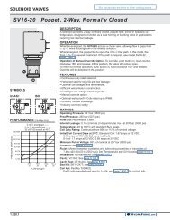
Normally Closed (SPxx-20x) ...........................00.02.10<br />
Schematic, Application Tips, Description,<br />
Operation, Features, Ratings, Performance<br />
Charts, Ordering Information<br />
Normally Open (SPxx-21x)..............................00.02.14<br />
Schematic, Application Tips, Description,<br />
Operation, Features, Ratings, Performance<br />
Charts, Ordering Information<br />
DIRECTIONAL CONTROL CIRCUITS,<br />
PRESSURE-COMPENSATED<br />
Direct-Acting<br />
Directional Control Valves - Getting Started ..00.02.30<br />
Theory of Operation, Schematic ....................00.02.31<br />
CYLINDER CIRCUITS, Direct-Acting<br />
Meter-In/Out (SPxx-47C) ..............................00.02.40<br />
Schematic, Application Tips, Description,<br />
Operation, Features, Ratings, Performance<br />
Charts, Ordering Information<br />
MOTOR CIRCUITS, Direct-Acting<br />
Meter-In/Out, Non-Restricted (SPxx-47D) ..00.02.50<br />
Schematic, Application Tips, Description,<br />
Operation, Features, Ratings, Performance<br />
Charts, Ordering Information<br />
Pilot-Operated<br />
Getting Started - Load Sense Basics .............00.04.01<br />
Theory of Operation, Schematic ....................00.04.02<br />
CYLINDER CIRCUITS, Pilot-Operated<br />
Meter-In/Out (PExx-S67C) ............................00.04.10<br />
Schematic, Application Tips, Description,<br />
Operation, Features, Ratings, Performance Charts,<br />
Ordering Information<br />
MOTOR CIRCUITS, Pilot-Operated<br />
Meter-In/Out, Non-Restricted (PExx-S67D) ...00.04.12<br />
Schematic, Application Tips, Description,<br />
Operation, Features, Ratings, Performance Charts,<br />
Ordering Information<br />
Meter-In/Out, Restricted (PExx-S67H) ...........00.04.14<br />
Schematic, Application Tips, Description,<br />
Operation, Features, Ratings, Performance Charts,<br />
Ordering Information<br />
Meter-In, Non-Restricted (PExx-S67K) ..........00.04.16<br />
Schematic, Application Tips, Description,<br />
Operation, Features, Ratings, Performance Charts,<br />
Ordering Information<br />
DETAILED SPECIFICATIONS<br />
Solenoid Operated On-Off Valves ..........................Section 1<br />
Electro-Proportional Valves ...................................Section 2<br />
SP08-20 .....................................................................2.008.1<br />
SP08-20A ..................................................................2.009.1<br />
SP10-20 .....................................................................2.010.1<br />
SP10-20A ..................................................................2.010.1<br />
SP12-20 .....................................................................2.012.1<br />
SP12-20A ..................................................................2.012.2<br />
SP08-21 .....................................................................2.020.1<br />
SP08-21A ..................................................................2.020.1<br />
SP10-21 .....................................................................2.021.1<br />
SP10-21A ..................................................................2.021.1<br />
SP12-21 .....................................................................2.022.1<br />
SP12-21A ..................................................................2.022.1<br />
SP08-47C ..................................................................2.110.1<br />
SP10-47C ..................................................................2.112.1<br />
SP08-47D ..................................................................2.120.1<br />
SP10-47D ..................................................................2.122.1<br />
Directional Valves....................................................Section 4<br />
HCV06-20 ..................................................................4.008.1<br />
HCV08-20 ..................................................................4.010.3<br />
HLS06-30...................................................................4.266.1<br />
HLS06-B30 ................................................................4.267.1<br />
PE12-S67C ................................................................4.416.1<br />
PE12-S67D ................................................................4.424.1<br />
PE12-S67H ................................................................4.428.1<br />
PE12-S67K ................................................................4.436.1<br />
Flow Control Valves ................................................Section 5<br />
EC08-32 .....................................................................5.418.1<br />
Pressure Control Valves .........................................Section 6<br />
RV08-20 .....................................................................6.010.1<br />
Warranty ...................................................................Section 9<br />
FIVE-YEAR LIMITED WARRANTY<br />
All <strong>HydraForce</strong> products carry a five-year limited warranty against defects in material and workmanship.<br />
For full warranty information see page the last page of this catalog.<br />
®<br />
00.00.02 HYDRAFORCE.com
A Word About Safety<br />
WARNING<br />
READ THIS DOCUMENT BEFORE INSTALLING OR USING HYDRAFORCE PRODUCTS.<br />
IMPROPER SELECTION, IMPROPER USE, USE BY ANYONE OTHER THAN TRAINED<br />
USERS HAVING APPROPRIATE TECHNICAL AND MECHANICAL EXPERTISE, OR<br />
FAILURE OF HYDRAFORCE PRODUCTS OR RELATED ITEMS RESULTING T<strong>HERE</strong>FROM<br />
CAN CAUSE DAMAGE TO EQUIPMENT OR PROPERTY, SERIOUS PERSONAL INJURY,<br />
OR DEATH.<br />
This document and other information from <strong>HydraForce</strong>, its subsidiaries and authorized distributors (collectively<br />
“<strong>HydraForce</strong>”) together only provide product installation guidelines and product or system usage options, each of<br />
which are intended to operate in conjunction with further investigation by trained users having appropriate technical<br />
and mechanical expertise to facilitate the safe handling and use of <strong>HydraForce</strong> products. <strong>HydraForce</strong> products are<br />
not intended to be used or handled by anyone other than trained users having appropriate technical and mechanical<br />
expertise. The information and documentation contained in our catalog and on the website, www.hydraforce.com, is<br />
provided for technical illustration purposes only and may not be used or relied upon as a statement of suitability for<br />
use in any particular application. Users, through their own analysis and testing, are solely responsible for making the<br />
final selection of <strong>HydraForce</strong> systems and components and for assuring that <strong>HydraForce</strong> products are used in a safe<br />
and intended manner with all performance, endurance, maintenance, safety and warning requirements necessary<br />
for safe application being met. Users are responsible for determining that <strong>HydraForce</strong> product data and specifications<br />
are suitable and sufficient for all intended applications and reasonably foreseeable uses of the components or<br />
systems. Each application is unique and prospective purchasers are responsible for conducting their own tests and<br />
studies to determine the fitness of <strong>HydraForce</strong>'s products for their particular purposes and specific applications.<br />
Since the use of the information contained in <strong>HydraForce</strong> product documentation, including this document, and the<br />
conditions under which <strong>HydraForce</strong> products are used are beyond the control of <strong>HydraForce</strong>, it is the obligation of<br />
each user of <strong>HydraForce</strong> products to carefully read and understand this document and all other documentation,<br />
instructions, and manuals supplied with <strong>HydraForce</strong> products and to determine the correct and safe methods of<br />
installation, inspection, testing, operation, and maintenance of <strong>HydraForce</strong> products, and the correct and safe conditions<br />
of use of <strong>HydraForce</strong> products and any systems into which they may be integrated by the user. In addition to<br />
the disclaimers and limitations of liability set forth below, in no event may <strong>HydraForce</strong> be held responsible for unsafe<br />
installation, inspection, testing, operation, and maintenance practices of users employing <strong>HydraForce</strong> products or for<br />
any property damage or personal injuries arising out of the use or handling of <strong>HydraForce</strong> products by anyone other<br />
than trained users having appropriate technical and mechanical expertise.<br />
DISCLAIMER OF WARRANTIES. USERS’ USE OF HYDRAFORCE PRODUCTS IS AT THEIR SOLE RISK, EXCEPT FOR ANY EXPRESS<br />
LIMITED WARRANTY THAT MAY BE PROVIDED FOR SPECIFIC HYDRAFORCE PRODUCTS. HYDRAFORCE EXPRESSLY DISCLAIMS,<br />
TO THE MAXIMUM EXTENT PERMITTED BY APPLICABLE LAW, ALL WARRANTIES OR ANY KIND, WHETHER EXPRESS OR IMPLIED,<br />
INCLUDING BUT NOT LIMITED TO THE IMPLIED WARRANTIES OF MERCHANTABILITY, FITNESS FOR A PARTICULAR PURPOSE, OR<br />
ARISING BY STATUTE OR OTHERWISE IN LAW OR FROM A COURSE OF DEALING OR USAGE OF TRADE. NO ADVICE OR INFORMA-<br />
TION, WHETHER ORAL OR WRITTEN, OBTAINED BY YOU FROM HYDRAFORCE OR CONTAINED IN THIS DOCUMENT OR ANY OF THE<br />
HYDRAFORCE PRODUCT DOCUMENTATION, SHALL CREATE ANY WARRANTY.<br />
LIMITATION OF LIABILITY. [OTHER THAN REMEDIES THAT ARE GRANTED UNDER ANY EXPRESS LIMITED WARRANTY THAT MAY<br />
BE PROVIDED FOR SPECIFIC HYDRAFORCE PRODUCTS,] HYDRAFORCE SHALL NOT BE LIABLE FOR, NOR SHALL YOU MAKE ANY<br />
CLAIM FOR (WHETHER BASED ON CONTRACT, TORT, PRODUCTS LIABILITY, STRICT OR STATUTORY LIABILITY, NEGLIGENCE OR<br />
OTHERWISE), ANY DIRECT, INDIRECT, INCIDENTAL, SPECIAL, CONSEQUENTIAL, PUNITIVE, OR EXEMPLARY DAMAGES (EVEN IF<br />
HYDRAFORCE HAS BEEN ADVISED OF THE POSSIBILITY OF SUCH DAMAGES) ARISING OUT OF USE OF HYDRAFORCE PRODUCTS,<br />
INCLUDING, BUT NOT LIMITED TO, DAMAGES FOR ECONOMIC LOSS OF PROFITS OR SAVINGS; LOST WAGES; DAMAGES TO OR<br />
LOSS OF USE OF PROPERTY; BODILY INJURY; MEDICAL PAYMENTS; PAIN AND SUFFERING; AND LOSS OF CONSORTIUM. IN THE<br />
EVENT THAT APPLICABLE LAW DOES NOT ALLOW THE EXCLUSION OF WARRANTIES STATED <strong>HERE</strong>IN OR THE LIMITATION OF<br />
LIABILITY STATED <strong>HERE</strong>IN, THEN YOU EXPRESSLY AGREE THAT IN NO EVENT WILL THE LIABILITY OF HYDRAFORCE, FOR ANY<br />
CLAIM OR DAMAGES <strong>HERE</strong>UNDER EXCEED THE PURCHASE PRICE PAID FOR THE HYDRAFORCE PRODUCT IN CONTROVERSY.<br />
<strong>HydraForce</strong> and the <strong>HydraForce</strong> logo are registered trademarks of <strong>HydraForce</strong>, Inc.<br />
The entire content of this catalog is copyright 2013 <strong>HydraForce</strong>, Inc.<br />
®<br />
HYDRAFORCE.com<br />
00.00.03
How to Use This <strong>Catalog</strong><br />
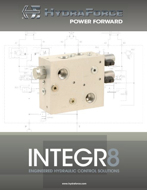
is a new concept in hydraulic controls<br />
Integr8 from <strong>HydraForce</strong>. It takes the best<br />
combination of cartridge valves and integrates them<br />
into optimally designed manifolds for cylinder and motor<br />
control. <strong>INTEGR8</strong> is the fastest way to arrive at efficient,<br />
reliable hydraulic control solutions.<br />
Here's how to <strong>INTEGR8</strong> your application:<br />
1. Start with the function you need - flow control or<br />
directional control, direct-acting or pilot-operated.<br />
2. Choose the <strong>INTEGR8</strong> component for the function,<br />
using the Table of Contents in this catalog. If you are<br />
using i-Design to build your circuit, select the <strong>INTEGR8</strong><br />
component from the library menu, or visit hydraforce.<br />
com/<strong>INTEGR8</strong> to download the base schematic.<br />
3. Choose your flow rate - each <strong>INTEGR8</strong> solution<br />
is available in several flow rates and can be adjusted<br />
within a range for the application. Refer to the<br />
RATINGS section for parameters.<br />
4. Fine-tune your circuit by adjusting or adding<br />
cartridge valves, specifying seals, etc.<br />
Specifying an <strong>INTEGR8</strong> control solution gives you<br />
flexibility to choose the flow rate, pressure rating, and<br />
control parameters you need for an application.<br />
Detailed specifications for the individual cartridge valves<br />
are provided in the <strong>HydraForce</strong> Master <strong>Catalog</strong>. You<br />
can always find the most current valve specifications and<br />
ratings online at www.hydraforce.com.<br />
<strong>To</strong> design your circuit, download free i-Design manifold<br />
design software at http://info.hydraforce.com/<br />
downloadi-Design<br />
Manifold design assistance is also available by contacting<br />
<strong>HydraForce</strong> at http://info.hydraforce.com/Free-<br />
Custom-Circuit-Consultation/. A <strong>HydraForce</strong> distributor<br />
or sales representative will consult with you to provide<br />
application engineering assistance.<br />
You can also email us at one of the following addresses:<br />
From the U.S. - sales-us@hydraforce.com<br />
From U.K and Europe - sales-uk@hydraforce.com<br />
From Asia, Africa, Australia, Pacific - sales-intl@hydraforce.com<br />
®<br />
00.00.04 HYDRAFORCE.com
<strong>INTEGR8</strong> - Engineered Hydraulic Control Solutions<br />
Here are 8 reasons to <strong>INTEGR8</strong>:<br />
Innovation - Expand your creative options with<br />
1 the largest range of performance-optimized cartridge<br />
valves in the industry. Cartridge valve and manifold<br />
system technologies provide performance options and<br />
feature flexibility unsurpassed by alternative valve<br />
configurations.<br />
System Efficiency - Cartridge valves can be<br />
2 combined and uniquely packaged to optimize machine<br />
efficiency, improve operator control, and<br />
integrate multiple functions into a common control<br />
scheme. Different-sized components can be inter-mixed<br />
to optimize metering characteristics, and minimize both<br />
size and cost. No need to oversize and compromise low<br />
flow functions in order to accommodate the highest flow<br />
function of the valve body. Each function is<br />
individually tailored.<br />
Serviceability - Significantly reduce machine<br />
3 downtime and cost for repair or maintenance with a<br />
screw-in manifold valve solution that is easily, quickly<br />
and economically serviced.<br />
Custom Capabilities - No fixed configuration<br />
4 castings. Manifold housings can be configured in a<br />
variety of sizes, shapes and materials to fit tight spaces.<br />
Port locations can be placed to improve hose routings,<br />
reduce installation time and minimize installed costs.<br />
Flexibility - <strong>INTEGR8</strong> components can be<br />
5 specified as tested, rated and performance detailed<br />
circuit configurations. Using these base configurations,<br />
systems can be customized with individual function<br />
control features, all within a machine specific, customer<br />
specified housing construction. Machine options can<br />
also be integrated allowing operating efficiency and<br />
vehicle performance to be maximized.<br />
Durability - Proven quality and reliability in the<br />
6 most demanding applications. Every manifold is<br />
100% function-tested at the factory, and every valve<br />
comes with the <strong>HydraForce</strong> five-year warranty.<br />
Optimal Performance - Cartridge valves<br />
7 offer precise, application-coordinated performance<br />
and unmatched tune-ability. Performance can be<br />
designed to offer features such as flow-sharing compensation,<br />
pre-compensation, port pressure protection,<br />
etc. Load sensing and/or pump unloading systems are<br />
also available to accommodate either fixed or variable<br />
pump supply.<br />
Fewer Leak Points - A single manifold block<br />
8 with fewer connections presents less opportunity for<br />
hydraulic leakage.<br />
=<br />
®<br />
HYDRAFORCE.com<br />
00.00.05
Flow Control Circuits, Pressure Compensated, Direct-Acting<br />
For detail,<br />
see Figure A<br />
Direct-acting, flow control valves can be used for load-holding, motor control and pressure limiting circuits.<br />
Direct-acting flow control circuits can be configured in<br />
a variety of ways to accomplish a full range of loadholding<br />
and motion control functions for hydraulically<br />
powered equipment. The hydraulic schematic above<br />
depicts several of the many possible ways you can build<br />
a circuit.<br />
<strong>To</strong> ensure a high-level of efficiency and consistent flow<br />
control, a load-sense based circuit featuring the SPxx-<br />
20x cartridge valve provides pressure-compensated<br />
proportional flow control. In addition to the SPxx-20x<br />
flow control valve, this direct-acting flow control circuit<br />
includes a HCVxx-20 check valve and ECxx-32 pressure<br />
compensator.<br />
CARTRIDGE VALVE and PORTING KEY<br />
1 SPxx-20 WP Work Port<br />
2 ECxx-32 P Inlet Port<br />
3 HCVxx-20 LS Load Sense Port<br />
2<br />
P<br />
WP<br />
1<br />
"A load-sense circuit featuring the<br />
SPxx-2x cartridge valve provides<br />
pressure-compensated<br />
proportional flow control.”<br />
Direct-acting flow control circuits are available in the following<br />
nominally rated flow capacities (with<br />
compensation - see details in following pages)<br />
• 10.6 to 22.7 lpm (2.8 to 6.0 gpm)<br />
• 37.1 to 70.1 lpm (9.8 to 18.5 gpm)<br />
• 55.0 to 106.0 lpm (14.5 to 28.0 gpm)<br />
LS<br />
FIGURE A - DIRECT-ACTING FLOW CONTROL<br />
3<br />
00.02.01<br />
®<br />
HYDRAFORCE.com
Theory of Operation - Direct-Acting Flow Control<br />
For simplicity, the load hold valve downstream of the<br />
work port (WP) has been omitted. In Figure A - DIRECT-<br />
ACTING FLOW CONTROL, all products are shown at<br />
rest and with no pressure applied to the inlet.<br />
In Figure B - DE-ENERGIZED, the pump is on and system<br />
pressure is fed to the inlet of the flow control valve.<br />
The compensator closes to block the flow of oil to the SP<br />
flow control.<br />
When the solenoid coil is energized (Figure C -<br />
ENERGIZED), oil is allowed to flow to the work port.<br />
The control pressure drop sensed across the flow control<br />
valve (SPxx-20x) will have increased to match the spring<br />
setting of the compensator (ECxx-32). The compensator<br />
spool opens and closes, balancing the supply pressure<br />
from the pump against the spring force plus load pressure<br />
to maintain consistent flow output. The compensator<br />
remains in this position as long as flow is commanded<br />
by the flow control valve. As command current to the coil<br />
is increased, this circuit not only provides precise metering<br />
and repeatable flow output, but flow output will be<br />
unaffected by changes in work port pressure.<br />
The load pressure sensed by the compensator is also<br />
communicated across the check valve (HCVxx-20), and<br />
out the LS port to feed the rest of the main load sense<br />
circuit. The HCVxx-20 is a spring-biased check valve,<br />
and only allows load pressure to feed into the main load<br />
sense circuit; pressure from main load sense circuit is<br />
blocked. The main load sense circuit may be controlled<br />
using a by-pass compensator and fixed displacement<br />
pump, or feed directly into a variable displacement type<br />
pump.<br />
Schematic showing flow control<br />
LS<br />
3<br />
1<br />
WP<br />
CARTRIDGE VALVE and PORTING KEY<br />
1 SPxx-20x WP Work Port<br />
2 ECxx-32 LS Load Sense Port<br />
3 HCV06-20 P Inlet Port<br />
At the heart of this flow control circuit, the SPxx-2x valve<br />
is a two-way, poppet-type valve available in two configurations:<br />
normally closed (SPxx-20) and normally open<br />
(SPxx-21). SPxx-2x flow control valves are available in<br />
two metering configurations: Standard (Fine) Metering<br />
and Linear Metering models. Fine Metering models will<br />
have slightly lower maximum flow output due to lower<br />
area gain of poppet. See Performance Charts for metering<br />
characteristics.<br />
P<br />
2<br />
1<br />
1<br />
2<br />
2<br />
P<br />
WP<br />
P<br />
WP<br />
LS<br />
3<br />
LS<br />
3<br />
FIGURE B - DE-ENERGIZED<br />
FIGURE C - ENERGIZED<br />
®<br />
HYDRAFORCE.com<br />
00.02.02
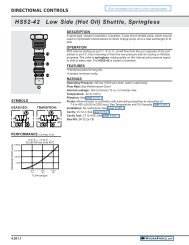
Direct-Acting, Pressure Compensated, Normally Closed<br />
3<br />
APPLICATION TIPS<br />
Typical applications include conveyor<br />
drives, positioning of horizontal<br />
actuators such as swing or side shift,<br />
and control of lifting functions, i.e.<br />
boom, bucket, fork, etc. The following<br />
application tips should be taken into<br />
consideration:<br />
• Use a closed loop current<br />
controller to ensure that constant<br />
current is delivered to the coil<br />
regardless of changes in resistance<br />
from temperature or voltage<br />
fluctuation. Refer to the Coil<br />
Operating Parameters chart on<br />
page 2.002.1 in the <strong>HydraForce</strong><br />
Technical <strong>Catalog</strong>.<br />
• Because SP valves have a variable<br />
orifice they are best applied<br />
when paired with a compensator<br />
to ensure consistent operation<br />
independent of any load-induced<br />
pressure.<br />
RATINGS<br />
Operating<br />
Pressure<br />
bar/psi<br />
Flow<br />
Rating<br />
Spring<br />
Size<br />
lpm/gpm<br />
1<br />
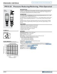
DESCRIPTION<br />
A combination of valves working together to provide optimal control of<br />
hydraulically powered functions. This direct-acting, pressure-compensated<br />
product controls flow proportionally in response to a change in current.<br />
Valves in circuit include:<br />
SPxx-20x flow control valve<br />
ECxx-32 pressure compensator<br />
HCVxx-20 check valve<br />
For applications requiring low work port leakage, the use of a pilot-operated<br />
check valve or counter balance valve is suggested.<br />
OPERATION<br />
When coil is de-energized, all ports are blocked. When coil is energized, flow<br />
is allowed to the work port (WP). The control pressure drop sensed across<br />
the flow control valve (SPxx-20x) will have increased to match the spring<br />
setting of the compensator (ECxx-32), and closes to restrict supply flow from<br />
pump. The compensator spool balances the supply pressure from the pump<br />
against the spring force plus load pressure to maintain consistent flow output.<br />
The compensator remains in this position as long as flow is commanded by<br />
the flow control valve.<br />
The load pressure sensed by the compensator is also communicated across<br />
the check valve (HCVxx-20), and out the LS port to feed the rest of the main<br />
load sense circuit. The main load sense circuit may be controlled using a<br />
by-pass compensator and fixed displacement pump, or feed directing into a<br />
variable displacement type pump.<br />
The heart of this flow control circuit is the SPxx-20x valve, a two-way, poppettype,<br />
normally closed valve. When de-energized, it acts as a check valve,<br />
blocking pump flow. When energized, the poppet lifts to allow pump flow out<br />
the active work port.<br />
HCVxx-20 is a spring-biased check valve, and only allows load pressure to<br />
feed into the main load sense circuit; pressure from main load sense circuit is<br />
blocked.<br />
FEATURES<br />
• Continuous duty unitized, molded coil or weathertight IP69-rated E-coil.<br />
• Several compensation values available.<br />
• Manual override and screen options.<br />
• Cartridge technology allows for ease of servicing.<br />
• Electronic controllers optimized for electro-hydraulic integration - visit<br />
http://www.hydraforce.com/EleVeCon/ElVeCon.htm<br />
• Industry common cavities<br />
SP08-20 SP08-20A SP10-20 SP10-20A SP12-20 SP12-20A<br />
207 bar/<br />
3000 psi<br />
WP<br />
LS<br />
P<br />
CARTRIDGE VALVE and<br />
PORTING KEY<br />
1 SPxx-20x WP Work Port<br />
2 ECxx-32 LS Load Sense Port<br />
3 HCV06-20 P Inlet Port<br />
2<br />
80 psi spring<br />
10.6 lpm/2.8 gpm<br />
150 psi spring<br />
14.8 lpm/3.9 gpm<br />
250 psi spring<br />
19.7 lpm/5.2 gpm<br />
207 bar/<br />
3000 psi<br />
80 psi spring<br />
11.7 lpm/3.1 gpm<br />
150 psi spring<br />
16.7 lpm/4.4 gpm<br />
250 psi spring<br />
23.1 lpm/6.1 gpm<br />
241 bar/<br />
3500 psi<br />
80 psi spring<br />
40.6 lpm/10.7 gpm<br />
160 psi spring<br />
55.7 lpm/14.7 gpm<br />
220 psi spring<br />
62.2 lpm/16.4 gpm<br />
241 bar/<br />
3500 psi<br />
80 psi spring<br />
44.7 lpm/11.8 gpm<br />
160 psi spring<br />
62.9 lpm/16.6 gpm<br />
220 psi spring<br />
70.1 lpm/18.5 gpm<br />
241 bar/<br />
3500 psi<br />
80 psi spring<br />
55.0 lpm/14.5 gpm<br />
160 psi spring<br />
72.4 lpm/19.1 gpm<br />
200 psi spring<br />
76.2 lpm/20.1 gpm<br />
241 bar/<br />
3500 psi<br />
80 psi spring<br />
57.2 lpm/15.1 gpm<br />
160 psi spring<br />
86.8 lpm/22.9 gpm<br />
200 psi spring<br />
86.4 lpm/22.8 gpm<br />
®<br />
00.02.10 HYDRAFORCE.com
Performance Charts - Standard Fine Metering SPxx-20<br />
SP08-20 Flow vs. Pressure<br />
Compensation with EC08-32 @ 1200 mA<br />
250 psi —— 150 psi 80 psi<br />
26.4/7.0<br />
SP08-20 Flow vs. Current<br />
with EC08-32 Compensator<br />
250 psi —— 150 psi 80 psi<br />
22.7/6.0<br />
20.6/300<br />
17.2/250<br />
SP08-20 Pressure Drop<br />
With Current at 100%<br />
FLOW lpm/gpm<br />
FLOW lpm/gpm<br />
22.7/6.0<br />
18.9/5.0<br />
15.1/4.0<br />
11.3/3.0<br />
7.5/2.0<br />
3.7/1.0<br />
0<br />
34.5 70.0 103.4 137.8 172.3 206.8<br />
500 1000 1500 2000 2500 3000<br />
DIFFERENTIAL PRESSURE bar/psi<br />
SP10-20 Flow vs. Pressure<br />
Compensation with EC12-32 @ 1200 mA<br />
220 psi —— 80 psi<br />
132.1/35.0<br />
113.5/30.0<br />
17.2/25.0<br />
75.7/20.0<br />
56.7/15.0<br />
37.8/10.0<br />
18.9/5.0<br />
0<br />
34.5 70.0 103.4 137.8 172.3 206.8<br />
500 1000 1500 2000 2500 3000<br />
DIFFERENTIAL PRESSURE bar/psi<br />
SP12-20 Flow vs. Pressure<br />
Compensation with EC12-32 @ 1200 mA<br />
200 psi —— 80 psi<br />
132.1/35.0<br />
FLOW lpm/gpm<br />
FLOW lpm/gpm<br />
18.9/5.0<br />
15.1/4.0<br />
11.3/3.0<br />
7.5/2.0<br />
3.7/1.0<br />
0<br />
66.2/17.5<br />
56.7/15.0<br />
47.3/12.5<br />
37.8/10.0<br />
28.3/7.5<br />
18.9/5.0<br />
75.7/20.0<br />
0<br />
200<br />
100<br />
400<br />
200<br />
600<br />
300<br />
800<br />
400<br />
1000<br />
500<br />
CURRENT mA (12V/24V)<br />
SP10-20 Flow vs. Current<br />
Compensation with EC12-32<br />
220 psi —— 80 psi<br />
200<br />
100<br />
400<br />
200<br />
600<br />
300<br />
800<br />
400<br />
1000<br />
500<br />
CURRENT mA (12V/24V)<br />
SP12-20 Flow vs. Current<br />
Compensation with EC16-32<br />
200 psi —— 80 psi<br />
1200<br />
600<br />
PRESSURE bar/psi<br />
PRESSURE bar/psi<br />
13.7/200<br />
10.3/150<br />
6.9/100<br />
3.4/50<br />
20.6/300<br />
17.2/250<br />
13.7/200<br />
10.3/150<br />
6.9/100<br />
3.4/50<br />
20.6/300<br />
0 15.1 30.2 45.4 60.5<br />
4 8 12 16 75.7 90.8<br />
20 24 105.9<br />
28 113.5<br />
30<br />
FLOW lpm/gpm<br />
SP10-20 Pressure Drop<br />
With Current at 100%<br />
0 15.1 30.2 45.4 60.5 75.7 90.8 105.9113.5<br />
4 8 12 16 20 24 28 30<br />
FLOW lpm/gpm<br />
SP12-20 Pressure Drop<br />
With Current at 100%<br />
FLOW lpm/gpm<br />
113.5/30.0<br />
17.2/25.0<br />
75.7/20.0<br />
56.7/15.0<br />
37.8/10.0<br />
FLOW lpm/gpm<br />
66.2/17.5<br />
56.7/15.0<br />
47.3/12.5<br />
37.8/10.0<br />
28.3/7.5<br />
PRESSURE bar/psi<br />
17.2/250<br />
13.7/200<br />
10.3/150<br />
6.9/100<br />
3.4/50<br />
18.9/5.0<br />
18.9/5.0<br />
0<br />
34.5<br />
500<br />
70.0<br />
1000<br />
103.4<br />
1500<br />
137.8<br />
2000 172.3<br />
2500<br />
206.8<br />
3000<br />
DIFFERENTIAL PRESSURE bar/psi<br />
0<br />
200<br />
100<br />
400<br />
200<br />
600<br />
300<br />
800<br />
400<br />
1000<br />
500<br />
CURRENT mA (12V/24V)<br />
1200<br />
600<br />
0 15.1 30.2 45.4 60.5 75.7 90.8 105.9113.5<br />
4 8 12 16 20 24 28 30<br />
FLOW lpm/gpm<br />
Notes:<br />
1. Flow charts for the SP10-xx and SP12-xx depict flow ratings with high and low spring selections. See Ratings table for flow<br />
rates with intermediate sized spring.<br />
2. Pressure drop performance is based upon cavity machining and associated port connections machined in accordance with<br />
<strong>HydraForce</strong> cavity specifications. Pressure drop performance is subject to change based on actual manifold/circuit design.<br />
®<br />
HYDRAFORCE.com<br />
00.02.11
Performance Charts - Linear Metering Option SPxx-20A<br />
FLOW lpm/gpm<br />
SP08-20A Flow vs. Pressure<br />
Compensation with EC08-32 @ 1200 mA<br />
250 psi —— 150 psi 80 psi<br />
26.4/7.0<br />
22.7/6.0<br />
18.9/5.0<br />
15.1/4.0<br />
11.3/3.0<br />
7.5/2.0<br />
FLOW lpm/gpm<br />
SP08-20A Flow vs. Current<br />
with EC08-32 Compensator<br />
250 psi —— 150 psi 80 psi<br />
22.7/6.0<br />
18.9/5.0<br />
15.1/4.0<br />
11.3/3.0<br />
7.5/2.0<br />
PRESSURE bar/psi<br />
45.5/650<br />
37.9/550<br />
31.0/450<br />
24.1/350<br />
17.2/250<br />
10.3/150<br />
SP08-20A Pressure Drop<br />
With Current at 100%<br />
3.7/1.0<br />
3.7/1.0<br />
3.4/50<br />
0<br />
34.5<br />
500<br />
70.0<br />
1000<br />
103.4<br />
1500<br />
137.8<br />
2000 172.3<br />
2500<br />
206.8<br />
3000<br />
DIFFERENTIAL PRESSURE bar/psi<br />
0<br />
200<br />
100<br />
400<br />
200<br />
600<br />
300<br />
800<br />
400<br />
CURRENT mA (12V/24V)<br />
1000<br />
500<br />
0<br />
15.1<br />
4<br />
30.2<br />
8<br />
45.4 60.5 75.7 90.8<br />
12 16 20 24<br />
FLOW lpm/gpm<br />
105.9113.5<br />
28 30<br />
FLOW lpm/gpm<br />
SP10-20A Flow vs. Pressure<br />
Compensation with EC12-32 @ 1200 mA<br />
220 psi —— 80 psi<br />
132.1/35.0<br />
113.5/30.0<br />
17.2/25.0<br />
75.7/20.0<br />
56.7/15.0<br />
37.8/10.0<br />
FLOW lpm/gpm<br />
66.2/17.5<br />
56.7/15.0<br />
47.3/12.5<br />
37.8/10.0<br />
28.3/7.5<br />
SP10-20A Flow vs. Current<br />
Compensation with EC12-32<br />
220 psi —— 80 psi<br />
PRESSURE bar/psi<br />
48.2/700<br />
41.3/600<br />
34.4/500<br />
27.5/400<br />
20.6/300<br />
13.7/200<br />
SP10-20A Pressure Drop<br />
With Current at 100%<br />
18.9/5.0<br />
18.9/5.0<br />
6.9/100<br />
0<br />
34.5<br />
500<br />
70.0<br />
1000<br />
103.4<br />
1500<br />
137.8<br />
2000 172.3<br />
2500<br />
206.8<br />
3000<br />
DIFFERENTIAL PRESSURE bar/psi<br />
0<br />
200<br />
100<br />
400<br />
200<br />
600<br />
300<br />
800<br />
400<br />
1000<br />
500<br />
CURRENT mA (12V/24V)<br />
1200<br />
600<br />
0<br />
15.1<br />
4<br />
30.2<br />
8<br />
45.4 60.5<br />
12 16 75.7 90.8<br />
20 24 105.9<br />
28 113.5<br />
30<br />
FLOW lpm/gpm<br />
SP12-20A Flow vs. Pressure<br />
Compensation with EC12-32 @ 1200 mA<br />
200 psi —— 80 psi<br />
132.1/35.0<br />
85.1/22.0<br />
SP12-20A Flow vs. Current<br />
with EC16-32 Compensator<br />
200 psi —— 80 psi<br />
48.2/700<br />
SP12-20A Pressure Drop<br />
With Current at 100%<br />
113.5/30.0<br />
75.7/20.0<br />
41.3/600<br />
FLOW lpm/gpm<br />
17.2/25.0<br />
75.7/20.0<br />
56.7/15.0<br />
37.8/10.0<br />
18.9/5.0<br />
FLOW lpm/gpm<br />
66.2/17.5<br />
56.7/15.0<br />
47.3/12.5<br />
37.8/10.0<br />
28.3/7.5<br />
PRESSURE bar/psi<br />
34.4/500<br />
27.5/400<br />
20.6/300<br />
13.7/200<br />
6.9/100<br />
0<br />
34.5 70.0 103.4 137.8 172.3 206.8<br />
500 1000 1500 2000 2500 3000<br />
DIFFERENTIAL PRESSURE bar/psi<br />
18.9/5.0<br />
0<br />
200<br />
100<br />
400<br />
200<br />
600<br />
300<br />
800<br />
400<br />
1000<br />
500<br />
CURRENT mA (12V/24V)<br />
1200<br />
600<br />
0<br />
15.1<br />
4<br />
30.2<br />
8<br />
45.4 60.5<br />
12 16 75.7 90.8<br />
20 24 105.9<br />
28 113.5<br />
30<br />
FLOW lpm/gpm<br />
Notes:<br />
1. Flow charts for the SP10-xx and SP12-xx depict flow ratings with high and low spring selections. See Ratings table for flow<br />
rates with intermediate sized spring.<br />
2. Pressure drop performance is based upon cavity machining and associated port connections machined in accordance with<br />
<strong>HydraForce</strong> cavity specifications. Pressure drop performance is subject to change based on actual manifold/circuit design.<br />
®<br />
00.02.12 HYDRAFORCE.com
Ordering Information - SPxx-20 and SPxx-20A<br />
Metering Options<br />
<strong>HydraForce</strong> offers a choice of two metering options on its SPxx-20 cartridge<br />
valves. The standard metering option provides fine metering for smooth<br />
control. For applications that require extra flow capacity rather than fine<br />
metering, a linear metering option is available.<br />
Flow vs. current performance for standard fine and linear metering is charted<br />
on the adjacent graph.<br />
<strong>To</strong> specify the Linear Metering Option, add an "A" to the valve model code.<br />
See the <strong>To</strong> Order section.<br />
FLOW lpm/gpm (Increasing)<br />
SPxx-20 Metering Characteristic<br />
SPxx-20A —— SPxx-20<br />
CURRENT mA (Increasing)<br />
TO ORDER<br />
<strong>To</strong> order, refer to ordering information for the individual cartridge valves.<br />
Flow Control Elements<br />
Flow Rating<br />
10.6 lpm (2.8 gpm)<br />
Control Option<br />
1 2 3<br />
Electro-Proportional<br />
Flow Control Valve Compensator Check Valve<br />
EC08-32-0-N-80<br />
14.8 lpm (3.9 gpm) SP08-20<br />
EC08-32-0-N-150<br />
19.7 lpm (5.2 gpm) EC08-32-0-N-250<br />
11.7 lpm (3.1 gpm)<br />
EC08-32-0-N-80<br />
16.7 lpm ( 4.4 gpm) SP08-20A<br />
EC08-32-0-N-150<br />
23.1 lpm (6.1 gpm) EC08-32-0-N-250<br />
40.6 lpm (10.7 gpm)<br />
EC12-32-0-N-80<br />
55.7 lpm (14.7 gpm) SP10-20<br />
EC12-32-0-N-160<br />
62.2 lpm (16.4 gpm) EC12-32-0-N-220<br />
44.7 lpm (11.8 gpm)<br />
EC12-32-0-N-80<br />
62.9 lpm (16.6 gpm) SP10-20A<br />
EC12-32-0-N-160<br />
70.1 lpm (18.5 gpm) EC12-32-0-N-220<br />
55.0 lpm (14.5 gpm)<br />
EC16-32-0-N-80<br />
72.4 lpm/19.1 gpm SP12-20<br />
EC12-32-0-N-160<br />
76.2 lpm (20.1 gpm) EC16-32-0-N-200<br />
57.2 lpm (15.1 gpm)<br />
EC16-32-0-N-80<br />
86.8 lpm/22.9 gpm SP12-20A<br />
EC12-32-0-N-160<br />
86.4.0 lpm (23.3 gpm) EC16-32-0-N-200<br />
HVC06-20-0-U-05<br />
®<br />
HYDRAFORCE.com<br />
00.02.13
Direct-Acting, Pressure Compensated, Normally Open<br />
LS<br />
3<br />
1<br />
WP<br />
CARTRIDGE VALVE and<br />
PORTING KEY<br />
1 SPxx-21x WP Work Port<br />
2 ECxx-32 LS Load Sense Port<br />
3 HCV06-20 P Inlet Port<br />
APPLICATION TIPS<br />
Typical applications include conveyor<br />
drives, positioning of horizontal<br />
actuators such as swing or side shift,<br />
and control of lifting functions, i.e.<br />
boom, bucket, fork, etc.<br />
The following application tips should<br />
be taken into consideration:<br />
• Use a closed loop current<br />
controller to ensure that constant<br />
current is delivered to the coil<br />
regardless of changes in resistance<br />
from temperature or voltage<br />
fluctuation. Refer to the Coil<br />
Operating Parameters chart on<br />
page 2.002.1 in the <strong>HydraForce</strong><br />
Technical <strong>Catalog</strong>.<br />
• Because SP valves have a variable<br />
orifice they are best applied<br />
when paired with a compensator<br />
to ensure consistent operation<br />
independent of any load-induced<br />
pressure.<br />
P<br />
2<br />
DESCRIPTION<br />
A combination of valves working together to provide optimal control of<br />
hydraulically powered functions. This direct-acting, pressure-compensated<br />
product controls flow proportionally in response to a change in current.<br />
Valves in circuit include:<br />
SPxx-21x flow control valve<br />
ECxx-32 pressure compensator<br />
HCVxx-20 check valve<br />
For applications requiring low work port leakage, the use of a pilot-operated<br />
check valve or counter balance valve is suggested.<br />
OPERATION<br />
When coil is de-energized, flow is allowed to the work port (WP). When<br />
energized, flow is blocked. The control pressure drop sensed across the flow<br />
control valve (SPxx-21x) will have increased to match the spring setting of<br />
the compensator (ECxx-32), and closes to restrict supply flow from pump.<br />
The compensator spool balances the supply pressure from the pump against<br />
the spring force plus load pressure to maintain consistent flow output. The<br />
compensator remains in this position as long as flow is commanded by flow<br />
control valve.<br />
The load pressure sensed by the compensator is also communicated across<br />
the check valve (HCVxx-20), and out the LS port to feed the rest of the main<br />
load sense circuit. The main load sense circuit may be controlled using a<br />
by-pass compensator and fixed displacement pump, or feed directing into a<br />
variable displacement type pump.<br />
The heart of this flow control circuit is the SPxx-21x valve, a two-way, poppettype,<br />
normally open valve. When de-energized,it allows flow from the work<br />
port. When energized, the poppet closes to block flow from the work port.<br />
HCVxx-20 is a spring-biased check valve, and only allows load pressure to<br />
feed into the main load sense circuit; pressure from main load sense circuit is<br />
blocked.<br />
FEATURES<br />
• Continuous duty unitized, molded coil or weathertight IP69-rated E-coil.<br />
• Several compensation values available.<br />
• Manual override and screen options.<br />
• Cartridge technology allows for ease of servicing.<br />
• Electronic controllers optimized for electro-hydraulic integration - visit<br />
http://www.hydraforce.com/EleVeCon/ElVeCon.htm<br />
• Industry common cavities<br />
RATINGS<br />
Operating Pressure<br />
bar/psi<br />
Flow Rating<br />
Spring Size<br />
lpm/gpm<br />
SP08-21 SP10-21 SP10-21A SP12-21 SP12-21A<br />
207 bar/<br />
3000 psi<br />
80 psi spring<br />
11.7 lpm/3.1 gpm<br />
150 psi spring<br />
17.0 lpm/4.5 gpm<br />
250 psi spring<br />
22.7 lpm/6.0 gpm<br />
241 bar/<br />
3500 psi<br />
80 psi spring<br />
37.1 lpm/9.8 gpm<br />
160 psi spring<br />
53.4 lpm/14.1 gpm<br />
220 psi spring<br />
60.3 lpm/15.9 gpm<br />
241 bar/<br />
3500 psi<br />
80 psi spring<br />
39.8 lpm/10.5 gpm<br />
160 psi spring<br />
58.4 lpm/15.4 gpm<br />
220 psi spring<br />
65.6 lpm/17.3 gpm<br />
241 bar/<br />
3500 psi<br />
80 psi spring<br />
62.9 lpm/16.6 gpm<br />
160 psi spring<br />
88.7 lpm/23.4 gpm<br />
200 psi spring<br />
98.5 lpm/26.0 gpm<br />
241 bar/<br />
3500 psi<br />
80 psi spring<br />
71.3 lpm/18.8 gpm<br />
160 psi spring<br />
95.5 lpm/28 gpm<br />
200 psi spring<br />
106.0 lpm28.0 gpm<br />
®<br />
00.02.14 HYDRAFORCE.com
Performance Charts - Standard Fine Metering SPxx-21<br />
SP08-21 Flow vs. Pressure<br />
Compensation with EC08-32 @ 0 mA<br />
250 psi —— 150 psi 80 psi<br />
26.4/7.0<br />
SP08-21 Flow vs. Current<br />
with EC08-32 Compensator<br />
250 psi —— 150 psi 80 psi<br />
26.4/7.0<br />
48.2/700<br />
SP08-21 Pressure Drop<br />
With Current at 0 mA<br />
22.7/6.0<br />
22.7/6.0<br />
41.3/600<br />
FLOW lpm/gpm<br />
18.9/5.0<br />
15.1/4.0<br />
11.3/3.0<br />
7.5/2.0<br />
3.7/1.0<br />
FLOW lpm/gpm<br />
18.9/5.0<br />
15.1/4.0<br />
11.3/3.0<br />
7.5/2.0<br />
3.7/1.0<br />
PRESSURE bar/psi<br />
34.4/500<br />
27.5/400<br />
20.6/300<br />
13.7/200<br />
6.9/100<br />
0<br />
34.5 70.0 103.4 137.8 172.3 206.8<br />
500 1000 1500 2000 2500 3000<br />
DIFFERENTIAL PRESSURE bar/psi<br />
0<br />
200<br />
100<br />
400<br />
200<br />
600<br />
300<br />
800<br />
400<br />
1000<br />
500<br />
CURRENT mA (12V/24V)<br />
1200<br />
600<br />
0<br />
15.1<br />
4<br />
30.2<br />
8<br />
45.4 60.5<br />
12 16 75.7 90.8<br />
20 24 105.9<br />
28 113.5<br />
30<br />
FLOW lpm/gpm<br />
FLOW lpm/gpm<br />
SP10-21 Flow vs. Pressure<br />
Compensation with EC12-32 @0 mA<br />
220 psi —— 80 psi<br />
66.2/17.5<br />
56.7/15.0<br />
47.3/12.5<br />
37.8/10.0<br />
28.3/7.5<br />
18.9/5.0<br />
FLOW lpm/gpm<br />
66.2./17.5<br />
56.7/15.0<br />
47.3/12.5<br />
37.8/10.0<br />
28.3/7.5<br />
18.9/5.0<br />
SP10-21 Flow vs. Current<br />
Compensation with EC12-32<br />
220 psi —— 80 psi<br />
PRESSURE bar/psi<br />
48.2/700<br />
41.3/600<br />
34.4/500<br />
27.5/400<br />
20.6/300<br />
13.7/200<br />
SP10-21 Pressure Drop<br />
With Current at 0 mA<br />
9.4/2.5<br />
9.4/2.5<br />
6.9/100<br />
0<br />
34.5<br />
500<br />
70.0<br />
1000<br />
103.4<br />
1500<br />
137.8<br />
2000<br />
172.3<br />
2500<br />
206.8<br />
3000<br />
DIFFERENTIAL PRESSURE bar/psi<br />
0<br />
200<br />
100<br />
400<br />
200<br />
600<br />
300<br />
800<br />
400<br />
CURRENT mA (12V/24V)<br />
1000<br />
500<br />
1200<br />
600<br />
0<br />
15.1<br />
4<br />
30.2<br />
8<br />
45.4 60.5<br />
12 16 75.7 90.8<br />
20 24 105.9<br />
28 113.5<br />
30<br />
FLOW lpm/gpm<br />
FLOW lpm/gpm<br />
SP12-21 Flow vs. Pressure<br />
Compensation with EC16-32 @0 mA<br />
200 psi —— 80 psi<br />
105.9/28<br />
90.8/24<br />
75.7/20<br />
60.5/16<br />
45.5/12<br />
30.2/8<br />
FLOW lpm/gpm<br />
105.9/28.0<br />
90.8/24.0<br />
75.7/20.0<br />
60.5/16.0<br />
45.5/12.0<br />
30.2/8.0<br />
SP12-21 Flow vs. Current<br />
Compensation with EC16-32<br />
200 psi —— 80 psi<br />
PRESSURE bar/psi<br />
48.2/700<br />
41.3/600<br />
34.4/500<br />
27.5/400<br />
20.6/300<br />
13.7/200<br />
SP12-21 Pressure Drop<br />
With Current at 0 mA<br />
15.1/4<br />
15.1/4.0<br />
6.9/100<br />
0<br />
34.5<br />
500<br />
70.0<br />
1000<br />
103.4<br />
1500<br />
137.8<br />
2000 172.3<br />
2500<br />
206.8<br />
3000<br />
DIFFERENTIAL PRESSURE bar/psi<br />
0<br />
200<br />
100<br />
400<br />
200<br />
600<br />
300<br />
800<br />
400<br />
1000<br />
500<br />
CURRENT mA (12V/24V)<br />
1200<br />
600<br />
0<br />
15.1<br />
4<br />
30.2<br />
8<br />
45.4 60.5<br />
12 16 75.7 90.8<br />
20 24 105.9<br />
28 113.5<br />
30<br />
FLOW lpm/gpm<br />
Notes:<br />
1. Flow charts for the SP10-xx and SP12-xx depict flow ratings with high and low spring selections. See Ratings table for flow<br />
rates with intermediate sized spring.<br />
2. Pressure drop performance is based upon cavity machining and associated port connections machined in accordance with<br />
<strong>HydraForce</strong> cavity specifications. Pressure drop performance is subject to change based on actual manifold/circuit design.<br />
®<br />
HYDRAFORCE.com<br />
00.02.15
Performance Charts - Linear Metering SPxx-21A<br />
FLOW lpm/gpm<br />
SP10-21A Flow vs. Pressure<br />
Compensation with EC12-32 @0 mA<br />
220 psi —— 80 psi<br />
105.9/28.0<br />
90.8/24.0<br />
75.7/20.0<br />
60.5/16.0<br />
52.9/12.0<br />
30.2/8.0<br />
15.1/4.0<br />
FLOW lpm/gpm<br />
66.2./17.5<br />
56.7/15.0<br />
47.3/12.5<br />
37.8/10.0<br />
28.3/7.5<br />
18.9/5.0<br />
9.4/2.5<br />
SP10-21A Flow vs. Current<br />
Compensation with EC12-32<br />
220 psi —— 80 psi<br />
PRESSURE bar/psi<br />
48.2/700<br />
41.3/600<br />
34.4/500<br />
27.5/400<br />
20.6/300<br />
13.7/200<br />
6.9/100<br />
SP10-21A Pressure Drop<br />
With Current at 0 mA<br />
0<br />
34.5<br />
500<br />
70.0<br />
1000<br />
103.4<br />
1500<br />
137.8<br />
2000 172.3<br />
2500<br />
206.8<br />
3000<br />
DIFFERENTIAL PRESSURE bar/psi<br />
0<br />
200<br />
100<br />
400<br />
200<br />
600<br />
300<br />
800<br />
400<br />
1000<br />
500<br />
CURRENT mA (12V/24V)<br />
1200<br />
600<br />
0<br />
15.1<br />
4<br />
30.2<br />
8<br />
45.4 60.5 75.7 90.8<br />
12 16 20 24<br />
FLOW lpm/gpm<br />
105.9113.5<br />
28 30<br />
FLOW lpm/gpm<br />
113.5/30.0<br />
SP12-21A Flow vs. Pressure<br />
Compensation with EC16-32 @0 mA<br />
200 psi —— 160 psi 80 psi<br />
94.6/25.0<br />
75.7/20.0<br />
56.7/15.0<br />
37.8/10.0<br />
FLOW lpm/gpm<br />
SP12-21A Flow vs. Current<br />
with EC16-32 Compensator<br />
200 psi —— 160 psi 80 psi<br />
104.0/27.5<br />
94.6/25.0<br />
85.1/22.5<br />
66.2/17.5<br />
47.3/12.5<br />
28.3/7.5<br />
PRESSURE bar/psi<br />
48.2/700<br />
41.3/600<br />
34.4/500<br />
27.5/400<br />
20.6/300<br />
13.7/200<br />
SP12-21A Pressure Drop<br />
With Current at 0 mA<br />
18.9/5.0<br />
18.8/5.0<br />
6.9/100<br />
0<br />
34.5<br />
500<br />
70.0<br />
1000<br />
103.4<br />
1500<br />
137.8<br />
2000<br />
172.3<br />
2500<br />
206.8<br />
3000<br />
DIFFERENTIAL PRESSURE bar/psi<br />
0<br />
200<br />
100<br />
400<br />
200<br />
600<br />
300<br />
800<br />
400<br />
1000<br />
500<br />
CURRENT mA (12V/24V)<br />
1200<br />
600<br />
0<br />
15.1<br />
4<br />
30.2<br />
8<br />
45.4 60.5 75.7 90.8<br />
12 16 20 24<br />
FLOW lpm/gpm<br />
105.9113.5<br />
28 30<br />
Notes:<br />
1. Flow charts for the SP10-xx and SP12-xx depict flow ratings with high and low spring selections. See Ratings table for flow<br />
rates with intermediate sized spring.<br />
2. Pressure drop performance is based upon cavity machining and associated port connections machined in accordance with<br />
<strong>HydraForce</strong> cavity specifications. Pressure drop performance is subject to change based on actual manifold/circuit design.<br />
®<br />
00.02.16 HYDRAFORCE.com
Ordering Information - SPxx-21<br />
Metering Options<br />
<strong>HydraForce</strong> offers a choice of two metering options on its SPxx-21 cartridge<br />
valves. The standard metering option provides fine metering for smooth<br />
control. For applications that require extra flow capacity rather than fine<br />
metering, a linear metering option is available.<br />
Flow vs. current performance for standard fine and linear metering is charted<br />
on the adjacent graph.<br />
<strong>To</strong> specify the Linear Metering Option, add an "A" to the valve model code.<br />
See the <strong>To</strong> Order section.<br />
SPxx-21 Metering Characteristic<br />
SPxx-21A —— SPxx-21<br />
FLOW lpm/gpm (Decreasing)<br />
CURRENT mA (Increasing)<br />
TO ORDER<br />
<strong>To</strong> order, refer to ordering information for the individual cartridge valves.<br />
Flow Control Elements<br />
Flow Rating<br />
11.7 lpm (3.1 gpm)<br />
1 2 3<br />
Electro-Proportional Flow<br />
Control Valve<br />
Compensator<br />
EC08-32-0-N-80<br />
17.1 lpm (4.5 gpm) SP08-21<br />
EC08-32-0-N-150<br />
22.7 lpm (6.0 gpm) EC08-32-0-N-250<br />
Check Valve<br />
37.1 lpm (9.8 gpm)<br />
EC12-32-0-N-80<br />
53.4 lpm/14.1 gpm SP10-21<br />
EC12-32-0-N-160<br />
60.3 lpm (15.9 gpm) EC12-32-0-N-220<br />
39.8 lpm (10.5 gpm)<br />
EC12-32-0-N-80<br />
58.4 lpm/15.4 gpm SP10-21A<br />
EC12-32-0-N-160<br />
65.6 lpm (17.3 gpm) EC12-32-0-N-220<br />
62.9 lpm (16.6 gpm)<br />
EC16-32-0-N-80<br />
88.7 lpm/23.4 gpm SP12-21<br />
EC16-32-0-N-160<br />
98.5 lpm (26.0 gpm) EC16-32-0-N-200<br />
71.3 lpm (18.8 gpm)<br />
EC16-32-0-N-80<br />
95.5 lpm/28 gpm SP12-21A<br />
EC16-32-0-N-160<br />
106.0 lpm (28.0 gpm) EC16-32-0-N-200<br />
HVC06-20-0-U-05<br />
®<br />
HYDRAFORCE.com<br />
00.02.17
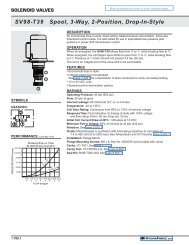
Directional Control Valves - Getting Started<br />
Direct-acting directional control valves can be used for several machine functions.<br />
It is well-understood that efficiency is paramount and<br />
machine developers are always seeking ways to make<br />
machines operate faster or move a greater load while<br />
decreasing the output of the prime mover.<br />
The backbone of a highly efficient hydraulic system is<br />
the load sense network. Load-sensing supports and<br />
sustains the delivery of pressurized hydraulic fluid<br />
throughout the system. It is interconnected with all of<br />
the other hydraulic components - the pumps, motors,<br />
accumulators and hydraulic valves. The load sense network<br />
depends on hydraulic control valves to regulate the<br />
demand of flow to each function. When developing your<br />
circuit, start with the basics of the load-sensing system.<br />
A Simple Load Sense System<br />
Shown in the illustration above is a load sense system<br />
with a simple, inexpensive gear pump and unique<br />
<strong>HydraForce</strong> components, such as the SPxx-47x electroproportional<br />
control valve.<br />
Initially, when a load sense system is activated and<br />
the operator has not selected a function, all flow from<br />
the pump is diverted to tank through the EPFR bypass<br />
compensator.<br />
This is advantageous from an efficiency standpoint,<br />
because the energy consumed is only that related to<br />
the flow from the pump and the bias spring value of the<br />
EPFR flow regulator.<br />
®<br />
00.02.30 HYDRAFORCE.com
Load-Sense System Basics<br />
For example, as current is applied to one of the coils of<br />
SP1, oil flows through EC1, SP1 and finally out through<br />
the work ports of either A1 or B1. As the actuator at A1<br />
moves it imposes a load on the hydraulic system. This<br />
load pressure is transmitted through the load sense port<br />
of SP1 and further passed on to the function compensator.<br />
Ultimately, the load pressure is conveyed across<br />
the load sense network across the load sense check<br />
valves (CV1 through CV3) to the main load sense line.<br />
Selecting Multiple Functions<br />
When multiple functions are operated simultaneously,<br />
only the highest load sense signal is allowed to pass to<br />
the main line through one of these check valves. As the<br />
operator demands a greater speed from the actuators<br />
(pressure doesn’t necessarily increase as function flow<br />
increases) and/or if the load pressure increases<br />
because of resistance, the load sense pressure increases.<br />
The EPFR1 opens or closes in response to a<br />
change in the load pressure.<br />
This changes the restriction in the pump to tank passage<br />
so that less or more flow is available in the hydraulic<br />
control circuit. Finally, the maximum pressure which the<br />
system can develop is regulated by the setting of the<br />
relief valve, RV1.<br />
actuators up until the point that the pressure equals that<br />
of the setting of RV1. Then flow will begin to exhaust<br />
across RV1. This system pressure is applied at the<br />
inlet of all three work functions. The individual function<br />
compensator valves (EC1, EC2 and EC3) will limit this<br />
pressure to each function to ensure consistent differential<br />
pressure across each SP valve. Thus, the speed at<br />
each actuator is controlled based on the opening of the<br />
orifice of the spool at the given work function and is not<br />
a function of the inlet pressure.<br />
Cartridge Valves Are The Building Blocks<br />
Apart from the clear efficiency advantages of a properly<br />
designed load sense system, a <strong>HydraForce</strong> circuit will<br />
take full advantage of customizing for each individual<br />
application. Cartridge valves, which are the building<br />
blocks of the hydraulic world, can be arranged and<br />
installed into a custom manifold, eliminating the necessity<br />
to connect individual valves externally. Further, the<br />
correct size cartridge relative to the flow demand can<br />
be selected for each actuator. Therefore, the cost and<br />
size of the valve assembly is decreased while improving<br />
performance.<br />
Three Functions in Operation<br />
One typical operating scenario could be that all three<br />
functions are running simultaneously. Assume that<br />
the resistance from the load between A2 and B2 is the<br />
greatest. The load pressure is transmitted through CV2.<br />
This pressure acts on EPFR1 and it closes in response<br />
to this pressure. The system pressure increases by<br />
the pressure required to move the load at port A2 or<br />
B2 plus the spring value of EPFR1. As the load pressure<br />
requirement increases eventually EPFR1 will close<br />
completely and all flow will be available to move the<br />
®<br />
HYDRAFORCE.com<br />
00.02.31
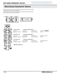
Theory of Operation - Direct-Acting Directional Control<br />
Shown below is a schematic of a typical directional<br />
control circuit, consisting of an SPxx-47C with an ECxx-<br />
32 and HLSxx-30 in combination to form the basis of<br />
a closed center, internally compensated load sensing<br />
directional control valve rated between 3 to 6 gpm<br />
(11 to 22 lpm) and 3500 psi (250 bar).<br />
"A typical directional control circuit<br />
featuring the SPxx-4x cartridge valve<br />
that provides a pressure-compensated,<br />
load-sensing directional control valve.”<br />
The HCV06-20 completes the circuit when it is in use<br />
with multiple parallel functions. The directional valve<br />
has two solenoids, S1 and S2. When the S1 coil is<br />
energized, flow is allowed to Work Port B. When S2 is<br />
energized, flow is allowed to Work Port A.<br />
In Figure A, the pump is off and no pressure is fed to<br />
the directional control.<br />
CARTRIDGE VALVE and PORTING KEY<br />
1 SPxx-47C A Work Port A<br />
2 ECxx-32 B Work Port B<br />
3 HLS06-30 LS Load Sense Port<br />
4 HCV06-20 P Inlet Port<br />
S1 Solenoid 1 T Tank<br />
S2 Solenoid 2<br />
1<br />
Note that unlike the schematic shown in the “Load<br />
Sense Basics” section, no load-holding valves are<br />
shown. These could be counterbalance valves or pilot<br />
operated check valves depending on the type of<br />
function being controlled as well as the neutral position<br />
of the directional control spool. Also, the relief valve and<br />
anti-cavitation protection check valves have been<br />
omitted. Only the essential valves of the circuit are<br />
identified.<br />
2<br />
S1<br />
S2<br />
3<br />
Schematic showing directional control<br />
for double-acting actuator control<br />
A<br />
A<br />
B<br />
6<br />
5<br />
5<br />
6<br />
P<br />
B<br />
4<br />
LS<br />
2<br />
S1<br />
1<br />
S2<br />
5A<br />
T<br />
4<br />
FIGURE A - Direct-acting, spool-type<br />
pressure-compensated directional control<br />
3<br />
LS<br />
P<br />
T<br />
Pressure Limiting Circuit<br />
00.02.32<br />
®<br />
HYDRAFORCE.com
Theory of Operation - Direct-Acting Directional Control<br />
In Figure B, the pump is on and system pressure is fed to<br />
the inlet of the directional control compensator. Since no<br />
current is applied to S1 and S2, the compensator closes<br />
and blocks the flow of oil to the SPxx-47C.<br />
Figure C depicts what occurs when the S1 coil is<br />
energized and the pump is on. The main spool of the<br />
directional control opens to allow oil to flow to Work Port B.<br />
At the same time oil is fed to the load sense network. The<br />
oil pushes the ball of the HLS06-30 load sense shuttle into<br />
a secondary position.<br />
The oil also biases the compensator into an open position.<br />
The pressure demand at the load plus the spring force acting<br />
on the compensator spool balances the inlet pressure.<br />
The compensator moves in response to a change in load<br />
or system pressure, thereby regulating the pressure drop<br />
across the main directional spool.<br />
As long as the hydraulic cylinder or motor demands flow,<br />
the compensator is in equilibrium. However, when the<br />
load or inlet pressure suddenly changes, the compensator<br />
responds accordingly. In other words, flow through the<br />
directional control is determined by the difference between<br />
load pressure induced at the actuator in the system and<br />
the main system pressure in combination with the restriction<br />
of the directional control valve (SPxx-47C working with<br />
the ECxx-32).<br />
As long as the actuator at Port A and B is moving (flow is<br />
required) the compensator will remain in an open equilibrium<br />
position. Oil also flows out of the load sense check<br />
valve that feeds the main load sense element. This main<br />
load sense element may be a valve that is external to the<br />
pump or it may be internal to the pump<br />
1 1<br />
S1<br />
S1<br />
2<br />
S2<br />
S2<br />
2<br />
3 3<br />
A<br />
A<br />
P<br />
B<br />
P<br />
B<br />
LS<br />
4<br />
T<br />
FIGURE B - Shown with pump on, coils de-energized<br />
and no flow post-compensated. The ECxx-32 pressure<br />
compensator regulates pressure of the hydraulic fluid.<br />
®<br />
HYDRAFORCE.com<br />
LS<br />
4<br />
T<br />
FIGURE C - Shown energized, when the S1 coil of<br />
the SPxx-47C is energized, it works together with<br />
the other three valves in a hydraulic manifold circuit.<br />
00.02.33
Direct-Acting Cylinder Circuits<br />
SCHEMATIC<br />
LS<br />
P<br />
T<br />
6<br />
3<br />
2<br />
5<br />
A<br />
S1<br />
4<br />
1<br />
B<br />
S2<br />
5<br />
6<br />
5A<br />
CARTRIDGE VALVE and PORTING KEY<br />
1 SPxx-47C 5a CR10-28 A Work Port A<br />
2 ECxx-32 6 CV08-20 B Work Port B<br />
3 HCV06-20 LS Load Sense Port<br />
4 HLS06-30 P Inlet Port<br />
5 RV08-20 T Tank<br />
APPLICATION TIPS<br />
• The SPxx-47C has all ports blocked when the spool is in<br />
neutral. During transition, the spool starts metering symmetrically<br />
in all directions, controllling flow to and from<br />
the load.<br />
• For cylinder applications it is recommended that the base<br />
end of the cylinder be connected to work port B.<br />
• SP Series valves are not to be used as the primary loadholding<br />
valve. If load-holding is required, then either a<br />
counterbalance valve or dual-pilot-operated check valve<br />
must be used.<br />
• When possible, the SPxx-47C valve should be mounted<br />
below the reservoir oil level. This will maintain oil in the<br />
armature preventing trapped air instability. If this is not<br />
feasible, mount the valve horizontally or install a check<br />
valve at the outlet of the manifold to prevent the introduction<br />
of air. See page 9.020.1 in the <strong>HydraForce</strong> Technical<br />
<strong>Catalog</strong>.<br />
• Use a closed loop current controller to ensure that constant<br />
current is delivered to the coil regardless of changes<br />
in resistance from temperature or voltage fluctuation.<br />
Refer to the Coil Operating Parameters chart on page<br />
2.002.1 in the <strong>HydraForce</strong> Technical <strong>Catalog</strong>.<br />
• Optimal control signal 100 Hz PWM at maximum dither level<br />
• Electronic controllers optimized for electro-hydraulic integration -<br />
visit http://www.hydraforce.com/EleVeCon/ElVeCon.htm<br />
00.02.40<br />
DESCRIPTION<br />
A combination of valves working together to control a<br />
double-acting cylinder. This direct-acting spool-type product<br />
controls flow proportionally in response to a change in<br />
current. The neutral position of the spool blocks oil at all<br />
ports. Valves in this circuit include: SPxx-47C, ECxx-32,<br />
HLS06-B30, RV08-20, HCV06-20, CV08-20 and an optional<br />
CR10-28. For applications requiring low work port leakage,<br />
the use of a pilot-operated check valve or counter<br />
balance valve is suggested.<br />
OPERATION<br />
When de-energized, work ports A and B are blocked. With<br />
power applied to either S1 or S2, flow is allowed to pass<br />
from P to either work port depending which coil is powered.<br />
The ECxx-32 assures constant pressure drop across the<br />
metering spool. This assures consistent work port flow<br />
regardless of inlet or load conditions. Features include:<br />
• Port reliefs to limit maximum work port pressure or protect<br />
the actuator against sudden shock load (RV08-20)<br />
• A single valve cross port relief can be used as an alternative<br />
to replace two individual work port relief valves<br />
between the work ports. (CR10-28)<br />
• Anti-cavitation check valves to ensure the cylinder<br />
remains filled with oil. (CV08-20)<br />
• Load sense checks valves can be used to allow multiple<br />
work sections to be connected in parallel (HCV06-20)<br />
FEATURES<br />
• Ideal for double-acting cylinder applications.<br />
• Continuous duty unitized, molded coil or weather tight<br />
IP69- rated E-coil<br />
• Hardened parts for long life.<br />
• Cartridges are voltage interchangeable and easy to<br />
service<br />
• Efficient wet-armature construction.<br />
• Choice of compensation values<br />
• Industry-common cavities<br />
RATINGS<br />
Operating Pressure<br />
bar/psi<br />
Flow Rating<br />
Spring Size<br />
lpm/gpm<br />
SP08-47C<br />
150 psi spring<br />
11.4 lpm/3.0 gpm<br />
SP10-47C<br />
241 bar/3500 psi<br />
80 psi spring<br />
15.5 lpm/4.1 gpm<br />
150 psi spring<br />
19.7 lpm/5.2 gpm<br />
250 psi spring<br />
21.6 lpm/5.7 gpm<br />
Hysteresis: Less than 7%<br />
Coil Duty Rating: Standard Coils and E-Coils: Continuous<br />
up to 115% of nominal voltage<br />
Oil Viscosity: 32 cSt/150 sus oil at 40C (104F)<br />
®<br />
HYDRAFORCE.com
Performance Charts - SPxx-47C<br />
PERFORMANCE<br />
FLOW (lpm/gpm)<br />
SP08-47C Flow vs. Pressure<br />
Compensation with EC08-32; 150 psi Spring<br />
37.8/10<br />
Coil S1<br />
Coil S2<br />
30.2/8<br />
22.1/6<br />
15.1/4<br />
7.5/2<br />
FLOW (lpm/gpm)<br />
37.8/10<br />
30.2/8<br />
22.1/6<br />
15.1/4<br />
7.5/2<br />
Coil S1<br />
SP10-47C Flow vs. Pressure<br />
Compensation with EC10-32<br />
250 psi<br />
150 psi<br />
80 psi<br />
Coil S2<br />
206.8<br />
3000<br />
137.5<br />
2000<br />
68.9<br />
1000<br />
0 68.9<br />
1000<br />
137.5<br />
2000<br />
DIFFERENTIAL PRESSURE bar/psi<br />
206.8<br />
3000<br />
206.8<br />
3000<br />
137.5<br />
2000<br />
68.9<br />
1000<br />
0 68.9<br />
1000<br />
137.5<br />
2000<br />
DIFFERENTIAL PRESSURE bar/psi<br />
206.8<br />
3000<br />
FLOW (lpm/gpm)<br />
SP08-47C Flow vs. Current<br />
Compensation with EC08-32; 150 psi Spring<br />
37.8/10<br />
Coil S1<br />
Coil S2<br />
30.2/8<br />
22.1/6<br />
15.1/4<br />
7.5/2<br />
FLOW (lpm/gpm)<br />
37.8/10<br />
30.2/8<br />
22.1/6<br />
15.1/4<br />
7.5/2<br />
SP10-47C Flow vs. Current<br />
Compensation with EC10-32<br />
Coil S1<br />
Coil S2<br />
250 psi<br />
150 psi<br />
80 psi<br />
1000<br />
500<br />
500<br />
250<br />
0 500<br />
250<br />
CURRENT mA (12V/24V)<br />
1000<br />
500<br />
1000<br />
500<br />
500<br />
250<br />
0 500<br />
250<br />
CURRENT mA (12V/24V)<br />
1000<br />
500<br />
PRESSURE (bar/psi)<br />
SP08-47C Pressure Drop<br />
Compensation with EC08-32; 150 psi Spring<br />
400/28<br />
Coil S1 Work Port B to Tank<br />
Coil S2<br />
Inlet to Work Port A<br />
300/21<br />
200/14<br />
100/7<br />
50/3<br />
PRESSURE (lbar/psi)<br />
400/28<br />
300/21<br />
200/14<br />
100/7<br />
50/3<br />
Coil S1<br />
SP10-47C Pressure Drop<br />
Compensation with EC10-32<br />
Work Port to Tank<br />
Inlet to Work Port<br />
Coil S2<br />
11.3<br />
3.0<br />
7.5<br />
2.0<br />
3.7<br />
1.0<br />
0 3.7<br />
1.0<br />
FLOW (lpm/gpm)<br />
7.5<br />
2.0<br />
11.3<br />
3.0<br />
22.1<br />
6.0<br />
15.4<br />
4.0<br />
0 7.5<br />
2.0<br />
FLOW (lpm/gpm)<br />
7.5<br />
2.0<br />
15.4<br />
4.0<br />
22.1<br />
6.0<br />
Note: Pressure drop performance is based upon cavity machining and associated port connections machined in accordance with <strong>HydraForce</strong> cavity<br />
specifications. Pressure drop performance is subject to change based on actual manifold/circuit design.<br />
TO ORDER<br />
<strong>To</strong> order, refer to ordering information for the individual cartridge valves.<br />
Directional Control Elements<br />
Control Options<br />
1 2 3 4 5 5a 6<br />
Flow Rating<br />
Directional<br />
Valve<br />
Compensator<br />
11.4 lpm (3.0 gpm) SP08-47C EC08-32-0-N-150<br />
Load Sense<br />
Check Valve<br />
Load Sense<br />
Valve<br />
Pressure<br />
Control<br />
Cross-over<br />
Relief<br />
Check Valve<br />
15.5 lpm (4.1 gpm)<br />
EC10-32-0-N-80<br />
19.7 lpm (5.2 gpm) SP10-47C EC10-32-0-N-150<br />
21.6 lpm (5.7 gpm) EC10-32-0-N-250<br />
HVC06-20-0-U-05 HLS06-B30-X RV08-20-0-N-XX CR10-28-0-N-XX CV08-20-0-N-05<br />
®<br />
HYDRAFORCE.com<br />
00.02.41
Direct-Acting Motor Circuits<br />
SCHEMATIC<br />
LS<br />
P<br />
T<br />
6<br />
3<br />
2<br />
5<br />
A<br />
S1<br />
4<br />
1<br />
B<br />
S2<br />
5<br />
6<br />
5A<br />
CARTRIDGE VALVE and PORTING KEY<br />
1 SPxx-47C 5a CR10-28 A Work Port A<br />
2 ECxx-32 6 CV08-20 B Work Port B<br />
3 HCV06-20 LS Load Sense Port<br />
4 HLS06-30 P Inlet Port<br />
5 RV08-20 T Tank<br />
APPLICATION TIPS<br />
• The SPxx-47D ports A and B are connected to tank<br />
when in neutral to prevent cavitation of a motor. During<br />
the transition, the symmetrical spool provides meter-in/<br />
meter-out flow control.<br />
• For stable performance it is recommended to either<br />
mount the valve assembly below reservoir level or<br />
mount a check valve at the outlet of the manifold to assure<br />
oil fills the armature tube of the directional valve.<br />
• SP Series valves are not to be used as the primary loadholding<br />
valve. If load-holding is required, use a counterbalance<br />
valve or dual-pilot-operated check valve.<br />
• Can be used where no load-holding is required, meter-in<br />
meter-out control is desired and unrestricted flow in the<br />
neutral position is desired. For example: If the application<br />
requires the actuator to free-wheel in the neutral<br />
position, the D spool should be used.<br />
• Use a closed loop current controller to ensure that<br />
constant current is delivered to the coil regardless of<br />
changes in resistance from temperature or voltage fluctuation.<br />
Refer to the Coil Operating Parameters chart on<br />
page 2.002.1 in the <strong>HydraForce</strong> Technical <strong>Catalog</strong>.<br />
• Optimal control signal 100 Hz PWM at maximum dither level<br />
• Electronic controllers optimized for electro-hydraulic integration<br />
- visit http://www.hydraforce.com/EleVeCon/ElVeCon.htm<br />
DESCRIPTION<br />
A combination of valves working together to control a bidirectional<br />
motor. This direct-acting spool-type product<br />
controls flow proportionally in response to a change in<br />
current. When the spool is in neutral position, the work ports<br />
are open to tank. Valves in this circuit include: SPxx-47D,<br />
ECxx-32, HLS06-B30, RV08-20, HCV06-20, CV08-20 and<br />
an optional CR10-28. For applications requiring low work<br />
port leakage, the use of a pilot-operated check valve or<br />
counter balance valve is suggested.<br />
OPERATION<br />
When de-energized ports A and B are connected to tank.<br />
With power applied to either S1 or S2, flow is allowed to<br />
pass from P to either work port depending which coil is powered.<br />
The ECxx-32 assures constant pressure drop across<br />
the metering spool. This assures consistent performance<br />
regardless of inlet or load conditions.<br />
Features include:<br />
• Port reliefs to limit maximum work port pressure or protect<br />
the actuator against sudden shock load (RV08-20)<br />
• A single valve cross port relief can be used as an alternative<br />
to replace two individual work port relief valves<br />
between the work ports. (CR10-28)<br />
• Anti-cavitation check valves to ensure the cylinder<br />
remains filled with oil. (CV08-20)<br />
• Load sense checks valves can be used to allow multiple<br />
work sections to be connected in parallel (HCV06-20)<br />
FEATURES<br />
• Ideal for motor applications.<br />
• Continuous duty unitized, molded coil or weather tight<br />
IP69 rated E-coil<br />
• Hardened parts for long life.<br />
• Cartridges are voltage interchangeable and easy to<br />
service<br />
• Efficient wet-armature construction.<br />
• Choice of compensation values<br />
• Industry-common cavities<br />
RATINGS<br />
Operating Pressure<br />
bar/psi<br />
Flow Rating<br />
Spring Size<br />
lpm/gpm<br />
SP08-47D<br />
150 psi spring<br />
11.0 lpm/2.9 gpm<br />
SP10-47D<br />
240 bar/3500 psi<br />
80 psi spring<br />
16.7 lpm/4.4 gpm<br />
150 psi spring<br />
20.5 lpm/5.4 gpm<br />
250 psi spring<br />
24.6 lpm/6.5 gpm<br />
Hysteresis: Less than 7%<br />
Coil Duty Rating: Standard Coils and E-Coils: Continuous<br />
up to 115% of nominal voltage<br />
Oil Viscosity: 32 cSt/150 sus oil at 40C (104F)<br />
®<br />
00.02.50 HYDRAFORCE.com
Performance Charts - SPxx-47D<br />
PERFORMANCE<br />
FLOW (lpm/gpm)<br />
SP08-47D Flow vs. Pressure<br />
Compensation with EC08-32; 150 psi Spring<br />
37.8/10<br />
30.2/8<br />
Coil S1<br />
Coil S2<br />
22.1/6<br />
15.1/4<br />
7.5/2<br />
FLOW (lpm/gpm)<br />
SP10-47D Flow vs. Pressure<br />
Compensation with EC10-32; 150 psi Spring<br />
37.8/10<br />
Coil S1 80 psi<br />
Coil S2<br />
150 psi<br />
30.2/8<br />
250 psi<br />
22.1/6<br />
15.1/4<br />
7.5/2<br />
FLOW (lpm/gpm)<br />
SP08-47D Flow vs. Current<br />
Compensation with EC08-32; 150 psi Spring<br />
37.8/10<br />
Coil S1<br />
Coil S2<br />
30.2/8<br />
22.1/6<br />
15.1/4<br />
7.5/2<br />
206.8<br />
3000<br />
138.8<br />
2000<br />
68.9<br />
1000<br />
0 68.9<br />
1000<br />
138.8<br />
2000<br />
DIFFERENTIAL PRESSURE bar/psi<br />
206.8<br />
3000<br />
FLOW (lpm/gpm)<br />
SP10-47D Flow vs. Current<br />
Compensation with EC10-32; 150 psi Spring<br />
37.8/10<br />
Coil S1<br />
Coil S2<br />
30.2/8<br />
22.1/6<br />
15.1/4<br />
7.5/2<br />
206.8<br />
3000<br />
138.8<br />
2000<br />
68.9<br />
1000<br />
0 68.9<br />
1000<br />
138.8<br />
2000<br />
DIFFERENTIAL PRESSURE bar/psi<br />
80 psi<br />
150 psi<br />
250 psi<br />
206.8<br />
3000<br />
1000<br />
500<br />
500<br />
0 500<br />
250<br />
250<br />
CURRENT mA (12V/24V)<br />
1000<br />
500<br />
1000<br />
500<br />
500<br />
250<br />
0 500<br />
250<br />
CURRENT mA (12V/24V)<br />
1000<br />
500<br />
PRESSURE (lpm/gpm)<br />
SP08-47D Pressure Drop<br />
Compensation with EC08-32; 150 psi Spring<br />
400/28<br />
Coil S1<br />
Coil S2<br />
300/21<br />
200/14<br />
100/7<br />
50/3<br />
Work Port B to Tank<br />
Inlet to Work Port A<br />
PRESSURE (lpm/gpm)<br />
SP10-47D Pressure Drop<br />
Compensation with EC10-32; 150 psi Spring<br />
400/28<br />
Coil S1<br />
Coil S2<br />
300/21<br />
200/14<br />
100/7<br />
50/3<br />
Work Port to Tank<br />
Inlet to Work Port<br />
11.3<br />
3.0<br />
7.5<br />
2.0<br />
3.7<br />
1.0<br />
0 3.7<br />
1.0<br />
FLOW (lpm/gpm)<br />
7.5<br />
2.0<br />
Directional<br />
Flow Rating Valve Compensator<br />
11.0 lpm (2.9 gpm) SP08-47D EC08-32-0-N-150<br />
11.3<br />
3.0<br />
Load Sense<br />
Check Valve<br />
Load Sense<br />
Valve<br />
22.1<br />
6.0<br />
15.4<br />
4.0<br />
Pressure<br />
Control<br />
7.5<br />
2.0<br />
0 7.5<br />
2.0<br />
FLOW (lpm/gpm)<br />
Note: Pressure drop performance is based upon cavity machining and associated port connections machined in<br />
accordance with <strong>HydraForce</strong> cavity specifications. Pressure drop performance is subject to change based on actual<br />
manifold/circuit design.<br />
TO ORDER<br />
<strong>To</strong> order, refer to ordering information for the individual cartridge valves.<br />
Directional Control Elements<br />
Control Options<br />
1 2 3 4 5 5a 6<br />
Cross-over<br />
Relief<br />
15.4<br />
4.0<br />
22.1<br />
6.0<br />
Check Valve<br />
16.7 lpm (4.4 gpm)<br />
20.5 lpm (5.4 gpm) SP10-47D EC10-32-0-N-150<br />
24.6 lpm (6.5 gpm) EC10-32-0-N-250<br />
®<br />
HYDRAFORCE.com<br />
EC10-32-0-N-80<br />
HVC06-20-0-U-05 HLS06-B30-X RV08-20-0-N-XX CR10-38x-0-N-XX CV08-20-0-N-05<br />
00.02.51
Pilot-Operated Directional Control Valves - Getting Started<br />
For detail,<br />
see Figure A<br />
Schematic showing pilot-operated load-holding circuits.<br />
Shown above is a load sense system with a an inexpensive<br />
gear pump and unique <strong>HydraForce</strong> components,<br />
including the PE16-S67 pilot-operated directional<br />
control valve, the EHPR electrohydraulic pressure reducing/relieving<br />
valve, and the EPFR logic element and flow<br />
regulator. Initially, when a load sense system is activated<br />
and the operator has not selected a function, all flow<br />
from the gear pump is diverted to tank through the EPFR<br />
bypass compensator. This is efficient, because the only<br />
energy consumed is related to the flow from the pump<br />
and the bias spring value of the EPFR flow regulator.<br />
When the operator selects a hydraulic function, its respective<br />
pressure-reducing/relieving valve (EHPR) valve<br />
is energized. For example, as current is applied to the<br />
EHPR1 coil, oil flows through EC1, PE1 and finally out<br />
through the work ports of either A1 or B1. As the actuator<br />
at A1 moves, it imposes a load on the hydraulic system.<br />
This load pressure is transmitted through the load<br />
shuttle LS1 and continues to the pressure compensator<br />
EC1. Load pressure is then conveyed across the load<br />
sense network via the load sense check valve (CV3) to<br />
the main load sense line.<br />
Selecting Multiple Functions<br />
When multiple functions are operated simultaneously,<br />
only the highest load sense signal is allowed to pass to<br />
the main line through one of these check valves. As the<br />
load changes, the EPFR1 opens or closes dynamically<br />
in response. This changes the restriction in the pump to<br />
tank passage so that less or more flow is available in the<br />
hydraulic control circuit. Finally, the maximum system<br />
pressure is regulated by the setting of the relief valve,<br />
RV1.<br />
Three Functions in Operation<br />
One typical operating scenario could be that all three<br />
functions are running simultaneously. Assume that the<br />
resistance from the load between A2 and B2 is the greatest.<br />
The load pressure is transmitted through LS2 and<br />
CV4. This pressure acts on EPFR1, which closes in response.<br />
The system pressure increases by the pressure<br />
required to move the load at port A2 or B2 plus the spring<br />
value of EPFR1. As the load pressure requirement<br />
increases eventually EPFR1 will close completely and all<br />
flow will be available to move the actuators up until the<br />
point that the pressure equals that of the setting of RV1.<br />
Then pilot pressure will be vented across the RV, allowing<br />
the EHPR1 to relieve the pressure to tank.<br />
This system pressure is applied at the inlet of all three<br />
work functions. The individual function compensator<br />
valves (EC1, EC2 and EC3) will limit this pressure to<br />
each function to ensure consistent differential pressure<br />
across each PE valve. Thus, the speed at each actuator<br />
is controlled based on the opening of the orifice of the<br />
spool at the given work function and is not a function of<br />
the load pressure.<br />
00.04.00<br />
®<br />
HYDRAFORCE.com
Pilot-Operated Solutions<br />
Pilot-operated directional control can be customized for the specific needs of an application with a choice of four valve<br />
spool configurations on the main PExx-4x four-way valve.<br />
For Cylinder<br />
Applications<br />
Meter In/Out<br />
This C spool configuration is ideal for cylinder applications requiring<br />
meter-in/meter-out control for a double-acting cylinder.<br />
For Motor<br />
Applications<br />
Meter In/Out<br />
For Restricted Motor<br />
Applications<br />
Meter In/Out<br />
For Motor<br />
Applications<br />
Meter In Only<br />
This D spool configuration is ideal for motor applications requiring<br />
meter-in/meter-out control for a hydraulic motor. It is a good choice<br />
for applications where no load-holding is required, and unrestricted<br />
flow in the neutral position is desired, for example, if the application<br />
requires the actuator to free-wheel in neutral.<br />
This H spool configuration is ideal for restricted motor applications<br />
requiring meter-in/meter-out control for a hydraulic motor, where<br />
efficient control of deceleration is desired, or where symmetrical<br />
meter-in/meter-out flow control is needed during shift. It can also be<br />
used for cylinder applications with bleed-down.<br />
This K spool configuration is ideal for motor applications requiring<br />
meter-in only control for a hydraulic motor. It is often used in conjunction<br />
with counterbalance valves. The meter-in only characteristic on<br />
this spool makes it an idea choice for control of overrunning or overcenter<br />
loads, since it ensures no back pressure is imposed on the<br />
counterbalance valves.<br />
®<br />
HYDRAFORCE.com<br />
00.04.01
Theory of Operation<br />
The directional control portion of this circuit<br />
consists of a PE16-S67C three-position<br />
four-way proportional valve with an EC16-32<br />
flow regulator/pressure compensator and<br />
two EHPR98-T35 reducing/relieving valves<br />
in combination to form the basis of a closed<br />
center, internally compensated load-sensing<br />
directional control circuit.<br />
Schematic showing PExx-67C valve<br />
used in a load-sensing application<br />
The PE directional valve is piloted by the<br />
EHPR valve. When S1 (EHPR1) is energized,<br />
flow passes through Work Port A and returns<br />
through Work Port B. When S2 (EHPR2) is<br />
energized, flow passes through Work Port B<br />
and returns through Work Port A.<br />
In Figure A, all valves are shown in the<br />
neutral (de-energized) position. The pump is<br />
not providing flow, so there is no pressure at<br />
the inlet.<br />
S1<br />
6<br />
S2<br />
"A PExx-S67C three-position,<br />
four-way proportional valve<br />
forms the basis of a closed center,<br />
pressure-compensated<br />
load-sensing directional control<br />
valve circuit."<br />
CARTRIDGE VALVE and PORTING KEY<br />
1 PExx-4xx A Work Port A<br />
2a EHPR98-T35 B Work Port B<br />
2b EHPR98-T35 LS Load Sense Port<br />
3 ECxx-32 P Inlet Port<br />
5 HLS06-30 T Tank Port<br />
6 HCV06-20 D Drain Tank<br />
S1 Solenoid 1 S2 Solenoid 2<br />
1<br />
2<br />
T<br />
S1<br />
A<br />
3<br />
B<br />
5<br />
4<br />
P<br />
S2<br />
LS<br />
D<br />
6<br />
FIGURE A - PILOT-OPERATED DIRECTIONAL CONTROL<br />
00.04.02<br />
®<br />
HYDRAFORCE.com
A<br />
A<br />
Pilot-Operated Solutions<br />
Figure B illustrates what occurs when S1 (EHPR1) and<br />
S2 (EHPR2) coils are both de-energized, and the pump<br />
is on while no other functions are active in the circuit.<br />
The main spool of the PE16-S67C directional valve<br />
blocks pump flow from entering Work Ports A and B.<br />
At the same time, it also blocks flow from exiting the<br />
Work Ports and going back to tank.<br />
With no flow, the load-induced pressure at the Work<br />
Ports acts on the EC16-32 pressure compensator,<br />
causing it to shift closed since there’s no opposing load<br />
sense pressure acting on the spring chamber side of the<br />
compensator.<br />
"Output from the PExx-S67C directional<br />
valve is determined by<br />
the valve's open area and<br />
applied differential pressure<br />
between main system pressure and<br />
load-induced pressure."<br />
Figure C depicts what occurs when S1 (EHPR1)<br />
receives an electronic input command. When<br />
commanded electro-proportionally, the S1 (EHPR1)<br />
provides a pilot pressure signal that shifts the PE16-<br />
S67C directional valve from a spring-centered neutral<br />
position to an open position. As the pilot pressure from<br />
the S1 (EHPR1) valve is increased, the PE16-S67C<br />
directional valve starts to meter pump flow out Work Port<br />
A to the hydraulic actuator. At the same time, return flow<br />
from the hydraulic actuator is metered from Work Port B<br />
through the PE16-S67C directional valve back to tank.<br />
As pump flow is fed to the hydraulic actuator, the loadinduced<br />
pressure is sensed by the LS1 shuttle valve,<br />
shifting the ball of the shuttle valve into a secondary position.<br />
The load sense output pressure from LS1 is communicated<br />
to the EC16-32 valve, shifting the compensator<br />
into a modulating position. The load-induced pressure<br />
demand plus the spring force acting on the compensator<br />
spool determines the inlet pressure seen by the pump.<br />
The compensator moves in response to changes in load<br />
and/or system pressure; thereby regulating the pressure<br />
drop across the main directional spool. As long as the<br />
hydraulic actuator demands flow, the pressure balance<br />
across the compensator is in equilibrium. However, when<br />
the load or inlet pressure suddenly changes, the compensator<br />
responds accordingly. In other words, flow through<br />
the PE16-S67C directional control is determined by the<br />
difference between load pressure induced at the actuator<br />
in the system and the main system pressure in combination<br />
with the restriction of the directional control valve.<br />
1<br />
2<br />
1<br />
2<br />
T<br />
S1<br />
T<br />
S1<br />
3<br />
5<br />
3<br />
5<br />
B<br />
4<br />
B<br />
4<br />
P<br />
S2<br />
P<br />
S2<br />
LS<br />
LS<br />
D<br />
D<br />
6<br />
6<br />
FIGURE B - Shown with pump on, coils de-energized<br />
and no flow post-compensated. The ECxx-32<br />
compensator regulates pressure of the hydraulic<br />
fluid.<br />
FIGURE C - Shown energized, when the coils of the<br />
PExx-S67C are energized, it works together with the<br />
other three valves in a hydraulic manifold circuit.<br />
®<br />
HYDRAFORCE.com<br />
00.04.03
Cylinder Circuits, Pilot-Operated, Meter In/Out<br />
A<br />
B<br />
DESCRIPTION<br />
6<br />
7<br />
7<br />
6<br />
A combination of valves working together to control a<br />
double-acting cylinder. This pilot-operated spool-type<br />
product controls flow proportionally in response to a<br />
change in current.<br />
LS<br />
P<br />
T<br />
D<br />
S1<br />
5a<br />
3<br />
2<br />
4<br />
APPLICATION TIPS<br />
When applying PE valves, as in the circuit above, the<br />
following application tips should be taken into<br />
consideration:<br />
• When using an EHPR valve, minimize back<br />
pressure at port D, as it may prevent the valve from<br />
fully shifting. Providing a separate drain line for the<br />
EHPR port D is required.<br />
• When using a pilot joystick, the minimum and<br />
maximum pilot pressures need to match the PE<br />
spool requirement to ensure full spool travel without<br />
excessive deadband (i.e. wasted joystick movement.)<br />
Maximum pilot pressure can be reduced to<br />
limit spool shift and thus limit flow through the PE<br />
valve as needed.<br />
• For applications requiring low work port leakage, the<br />
use of a pilot-operated check valve or counter balance<br />
valve is suggested.<br />
• Optimal control signal 100 Hz PWM at maximum<br />
dither level; recommended electronic controllers (see<br />
page 2.001.1 in the <strong>HydraForce</strong> Technical <strong>Catalog</strong><br />
or our Coretek Product Guide)<br />
1<br />
5b<br />
S2<br />
CARTRIDGE VALVE and PORTING KEY<br />
1 PExx-S67C A Work Port A<br />
2 ECxx-32 B Work Port B<br />
3 HCV06-20 LS Load Sense Port<br />
4 HLS06-30 P Inlet Port<br />
5a,b EHPR98-T35 T Tank<br />
6 RVxx-2x D Drain Tank<br />
7 CVxx-20 S1, S2 Solenoid 1, 2<br />
OPERATION<br />
When de-energized, no pilot pressure is applied to<br />
the PE valve. With power applied to either EHPR1 or<br />
EHPR2, flow is allowed to pass from P to either work<br />
port. The ECxx-32 ensures constant pressure drop<br />
across the metering spool to provide consistent<br />
performance regardless of inlet or load conditions. The<br />
valve spool is symmetrical, providing meter-in/meter-out<br />
control.<br />
Optional features include:<br />
• Port reliefs to limit maximum work port pressure or<br />
protect the actuator against sudden shock load.<br />
• Anti-cavitation check valves to ensure the cylinder<br />
remains filled with oil in case it is moved by an<br />
external force other than the hydraulic pump.<br />
• Load sense checks valves can be used to allow<br />
multiple work sections to be connected in parallel.<br />
• A cross port relief can be installed between the work<br />
ports to limit the torque or force that the actuator can<br />
apply<br />
FEATURES<br />
• Ideal for double-acting cylinder applications.<br />
• Continuous duty unitized, molded coil or weather<br />
tight IP69-rated E-coil<br />
• Hardened parts for long life.<br />
• Cartridges are voltage interchangeable and easy to<br />
service<br />
• Efficient wet-armature construction.<br />
• Choice of compensation values<br />
• Industry-common cavities<br />
RATINGS<br />
Operating Pressure<br />
bar/psi<br />
Flow Rating<br />
lpm/gpm<br />
PE12-S67C<br />
160 spring<br />
32.2 lpm/8.5 gpm<br />
220 spring<br />
36.0 lpm/9.5 gpm<br />
PE16-S67C<br />
240 bar/3500 psi<br />
80 spring<br />
49.3 lpm/13.0 gpm<br />
160 spring<br />
72.0 lpm/19 gpm<br />
200 spring<br />
83.4 lpm/22 gpm<br />
Hysteresis: Less than 7%<br />
Coil Duty Rating: Continuous up to 115% of nominal<br />
voltage<br />
Oil Viscosity: 32 cSt/150 sus oil at 40C (104F)<br />
®<br />
00.04.10 HYDRAFORCE.com
Performance Charts - PExx-S67C<br />
PERFORMANCE<br />
FLOW lpm/gpm<br />
52.9/14<br />
45.4/12<br />
37.8/10<br />
30.2/8<br />
22.7/6<br />
15.1/4<br />
7.5/2<br />
PE12-S67C<br />
FLOW vs. PILOT PRESSURE<br />
with EC12-32 Pressure Compensator options:<br />
15.2 bar/220 psi - - -; 11.0 bar/160 psi<br />
Port 3 to 2 Port 3 to 4<br />
FLOW lpm/gpm<br />
151.4/40<br />
132.4/35<br />
113.5/30<br />
94.6/25<br />
75.7/20<br />
56.7/15<br />
37.8/10<br />
18.9/5<br />
PE16-S67C<br />
FLOW VS. PILOT PRESSURE<br />
13.8 bar/200 psi Compensation ——<br />
11.0 bar/160 psi Compensation<br />
5.5 bar/80 psi Compensation<br />
Port 3 to 4 Port 3 to 2<br />
-22.4<br />
-325<br />
1.2<br />
0.6<br />
-13.8<br />
-200<br />
1.0<br />
0.5<br />
-6.9<br />
-100<br />
0 6.9<br />
100<br />
PILOT PRESSURE bar/psi<br />
0.8<br />
0.4<br />
0.55 0 0.55<br />
0.275 0 0.275<br />
CURRENT mA 12V/24V<br />
13.8<br />
200<br />
0.8<br />
0.4<br />
1.0<br />
0.5<br />
22.4<br />
325<br />
1.2<br />
0.6<br />
-27.5<br />
-400<br />
1.2<br />
0.6<br />
-20.7<br />
-300<br />
1.0<br />
0.5<br />
-13.8<br />
-200<br />
-6.9<br />
-100<br />
0<br />
0<br />
6.9<br />
100<br />
13.8<br />
200<br />
PILOT PRESSURE bar/psi<br />
0.8<br />
0.4<br />
0.55 0 0.55<br />
0.275 0 0.275<br />
CURRENT mA 12V/24V<br />
0.8<br />
0.4<br />
20.7<br />
300<br />
1.0<br />
0.5<br />
27.5<br />
400<br />
1.2<br />
0.6<br />
76/15<br />
PE12-S67C<br />
FLOW vs. LOAD PRESSURE<br />
at Pilot Pressure of 27.6 bar/400 psi<br />
with EC12-32 Pressure Compensator options:<br />
15.2 bar/220 psi – – –; 11.0 bar/160 psi<br />
Port 3 to 2 Port 3 to 4<br />
91/24<br />
PE16-S67C<br />
FLOW vs. LOAD PRESSURE<br />
at Pilot Pressure of 20.7 bar/300 psi<br />
with EC16-32 Pressure Compensator options:<br />
13.7 bar/200 psi - - -; 11.0 bar/160 psi – –;<br />
5.5 bar/80 psi<br />
Port 3 to 2 Port 3 to 4<br />
FLOW lpm/gpm<br />
61/12<br />
45/9<br />
30/6<br />
15/3<br />
FLOW lpm/gpm<br />
76/20<br />
61/16<br />
45/12<br />
30/8<br />
15/4<br />
-207<br />
-3000<br />
-138<br />
-2000<br />
-69<br />
-1000<br />
0 69<br />
1000<br />
LOAD PRESSURE bar/psi<br />
138<br />
2000<br />
207<br />
3000<br />
-207<br />
-3000<br />
-138<br />
-2000<br />
-69<br />
-1000<br />
0 69<br />
1000<br />
LOAD PRESSURE bar/psi<br />
138<br />
2000<br />
207<br />
3000<br />
55.1/800<br />
PE12-S67C<br />
PRESSURE DROP<br />
Pilot Pressure at 27.6 bar/400 psi<br />
Port B to T<br />
Port A to T<br />
Port P to A<br />
Port P to B<br />
27.5/400<br />
PE16-S67C<br />
PRESSURE DROP<br />
Pilot Pressure at 27.6 bar/400 psi<br />
Port B to T<br />
Port A to T<br />
Port P to A<br />
Port P to B<br />
PRESSURE DROP bar/psi<br />
48.2/700<br />
41.3/600<br />
34.4/500<br />
27.5/400<br />
20.6/300<br />
6.8/200<br />
6.8/100<br />
PRESSURE DROP bar/psi<br />
24.1/350<br />
20.6/300<br />
17.2/250<br />
13.7/200<br />
10.3/150<br />
6.8/100<br />
3.4/50<br />
94.6 75.7 56.7 37.8 18.9 0 18.9 37.8 56.7 75.7 94.6<br />
94.6 75.7 56.7 37.8 18.9 0 18.9<br />
25 20 15 10 5 5 10 15 20 25<br />
5 37.8<br />
10 56.7<br />
15 75.7 94.6<br />
25 20 15 10 5<br />
20 25<br />
FLOW lpm/gpm<br />
FLOW lpm/gpm<br />
Note: Pressure drop performance is based upon cavity machining and associated port connections machined in accordance with <strong>HydraForce</strong><br />
cavity specifications. Pressure drop performance is subject to change based on actual manifold/circuit design.<br />
TO ORDER<br />
<strong>To</strong> order, refer to ordering information for the individual cartridge valves.<br />
Directional Control Elements<br />
Control Options<br />
1 2 3 4 5 a & b 6 7<br />
Flow Rating<br />
Directional<br />
Valve Compensator<br />
32.2 lpm/8.5 gpm<br />
EC12-32-0-N-160<br />
PE12-S67C<br />
36.0lpm/9.5 gpm<br />
EC12-32-0-N-220<br />
49.3 lpm/13 gpm<br />
EC16-32-0-N-80<br />
72.0 lpm/19 gpm PE16-S67C EC16-32-0-N-160<br />
83.4 lpm/22 gpm EC16-32-0-N-200<br />
Load Sense<br />
Check Valve<br />
Load Shuttle<br />
Pressure<br />
Reducing/<br />
Relieving Valve<br />
Work Port<br />
Relief Valves<br />
Anti-Cavitation<br />
Check Valve<br />
HCV06-20 HLS06-30 EHPR98-T35 RV08-20 CV10-20<br />
®<br />
HYDRAFORCE.com<br />
00.04.11
Motor Circuits, Pilot-Operated, Meter-In/Out<br />
DESCRIPTION<br />
A combination of valves working together to control a<br />
motor or meter-in/meter-out function. This pilot-operated<br />
spool-type product controls flow proportionally in response<br />
to a change in current.<br />
S1<br />
CARTRIDGE VALVE and PORTING KEY<br />
1 PExx-S67D A Work Port A<br />
2 ECxx-32 B Work Port B<br />
3 HCV06-20 LS Load Sense Port<br />
4 HLS06-30 P Inlet Port<br />
5a,b EHPR98-T35 T Tank<br />
6 RVxx-2x D Drain Tank<br />
7 CVxx-20 S1, S2 Solenoid 1, 2<br />
APPLICATION TIPS<br />
When applying PE valves, as in the circuit above, the<br />
following application tips should be taken into consideration:<br />
• The D spool is a motor spool that can be used where<br />
no load-holding is required, meter-in/meter out control<br />
is desired and unrestricted flow in the neutral position<br />
is desired. For example, if the application requires the<br />
actuator to free-wheel in neutral, D-spool is ideal.<br />
• When using an EHPR valve, minimize back pressure<br />
at port D, as it may prevent the valve from fully shifting.<br />
Providing a separate drain line for the EHPR port D is<br />
required.<br />
• When using a pilot joystick, the minimum and maximum<br />
pilot pressures need to match the PE spool requirement<br />
to ensure full spool travel without excessive deadband<br />
(i.e. wasted joystick movement.) Maximum pilot pressure<br />
can be reduced to limit spool shift and thus limit<br />
flow through the PE valve as needed.<br />
• For applications requiring low work port leakage, the<br />
use of a pilot-operated check valve or counter balance<br />
valve is suggested.<br />
• Optimal control signal 100 Hz PWM at maximum dither<br />
level; recommended electronic controllers (see page<br />
2.001.1 in the <strong>HydraForce</strong> Technical <strong>Catalog</strong> or our<br />
Coretek Product Guide)<br />
S2<br />
OPERATION<br />
When de-energized, no pilot pressure is applied to the<br />
PE valve. With power applied to either EHPR1 or EHPR2,<br />
flow is allowed to pass from P to either work port. The<br />
ECxx-32 ensures constant pressure drop across the<br />
metering spool to provide consistent performance<br />
regardless of inlet or load conditions.<br />
Optional features include:<br />
• Port reliefs to limit maximum work port pressure or<br />
protect the actuator against sudden shock load.<br />
• Anti-cavitation check valves to ensure the cylinder<br />
remains filled with oil in case it is moved by an<br />
external force other than the hydraulic pump.<br />
• Load sense checks valves can be used to allow<br />
multiple work sections to be connected in parallel.<br />
• A cross port relief can be installed between the work<br />
ports to limit the torque or force that the actuator can<br />
apply<br />
FEATURES<br />
• Ideal for motor applications with meter-in, meter-out<br />
control.<br />
• Continuous duty unitized, molded coil or weather tight<br />
IP69-rated E-coil<br />
• Hardened parts for long life.<br />
• Cartridges are voltage interchangeable and easy to<br />
service<br />
• Efficient wet-armature construction.<br />
• Choice of compensation values<br />
• Industry-common cavities<br />
RATINGS<br />
Operating Pressure<br />
bar/psi<br />
Flow Rating<br />
lpm/gpm<br />
PE12-S67D<br />
160 spring<br />
42.4 lpm/11.2 gpm<br />
220 spring<br />
48.5 lpm/12.8 gpm<br />
PE16-S67D<br />
240 bar/3500 psi<br />
80 spring<br />
49.3 lpm/13.0 gpm<br />
160 spring<br />
72.0 lpm/19 gpm<br />
200 spring<br />
77.7 lpm/20.5 gpm<br />
Hysteresis: Less than 7%<br />
Coil Duty Rating: Continuous up to 115% of nominal<br />
voltage<br />
Oil Viscosity: 32 cSt/150 sus oil at 40C (104F)<br />
®<br />
00.04.12 HYDRAFORCE.com
Performance Charts - PExx-S67D<br />
PERFORMANCE<br />
52.9/14<br />
45.4/12<br />
PE12-S67D<br />
FLOW vs. PILOT PRESSURE<br />
with EC12-32 Pressure Compensator options:<br />
15.2 bar/220 psi - - -; 11.0 bar/160 psi<br />
Port 3 to 2 Port 3 to 4<br />
151.4/40<br />
132.4/35<br />
113.5/30<br />
PE16-S67D<br />
FLOW VS. PILOT PRESSURE<br />
13.8 bar/200 psi Compensation ——<br />
11.0 bar/160 psi Compensation<br />
5.5 bar/80 psi Compensation<br />
Port 3 to 4 Port 3 to 2<br />
FLOW lpm/gpm<br />
37.8/10<br />
30.2/8<br />
22.7/6<br />
15.1/4<br />
FLOW lpm/gpm<br />
94.6/25<br />
75.7/20<br />
56.7/15<br />
37.8/10<br />
18.9/5<br />
7.5/2<br />
-22.4<br />
-325<br />
-13.8<br />
-200<br />
-6.9<br />
-100<br />
0 6.9<br />
100<br />
PILOT PRESSURE bar/psi<br />
13.8<br />
200<br />
22.4<br />
325<br />
-27.5<br />
-400<br />
1.2<br />
0.6<br />
-20.7<br />
-300<br />
1.0<br />
0.5<br />
-13.8<br />
-200<br />
-6.9<br />
-100<br />
0<br />
0<br />
6.9<br />
100<br />
13.8<br />
200<br />
PILOT PRESSURE bar/psi<br />
0.8 0.55 0 0.55 0.8<br />
0.4 0.275 0 0.275 0.4<br />
CURRENT milliamps 12V/24V<br />
20.7<br />
300<br />
1.0<br />
0.5<br />
27.5<br />
400<br />
1.2<br />
0.6<br />
76/15<br />
PE12-S67D<br />
FLOW vs. LOAD PRESSURE<br />
at Pilot Pressure of 27.6 bar/400 psi<br />
with EC12-32 Pressure Compensator options:<br />
15.2 bar/220 psi – – –; 11.0 bar/160 psi<br />
Port 3 to 2 Port 3 to 4<br />
91/24<br />
PE16-S67D<br />
FLOW vs. LOAD PRESSURE<br />
at Pilot Pressure of 20.7 bar/300 psi<br />
with EC16-32 Pressure Compensator options:<br />
13.7 bar/200 psi - - -; 11.0 bar/160 psi – –;<br />
5.5 bar/80 psi<br />
Port 3 to 2 Port 3 to 4<br />
FLOW lpm/gpm<br />
61/12<br />
45/9<br />
30/6<br />
15/3<br />
FLOW lpm/gpm<br />
76/20<br />
61/16<br />
45/12<br />
30/8<br />
15/4<br />
-207<br />
-3000<br />
-138<br />
-2000<br />
-69<br />
-1000<br />
0 69<br />
1000<br />
LOAD PRESSURE bar/psi<br />
138<br />
2000<br />
207<br />
3000<br />
-207<br />
-3000<br />
-138<br />
-2000<br />
-69<br />
-1000<br />
0 69<br />
1000<br />
LOAD PRESSURE bar/psi<br />
138<br />
2000<br />
207<br />
3000<br />
55.1/800<br />
PE12-S67D<br />
PRESSURE DROP<br />
Pilot Pressure at 27.6 bar/400 psi<br />
Port B to T Port A to T<br />
Port P to A Port P to B<br />
27.5/400<br />
PE16-S67D<br />
PRESSURE DROP<br />
Pilot Pressure at 27.6 bar/400 psi<br />
Port B to T<br />
Port A to T<br />
Port P to A<br />
Port P to B<br />
PRESSURE DROP bar/psi<br />
48.2/700<br />
41.3/600<br />
34.4/500<br />
27.5/400<br />
20.6/300<br />
13.7/200<br />
6.8/100<br />
PRESSURE DROP bar/psi<br />
24.1/350<br />
20.6/300<br />
17.2/250<br />
13.7/200<br />
10.3/150<br />
6.8/100<br />
3.4/50<br />
TO ORDER<br />
94.6 75.7<br />
25 20<br />
56.7<br />
15<br />
37.8<br />
10<br />
18.9 0<br />
5<br />
FLOW lpm/gpm<br />
18.9<br />
5 37.8<br />
10 56.7<br />
15 75.7<br />
20<br />
<strong>To</strong> order, refer to ordering information for the individual cartridge valves.<br />
94.6<br />
25<br />
Directional Control Elements<br />
Control Options<br />
1 2 3 4 5 a & b 6 7<br />
Flow Rating<br />
Directional<br />
Valve Compensator<br />
42.4 lpm /11.2 gpm<br />
EC12-32-0-N-160<br />
PE12-S67D<br />
48.5 lpm/12.8 gpm EC12-32-0-N-220<br />
Load Sense<br />
Check Valve<br />
Load Shuttle<br />
94.6 75.7<br />
25 20<br />
56.7<br />
15<br />
Pressure<br />
Reducing/<br />
Relieving Valve<br />
37.8 18.9 0 18.9 37.8<br />
10 5 5 10<br />
FLOW lpm/gpm<br />
Note: Pressure drop performance is based upon cavity machining and associated port connections machined in accordance with<br />
<strong>HydraForce</strong> cavity specifications. Pressure drop performance is subject to change based on actual manifold/circuit design.<br />
56.7<br />
15<br />
75.7<br />
20<br />
Work Port<br />
Relief Valves<br />
94.6<br />
25<br />
Anti-Cavitation<br />
Check Valve<br />
49.3 lpm/13.0 gpm<br />
EC16-32-0-N-80<br />
HCV06-20 HLS06-30 EHPR98-T35 RV08-20 CV10-20<br />
72.0 lpm/19.0 gpm PE16-S67D EC16-32-0-N-160<br />
77.7 lpm/20.5 gpm EC16-32-0-N-200<br />
®<br />
HYDRAFORCE.com<br />
00.04.13
Motor Circuits, Pilot-Operated, Restricted in Neutral<br />
6<br />
A<br />
7<br />
7<br />
B<br />
6<br />
DESCRIPTION<br />
A combination of valves working together to control<br />
deceleration of a motor or symnetrical meter-in/meterout<br />
flow control. This pilot-operated spool-type product<br />
controls flow proportionally in response to a change in<br />
current.<br />
LS<br />
P<br />
T<br />
D<br />
S1<br />
5a<br />
3<br />
2<br />
4<br />
APPLICATION TIPS<br />
When applying PE valves, as in the circuit above, the<br />
following application tips should be taken into consideration:<br />
• The H spool is ideal cylinder applications with bleeddown<br />
or for motor applications where efficient control of<br />
deceleration is desired. It can be used to provide symmetrical<br />
meter-in/meter-out flow control during shift.<br />
• When using pilot-operated check valves, the H spool<br />
should be used to vent the pilot line to tank to assure<br />
the check valves close properly.<br />
• When using an EHPR valve, minimize back pressure at port<br />
D, as it may prevent the valve from fully shifting. Providing a<br />
separate drain line for the EHPR port D is required.<br />
• When using a pilot joystick, the minimum and maximum<br />
pilot pressures need to match the PE spool requirement<br />
to ensure full spool travel without excessive deadband<br />
(i.e. wasted joystick movement.) Maximum pilot pressure<br />
can be reduced to limit spool shift and thus limit<br />
flow through the PE valve as needed.<br />
• For applications requiring low work port leakage, a<br />
pilot-operated check valve or counter balance valve is<br />
suggested.<br />
• Optimal control signal 100 Hz PWM at maximum dither<br />
level; recommended electronic controllers (see page<br />
2.001.1 in the <strong>HydraForce</strong> Technical <strong>Catalog</strong> or our<br />
Coretek Product Guide)<br />
1<br />
5b<br />
S2<br />
CARTRIDGE VALVE and PORTING KEY<br />
1 PExx-S67H A Work Port A<br />
2 ECxx-32 B Work Port B<br />
3 HCV06-20 LS Load Sense Port<br />
4 HLS06-30 P Inlet Port<br />
5a,b EHPR98-T35 T Tank<br />
6 RVxx-2x D Drain Tank<br />
7 CVxx-20 S1, S2 Solenoid 1, 2<br />
OPERATION<br />
When de-energized, no pilot pressure is applied to<br />
the PE valve. With power applied to either EHPR1 or<br />
EHPR2, flow is allowed to pass from P to either work<br />
port. The ECxx-32 ensures constant pressure drop<br />
across the metering spool to provide consistent performance<br />
regardless of inlet or load conditions.<br />
Optional features include:<br />
• Port reliefs to limit maximum work port pressure or<br />
protect the actuator against sudden shock load.<br />
• Anti-cavitation check valves to ensure the cylinder<br />
remains filled with oil in case it is moved by an<br />
external force other than the hydraulic pump.<br />
• Load sense checks valves can be used to allow<br />
multiple work sections to be connected in parallel.<br />
• A cross port relief can be installed between the work<br />
ports to limit the torque or force that the actuator can<br />
apply<br />
FEATURES<br />
• Ideal for motor applications that need efficient control<br />
of deceleration.<br />
• Continuous duty unitized, molded coil or weather<br />
tight IP69-rated E-coil<br />
• Hardened parts for long life.<br />
• Cartridges are voltage interchangeable and easy to<br />
service<br />
• Efficient wet-armature construction.<br />
• Choice of compensation values<br />
• Industry-common cavities<br />
RATINGS<br />
Operating Pressure<br />
bar/psi<br />
Flow Rating<br />
lpm/gpm<br />
PE12-S67H<br />
160 spring<br />
36.0 lpm/9.5 gpm<br />
220 spring<br />
40.9 lpm/10.8 gpm<br />
PE16-S67H<br />
240 bar/3500 psi<br />
80 spring<br />
47.4 lpm/12.5 gpm<br />
160 spring<br />
68.2 lpm/18.0 gpm<br />
200 spring<br />
79.6 lpm/21.0 gpm<br />
Hysteresis: Less than 7%<br />
Coil Duty Rating: Continuous up to 115% of nominal<br />
voltage<br />
Oil Viscosity: 32 cSt/150 sus oil at 40C (104F)<br />
®<br />
00.04.14 HYDRAFORCE.com
Performance Charts - PExx-S67H<br />
PERFORMANCE<br />
FLOW lpm/gpm<br />
52.9/14<br />
45.4/12<br />
37.8/10<br />
30.2/8<br />
22.7/6<br />
15.1/4<br />
7.5/2<br />
PE12-S67H<br />
FLOW vs. PILOT PRESSURE<br />
with EC12-32 Pressure Compensator options:<br />
15.2 bar/220 psi - - -; 11.0 bar/160 psi<br />
Port 3 to 2 Port 3 to 4<br />
FLOW lpm/gpm<br />
PE16-S67H<br />
FLOW VS. PILOT PRESSURE<br />
with EC16-32 Pressure Compensator options:<br />
13.7 bar/200 psi 11.0 bar/160 psi<br />
Port 3 to 4 Port 3 to 2<br />
151.4/40<br />
132.4/35<br />
113.5/30<br />
94.6/25<br />
75.7/20<br />
56.7/15<br />
37.8/10<br />
18.9/5<br />
-22.4<br />
-325<br />
76/15<br />
-13.8<br />
-200<br />
-6.9<br />
-100<br />
0 6.9<br />
100<br />
PILOT PRESSURE bar/psi<br />
13.8<br />
200<br />
22.4<br />
325<br />
PE12-S67H<br />
FLOW vs. LOAD PRESSURE<br />
at Pilot Pressure of 27.6 bar/400 psi<br />
with EC12-32 Pressure Compensator options:<br />
15.2 bar/220 psi – – –; 11.0 bar/160 psi<br />
Port 3 to 2 Port 3 to 4<br />
-27.5<br />
-400<br />
91/24<br />
-20.7<br />
-300<br />
-13.8<br />
-200<br />
-6.9<br />
-100<br />
0<br />
0<br />
6.9<br />
100<br />
PILOT PRESSURE bar/psi<br />
13.8<br />
200<br />
20.7<br />
300<br />
PE16-S67H<br />
FLOW vs. LOAD PRESSURE<br />
at Pilot Pressure of 20.7 bar/300 psi<br />
with EC16-32 Pressure Compensator options:<br />
13.7 bar/200 psi - - -; 11.0 bar/160 psi – –;<br />
5.5 bar/80 psi<br />
Port 3 to 2 Port 3 to 4<br />
27.5<br />
400<br />
FLOW lpm/gpm<br />
61/12<br />
45/9<br />
30/6<br />
15/3<br />
FLOW lpm/gpm<br />
76/20<br />
61/16<br />
45/12<br />
30/8<br />
15/4<br />
-207<br />
-3000<br />
PRESSURE DROP bar/psi<br />
62.0/900<br />
55.1/800<br />
48.2/700<br />
41.3/600<br />
34.4/500<br />
27.5/400<br />
20.6/300<br />
13.7/200<br />
6.8/100<br />
-138<br />
-2000<br />
-69<br />
-1000<br />
0 69<br />
1000<br />
LOAD PRESSURE bar/psi<br />
138<br />
2000<br />
PE12-S67H<br />
PRESSURE DROP<br />
Pilot Pressure at 27.6 bar/400 psi<br />
Port B to T<br />
Port A to T<br />
Port P to A<br />
Port P to B<br />
207<br />
3000<br />
PRESSURE DROP bar/psi<br />
27.5/400<br />
24.1/350<br />
20.6/300<br />
17.2/250<br />
13.7/200<br />
10.3/150<br />
6.8/100<br />
3.4/50<br />
-207<br />
-3000<br />
-138<br />
-2000<br />
-69<br />
-1000<br />
0 69<br />
1000<br />
LOAD PRESSURE bar/psi<br />
138<br />
2000<br />
PE16-S67H<br />
PRESSURE DROP<br />
Pilot Pressure at 27.6 bar/400 psi<br />
Port P to A<br />
Port B to T<br />
Port B to T<br />
Port P to B<br />
207<br />
3000<br />
TO ORDER<br />
75.7<br />
20<br />
56.7<br />
15<br />
37.8<br />
10<br />
18.9<br />
5<br />
0<br />
FLOW lpm/gpm<br />
18.9<br />
5 37.8<br />
10 56.7<br />
15 75.7<br />
20<br />
<strong>To</strong> order, refer to ordering information for the individual cartridge valves.<br />
Directional Control Elements<br />
Control Options<br />
1 2 3 4 5 a & b 6 7<br />
Flow Rating<br />
Directional<br />
Valve<br />
Compensator<br />
36.0 lpm/9.5 gpm<br />
EC12-32-0-N-160<br />
PE12-S67H<br />
40.9 lpm/10.8 gpm EC12-32-0-N-220<br />
47.4 lpm/12.5 gpm<br />
EC16-32-0-N-80<br />
68.2 lpm/18.0 gpm PE16-S67H EC16-32-0-N-160<br />
79.6 lpm/21.0 gpm EC16-32-0-N-200<br />
Load Sense<br />
Check Valve<br />
Load Shuttle<br />
94.6 75.7<br />
25 20<br />
Pressure<br />
Reducing/<br />
Relieving Valve<br />
Work Port<br />
Relief Valves<br />
Anti-Cavitation<br />
Check Valve<br />
HCV06-20 HLS06-30 EHPR98-T35 RV08-20 CV10-20<br />
56.7<br />
15<br />
37.8<br />
10<br />
18.9<br />
5<br />
0<br />
18.9<br />
5<br />
37.8<br />
10<br />
FLOW lpm/gpm<br />
Note: Pressure drop performance is based upon cavity machining and associated port connections machined in accordance with<br />
<strong>HydraForce</strong> cavity specifications. Pressure drop performance is subject to change based on actual manifold/circuit design.<br />
56.7<br />
15<br />
75.7<br />
20<br />
94.6<br />
25<br />
®<br />
HYDRAFORCE.com<br />
00.04.15
Motor Circuits, Pilot-Operated, Meter-In Only<br />
LS<br />
P<br />
T<br />
D<br />
S1<br />
5a<br />
3<br />
6<br />
A<br />
2<br />
7<br />
APPLICATION TIPS<br />
When applying PE valves, as in the circuit above, the<br />
following application tips should be taken into consideration:<br />
• The K spool is a motor spool that can be used to provide<br />
asymmetrical meter-in only control of flow. When<br />
used in conjunction with counterbalance valves, the K<br />
spool provides control of overrunning or over-center<br />
loads since the meter-in only characteristic ensures that<br />
no back pressure is imposed on the counterbalance<br />
valves.<br />
• When using an EHPR valve, minimize back pressure<br />
at port D, as it may prevent the valve from fully shifting.<br />
Providing a separate drain line for the EHPR port D is<br />
required.<br />
• When using a pilot joystick, the minimum and maximum<br />
pilot pressures need to match the PE spool requirement<br />
to ensure full spool travel without excessive deadband<br />
(i.e. wasted joystick movement.) Maximum pilot pressure<br />
can be reduced to limit spool shift and thus limit<br />
flow through the PE valve as needed.<br />
• For applications requiring low work port leakage, the<br />
use of a pilot-operated check valve or counter balance<br />
valve is suggested.<br />
• Optimal control signal 100 Hz PWM at maximum dither<br />
level; recommended electronic controllers (see page<br />
2.001.1 in the <strong>HydraForce</strong> Technical <strong>Catalog</strong> or our<br />
Coretek Product Guide)<br />
4<br />
1<br />
7<br />
B<br />
6<br />
5b<br />
S2<br />
CARTRIDGE VALVE and PORTING KEY<br />
1 PExx-S67K A Work Port A<br />
2 ECxx-32 B Work Port B<br />
3 HCV06-20 LS Load Sense Port<br />
4 HLS06-30 P Inlet Port<br />
5a,b EHPR98-T35 T Tank<br />
6 RVxx-2x D Drain Tank<br />
7 CVxx-20 S1, S2 Solenoid 1, 2<br />
DESCRIPTION<br />
A combination of valves working together to control a<br />
motor with meter-in only control of flow. This pilotoperated<br />
spool-type product controls flow proportionally in<br />
response to a change in current.<br />
OPERATION<br />
When de-energized, no pilot pressure is applied to the<br />
PE valve. With power applied to either EHPR1 or EHPR2,<br />
flow is allowed to pass from P to either work port. The<br />
ECxx-32 ensures constant pressure drop across the<br />
metering spool to provide consistent performance<br />
regardless of inlet or load conditions.<br />
Optional features include:<br />
• Port reliefs to limit maximum work port pressure or<br />
protect the actuator against sudden shock load.<br />
• Anti-cavitation check valves to ensure the cylinder<br />
remains filled with oil in case it is moved by an<br />
external force other than the hydraulic pump.<br />
• Load sense checks valves can be used to allow<br />
multiple work sections to be connected in parallel.<br />
• A cross port relief can be installed between the work<br />
ports to limit the torque or force that the actuator can<br />
apply<br />
FEATURES<br />
• Ideal for motor and restricted spool applications.<br />
• Continuous duty unitized, molded coil or weather tight<br />
IP69-rated E-coil<br />
• Hardened parts for long life.<br />
• Cartridges are voltage interchangeable and easy to<br />
service<br />
• Efficient wet-armature construction.<br />
• Choice of compensation values<br />
• Industry-common cavities<br />
RATINGS<br />
Operating Pressure<br />
bar/psi<br />
Flow Rating<br />
lpm/gpm<br />
PE12-S67K<br />
160 spring<br />
44.3 lpm/11.7 gpm<br />
220 spring<br />
48.9 lpm/12.9 gpm<br />
PE16-S67K<br />
240 bar/3500 psi<br />
80 spring<br />
50.4 lpm/13.3 gpm<br />
160 spring<br />
72.0 lpm/19.0 gpm<br />
200 spring<br />
83.4 lpm/22.0 gpm<br />
Hysteresis: Less than 7%<br />
Coil Duty Rating: Continuous up to 115% of nominal<br />
voltage<br />
Oil Viscosity: 32 cSt/150 sus oil at 40C (104F)<br />
®<br />
00.04.16 HYDRAFORCE.com
Performance Charts - PExx-S67K<br />
PERFORMANCE<br />
52.9/14<br />
45.4/12<br />
PE12-S67K<br />
FLOW vs. PILOT PRESSURE<br />
with EC12-32 Pressure Compensator options:<br />
15.2 bar/220 psi - - -; 11.0 bar/160 psi<br />
Port 3 to 2 Port 3 to 4<br />
151.4/40<br />
132.4/35<br />
113.5/30<br />
PE16-S67K<br />
FLOW VS. PILOT PRESSURE<br />
13.8 bar/200 psi Compensation ——<br />
11.0 bar/160 psi Compensation<br />
5.5 bar/80 psi Compensation<br />
Port 3 to 4 Port 3 to 2<br />
FLOW lpm/gpm<br />
37.8/10<br />
30.2/8<br />
22.7/6<br />
15.1/4<br />
FLOW lpm/gpm<br />
94.6/25<br />
75.7/20<br />
56.7/15<br />
37.8/10<br />
18.9/5<br />
7.5/2<br />
-22.4<br />
-325<br />
76/15<br />
-13.8<br />
-200<br />
-6.9<br />
-100<br />
0 6.9<br />
100<br />
PILOT PRESSURE bar/psi<br />
13.8<br />
200<br />
22.4<br />
325<br />
PE12-S67K<br />
FLOW vs. LOAD PRESSURE<br />
at Pilot Pressure of 27.6 bar/400 psi<br />
with EC12-32 Pressure Compensator options:<br />
15.2 bar/220 psi – – –; 11.0 bar/160 psi<br />
Port 3 to 2 Port 3 to 4<br />
91/24<br />
-27.5<br />
-400<br />
1.2<br />
0.6<br />
-20.7<br />
-300<br />
1.0<br />
0.5<br />
-13.8<br />
-200<br />
-6.9<br />
-100<br />
0<br />
0<br />
6.9<br />
100<br />
13.8<br />
200<br />
PILOT PRESSURE bar/psi<br />
0.8 0.55 0 0.55 0.8<br />
0.4 0.275 0 0.275 0.4<br />
CURRENT milliamps 12V/24V<br />
20.7<br />
300<br />
1.0<br />
0.5<br />
PE16-S67K<br />
FLOW vs. LOAD PRESSURE<br />
at Pilot Pressure of 20.7 bar/300 psi<br />
with EC16-32 Pressure Compensator options:<br />
13.7 bar/200 psi - - -; 11.0 bar/160 psi – –;<br />
5.5 bar/80 psi<br />
Port 3 to 2 Port 3 to 4<br />
27.5<br />
400<br />
1.2<br />
0.6<br />
FLOW lpm/gpm<br />
61/12<br />
45/9<br />
30/6<br />
15/3<br />
FLOW lpm/gpm<br />
76/20<br />
61/16<br />
45/12<br />
30/8<br />
15/4<br />
-207<br />
-3000<br />
-138<br />
-2000<br />
-69<br />
-1000<br />
0 69<br />
1000<br />
LOAD PRESSURE bar/psi<br />
138<br />
2000<br />
207<br />
3000<br />
-207<br />
-3000<br />
-138<br />
-2000<br />
-69<br />
-1000<br />
0 69<br />
1000<br />
LOAD PRESSURE bar/psi<br />
138<br />
2000<br />
207<br />
3000<br />
27.5/400<br />
PE16-S67K<br />
PRESSURE DROP<br />
Pilot Pressure at 27.6 bar/400 psi<br />
Port P to A<br />
Port P to B<br />
Port B to T<br />
Port A to T<br />
27.5/400<br />
PE16-S67K<br />
PRESSURE DROP<br />
Pilot Pressure at 27.6 bar/400 psi<br />
Port P to A<br />
Port P to B<br />
Port B to T<br />
Port A to T<br />
PRESSURE DROP bar/psi<br />
24.1/350<br />
20.6/300<br />
17.2/250<br />
13.7/200<br />
10.3/150<br />
6.8/100<br />
3.4/50<br />
PRESSURE DROP bar/psi<br />
24.1/350<br />
20.6/300<br />
17.2/250<br />
13.7/200<br />
10.3/150<br />
6.8/100<br />
3.4/50<br />
TO ORDER<br />
94.6 75.7<br />
25 20<br />
56.7<br />
15<br />
37.8 18.9 0 18.9 37.8<br />
10 5 5 10<br />
FLOW lpm/gpm<br />
<strong>To</strong> order, refer to ordering information for the individual cartridge valves.<br />
56.7<br />
15<br />
75.7<br />
20<br />
94.6<br />
25<br />
Directional Control Elements<br />
Control Options<br />
1 2 3 4 5 a & b 6 7<br />
Flow Rating<br />
Directional<br />
Valve<br />
Compensator<br />
44.3 lpm/11.7 gpm<br />
EC12-32-0-N-160<br />
PE12-S67K<br />
48.9 lpm/12.9 gpm EC12-32-0-N-220<br />
50.4 lpm /13.3 gpm<br />
EC16-32-0-N-80<br />
72.0 lpm/19.0 gpm PE16-S67K EC16-32-0-N-160<br />
83.4 lpm/22.0 gpm EC16-32-0-N-220<br />
Load Sense<br />
Check Valve<br />
Load Shuttle<br />
94.6 75.7<br />
25 20<br />
56.7<br />
15<br />
Pressure<br />
Reducing/<br />
Relieving Valve<br />
37.8 18.9 0 18.9<br />
10 5 5 37.8<br />
10 56.7<br />
15 75.7<br />
20<br />
FLOW lpm/gpm<br />
Note: Pressure drop performance is based upon cavity machining and associated port connections machined in accordance with<br />
<strong>HydraForce</strong> cavity specifications. Pressure drop performance is subject to change based on actual manifold/circuit design.<br />
Work Port<br />
Relief Valves<br />
Anti-Cavitation<br />
Check Valve<br />
HCV06-20 HLS06-30 EHPR98-T35 RV08-20 CV10-20<br />
94.6<br />
25<br />
®<br />
HYDRAFORCE.com<br />
00.04.17
Main headquarters, engineering<br />
and manufacturing facility in<br />
Lincolnshire Illinois,<br />
just north of Chicago.<br />
European headquarters,<br />
engineering and manufacturing facility<br />
in Birmingham, England.<br />
Precision machining facility<br />
in Lincolnshire, Illinois.<br />
Asian/Pacific headquarters,<br />
precision machining and manifold assembly facility<br />
in Changzhou, China, near Shanghai.<br />
Request our complete engineering catalog, available on CD-ROM or printed edition.<br />
Updates and complete technical information are always available on our website: www.hydraforce.com<br />
HYDRAFORCE INC<br />
500 Barclay Blvd.<br />
Lincolnshire, IL 60069<br />
Phone: 847 793 2300<br />
Fax: 847 793 0086<br />
Member: National Fluid Power Assoc.<br />
ISO 9001<br />
Visit our website: www.hydraforce.com<br />
From North America Call <strong>To</strong>ll Free: 1 800 682 6875<br />
HYDRAFORCE HYDRAULICS LTD<br />
St. Stephens Street<br />
Birmingham B6 4RG England<br />
Phone: 0121 333 1800<br />
Fax: 0121 333 1810<br />
Member: British Fluid Power Assoc.<br />
ISO 9001 & ISO 14001<br />
HYDRAFORCE HYDRAULIC<br />
SYSTEMS (CHANGZHOU) CO., LTD<br />
388 W. Huanghe Road, Building 15A<br />
GDH Changzhou Airport Indl Park<br />
Xinbei District<br />
Changzhou, China 213022<br />
Phone: +86 519 6988 1200<br />
ISO 9001<br />
HYDRAFORCE HYDRAULICS – INDIA<br />
Vatika Business Centre<br />
Suite No. 22, Level 5, C Wing<br />
Techpark One, Airport Road<br />
Yerwada, Pune 411006<br />
Maharashtra, India<br />
Tel: +91 020 40111304<br />
Fax: +91 020 40111105<br />
Email: bharatb@hydraforce.com<br />
HYDRAFORCE HYDRAULICS LTD<br />
Prager Ring 4-12<br />
D-66482 Zweibrücken, Germany<br />
Tel: +49 (0) 6332 79 2350<br />
Mobile: +49 (0) 162 200 1553<br />
Fax: +49 (0) 6332 79 2359<br />
Email: markusb@hydraforce.com<br />
HYDRAFORCE KOREA LLC<br />
#306, Mirim Plaza<br />
1132-1, Jungdong, Wonmigu,<br />
Bucheon, Kyunggido, Korea<br />
Tel: +82 32 328 2170<br />
Fax: +82 32 328 2172<br />
Email: jong-seongl@hydraforce.com<br />
<strong>HydraForce</strong> valves meet RoHS environmental requirements restricting the use of cadmium, quick silver, lead hexavalent chrome, polybrominated<br />
biphenyl (PPB) or polybrominated diphenyl ester (PPDE) in products, components and packing materials.<br />
All <strong>HydraForce</strong> products meet requirements limiting the use of hazardous materials as indentified in OSHA Standard 1910.1200(g).<br />
© Copyright 2013 <strong>HydraForce</strong>, Inc. All rights reserved. <strong>HydraForce</strong> and the <strong>HydraForce</strong> logo are registered trademarks of <strong>HydraForce</strong>, Inc.