Electron beam flue gas treatment process for purification of exhaust ...
Electron beam flue gas treatment process for purification of exhaust ...
Electron beam flue gas treatment process for purification of exhaust ...

Create successful ePaper yourself
Turn your PDF publications into a flip-book with our unique Google optimized e-Paper software.
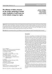
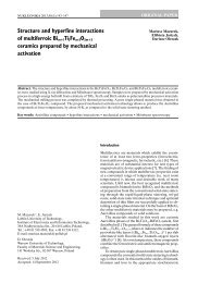
<strong>Electron</strong> <strong>beam</strong> <strong>flue</strong> <strong>gas</strong> <strong>treatment</strong><br />
<strong>process</strong> <strong>for</strong> <strong>purification</strong> <strong>of</strong> <strong>exhaust</strong><br />
<strong>gas</strong>es with high SO 2 concentrations<br />
Andrzej G. Chmielewski 1 , Janusz Licki 2<br />
1 Department <strong>of</strong> Nuclear Methods in Process Engineering,<br />
Institute <strong>of</strong><br />
Nuclear Chemistry and Technology,<br />
16 Dorodna Str., 03-195 Warsaw, , Poland.<br />
2 Department <strong>of</strong> Nuclear Energy,Institute <strong>of</strong> Atomic Energy,<br />
05-400 Otwock-Świerk, wierk, Poland.<br />
Tel: (+4822) 718 0144<br />
Fax: (+4822) 779 3888<br />
E-mail: licki@cyf.gov.pl<br />
INTERNATIONAL CONFERENCE ON RECENT DEVELOPMENTS AND APPLICATIONS<br />
OF NUCLEAR TECHNOLOGIES<br />
15-17 SEPTEMBER 2008, BIAŁOWIEśA, POLAND<br />
Main tasks<br />
The application <strong>of</strong> the electron-<strong>beam</strong> <strong>process</strong> <strong>for</strong><br />
<strong>purification</strong> <strong>of</strong> <strong>flue</strong> <strong>gas</strong>es with w<br />
high SO 2 concentrations<br />
was the purpose <strong>of</strong> this paper. The experimental<br />
studies were concentrated on the <strong>purification</strong> <strong>of</strong><br />
<strong>exhaust</strong> <strong>gas</strong>es<br />
1. from combustion <strong>of</strong> high sulphur<br />
coal<br />
heavy fuel oil<br />
2. and from copper smelter.<br />
The other aim was determination <strong>of</strong> the conditions <strong>for</strong><br />
obtaining the highest SO 2 and NO x removal efficiencies<br />
from above <strong>exhaust</strong> <strong>gas</strong>es.<br />
Table 1. Main parameters <strong>of</strong> industrial e-<strong>beam</strong> installations<br />
Parameter<br />
Flue <strong>gas</strong> flow rate<br />
Inlet <strong>flue</strong> <strong>gas</strong> temperature<br />
Inlet SO 2 concentration<br />
mg/Nm 3 5150<br />
2770<br />
2000<br />
concentration mg/Nm 3 820<br />
410<br />
600<br />
Inlet NO concentration<br />
x<br />
SO 2 removal efficiency<br />
NO x removal efficiency<br />
<strong>Electron</strong> <strong>beam</strong> parameters<br />
Unit<br />
Nm 3 /h<br />
0 C<br />
%<br />
%<br />
Chengdu<br />
TPP<br />
China<br />
300 000<br />
150<br />
80<br />
18<br />
800 keV,<br />
320 kWx2<br />
Hangzhou<br />
TPP<br />
China<br />
305 400<br />
145<br />
85<br />
55<br />
800 keV,<br />
320 kWx2<br />
Pomorzany<br />
EPS<br />
Poland<br />
270 000<br />
140<br />
90<br />
70<br />
700 keV,<br />
260 kWx4<br />
1
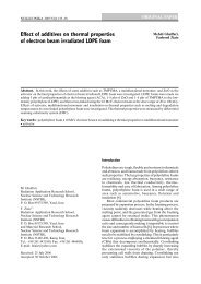
Fig. 1. Technological scheme <strong>of</strong> the industrial plant at EPS Pomorzany<br />
Fig. 2. Schematic flow diagram <strong>of</strong> the pilot plant at TPP Kawęczyn<br />
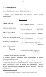
Fig. 3. Flow diagram <strong>of</strong> INCT laboratory plant equipped with stand <strong>for</strong> burning <strong>of</strong> mazout C-3.<br />
1. thermostated fuel oil<br />
2. oil burner<br />
3. particulate and soot filters<br />
4. orifice<br />
5. dosage <strong>of</strong> water vapour<br />
6. <strong>gas</strong> sampling point - <strong>process</strong> inlet<br />
7. ammonia injection<br />
8. <strong>process</strong> vessel<br />
9. electron <strong>beam</strong> accelerator<br />
10. retention chamber<br />
11. bag filter<br />
12. <strong>gas</strong> sampling point – <strong>process</strong> outlet<br />
13. induced - draught fan<br />
14. stack<br />
15. concrete shielding wall<br />
16. concrete shielding door<br />
2
Fig. 4. Flow diagram <strong>of</strong> INCT laboratory plant with <strong>gas</strong>-fired boilers<br />
1. two <strong>gas</strong>-fired boilers,<br />
2. orifice,<br />
3. SO2 dosage,<br />
4. NO dosage,<br />
5. water vapour dosage,<br />
6. <strong>gas</strong> sampling device,<br />
7. NH3, dosage,<br />
8. irradiation chamber,<br />
9. electron accelerator,<br />
10. retention chamber,<br />
11. bag filter,<br />
12. <strong>gas</strong> sampling device,<br />
13. draught fan,<br />
14. chimney,<br />
15. shielding walls,<br />
16. shielding door.<br />
α NH<br />
3<br />
Effect <strong>of</strong> absorbed dose<br />
Fig. 4 presents the dose dependence <strong>of</strong><br />
SO 2 and NO x removal efficiency.<br />
Dose dependence <strong>of</strong> SO 2 removal from <strong>gas</strong><br />
mixture with extemely high SO 2 concentration:<br />
SO 20 : 10% vol., H: 14.5% vol., α NH3 : 0.85-0.94,<br />
T inlet : 105-114°C<br />
Effect <strong>of</strong> ammonia stoichiometry<br />
3
Effect <strong>of</strong> <strong>gas</strong> temperature at inlet to proces vessel<br />
Effect <strong>of</strong> <strong>flue</strong> <strong>gas</strong> humidity<br />
Experimental conditions:<br />
SO 20 : 10 % vol, H: 14-15.5 % vol.,<br />
α NH3 : 085-0.95, T inlet : 105-116 °C<br />
Effect <strong>of</strong> inlet high SO 2 concentration<br />
SO 2 + *OH + M → HSO 3 + M<br />
HSO 3 + O 2 → SO 3 + HO 2<br />
*<br />
NO + HO 2* → NO 2 + *OH<br />
NO 2 + *OH + M → HNO 3 + M<br />
4
Conclusions<br />
Flue <strong>gas</strong>es from combustion <strong>of</strong> high sulphur fossil fuels can be effectively purified<br />
by the electron <strong>beam</strong> <strong>process</strong>. The SO 2 removal efficiency above 95 % and NO x<br />
removal above 75 % were obtained in the optimal <strong>treatment</strong> conditions. High<br />
removal efficiencies can be obtained by firstly properly controlling the temperature<br />
and humidity <strong>of</strong> <strong>flue</strong> <strong>gas</strong> in a dry bottom spray cooler. Then a near stoichiometric<br />
amount <strong>of</strong> NH 3 should be added to <strong>gas</strong> be<strong>for</strong>e its inlet to a <strong>process</strong> vessel.<br />
Thirdly, the mixture should be irradiated with adequate irradiation dose in the<br />
<strong>process</strong> vessel. The improvement in NO x removal is achieved by multi-stage<br />
irradiation and by adequate dose distribution between irradiation stages [5]. The<br />
<strong>gas</strong> humidity and temperature, ammonia stoichiometry and irradiation dose up 8<br />
kGy strongly in<strong>flue</strong>nce SO 2 removal efficiency. The synergistic effect <strong>of</strong> high SO 2<br />
concentration on NO x removal was indicated. The collected by-product was the<br />
mixture <strong>of</strong> ammonium sulphate and nitrate. The content <strong>of</strong> heavy metals in the byproduct<br />
was many times lower than the values acceptable <strong>for</strong> commercial<br />
fertilizer. In addition the <strong>for</strong>mation <strong>of</strong> a valuable product in large quantities might<br />
further reduce the operating cost <strong>of</strong> the EBFGT <strong>process</strong> depending on the market<br />
value <strong>of</strong> fertilizer by-product.<br />
Thank you <strong>for</strong> your<br />
attention!<br />
INTERNATIONAL CONFERENCE ON RECENT DEVELOPMENTS AND APPLICATIONS<br />
OF NUCLEAR TECHNOLOGIES<br />
15-17 SEPTEMBER 2008, BIAŁOWIEśA, POLAND<br />
5