IC-FR5000_IC-FR6000 Instruction Manual - Icom Australia
IC-FR5000_IC-FR6000 Instruction Manual - Icom Australia
IC-FR5000_IC-FR6000 Instruction Manual - Icom Australia

Create successful ePaper yourself
Turn your PDF publications into a flip-book with our unique Google optimized e-Paper software.
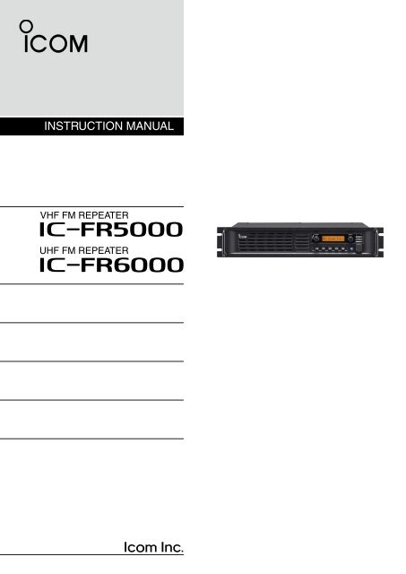
INSTRUCTION MANUAL<br />
VHF FM REPEATER<br />
i<strong>FR5000</strong><br />
UHF FM REPEATER<br />
i<strong>FR6000</strong>
IMPORTANT<br />
EXPL<strong>IC</strong>IT DEFINITIONS<br />
READ THIS INSTRUCTION MANUAL<br />
CAREFULLY before attempting to operate the repeater.<br />
SAVE THIS INSTRUCTION MANUAL– This<br />
manual contains important safety and operating instructions<br />
for the <strong>IC</strong>-<strong>FR5000</strong>/<strong>IC</strong>-<strong>FR6000</strong> vhf/uhf fm<br />
repeaters.<br />
WORD<br />
RWARNING<br />
CAUTION<br />
NOTE<br />
DEFINITION<br />
Personal injury, fire hazard or electric<br />
shock may occur.<br />
Equipment damage may occur.<br />
If disregarded, inconvenience only. No risk<br />
of personal injury, fire or electric shock.<br />
PRECAUTIONS<br />
R WARNING HIGH VOLTAGE! NEVER attach<br />
an antenna or internal antenna connector during<br />
transmission. This may result in an electrical shock or<br />
burn.<br />
R WARNING HIGH VOLTAGE! NEVER install<br />
the antenna at any place that person touch the<br />
antenna easily during transmission. This may result in<br />
an electrical shock or burn.<br />
R WARNING! NEVER apply AC to the DC<br />
power receptacle on the repeater rear panel. This<br />
could cause a fire or damage the repeater.<br />
R WARNING! NEVER apply more than 16 V DC,<br />
such as a 24 V battery, to the DC power receptacle<br />
on the repeater rear panel. This could cause a fire or<br />
damage the repeater.<br />
R CAUTION! NEVER let metal, wire or other objects<br />
touch any internal part or connectors on the rear<br />
panel of the repeater. This may result in an electric<br />
shock.<br />
R CAUTION! NEVER expose the repeater to<br />
rain, snow or any liquids.<br />
DO NOT use or place the repeater in areas with<br />
temperatures below –30°C (–22°F) or above<br />
+60°C (+140°F). Be aware that temperatures can exceed<br />
80°C (+176°F), resulting in permanent damage<br />
to the repeater if left there for extended periods.<br />
Place the repeater in a secure place to avoid inadvertent<br />
use by children.<br />
BE CAREFUL! The heatsink will become hot when<br />
operating the repeater continuously for long periods.<br />
BE CAREFUL! If a linear amplifier is connected, set<br />
the repeater’s RF output power to less than the linear<br />
amplifier’s maximum input level, otherwise, the linear<br />
amplifier will be damaged.<br />
Use <strong>Icom</strong> microphones only (optional). Other manufacturer’s<br />
microphones have different pin assignments,<br />
and connection to the repeater may damage<br />
the repeater.<br />
<strong>Icom</strong> optional equipment is designed for optimal performance<br />
when used with this repeater. We are not<br />
responsible for the repeater being damaged or any<br />
accident caused when using non-<strong>Icom</strong> optional equipment.<br />
For U.S.A. only<br />
CAUTION: Changes or modifications to this repeater,<br />
not expressly approved by <strong>Icom</strong> Inc., could void your<br />
authority to operate this repeater under FCC regulations.<br />
DO NOT place the repeater in excessively dusty environments<br />
or in direct sunlight.<br />
DO NOT put anything on top of the repeater. This will<br />
obstruct heat dissipation.<br />
<strong>Icom</strong>, <strong>Icom</strong> Inc. and the logo are registered trademarks<br />
of <strong>Icom</strong> Incorporated (Japan) in the United States, the United<br />
Kingdom, Germany, France, Spain, Russia and/or other<br />
countries.<br />
i
SAFETY TRAINING INFORMATION<br />
W ARN ING<br />
Your <strong>Icom</strong> radio generates RF electromagnetic<br />
energy during transmit<br />
mode. This radio is designed for and<br />
classified as “Occupational Use Only,”<br />
meaning it must be used only during<br />
the course of employment by individuals<br />
aware of the hazards, and the ways<br />
to minimize such hazards.<br />
This radio is NOT intended for use by<br />
the “General Population” in an uncontrolled<br />
environment.<br />
CAUTION<br />
To ensure that your exposure to RF<br />
electromagnetic energy is within the<br />
FCC allowable limits for occupational<br />
use, always adhere to the following<br />
guidelines:<br />
• DO NOT operate the radio without a proper antenna<br />
attached, as this may damage the radio and may<br />
also cause you to exceed FCC RF exposure limits.<br />
A proper antenna is the antenna supplied with this<br />
radio by the manufacturer or an antenna specifically<br />
authorized by the manufacturer for use with this radio.<br />
• DO NOT transmit for more than 50% of total radio<br />
use time (“50% duty cycle”). Transmitting more than<br />
50% of the time can cause FCC RF exposure compliance<br />
requirements to be exceeded. The radio is<br />
transmitting when the “TX indicator” lights red. You<br />
can cause the radio to transmit by pressing the “PTT”<br />
switch.<br />
Electromagnetic Interference/Compatibility<br />
During transmissions, your <strong>Icom</strong> radio generates RF<br />
energy that can possibly cause interference with other<br />
devices or systems. To avoid such interference, turn<br />
off the radio in areas where signs are posted to do<br />
so. DO NOT operate the transmitter in areas that are<br />
sensitive to electromagnetic radiation such as hospitals,<br />
aircraft, and blasting sites.<br />
FOR CLASS B UNINTENTIONAL RADIATORS<br />
This equipment has been tested and found to comply with<br />
the limits for a Class B digital device, pursuant to part 15<br />
of the FCC Rules. These limits are designed to provide<br />
reasonable protection against harmful interference in a<br />
residential installation. This equipment generates, uses and<br />
can radiate radio frequency energy and, if not installed and<br />
used in accordance with the instructions, may cause harmful<br />
interference to radio communications. However, there is<br />
no guarantee that interference will not occur in a particular<br />
installation.<br />
If this equipment does cause harmful interference to radio<br />
or television reception, which can be determined by turning<br />
the equipment off and on, the user is encouraged to try<br />
to correct the interference by one or more of the following<br />
measures:<br />
• Reorient or relocate the receiving antenna.<br />
• Increase the separation between the equipment and<br />
receiver.<br />
• Connect the equipment into an outlet on a circuit different<br />
from that to which the receiver is connected.<br />
• Consult the dealer or an experienced radio/TV technician<br />
for help.<br />
ii
KEY SEAL<br />
FORWARD<br />
Thank you for purchasing this <strong>Icom</strong> repeater. The<br />
<strong>IC</strong>-<strong>FR5000</strong>/<strong>IC</strong>-<strong>FR6000</strong> vhf/uhf fm repeaters is designed<br />
and built with <strong>Icom</strong>’s state of the art technology<br />
and craftsmanship. With proper care, this product<br />
should provide you with years of trouble-free operation.<br />
SUPPLIED ACCESSORIES<br />
The following accessories are supplied.<br />
Handles<br />
For handles attachment<br />
Spacers<br />
We want to take a couple of moments of your time to<br />
thank you for making the <strong>IC</strong>-<strong>FR5000</strong>/<strong>IC</strong>-<strong>FR6000</strong> your<br />
repeater of choice, and hope you agree with <strong>Icom</strong>’<br />
s philosophy of “technology first.” Many hours of research<br />
and development went into the design of your<br />
<strong>IC</strong>-<strong>FR5000</strong>/<strong>IC</strong>-<strong>FR6000</strong>.<br />
D FEATURES<br />
m Up to 2 channels operation<br />
You can install a channel extension module (optional<br />
UR-<strong>FR5000</strong>/UR-<strong>FR6000</strong>) into a repeater. 2<br />
channels can be operated as the repeater when a<br />
channel extension module is installed.<br />
m Built-in 5-Tone, DTMF encoder & decoder<br />
Multiple signaling systems are equipped as standard.<br />
These systems are fully compatible with<br />
<strong>Icom</strong> F-series radios.<br />
m DTMF remote control capability<br />
You can control the repeater from a remote location<br />
over the air or over a phone line with DTMF.<br />
m D-Sub 25 pin ACC port equipped<br />
You can use the optional equipment via the D-sub<br />
25 pin ACC port equipped on the repeater’s rear<br />
panel.<br />
m Other features<br />
- Wide frequency coverage (136 to 174 MHz, 400<br />
to 470 MHz, 450 to 512/520 MHz)<br />
- PC programmable<br />
- 19 inch rack mount<br />
- Optional Voice Scrambler Unit (UT-109R/<br />
UT-110R) for base operating mode<br />
DC power cable<br />
Screws<br />
Function name stickers*<br />
* Used for labelling the programmable<br />
function keys according<br />
to their assinged functions.<br />
iii
TABLE OF CONTENTS<br />
IMPORTANT............................................................... i<br />
EXPL<strong>IC</strong>IT DEFINITIONS............................................ i<br />
PRECAUTIONS.......................................................... i<br />
SAFETY TRAINING INFORMATION......................... ii<br />
FOR CLASS B UNINTENTIONAL RADIATORS...... ii<br />
FORWARD................................................................ iii<br />
SUPPLIED ACCESSORIES..................................... iii<br />
TABLE OF CONTENTS............................................ iv<br />
1 PANEL DESCRIPTION.............................. 1–3<br />
n Front panel......................................................... 1<br />
D Function display............................................. 2<br />
n Rear panel......................................................... 2<br />
D Accessory connector..................................... 3<br />
2 INSTALLATION AND CONNECTIONS..... 4–6<br />
n Unpacking.......................................................... 4<br />
n Selecting a location............................................ 4<br />
n Antenna connection........................................... 4<br />
n Front panel connection...................................... 5<br />
n Rear panel connection....................................... 5<br />
n Power supply connection................................... 6<br />
n Mounting the repeater........................................ 6<br />
D Using the supplied handle............................. 6<br />
3 OPERATION.................................................. 7<br />
n Receiving and transmitting................................ 7<br />
D Repeater operation........................................ 7<br />
D Base station operation................................... 7<br />
4 MAINTENANCE............................................ 8<br />
n Troubleshooting.................................................. 8<br />
n Fuse replacement.............................................. 8<br />
D Line fuse replacement................................... 8<br />
5 OPTIONS....................................................... 9<br />
6 ABOUT VO<strong>IC</strong>E CODING TECHNOLOGY.... 10<br />
1<br />
2<br />
3<br />
4<br />
5<br />
6<br />
7<br />
8<br />
9<br />
10<br />
11<br />
12<br />
13<br />
14<br />
15<br />
16<br />
17<br />
18<br />
19<br />
20<br />
21<br />
iv
1 PANEL DESCRIPTION<br />
n Front panel<br />
Function<br />
q w display e<br />
r<br />
t<br />
y<br />
P0 P1 P2 P3 P4<br />
q INTERNAL SPEAKER<br />
Monitors received signals.<br />
w VOLUME CONTROL [VOLUME] (p. 7)<br />
Adjusts the audio output level.<br />
e SELECTOR DIAL [SELECT]<br />
Rotate to adjust the squelch threshold level, select<br />
the operating channel. (Depending on the preprogrammed<br />
condition.)<br />
r POWER IND<strong>IC</strong>ATOR [POWER]<br />
➥ Lights green at ‘A’ module's indicator while the<br />
repeater power is turned ON.<br />
When a channel extension module is installed:<br />
➥ Lights green at the selected module indicator<br />
(‘A’ or ‘B’) while the repeater power is turned<br />
ON.<br />
➥ Lights orange at the un-selected module indicator<br />
(‘A’ or ‘B’) while the repeater power is turned<br />
ON.<br />
t TRANSMIT IND<strong>IC</strong>ATOR [TX]<br />
Lights red while transmitting.<br />
y BUSY IND<strong>IC</strong>ATOR [BUSY]<br />
Lights green while receiving a signal or when the<br />
noise squelch is open.<br />
About [PWR], [TX] and [BUSY] indicators:<br />
‘A’ and ‘B’ modules indicators are available for<br />
these indications. ‘A’ module's indicator correspond<br />
to the original module, and ‘B’ module's indicator<br />
correspond to an extended module.<br />
u M<strong>IC</strong>ROPHONE CONNECTOR [M<strong>IC</strong>]<br />
This 8-pin modular jack accepts the optional microphone.<br />
KEEP the [M<strong>IC</strong>] connector cover attached to the<br />
repeater when the optional microphone is not<br />
used.<br />
i<br />
o<br />
q<br />
q +8 V DC output (Max. 15 mA)<br />
w Output port for PC programming<br />
e NC<br />
r M PTT (Input port for TX control)<br />
t Microphone ground<br />
y Microphone input<br />
u Ground<br />
i Input port for PC programming<br />
i POWER SWITCH [POWER]<br />
➥ Push to turn the repeater power ON.<br />
➥ Push and hold for 3 sec. to turn the repeater<br />
power OFF.<br />
When a channel extension module is installed:<br />
➥ While the repeater power is turned ON, push<br />
to select the desired module to operate the repeater<br />
as the base station.<br />
• The power indicator of the selected module unit<br />
lights green.<br />
o DEALER-PROGRAMMABLE KEYS<br />
Desired functions can be programmed independently<br />
by your dealer.<br />
Ask your dealer for details.<br />
• Because these keys are programmable, the functions<br />
of these keys are unique to each unit.<br />
i<br />
u<br />
1
PANEL DESCRIPTION<br />
1<br />
D Function display<br />
q w e r t<br />
<strong>IC</strong>OM<br />
Inc.<br />
y<br />
q SIGNAL STRENGTH IND<strong>IC</strong>ATOR<br />
Indicates relative signal strength level.<br />
w LOW POWER IND<strong>IC</strong>ATOR<br />
Appears when low output power is selected.<br />
e AUDIBLE IND<strong>IC</strong>ATOR<br />
Appears when the channel is in the ‘audible’ (unmute)<br />
condition.<br />
n Rear panel<br />
The optional channel extention module can be installed.<br />
Ask your dealer for details.<br />
q EXTERNAL SPEAKER CONNECTOR [SP]<br />
Connect the optional SP-22.<br />
w RECEIVE ANTENNA CONNECTOR [RX]<br />
Connects a receive antenna (impedance: 50 ˘)<br />
and inputs receiving signals.<br />
e ACCESSORY CONNECTOR [ACC]<br />
Connects to the accessory connector.<br />
• See pgs. 3 for accessory connector information.<br />
r COMPANDER IND<strong>IC</strong>ATOR<br />
Appears when the compander function is activated.<br />
t SCRAMBLER/ENCRYPTION IND<strong>IC</strong>ATOR<br />
Appears when the voice scrambler/encryption<br />
function is activated.<br />
y ALPHANUMER<strong>IC</strong> DISPLAY<br />
Shows a variety of text or code information.<br />
q w e r t<br />
r DC POWER RECEPTACLE<br />
Connects the supplied DC power cable from this<br />
connector to an external 13.6 V DC power supply.<br />
t TRANSMIT ANTENNA CONNECTOR [TX]<br />
Connects a transmit antenna (impedance: 50 ˘)<br />
and outputs transmit signals.<br />
1<br />
2<br />
3<br />
4<br />
5<br />
6<br />
7<br />
8<br />
9<br />
10<br />
11<br />
12<br />
13<br />
14<br />
15<br />
16<br />
17<br />
18<br />
19<br />
20<br />
21
1 PANEL DESCRIPTION<br />
D Accessory connector<br />
!4 @5<br />
q !3<br />
Pin No.<br />
Pin Name<br />
Description<br />
Specification<br />
1<br />
NC<br />
No connection<br />
—<br />
2<br />
TXD<br />
Output terminal for serial communication data.<br />
—<br />
3<br />
RXD<br />
Input terminal for serial communication data.<br />
—<br />
4<br />
RTS<br />
Output terminal for request-to-send data.<br />
—<br />
5<br />
CTS<br />
Input terminal for clear-to-send data.<br />
—<br />
6<br />
NC<br />
No connection<br />
—<br />
7<br />
GND<br />
Serial/digital signal ground<br />
—<br />
8<br />
MOD IN<br />
Modulator input from an external terminal unit.<br />
Input level: 300 mV rms<br />
9<br />
DISC OUT<br />
Output terminal for AF signals from the AF detector circuit.<br />
Output level is fixed, regardless of [AF] control.<br />
Output level: 300 mV rms<br />
10<br />
EXT. D/A<br />
The desired function can be assigned.*<br />
(Default: Null)<br />
—<br />
11<br />
VCC<br />
13.6 V DC output<br />
Output current: Less than 1 A<br />
12<br />
EXT. A/D<br />
Customize A/D input (Not used)<br />
—<br />
13<br />
NC<br />
No connection<br />
—<br />
14<br />
GND<br />
Ground<br />
—<br />
15<br />
EXT.I/O 15<br />
The desired function can be assigned.*<br />
(Default: Null)<br />
+5 V pull up, Active=L<br />
16<br />
EXT.I/O 16<br />
The desired function can be assigned.*<br />
(Default: P0 Monitor Output)<br />
+5 V pull up, Active=L<br />
17<br />
EXT.I/O 17<br />
The desired function can be assigned.*<br />
(Default: Busy Output)<br />
+5 V pull up, Active=L<br />
18<br />
EXT.I/O 18<br />
The desired function can be assigned.*<br />
(Default: Null)<br />
+5 V pull up, Active=L<br />
19<br />
EXT.I/O 19<br />
The desired function can be assigned.*<br />
(Default: EPTT Input)<br />
+5 V pull up, Active=L<br />
20<br />
DATA IN<br />
Input terminal for data.<br />
—<br />
21<br />
EXT.I/O 21<br />
The desired function can be assigned.*<br />
(Default: Analog Audible Output)<br />
+5 V pull up, Active=L<br />
22<br />
AF OUT<br />
The AF detector Output.<br />
—<br />
23<br />
EXT.I/O 23<br />
The desired function can be assigned.*<br />
(Default: Mic Mute Output)<br />
+5 V pull up, Active=L<br />
24<br />
EXT.I/O 24<br />
The desired function can be assigned.*<br />
(Default: Null)<br />
+5 V pull up, Active=L<br />
25<br />
EXT.I/O 25<br />
The desired function can be assigned.*<br />
(Default: Mic Hanger Output)<br />
+5 V pull up, Active=L<br />
* The desired function can be assigned using the optional CS-<strong>FR5000</strong> cloning software. Ask your dealer for details.<br />
3
INSTALLATION AND CONNECTIONS<br />
2<br />
n Unpacking<br />
After unpacking, immediately report any damage to<br />
the delivering carrier or dealer. Keep the shipping cartons.<br />
For a description and a diagram of accessory equipment<br />
included with the repeater, see ‘SUPPLIED AC-<br />
CESSORIES’ on p. iii of this manual.<br />
n Antenna connection<br />
For radio communications, the antenna is a critical<br />
component, along with output power and sensitivity.<br />
Select antenna(s), such as a well-matched 50 ˘ antenna,<br />
and feedline. 1.5:1 or better of Voltage Standing<br />
Wave Ratio (VSWR) is recommended for desired<br />
band. Of course, the transmission line should be a<br />
coaxial cable.<br />
n Selecting a location<br />
Select a location for the repeater that allows adequate<br />
air circulation, free from extreme heat, cold, or vibrations,<br />
and away from TV sets, TV antenna elements,<br />
radios and other electromagnetic sources.<br />
TYPE-N CONNECTOR INSTALLATION EXAMPLE<br />
q<br />
w<br />
e<br />
r<br />
Nut Rubber gasket<br />
15 mm<br />
Washer<br />
Clamp<br />
Center<br />
conductor<br />
3 mm<br />
6 mm<br />
Solder hole<br />
No space<br />
Be sure the center conductor is<br />
the same height as the plug body.<br />
CAUTION: Protect repeater from lightning by using<br />
a lightning arrestor.<br />
NOTE: There are many publications that describe<br />
proper antennas and their installation. Check with<br />
your local dealer for more information and recommendations.<br />
Slide the nut, flat washer, rubber gasket and clamp over the coaxial<br />
cable, then cut the end of the cable evenly.<br />
Strip the cable and fold the braid back over the clamp.<br />
Soft solder the center conductor. Install the center conductor pin and<br />
solder it.<br />
Carefully slide the plug body into place aligning the center conductor<br />
pin on the cable. Tighten the nut onto the plug body.<br />
15 mm ( 19 ⁄32 in) 6 mm ( 1 ⁄4 in) 3 mm ( 1 ⁄8 in)<br />
1<br />
2<br />
3<br />
4<br />
5<br />
6<br />
7<br />
8<br />
9<br />
10<br />
11<br />
12<br />
13<br />
14<br />
15<br />
16<br />
17<br />
18<br />
19<br />
20<br />
21
2 INSTALLATION AND CONNECTIONS<br />
n Front panel connection<br />
P0 P1 P2 P3 P4<br />
HM-152 HAND<br />
M<strong>IC</strong>ROPHONE<br />
(optional)<br />
SM-25 DESKTOP<br />
M<strong>IC</strong>ROPHONE<br />
(optional)<br />
M<strong>IC</strong>ROPHONE CONNECTOR (Front panel view)<br />
q<br />
i<br />
q +8 V DC output (Max. 10 mA)<br />
w Output port for PC programming<br />
e NC<br />
r M PTT (Input port for TX control)<br />
t Microphone ground<br />
y Microphone input<br />
u Ground<br />
i Input port for PC programming<br />
CAUTION: DO NOT short pin 1 to ground as this can<br />
damage the internal 8 V regulator. DC voltage is applied<br />
to pin 1 for microphone operation. Only <strong>Icom</strong> microphones<br />
are recommended.<br />
n Rear panel connection<br />
SP-22 EXTERNAL SPEAKER<br />
ACC CONNECTOR (p. 3)<br />
Used for external equipment control.<br />
Connect a 4 ˘ external speaker.<br />
[TX ANT] (p. 4)<br />
[RX ANT] (p. 4)<br />
R CAUTION! NEVER remove<br />
the fuse-holder from the DC<br />
power receptacle.<br />
R When you disconnect the<br />
DC power cable, take care<br />
no crack of your fingernail.<br />
w<br />
20 A<br />
fuses<br />
AC outlet<br />
AC cable<br />
DC power supply<br />
13.6 V; at least 20 A<br />
Red<br />
+<br />
Black<br />
_<br />
q Push<br />
Supplied<br />
DC power cable<br />
Red<br />
Black
INSTALLATION AND CONNECTIONS<br />
2<br />
n Power supply connection<br />
Make sure the repeater’s power is turned OFF when<br />
connecting a DC power cable.<br />
CAUTION: Voltages greater than 16 V DC will damage<br />
the repeater. Check the source voltage before<br />
connecting the power cable.<br />
n Mounting the repeater<br />
D Using the supplied handle<br />
The supplied handles are available for mounting the<br />
repeater into a 19 inch rack. The handles can be installed<br />
to the repeater’s front panel.<br />
q Attach the supplied handles to both sides of the repeater’s<br />
front panel with the spacers, then tighten<br />
the screws as below.<br />
Handle<br />
P0 P1 P2 P3 P4<br />
Spacer<br />
Screw<br />
w The completed installation should look like as<br />
below.<br />
P0 P1 P2 P3 P4<br />
1<br />
2<br />
3<br />
4<br />
5<br />
6<br />
7<br />
8<br />
9<br />
10<br />
11<br />
12<br />
13<br />
14<br />
15<br />
16<br />
17<br />
18<br />
19<br />
20<br />
21<br />
6
3<br />
OPERATION<br />
n Receiving and transmitting<br />
D Repeater operation<br />
Ask your dealer for details of the repeater’s programming.<br />
➥ When the power is turned ON, the [PWR] indicator<br />
lights green. (p. 1)<br />
➥ The [TX] and [BUSY] indicators light simultaneously<br />
while transmitting/receiving a signal.<br />
• The [TX] indicator lights red.<br />
• The [BUSY] indicator lights green.<br />
NOTE: A power amplifier protector is built-in to the<br />
repeater. The protector is activated when the repeater<br />
temperature becomes extremely high due<br />
to the frequently access to the repeater to reduce<br />
the transmit output power level. The output power<br />
will return to the normal level when the repeater<br />
has cooled down.<br />
D Base station operation<br />
Receiving<br />
q Push [POWER] to turn the power ON.<br />
w Set the audio and squelch levels.<br />
➥ Rotate [SELECT]* 1 fully counterclockwise in advance.<br />
➥ Rotate [VOLUME] to adjust the audio output<br />
level.<br />
➥ Rotate [SELECT]* 1 clockwise until the noise<br />
disappears.<br />
e Push [CH Up]* 2 or [CH Down]* 2 to select the desired<br />
channel.<br />
• When receiving a signal, the [BUSY] indicator lights<br />
green and audio is emitted from the speaker.<br />
• Further adjustment of [VOLUME] to a comfortable listening<br />
level may be necessary at this point.<br />
* 1 When the [SQL Level Up/Down] key function is assigned<br />
to [SELECT].<br />
* 2 When the [CH Up]/[CH Down] key functions are assigned.<br />
Transmitting<br />
q Take the microphone off hook.<br />
w Wait for the channel to become clear.<br />
e Push and hold [PTT] to transmit, then speak into<br />
the microphone at your normal voice level.<br />
r Release [PTT] to receive.<br />
IMPORTANT:<br />
To maximize the audio quality of the transmitted signal:<br />
(1) Pause briefly after pushing [PTT].<br />
(2) Hold the microphone 1 to 2 inch (2.5 to 5 cm) from<br />
your mouth, then speak into the microphone at a<br />
normal voice level.
MAINTENANCE<br />
4<br />
n Troubleshooting<br />
The following chart is designed to help correct problems<br />
which are not equipment malfunctions.<br />
If you are unable to locate the cause of a problem or<br />
solve it through the use of this chart, contact the nearest<br />
<strong>Icom</strong> Dealer or Service Center.<br />
PROBLEM POSSIBLE CAUSE SOLUTION REF.<br />
Power does not<br />
c o m e o n w h e n<br />
[ P O W E R ] i s<br />
pushed.<br />
• DC power cable is improperly connected.<br />
• Fuse is blown.<br />
• Re-connect the DC power cable correctly.<br />
• Check the cause, then replace the fuse with<br />
a spare one.<br />
pgs.<br />
5, 6<br />
p. 8<br />
No sounds from<br />
the speaker.<br />
Sensitivity is low<br />
and only strong<br />
signals are audible.<br />
Received signal<br />
cannot be understood.<br />
Output power is<br />
too low.<br />
No contact possible<br />
with another<br />
station.<br />
• Volume level is too low.<br />
• The squelch is closed.<br />
n Fuse replacement<br />
If a fuse blows or the repeater stops functioning, try to<br />
find the source of the problem, and then replace the<br />
damaged fuse with a new, rated fuse.<br />
D Line fuse replacement<br />
• The audio mute function is activated.<br />
• A selective call or squelch function is activated<br />
such as 5 tone call or tone squelch.<br />
• The front speaker is set to OFF.<br />
• Antenna feedline or the antenna connector<br />
has a poor contact or is short-circuited.<br />
• Optional voice scrambler is turned OFF.<br />
• Scrambler code is not set correctly.<br />
• Output power is set to Low.<br />
• Power amplifier protection circuit is activated.<br />
• The other station is using tone squelch.<br />
• While in base operating mode, the repeater<br />
is set to duplex.<br />
• Rotate [VOLUME] clockwise to obtain a suitable<br />
listening level.<br />
• While in base operating mode, rotate [SE-<br />
LECT] to counterclockwise to open the<br />
squelch. (When the [SQL Level Up/Down] key<br />
function is assigned to [SELECT].)<br />
• Push [MONI] (if assigned) to the audio mute<br />
function OFF<br />
• Turn the appropriate function OFF.<br />
• Turn the front speaker ON using the optional<br />
CS-<strong>FR5000</strong> cloning software. Ask your<br />
dealer for details.<br />
• Check and re-connect (or replace if necessary),<br />
the antenna feedline or antenna connector.<br />
• Turn the optional voice scrambler ON.<br />
• Reset the scrambler code.<br />
• Push [HIGH/LOW] (if assigned) to select the<br />
High power.<br />
• Cool down the repeater or stop accessing to<br />
the repeater until it has cooled down.<br />
• Turn the tone squelch function ON.<br />
• Set the repeater to simplex, when other transceiver<br />
is set to simplex.<br />
CAUTION: DISCONNECT the DC power cable<br />
from the repeater. Otherwise, there is danger of<br />
electric shock and/or equipment damage.<br />
Fuse rating: 20 A<br />
USE the 20 A fuse only.<br />
p. 7<br />
p. 7<br />
–<br />
–<br />
–<br />
p. 5<br />
–<br />
–<br />
–<br />
–<br />
–<br />
–<br />
<br />
1<br />
2<br />
3<br />
4<br />
5<br />
6<br />
7<br />
8<br />
9<br />
10<br />
11<br />
12<br />
13<br />
14<br />
15<br />
16<br />
17<br />
18<br />
19<br />
20<br />
21
5<br />
OPTIONS<br />
• SP-22 external speaker<br />
Compact and easy-to-install.<br />
Input impedance : 4 ˘<br />
Max. input power : 5 W<br />
• HM-152 hand microphone<br />
• SM-25 desktop microphone<br />
• UR-<strong>FR5000</strong>/UR-<strong>FR6000</strong> channel extension modules<br />
• UT-109R voice scrambler unit<br />
Non-rolling type (max. 32 codes).<br />
• UT-110R voice scrambler unit<br />
Rolling type (max. 1020 codes).<br />
* The scrambler systems of the UT-109R and UT-<br />
110R are not compatible with each other.<br />
Some options may not available in some countries.<br />
Please ask your dealer for details.
ABOUT VO<strong>IC</strong>E CODING TECHNOLOGY<br />
6<br />
The AMBE+2 voice coding Technology embodied in this<br />
product is protected by intellectual property rights including<br />
patent rights, copyrights and trade secrets of Digital Voice<br />
Systems, Inc. This voice coding Technology is licensed<br />
solely for use within this Communications Equipment. The<br />
user of this Technology is explicitly prohibited from attempting<br />
to extract, remove, decompile, reverse engineer, or<br />
disassemble the Object Code, or in any other way convert<br />
the Object Code into a human-readable form. U.S. Patent<br />
Nos. #5,870,405, #5,826,222, #5,754,974, #5,701,390,<br />
#5,715,365, #5,649,050, #5,630,011, #5,581,656,<br />
#5,517,511, #5,491,772, #5,247,579, #5,226,084 and<br />
#5,195,166.<br />
1<br />
2<br />
3<br />
4<br />
5<br />
6<br />
7<br />
8<br />
9<br />
10<br />
11<br />
12<br />
13<br />
14<br />
15<br />
16<br />
17<br />
18<br />
19<br />
20<br />
21<br />
10
A-6635H-1EX-w<br />
Printed in Japan<br />
© 2007–2008 <strong>Icom</strong> Inc.<br />
Printed on recycle paper with soy ink.<br />
1-1-32 Kamiminami, Hirano-ku, Osaka 547-0003, Japan