Leybold D65BCS, D40BCS, Instruction Manual - Ideal Vacuum ...
Leybold D65BCS, D40BCS, Instruction Manual - Ideal Vacuum ...
Leybold D65BCS, D40BCS, Instruction Manual - Ideal Vacuum ...
Create successful ePaper yourself
Turn your PDF publications into a flip-book with our unique Google optimized e-Paper software.
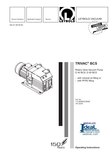
<strong>Vacuum</strong> Solutions Application Support Service LEYBOLD VACUUM<br />
GA 01.301/6.02<br />
TRIVAC ® BCS<br />
Rotary Vane <strong>Vacuum</strong> Pump<br />
D 40 BCS, D 65 BCS<br />
- with mineral oil filling or<br />
- with PFPE filling<br />
Cat. No.<br />
113 88/89/97/98/99<br />
154 52/54<br />
idealvac.com<br />
(505)872-0037<br />
idealvac.com<br />
Operating <strong>Instruction</strong>s
Contents<br />
Contents<br />
Page<br />
IMPORTANT SAFETY CONSIDERATIONS . . . 4<br />
1 Description . . . . . . . . . . . . . . . . . . . . . . . . . . 6<br />
1.1 Function . . . . . . . . . . . . . . . . . . . . . . . . . . . . . 7<br />
1.2 Lubricants . . . . . . . . . . . . . . . . . . . . . . . . . . . . 9<br />
1.3 Transportation . . . . . . . . . . . . . . . . . . . . . . . . . 9<br />
1.4 Supplied Equipment . . . . . . . . . . . . . . . . . . . . 9<br />
1.5 Spare Parts . . . . . . . . . . . . . . . . . . . . . . . . . . 10<br />
1.6 Accessories . . . . . . . . . . . . . . . . . . . . . . . . . . 10<br />
1.6.1 Standard Accessories and Lubricants . . . . . . 10<br />
1.6.2 TRIVAC System . . . . . . . . . . . . . . . . . . . . . . . 11<br />
1.7 Technical Data . . . . . . . . . . . . . . . . . . . . . . . . 12<br />
1.7.1 Motor Dependent Data . . . . . . . . . . . . . . . . . 13<br />
2 Operation . . . . . . . . . . . . . . . . . . . . . . . . . . . 14<br />
2.1 Installation . . . . . . . . . . . . . . . . . . . . . . . . . . . 14<br />
2.2 Connection to the System . . . . . . . . . . . . . . . 15<br />
2.3 Electrical Connections . . . . . . . . . . . . . . . . . . 16<br />
2.4 Start-up . . . . . . . . . . . . . . . . . . . . . . . . . . . . . 17<br />
2.4.1 Areas of Application . . . . . . . . . . . . . . . . . . . . 18<br />
2.4.2 Notes for Pumps with EExe II T3 Motors . . . . 18<br />
2.5 Operation . . . . . . . . . . . . . . . . . . . . . . . . . . . 19<br />
2.5.1 Pumping of Non-Condensable Gases . . . . . . 19<br />
2.5.2 Pumping of Condensable Gases and Vapours 19<br />
2.5.3 Operating Temperature . . . . . . . . . . . . . . . . . 19<br />
2.6 Switching Off/Shutdown . . . . . . . . . . . . . . . . . 20<br />
2.6.1 Shutdown through Monitoring Components . . 20<br />
2.6.2 Failure of the Control System or<br />
the Mains Power . . . . . . . . . . . . . . . . . . . . . . 20<br />
3 Maintenance . . . . . . . . . . . . . . . . . . . . . . . . 21<br />
3.1 Checking the Oil Level . . . . . . . . . . . . . . . . . . 21<br />
3.1.1 Checking the Condition of N 62 or<br />
HE 200 Oil . . . . . . . . . . . . . . . . . . . . . . . . . . 21<br />
3.2 Oil Change . . . . . . . . . . . . . . . . . . . . . . . . . . 22<br />
3.3 Cleaning the Dirt Trap . . . . . . . . . . . . . . . . . . 22<br />
3.4 Removing and Fitting the Internal Demister . . 23<br />
3.5 Disassembly and Reassembly of the<br />
Electric Motor . . . . . . . . . . . . . . . . . . . . . . . . 24<br />
3.6 Replacing the Outer Shaft Seal . . . . . . . . . . . 25<br />
3.7 Removing and Remounting the Pump Module 26<br />
3.7.1 Removing the Pump Module . . . . . . . . . . . . . 26<br />
3.7.2 Remounting the Pump Module . . . . . . . . . . . . 27<br />
3.8 <strong>Leybold</strong> Service . . . . . . . . . . . . . . . . . . . . . . . 28<br />
3.8.1 Waste Disposal of Used Pump Materials . . . . 28<br />
3.9 Storing the Pump . . . . . . . . . . . . . . . . . . . . . . 28<br />
3.10 Maintenance Plan . . . . . . . . . . . . . . . . . . . . . 29<br />
4 Troubleshooting . . . . . . . . . . . . . . . . . . . . . . 30<br />
EEC Declaration of Conformity . . . . . . . . . . 32<br />
We reserve the right to modify the design and the specified<br />
data. The illustrations are not binding.<br />
2<br />
GA 01.301/6.02 - 05/01
Note<br />
Warning<br />
Caution<br />
We strongly recommend that you read<br />
these Operating <strong>Instruction</strong>s with care so as<br />
to ensure optimum operation of the pump<br />
right from the start.<br />
Indicates procedures that must be strictly<br />
observed to prevent hazards to persons.<br />
Indicates procedures that must strictly be<br />
observed to prevent damage to, or destruction<br />
of the pump.<br />
Figures<br />
The references to diagrams, e.g. (1/2) consist of the Fig.<br />
No. and the Item No. in that order.<br />
<strong>Leybold</strong>-Service<br />
If a pump is returned to LEYBOLD, indicate whether the<br />
pump is free of substances damaging to health or<br />
whether it is contaminated.<br />
If it is contaminated also indicate the nature of the<br />
hazard. LEYBOLD must return any pumps without a<br />
„Declaration of Contamination“ to the sender’s address.<br />
Disposal of Waste Oil<br />
Owners of waste oil are entirely self-responsible for proper<br />
disposal of this waste.<br />
Waste oil from vacuum pumps must not be mixed with<br />
other substances or materials.<br />
Waste oil from vacuum pumps (<strong>Leybold</strong> oils which are<br />
based on mineral oils) which are subject to normal wear<br />
and which are contaminated due to the influence of oxygen<br />
in the air, high temperatures or mechanical wear<br />
must be disposed of through the locally available waste<br />
oil disposal system.<br />
Waste oil from vacuum pumps which is contaminated<br />
with other substances must be marked and stored in<br />
such a way that the type of contamination is apparent.<br />
This waste must be disposed of as special waste.<br />
European, national and regional regulations concerning<br />
waste disposal need to be observed. Waste must only be<br />
transported and disposed of by an approved waste disposal<br />
vendor.<br />
GA 01.301/6.02 - 05/01<br />
3
IMPORTANT SAFETY CONSIDERATIONS<br />
The <strong>Leybold</strong> TRIVAC BCS (PFPE) vacuum pump is designed for safe and efficient operation when used properly and<br />
in accordance with this manual. It is the responsibility of the user to carefully read and strictly observe all safety precautions<br />
described in this section and throughout the manual. This product must be operated and maintained by trained<br />
personnel only. Consult local, state, and national agencies regarding specific requirements and regulations.<br />
Address any further safety, operation and/or maintenance questions to your nearest <strong>Leybold</strong> <strong>Vacuum</strong> office.<br />
Warning<br />
Failure to observe the following precautions could result in serious personal injury:<br />
• Before beginning with any maintenance or service work on the TRIVAC BCS (PFPE), disconnect the<br />
pump from all power supplies.<br />
• Do not operate the pump with any of the covers removed. Serious injury may result.<br />
• If exhaust gases must be collected or contained, do not allow the exhaust line to become pressurised.<br />
• Make sure that the gas flow from the exhaust port is not blocked or restricted in any way.<br />
• The standard version of the TRIVAC BCS (PFPE) is not suited for operation in explosion hazard areas.<br />
Contact us before planning to use the pump under such circumstances.<br />
• Before starting up for the first time, the motor circuit (3 phase) must be equipped with a suitable<br />
protective motor switch. Please take note of the information in these Operating <strong>Instruction</strong>s or on the<br />
electric motor (wiring diagram).<br />
• The TRIVAC BCS (PFPE) is not suited for pumping of:<br />
- combustible and explosive gases or vapours<br />
- radioactive and toxic substances<br />
- pyrophorous substances.<br />
• Avoid exposing any part of the human body to the vacuum.<br />
• Never operate the TRIVAC BCS (PFPE) without a connected intake line or blank flange.<br />
• The location at which the TRIVAC BCS (PFPE) (including its accessories) is operated should be such<br />
that angles over 10° from the vertical are avoided.<br />
• The location of the TRIVAC BCS (PFPE) should be such that all controls are easily accessible.<br />
• Under certain ambient conditions the TRIVAC BCS (PFPE) may attain a temperature of over 80 °C<br />
(176 °F). There then exists the danger of receiving burns.<br />
Note the symbols on the pump pointing to the hazards, and in the case of a hot pump wear the required<br />
protective clothing.<br />
• Before pumping oxygen (or other highly reactive gases) at concentrations exceeding the concentration<br />
in the atmosphere (> 21 % for oxygen) it will be necessary to use a special pump. Such a pump will<br />
have to be modified and de-greased, and an inert special lubricant (like PFPE) must be used.<br />
4 GA 01.301/6.02 - 05/01
Warning<br />
• Before operating the TRIVAC BCS (PFPE) with atmospheric gas ballast (optional) check first compatibility<br />
with the pumped media so as to avoid hazardous conditions during operation right from the start.<br />
• Before commissioning the TRIVAC BCS (PFPE), make sure that the media which are to be pumped<br />
are compatible with each other so as to avoid hazardous situations.<br />
All relevant safety standards and regulations must be observed.<br />
• It is recommended to always operate the TRIVAC BCS (PFPE) with a suitable exhaust line which is properly<br />
connected. It must slope down and away from the pump.<br />
• When moving the TRIVAC BCS (PFPE) always use the allowed means.<br />
A lifting eye is provided as standard on the pump.<br />
Caution<br />
Failure to observe the following precautions could result in damage to the pump:<br />
• Do not allow the ingestion of small objects (screws, nuts, washers, pieces of wire, etc.)<br />
through the inlet port. Always use the screen which is supplied with every pump.<br />
• Do not use the pump for applications that produce abrasive or adhesive powders or<br />
condensable vapours that can leave adhesive or high viscosity deposits. Please contact <strong>Leybold</strong> Sales<br />
or Service to select a suitable separator. Also pease contact <strong>Leybold</strong> Sales or Service when planning<br />
to pump vapours other than water vapour.<br />
• This pump is suited for pumping water vapour within the specified water vapour tolerance limits.<br />
• Avoid vapours that can condense into liquids upon compression inside the pump, if these substances<br />
exceed the vapour tolerance of the pump (> 25 mbar for water vapour).<br />
• Before pumping vapours, the TRIVAC BCS (PFPE) should have attained its operating temperature, and<br />
the gas ballast should be set to position I (position 0 = closed, position I = max. water vapour tolerance,<br />
25 mbar).<br />
The pump will have attained its operating temperature about 30 minutes after starting the pump. During<br />
this time the pump should be separated from the process, by a valve in the intake line, for example.<br />
• In the case of wet processes we recommend the installation of liquid separators upstream and downstream<br />
of the pump as well as the use of the gas ballast.<br />
• The exhaust line should be laid so that it slopes down and away from the pump so as to prevent condensate<br />
from backstreaming into the pump. For this preferably use the flange on the side of the motor.<br />
• The entry of particles and fluids must be avoided under all circumstances.<br />
• Reactive or aggressive substances in the pump chamber may impair the operating oil or modify it.<br />
In addition, such substances may be incompatible with the materials of the pump (Viton, grey cast iron,<br />
aluminium, steel, resins, glass etc.).<br />
• Corrosion, deposits and cracking of oil within the pump are not allowed.<br />
Note<br />
This information will help the operator to obtain the best performance from the equipment:<br />
• Normal amounts of humidity within the range of the pump’s vapour tolerance will not significantly affect<br />
pump performance when the gas ballast is active. Preferably use the exhaust flange located on the side<br />
of the motor.<br />
Caution:<br />
In the case of custom pumps (with a Cat. No. deviating from the Cat No. stated in the<br />
EC Declaration of Conformity) please note the information provided on a separate sheet.<br />
GA 01.301/6.02 - 05/01<br />
5
Description<br />
Fig. 1 TRIVAC BCS pump with accessories<br />
1 Description<br />
TRIVAC BCS pumps are oil-sealed rotary vane pumps.<br />
The TRIVAC D 40 BCS and D 65 BCS are dual-stage<br />
pumps. The number in the type designation (40 or 65)<br />
indicates the pumping speed in m 3 · h -1 .<br />
The TRIVAC BCS-PFPE have been prepared especially<br />
for operation with perfluoropolyther.<br />
TRIVAC BCS pumps can pump gases and vapours, and<br />
evacuate vessels or vacuum systems in the fine vacuum<br />
range.<br />
They have been designed particularly for use in connection<br />
with corrosive or aggressive media. Moreover, the<br />
pump has been prepared for the installation of an electric<br />
monitoring facility. <strong>Leybold</strong> have developed for the<br />
TRIVAC BCS a range of accessories which considerably<br />
extend the range of applications for this kind of pump.<br />
These accessories which in connection with the TRIVAC<br />
BCS vacuum pump make up the TRIVAC system, are<br />
described briefly in Chapter 1.6.<br />
The drive motor of the TRIVAC BCS is directly flanged to<br />
the pump at the coupling housing. The pump and motor<br />
shafts are directly connected by a flexible coupling. The<br />
bearing points of the pump module are force lubricated<br />
sliding bearings. All controls as well as the oil-level glass<br />
and the nameplate are arranged on the front. All connections<br />
are to be found at the sides of the pump. The oillevel<br />
glass is provided with prisms for better observation<br />
of the oil level.<br />
The pump module consists of assembly parts which are<br />
pin-fitted so as to allow easy disassembly and reassembly.<br />
The pump module can be easily removed without<br />
special tools.<br />
Warning<br />
Those of standard design are not suitable<br />
for pumping greater than atmospheric concentrations<br />
of oxygen.<br />
Before pumping oxygen (or other highly<br />
reactive gases) at concentrations exceeding<br />
the concentration in the atmosphere<br />
(> 21 % for oxygen) it will be necessary to<br />
use a special pump. Such a pump will have<br />
to be modified and de-greased, and an inert<br />
special lubricant (like PFPE) must be used.<br />
6 GA 01.301/6.02 - 05/01
Description<br />
Key to Fig. 2<br />
1 Intake port<br />
2 Dirt trap<br />
3 Anti-suckback valve<br />
4 Intake channel<br />
5 Vanes<br />
6 Pump chamber<br />
7 Rotor<br />
8 Cover plate, connection for inert gas ballast<br />
9 Exhaust channel<br />
10 Exhaust valve<br />
11 Internal demister<br />
12 Spring buckles<br />
13 Cover plate, connection for oil filter<br />
Fig. 2 Sectional drawing of the TRIVAC BCS<br />
1.1 Function<br />
The rotor (2/7), mounted eccentrically in the pump housing<br />
(2/6), has two radially sliding vanes (2/5) which divide<br />
the pump chamber into several compartments. The<br />
volume of each compartment changes periodically with<br />
the rotation of the rotor.<br />
As a result, gas is sucked in at the intake port (2/1). The<br />
gas passes through the dirt trap sieve (2/2), flows past<br />
the open anti-suckback valve (2/3) and then enters the<br />
pump chamber. In the pump chamber, the gas is passed<br />
on and compressed, after the inlet aperture is closed by<br />
the vane.<br />
The oil injected into the pump chamber is used for sealing<br />
and lubricating. The slap noise of the oil in the pump<br />
which usually occurs when attaining the ultimate pressure<br />
is prevented by admitting a very small amount of air<br />
into the pump chamber.<br />
The compressed gas in the pump chamber is ejected<br />
through the exhaust valve (2/10). The oil entrained in the<br />
gas is coarsely trapped in the internal demister (2/11);<br />
there the oil is also freed of mechanical impurities. The<br />
TRIVAC BCS PFPE pumps do not have an internal<br />
demister. The gas leaves the TRIVAC BCS-PFPE<br />
through the exhaust port.<br />
During compression, a controlled amount of air – the socalled<br />
gas ballast – can be allowed to enter the pump<br />
chamber by opening the gas ballast valve. The gas ballast<br />
stops condensation of vapours in the pump chamber<br />
up to the limit of the water vapour tolerance as specified<br />
in the technical data for the pump.<br />
GA 01.301/6.02 - 05/01<br />
The gas ballast valve is opened (position I) and closed<br />
(position 0) by turning the gas ballast knob (7/5) on the<br />
front.<br />
The gas ballast facility of the TRIVAC BCS pump has<br />
been prepared for connecting the inert gas system IGS,<br />
see Chapter 1.6.2.<br />
To enable the TRIVAC BCS to be used at intake<br />
pressures as high as 1,000 mbar, a special lubricating<br />
system was developed featuring force-lubrication of the<br />
sliding bearings.<br />
An oil pump (3/6) pumps the oil from the oil reservoir<br />
(3/5) into a pressure-lubrication system which supplies<br />
oil to all bearing points (3/2). From there the oil enters the<br />
pump chamber area (3/4) of the vacuum pump.<br />
The oil pump is fitted in the front end plate on the coupling<br />
side of the pump module. The oil suction line is placed<br />
low, resulting in a large usable oil reservoir.<br />
The oil is separated from the gas in the TRIVAC BCS in<br />
two steps as described above. First, small droplets are<br />
coalesced into large drops in the internal demister (2/11)<br />
fitted above the exhaust valve (2/10). Then, the large<br />
drops fall into the oil reservoir as the exhaust gas is<br />
diverted by the inner walls of the oil case. Thus a low loss<br />
of oil is obtained. This and the large usable oil reservoir<br />
ensure long intervals between oil changes even at high<br />
intake pressures.<br />
7
Description<br />
Key to Fig. 3<br />
1 Accessories<br />
2 Bearings<br />
3 Non-return valve<br />
4 Pump chamber of the TRIVAC<br />
5 Oil reservoir<br />
6 Oil pump<br />
Fig. 3 Schematic of the lubricating system<br />
Fig. 4 Hydropneumatic anti-suckback valve<br />
Key to Fig. 4<br />
1 Oil reservoir 5 Valve seat<br />
2 Spring 6 Valve disk<br />
3 Control piston 7 Gas inlet<br />
4 Anti-suckback piston<br />
The vacuum is maintained by the TRIVAC BCS through<br />
an integrated hydropneumatic anti-suckback valve (2/3)<br />
which is controlled via the oil pressure.<br />
During operation of the TRIVAC BCS the control piston<br />
(4/3) remains sealed against a spring (4/2) by the oil<br />
pressure. The valve disc (4/6) of the anti-suckback valve<br />
is held at the lower position by its own weight (valve<br />
open). When the pump stops (because it has been switched<br />
off or because of a failure), the oil pressure drops<br />
and the spring (4/2) presses the control piston (4/3) up.<br />
Thus a connection is provided between the oil case or<br />
the oil reservoir (4/1) and the piston (4/4) of the antisuckback<br />
valve.<br />
Due to the pressure difference between the oil case and<br />
the intake port the oil presses the piston (4/4) up and the<br />
valve plate (4/6) against the valve seat (4/5). The quantity<br />
of oil in the oil reservoir (4/1) prevents the entry of air<br />
into the intake port (2/1) at the beginning of this process.<br />
After the oil has flowed out from the reservoir and when<br />
the valve plate rests on the valve seat, air follows in,<br />
which vents the pump chamber and forces the valve disc<br />
(4/6) against its seat.This effectively prevents backstreaming<br />
of oil or oil vapours. The anti-suckback valve (2/3)<br />
operates independently of the operating mode of the<br />
pump, i.e. also with gas ballast.<br />
All aluminium surfaces of the TRIVAC BCS are surface<br />
protected and thus particularly capable of resisting<br />
aggressive chemicals. A thermocouple has been incorporated<br />
in the pump which is used in connection with the<br />
optional electrical monitoring facility. The thermocouple<br />
may be accessed through the built-in connector (7/8).<br />
Via a second oil fill opening, an exhaust line may be<br />
connected for venting the oil case when using the inert<br />
gas purging facility.<br />
8 GA 01.301/6.02 - 05/01
Description<br />
1.2 Lubricants<br />
The standard TRIVAC BCS pumps are either ready for<br />
operation with mineral oil or with the special lubricant,<br />
perfluoropolyther (PFPE).<br />
If mineral oil and PFPE come into contact they will emulsify.<br />
That’s why the pumps must only be run with the type<br />
of lubricant specified for the pump. If you want to change<br />
the type of lubricant LEYBOLD should do the change.<br />
In case of operation with mineral oil we recommend our<br />
vacuum pump oil N 62.<br />
In case of operation with PFPE we recommend our<br />
vacuum pump oil NC 1/14.<br />
When handling PFPE you should observe the following:<br />
Warning<br />
During thermal decomposition at temperatures<br />
over 290 °C toxic and corrosive gases<br />
are released. When handling PFPE keep it<br />
way from open fires. Do not smoke in the<br />
work area.<br />
Touch the inner sections of the pumps only while wearing<br />
clean gloves, and use clean tools;<br />
Do the necessary work in clean and dry rooms;<br />
After having removed the pump from its packaging, start<br />
it up as quickly as possible;<br />
While working on the pump, do not eat, drink or smoke.<br />
As cleaning agents solvents based on fluoroalkane<br />
compounds may be used.<br />
When planning to use the pump with a different kind of<br />
lubricant contact us first.<br />
The Operating <strong>Instruction</strong>s GA 07.009 “PFPE for<br />
<strong>Vacuum</strong> Pumps“ will be enclosed with all TRIVAC<br />
BCS pumps. Observe the handling notes for PFPE<br />
collected in these Operating <strong>Instruction</strong>s.<br />
Given in Operating <strong>Instruction</strong>s GA 07.009 are also the<br />
deviating specifications which apply to TRIVAC BCS<br />
pumps operated with PFPE.<br />
Caution: In the case of custom pumps (with a Cat.<br />
No. deviating from the Cat No. stated in the EC<br />
Declaration of Conformity) please note the information<br />
provided on a separate sheet.<br />
1.3 Transportation<br />
Warning<br />
• Pumps which are filled with operating<br />
agents must only be moved while standing<br />
upright. Otherwise oil may escape. Avoid<br />
any other orientations during transport.<br />
• Check the pump for the presence of any<br />
oil leaks, since there exists the danger that<br />
someone may slip on spilt oil.<br />
• When lifting the pump you must make use<br />
of the crane eyes provided on the pump for<br />
this purpose; also use the recommended<br />
type of lifting device.<br />
1.4 Supplied Equipment<br />
The equipment supplied with the TRIVAC BCS pump for<br />
operation with mineral oil includes:<br />
Pump with motor, including initial filling of N 62 or<br />
HE-200 oil,<br />
1 centering ring,<br />
1 centering ring with dirt trap,<br />
2 clamping rings DN 40 KF.<br />
Plug without cable to protect the socket for the temperature<br />
switch.<br />
For protection during shipment, the connection ports are<br />
each blanked off by rubber diaphragms and supporting<br />
rings.<br />
Caution<br />
Upon delivery from <strong>Leybold</strong> Cologne the<br />
pumps will be filled with N62, in the case of<br />
pumps running on PFPE the lubricant<br />
NC 1/14 will be supplied in a separate<br />
container.<br />
However, the pump will still contain residues<br />
of the NC 1/14 lubricant. In the D 40/65<br />
BCS PFPE there will still be about 0.7 litres.<br />
The oil fill plugs have been screwed out and<br />
included separately.<br />
The oil fill plugs have been removed and are supplied<br />
separately.<br />
The pump is contained with some silica gel in an air-tight<br />
plastic bag.<br />
Caution: In the case of custom pumps (with a Cat.<br />
No. deviating from the Cat No. stated in the EC<br />
Declaration of Conformity) please note the information<br />
provided on a separate sheet.<br />
GA 01.301/6.02 - 05/01<br />
9
Description<br />
1.5 Spare Parts<br />
Set of gaskets . . . . . . . . . . . . . . . . . . . . . . . . . 197 42<br />
Pump module,<br />
complete D 40 BCS . . . . . . . . . 200 39 758<br />
D 65 BCS . . . . . . . . . 200 39 760<br />
D 40 BCS-PFPE . . . . 200 39 154<br />
D 65 BCS-PFPE . . . . 200 39 156<br />
Module-gasket . . . . . . . . . . . . . . . . . . . . . 239 73 039*)<br />
Oil case gasket . . . . . . . . . . . . . . . . . . . . 200 09 148*)<br />
Internal demister . . . . . . . . . . . . . . . . . . 390 26 014*)<br />
*) included in gasket set<br />
Oil N 62 1 l 177 01<br />
5 l 177 02<br />
20 l 177 03<br />
(Order through <strong>Leybold</strong> Cologne, Germany)<br />
NC 1/14 1 l 177 38<br />
HE 1600 10 lb 898 564<br />
HE 200 1 qt 98 198 006<br />
HE 200 12 qt case 98 198 049<br />
HE 200 1 gal 98 198 007<br />
HE 200 5 gal 98 198 008<br />
(Order oil HE 200 through LHVP, Export, Pa, USA)<br />
Oil grades N 62 and HE 200 are equivalent.<br />
Special oils upon request.<br />
1.6 Accessories<br />
1.6.1 Standard Accessories and<br />
Lubricants<br />
Cat. No. / Ref. No.<br />
Separator AK 40-65, DN 40 KF . . . . . . . . . . . . . 188 16<br />
Exhaust filter AF 40-65, DN 40 KF . . . . . . . . . . 189 16<br />
Drain tap for condensate trap, exhaust filter<br />
oil drain of the pump,<br />
vacuum-tight . . . . . . . . . . . . . . . . . . . . . . . . . . . 190 90<br />
oil-tight . . . . . . . . . . . . . . . . . . . . . . . . . . . . . . . 190 90<br />
Exhaust filter with lubricant return<br />
AR 40-65, DN 40 KF . . . . . . . . . . . . . . . . . . . . 189 22<br />
Dust filter . . . . . . . . . . . . . . . . . . . . . . . . . . . . . 186 15<br />
Dust separator . . . . . . . . . . . . . . . . . . . . . . . . . .186 16<br />
Fine vacuum adsorption trap (with zeolite) . . . . 187 15<br />
Adsorption trap<br />
(with aluminium oxide) . . . . . . . . . . . . . . . . . . . 854 16<br />
Oil filter OF 40-65 . . . . . . . . . . . . . . . . . . . . . . . 101 92<br />
Chemical filter CF 40-65 . . . . . . . . . . . . . . . . . . 101 97<br />
Adaptor for RUVAC 151/251 Roots pumps . . . . 168 30<br />
Adaptor for gas ballast port<br />
M 16 x 1.5 – DN 16 KF . . . . . . . . . . . . . . . . . . .168 40<br />
M 16 x 1.5 – 3 / 8 inch NPT . . . . . . . . . . . .99 175 011*)<br />
Caution<br />
Use only the kind of oil specified by <strong>Leybold</strong>.<br />
Alternative types of oil upon request.<br />
10 GA 01.301/6.02 - 05/01
Description<br />
1.6.2 TRIVAC System<br />
<strong>Leybold</strong> has developed the TRIVAC system especially<br />
for processes which depend on the reliability of the pump<br />
under difficult conditions (pumping of aggressive gases<br />
or vapours, for example).<br />
Moreover, the pump status may be monitored continuously<br />
through visual and electric indicators.<br />
The TRIVAC system consists of the TRIVAC BCS pump<br />
and the following accessories:<br />
CFS 40-65 chemical filter w. safety separating valve<br />
Cat. No. . . . . . . . . . . . . . . . . . . . . . . . . . . .101 77<br />
The CFS is a main flow lubricant filter incorporating a<br />
safety separating valve which may be exchanged while<br />
the pump continues to operate. The status of the interchangeable<br />
filters is indicated.<br />
ARS 40-65 exhaust filter with lubricant return<br />
Cat. No.: . . . . . . . . . . . . . . . . . . . . . . . . . .189 57<br />
The ARS filter collects the droplets of lubricant entrained<br />
in the exhaust gas and returns the collected lubricant<br />
back into the pump by means of a float controlled valve.<br />
This reduces the consumption of lubricant by the pump<br />
to an insignificant level so that a daily oil check will no<br />
longer be necessary. The status of the filter element may<br />
be checked at any time through the differential pressure<br />
indicator.<br />
LSS 40-65 limit switch system<br />
Cat. No.: . . . . . . . . . . . . . . . . . . . . . . . . . .161 07<br />
This accessory consists of a package of limit switches<br />
and serves the purpose of monitoring the operation of<br />
the system.<br />
Included with the limit switch system are one each:<br />
• oil pressure switch (operating pressure)<br />
• float switch (oil level monitoring)<br />
• flow switch (inert gas)<br />
• differential pressure switch (chemical filter)<br />
• pressure switch (exhaust filter)<br />
• connection cable for the built-in temperature switch<br />
EIS 40-65 electrical indicator system<br />
Cat. No.: . . . . . . . . . . . . . . . . . . . . . . . . . .160 97<br />
This accessory combines all switch status signals and<br />
indicates the status of these switches through LEDs:<br />
“GREEN” for normal operation, “RED” for fault. Through<br />
a multi-way connector all signals may be accessed for<br />
transmission to a remote processing unit.<br />
IGS 40-65 inert gas system<br />
Cat. No.: . . . . . . . . . . . . . . . . . . . . . . . . . .161 77<br />
This accessory which may be controlled through a solenoid<br />
valve allows the definite injection of controlled quantities<br />
of gas into the TRIVAC BCS.<br />
Thus it offers the possibility of effectively reducing contaminants<br />
in the lubricant of the system and the materials<br />
of the system itself.<br />
GA 01.301/6.02 - 05/01<br />
11
Description<br />
1.7 Technical Data<br />
TRIVAC BCS<br />
Nominal pumping speed 1) m 3 · h -1 (cfm)<br />
Pumping speed 1)<br />
m 3 · h -1 (cfm)<br />
Ult. partial pr. without gas ballast 1) mbar<br />
Torr<br />
Ultimate total pr. without gas ballast 1) mbar<br />
Torr<br />
Ultimate total pr. with gas ballast 1) mbar<br />
Torr<br />
Water vapour tolerance 1) mbar (Torr)<br />
Oil filling, min./max.<br />
l<br />
Connections<br />
DN<br />
Motor protection<br />
IP<br />
Weight *<br />
kg (lbs)<br />
Motor power *<br />
W<br />
Noise level * to DIN 45 635<br />
without/with gas ballast<br />
dB (A)<br />
D 40 BCS<br />
two-stage<br />
D 65 BCS<br />
two-stage<br />
46 (27.1) 75 (44.2)<br />
40 (23.6) 65 (38.3)<br />
10 -4 10 -4<br />
0.75 ·10 -4 0.75 ·10 -4<br />
< 2 · 10 -3 < 2 · 10 -3<br />
< 1.5 · 10 -3 < 1.5 · 10 -3<br />
< 5 · 10 -3 < 5 · 10 -3<br />
< 3.8 · 10 -3 < 3.8 · 10 -3<br />
40 (30) 40 (30)<br />
1.7/2.6 2.0/3.3<br />
40 KF 40 KF<br />
54 54<br />
68 (149.9) 80 (176.4)<br />
1500 2200<br />
57/59 57/59<br />
TRIVAC BCS with three-phase motor<br />
230/400 V, 50 Hz / 250/440 V, 60 Hz Cat. No. 113 88 Cat. No. 113 98<br />
TRIVAC BCS-PFPE D 40 BCS-PFPE D 65 BCS-PFPE<br />
two-stage<br />
two-stage<br />
Nominal pumping speed 1)<br />
Pumping speed 1)<br />
m 3 · h -1 (cfm)<br />
m 3 · h -1 (cfm)<br />
Ultimate partial pr. without gas ballast 1)<br />
Ultimate total pressure w. gas ballast 1)<br />
Lubricant filling<br />
min./max.<br />
upon delivery<br />
Connections<br />
Motor protection<br />
Weight *<br />
Motor power *<br />
Noise level * to DIN 45 635,<br />
without/with gas ballast<br />
mbar<br />
Torr<br />
mbar<br />
Torr<br />
l<br />
l<br />
DN<br />
IP<br />
kg (lbs)<br />
W<br />
dB (A)<br />
46 (27.1) 75 (44.2)<br />
40 (23.6) 65 (38.3)<br />
< 8 · 10 -4 < 8 · 10 -4<br />
< 6 · 10 -4 < 6 · 10 -4<br />
< 5 · 10 -3 < 5 · 10 -3<br />
< 3.8 · 10 -3 < 3.8 · 10 -3<br />
1.5/2.5 2.0/3.5<br />
0.6 0.75<br />
40 KF 40 KF<br />
54 54<br />
71 (156.6) 83 (183)<br />
2200 2200<br />
57/59 57/59<br />
TRIVAC BCS-PFPE with three-phase motor<br />
230/400 V, 50 Hz / 250/440 V, 60 Hz<br />
200/400 V, 50 Hz / 200/400 V, 60 Hz<br />
Cat. No. 113 89 Cat. No. 113 99<br />
Cat. No. 154 52 Cat. No. 154 54<br />
1) To DIN 28 400 and subsequent numbers<br />
* Length, weight, motor power and noise level for the models with three-phase motor.<br />
12 GA 01.301/6.02 - 05/01
Description<br />
Fig. 5<br />
Pumping Saugverm speed gen<br />
10 3<br />
3<br />
m . -1<br />
h<br />
10 1<br />
10 0<br />
D 65 BCS<br />
D 40 BCS<br />
10 -1<br />
10 -2<br />
-5<br />
10<br />
-4<br />
10 10<br />
-3 10 -2 10 -1 10 0 10 1 mbar<br />
10 2<br />
Pressure Druck<br />
Ultimate partial pressure without gas ballast<br />
Ultimate total pressure without gas ballast<br />
Ultimate total pressure with gas ballast<br />
Pumping speed characteristics for the<br />
TRIVAC BCS pumps (50 Hz operation, SI units)<br />
Fig. 6<br />
a<br />
c<br />
n<br />
m<br />
l<br />
DN<br />
Dimensional drawings for the TRIVAC BCS pumps<br />
(dimensions a, l, b to b 2 and h 1 are approximate,<br />
dimensions in mm)<br />
(1inch = 25.4 mm)<br />
h 3<br />
h 2<br />
b b 2<br />
b o<br />
1<br />
Typ DN a b b1 b2 c h h1 h2 h3 l m n o<br />
D 40 BCS 40 KF 135 264 234 206 166 355 308 336 – 670 382 191 190<br />
D 65 BCS 40 KF 213 750<br />
D 40 BCS-PFPE 40 KF 135 264 234 206 166 355 308 336 – 670 382 191 190<br />
- Kat.-Nr. 154 52 40 KF 711,5<br />
D 65 BCS-PFPE 40 KF 213 750<br />
- Kat.-Nr. 154 54 40 KF 791,5<br />
h 1<br />
h<br />
1.7.1 Motor Dependent Data<br />
D 40 BCS<br />
Ref. No.<br />
Nom. voltage<br />
(V)<br />
Frequ.<br />
(Hz)<br />
Voltage range<br />
(V)<br />
Power<br />
(kW)<br />
Nom. current<br />
(A)<br />
Size<br />
Region<br />
Cat. No.<br />
113 88<br />
380 66 011<br />
3~<br />
230/400<br />
250/440<br />
50<br />
60<br />
218-242/380-420<br />
240-277/414-480<br />
1.5<br />
6.15/3.55<br />
5.45/3.15<br />
90<br />
Euro (USA)<br />
D 65 BCS<br />
Ref. No.<br />
Nom. voltage<br />
(V)<br />
Frequ.<br />
(Hz)<br />
Voltage range<br />
(V)<br />
Power<br />
(kW)<br />
Nom. current<br />
(A)<br />
Size<br />
Region<br />
Cat. No.<br />
113 98<br />
380 66 012<br />
3~<br />
230/400<br />
250/440<br />
50<br />
60<br />
218-242/380-420<br />
240-277/414-480<br />
2.2<br />
8.65/5.0<br />
7.8/4.5<br />
90<br />
Euro (USA)<br />
D 40 BCS-<br />
PFPE<br />
Ref. No.<br />
Nom. voltage<br />
(V)<br />
Frequ.<br />
(Hz)<br />
Voltage range<br />
(V)<br />
Power<br />
(kW)<br />
Nom. current<br />
(A)<br />
Size<br />
Region<br />
Cat. No.<br />
113 89<br />
380 66 012<br />
3~<br />
230/400<br />
250/440<br />
50<br />
60<br />
218-242/380-420<br />
240-277/414-480<br />
2.2<br />
8.65/5.0<br />
7.8/4.5<br />
90<br />
Euro (USA)<br />
Cat. No.<br />
154 52<br />
200 15 402<br />
3~<br />
200/400<br />
200/400<br />
50<br />
60<br />
190-220/380-440<br />
190-240/380-480<br />
2.2<br />
11,8/5,9<br />
10/5<br />
100<br />
Wide voltage<br />
D 65 BCS-<br />
PFPE<br />
Ref. No.<br />
Nom. voltage<br />
(V)<br />
Frequ.<br />
(Hz)<br />
Voltage range<br />
(V)<br />
Power<br />
(kW)<br />
Nom. current<br />
(A)<br />
Size<br />
Region<br />
Cat. No.<br />
113 99<br />
380 66 012<br />
3~<br />
230/400<br />
250/440<br />
50<br />
60<br />
218-242/380-420<br />
240-277/414-480<br />
2.2<br />
8.65/5.0<br />
7.8/4.5<br />
90<br />
Euro (USA)<br />
Cat. No.<br />
113 97<br />
200 10 412<br />
3~<br />
200/346<br />
208/360<br />
50<br />
60<br />
190-210/330-365<br />
190-230/330-400<br />
2.2<br />
10,1/5,85<br />
10,1/5,85<br />
90<br />
Japan, South and<br />
Central America<br />
(USA)<br />
Cat. No.<br />
154 54<br />
200 15 402<br />
3~<br />
200/400<br />
200/400<br />
50<br />
60<br />
190-220/380-440<br />
190-240/380-480<br />
2,2<br />
11,8/5,9<br />
10/5<br />
100<br />
Wide voltage<br />
Caution: In the case of custom pumps (with a Cat. No. deviating from the Cat No. stated in the EC Declaration<br />
of Conformity) please note the information provided on a separate sheet.<br />
GA 01.301/6.02 - 05/01<br />
13
Operation<br />
Key to Fig. 7<br />
1 Eye bolt for moving the pump<br />
2 Intake port<br />
3 Exhaust port<br />
4 Oil-level glass<br />
5 Gas ballast knob ( 0 = OFF, I = ON)<br />
6 Cover plate, connection for IGS<br />
7 Cover plate, connection for CFS<br />
8 Connector for temperature switch<br />
Fig. 7 Connections and controls<br />
2 Operation<br />
2.1 Installation<br />
Warning<br />
The standard pump is not suited for installation<br />
in explosion hazard areas.<br />
When planning such an application please<br />
contact us first.<br />
The TRIVAC BCS pump can be set freely up on a flat,<br />
horizontal surface. Rubber feet under the coupling housing<br />
ensure that the pump can not slip.<br />
Caution<br />
A fully assembled TRIVAC system D 65<br />
must not be lifted at the eye bolt (7/1). First<br />
unscrew the eye bolt and fit an adaptor with<br />
a stronger eye bolt (Ref. No. 200 09 675).<br />
If you wish firmly install the pump in place,<br />
insert bolts or similar through the bore holes<br />
in the rubber feet.<br />
The rubber feet act as vibration absorbers.<br />
They must therefore not be compressed by<br />
bolts.<br />
Caution<br />
When installing the TRIVAC BCS pump,<br />
make sure that the connections and controls<br />
are readily accessible.<br />
Max. tilt for the pump (without further<br />
attachment) with possibly fitted standard<br />
accessories is 10° from the vertical.<br />
The site chosen should allow adequate air<br />
circulation to cool the TRIVAC BCS (keep<br />
front and rear unobstructed). The ambient<br />
temperature should not exceed +40 °C<br />
(104 °F) and not drop below +12 °C (55 °F)<br />
(see Chapter 2.5.3).<br />
The max. amount of heat given off approximately<br />
corresponds to the rated motor<br />
power.<br />
14 GA 01.301/6.02 - 05/01
Operation<br />
2.2 Connection to the<br />
System<br />
Warning<br />
When operating the pump with PFPE<br />
observe the additional information provided<br />
in Chapter 1.2 and Operating <strong>Instruction</strong>s<br />
GA 07.009.<br />
Before connecting the TRIVAC BCS, remove the shipping<br />
seals from the connection flanges (7/2) and (7/3).<br />
Note<br />
Retain the shipping seals in case you need<br />
to store the pump in the future.<br />
The pump is shipped with intake and exhaust flanges<br />
mounted for horizontal connection of the connecting<br />
lines. You can easily convert the ports for vertical<br />
connection by removing the four capscrews, rotating the<br />
flanges as required, and reinstalling the capscrews.<br />
Connect the intake and exhaust lines with a centering<br />
ring and a clamping ring each. Use the centering ring<br />
with dirt trap for the intake port.<br />
Connect the intake and exhaust line using anti-vibration<br />
bellows, without placing any strain on the pump.<br />
Caution<br />
The intake line must be clean. Deposits in<br />
the intake line may outgas and adversely<br />
affect the vacuum. The connecting flanges<br />
must be clean and undamaged.<br />
The maximum throughput of the pump is<br />
equivalent to the pumping speed of the<br />
pump (see Chapter 1.6).<br />
The cross-section of the intake and exhaust<br />
lines should be at least the same size as<br />
the connection ports of the pump. If the<br />
intake line is too narrow, it reduces the pumping<br />
speed. If the exhaust line is too narrow,<br />
overpressures may occur in the pump; this<br />
might damage the shaft seals and cause oil<br />
leaks. The maximum pressure in the oil<br />
case must not exceed 1.5 bar (absolute).<br />
Caution<br />
When oil mist is to be removed from the<br />
exhaust flow we recommend the use of the<br />
exhaust filter with lubricant return (ARS)<br />
which is part of the TRIVAC system.<br />
When pumping aggressive media in particular<br />
in connection with PFPE as the lubricant,<br />
we recommend the use of the chemical<br />
filter with safety separating valve (CFS)<br />
which is part of the TRIVAC system. This<br />
will considerably extend the service life of<br />
the lubricant.<br />
The inlet pressure for the gas ballast should be about<br />
1000 mbar (absolute) and sufficient quantities of gas<br />
must be available (about 1 / 10 of the pumping speed).<br />
Warning<br />
Never operate the pump with a sealed<br />
exhaust line. There is the danger of injury.<br />
Before starting any work on the pump, the<br />
personnel must be informed about possible<br />
dangers first. All safety regulations must be<br />
observed.<br />
Depending on the type of application or the<br />
kind of pumped media, the corresponding<br />
regulations and information sheets must be<br />
observed.<br />
When pumping vapours, it is advisable to<br />
install condensate traps on the intake and<br />
exhaust sides.<br />
Install the exhaust line with a downward<br />
slope (lower than the pump) so as to prevent<br />
condensate from flowing back into the<br />
pump. If this is not possible, insert a condensate<br />
trap.<br />
GA 01.301/6.02 - 05/01<br />
15
Operation<br />
Delta connection<br />
Star connection<br />
Fig. 8 Connection diagram for TRIVAC BCS with 50 Hz 3-phase motor<br />
Fig. 8a Double star - Connection for pumps with 190-220 V, 50 Hz and 190-240 V, 60 Hz motor (Cat. No. 154 52/54)<br />
2.3 Electrical Connections<br />
Warning<br />
Before beginning with any work on the<br />
wiring, ensure that mains supply for the<br />
pump is off.<br />
Electrical connections must be done by a<br />
qualified electrician as defined by VDE<br />
0105 in accordance with the VDE 0100<br />
guidelines.<br />
Set the switch in accordance with the rating on the motor<br />
nameplate.<br />
Fig. 8 shows the connection for pumps with 230/380 V,<br />
50 Hz motors. In the case of pumps equipped as standard<br />
with a 60 Hz motor, please observe the diagram on<br />
or at the motor.<br />
TRIVAC BCS pumps are supplied with three-phase<br />
motor but without accessories for electrical connection.<br />
They must be connected via the appropriate cable, and<br />
a suitable motor protection switch.<br />
16 GA 01.301/6.02 - 05/01<br />
Ca tion
Caution<br />
After connecting the motor and after every<br />
time you alter the wiring, check the direction<br />
of rotation. To do so, briefly switch on the<br />
motor and check whether a suitable cover<br />
(e. g. a blank flange) is sucked on at the<br />
intake port. If not, interchange two phases<br />
of the connection.<br />
Observe the direction arrow on the coupling<br />
housing.<br />
2.4 Start-up<br />
Warning<br />
Operation<br />
Each time before starting up check the oil<br />
level.<br />
Open all valves blocking the exhaust lines.<br />
The pump must never be operated with a<br />
blocked or constricted exhaust line.<br />
If the connector for the temperature switch<br />
is not used, the plug may remain connected<br />
at this socket to protect it. However, there is<br />
the danger that the protruding plug may be<br />
damaged.<br />
The built-in temperature switch provides a<br />
signal when the pump gets too hot. We<br />
recommend that you access the signal available<br />
at this connector through the LSS and<br />
the EIS (see Chapter 1.6.2). Otherwise you<br />
may access the signal at pins 1 and 2 (voltage<br />
24 V DC max., power consumption<br />
10 W).<br />
Caution: In the case of custom pumps (with a Cat.<br />
No. deviating from the Cat No. stated in the EC<br />
Declaration of Conformity) please note the information<br />
provided on a separate sheet.<br />
For pumps with 3-phase motors, check the direction of<br />
rotation before starting the pump for the first time and<br />
after each change in the electrical connection (see<br />
Chapter 2.3).<br />
On initial start-up, after prolonged idle periods or after an<br />
oil change, the specified ultimate pressure cannot be<br />
attained until the oil is degassed.<br />
This can be done by running the pump for approx. 30<br />
min. with the intake line closed and the gas ballast valve<br />
(7/5) open.<br />
If the chemical filter (CFS) has been installed on the<br />
pump (see Chapter 1.6.2) the separating valve may be<br />
set to the position marked “Wechsel” during the first part<br />
of the run-up phase. When doing so, the relatively cold<br />
and thick lubricant will not have to be pumped through<br />
the interchangeable filter, thus removing some load from<br />
the pump’s motor. Thereafter, the separating valve is set<br />
to the position “Betrieb”.<br />
Warning<br />
Before starting the pump ensure that the<br />
pump and the fitted accessories meet the<br />
requirements of your application and that<br />
safe operation can be guaranteed.<br />
Avoid exposure of any part of the body to<br />
the vacuum. There is the danger of injury.<br />
Never operate the pump with an open intake<br />
port. <strong>Vacuum</strong> connections as well as oilfill<br />
and oil-drain openings must never be<br />
opened during operation.<br />
The safety regulations which apply to the<br />
application in each case must be observed.<br />
This applies to installation, operation and<br />
during maintenance (service) as well as<br />
waste disposal and transportation.<br />
The standard pump is not suited for pumping<br />
of hazardous gases or vapours.<br />
Our technical sales department is available for further<br />
advice in these matters.<br />
GA 01.301/6.02 - 05/01<br />
17
Operation<br />
2.4.1 Areas of Application<br />
Warning<br />
Caution<br />
Before pumping oxygen (or other highly<br />
reactive gases) at concentrations exceeding<br />
the concentration in the atmosphere<br />
(> 21 % for oxygen) it will be necessary to<br />
use a special pump. Such a pump will have<br />
to be modified and de-greased, and an inert<br />
special lubricant (like PFPE) must be used.<br />
The pump is not suitable for pumping of:<br />
– ignitable and explosive gases or vapours<br />
– oxidants<br />
– pyrophorous gases.<br />
The pumps are not suitable for pumping of<br />
liquids or very dusty media. Suitable protective<br />
devices must be installed.<br />
Our technical sales department is available for further<br />
advice in these matters.<br />
2.4.2 Notes for Pumps with<br />
EExe II T3 Motors<br />
There are no reservations as to operation of the vacuum<br />
pump in explosion hazard areas of outer ZONE 1 for<br />
substances of temperature classes T1 to T3 and explosion<br />
group IIA and IIB when observing the conditions<br />
given in the following:<br />
Warning<br />
• The electric motor of the vacuum pump<br />
must be connected through a suitable<br />
motor protection switch to the mains supply.<br />
If the vacuum pump is supplied ready<br />
for connection, the motor protection<br />
switch needs to be installed by the customer<br />
on the vacuum pump and within a<br />
pressure-tight encapsulation.<br />
• The electric motor must be installed in<br />
accordance with the accepted rules which<br />
apply to electrical systems in explosion<br />
hazard areas. If required, detailed information<br />
on this is available from the manufacturer.<br />
• In case of a failure relating to the vacuum,<br />
the vacuum pump must be switched off<br />
automatically by interrupting the power<br />
supply.<br />
• Due to the measures introduced, the<br />
vacuum pump is not suited for pumping<br />
explosive atmospheres (inner explosion<br />
protection). If planning such an application<br />
please consult us first.<br />
18 GA 01.301/6.02 - 05/01
Operation<br />
2.5 Operation<br />
TRIVAC BCS pumps can pump condensable gases and<br />
vapours, provided that the gas ballast valve (7/5) is open<br />
and the pump has attained its operating temperature.<br />
In connection with the inert gas system (IGS) which is<br />
part of the TRIVAC System, TRIVAC BCS pumps may be<br />
operated with an inert gas ballast.<br />
Since the IGS is intended for a reduced gas ballast for<br />
purging the pump, the water vapour tolerance of the<br />
pump is reduced depending on the settings to values in<br />
the 1 mbar range.<br />
The inert gas supply needs to be opened before allowing<br />
the process gas to enter into the pump.<br />
2.5.1 Pumping of Non-Condensable Gases<br />
If the process contains mainly permanent gases, the<br />
TRIVAC BCS may be operated without gas ballast<br />
(position 0), provided that the saturation vapour pressure<br />
at operating temperature is not exceeded during compression.<br />
If the composition of the gases to be pumped is not<br />
known and if condensation in the pump cannot be ruled<br />
out, run the pump with the gas ballast valve open in<br />
accordance with Chapter 2.5.2.<br />
2.5.2 Pumping of Condensable Gases<br />
and Vapours<br />
With the gas ballast valve open (position I) and at operating<br />
temperature, TRIVAC BCS pumps can pump pure<br />
water vapour up to the water vapour tolerance specified<br />
by the technical data. If the vapour pressure increases<br />
above the permissible level, the water vapour will condense<br />
in the oil of the pump.<br />
When pumping vapours ensure that the gas ballast valve<br />
is open and that the pump has warmed up for approximately<br />
30 minutes with the intake line closed.<br />
Caution<br />
Vapour phases may only be pumped up to<br />
the permissible limit after the pump has<br />
attained its operating temperature.<br />
During pumping, vapours may dissolve in<br />
the oil. This changes the oil’s properties and<br />
thus there is a risk of corrosion in the pump.<br />
Therefore, don’t switch off the pump immediately<br />
after completion of the process.<br />
Instead, allow the TRIVAC BCS to continue<br />
operating with the gas ballast valve open<br />
and the intake line closed until the oil is free<br />
of condensed vapours.<br />
We strongly recommend operating the<br />
pump in this mode for about 30 minutes<br />
after completion of the process.<br />
In cyclic operation, the TRIVAC BCS should not be switched<br />
off during the intervals between the individual working<br />
phases (power consumption is minimal when the<br />
pump is operating at ultimate pressure), but should continue<br />
to run with gas ballast valve open and intake port<br />
closed (if possible via a valve).<br />
Once all vapours have been pumped off from a process<br />
(e.g. during drying), the gas ballast valve can be closed<br />
to improve the attainable ultimate pressure.<br />
2.5.3 Operating Temperature<br />
Proper operation of the TRIVAC BCS is ensured in the<br />
ambient temperature range between 12 °C (55 °F) to<br />
40 °C (104 °F).<br />
Warning<br />
At operating temperature, the surface temperature<br />
of the oil case may lie between<br />
40 °C (104 °F) and over 100 °C (212 °F),<br />
depending on the load.<br />
There is the danger of receiving burns.<br />
If – due to the ambient conditions – this temperature<br />
range is exceeded at either end of the range, then the<br />
operating range of the TRIVAC BCS can be adapted.<br />
The <strong>Leybold</strong> sales department will be pleased to answer<br />
any questions in this matter.<br />
GA 01.301/6.02 - 05/01<br />
19
Operation<br />
2.6 Switching Off/<br />
Shutdown<br />
Since the TRIVAC BCS pump will commonly be exposed<br />
to aggressive and corrosive media, we recommend that<br />
you let the pump continue to operate even during long<br />
non-working intervals (e.g. overnight) with the intake line<br />
closed and the gas ballast valve open. This avoids corrosion<br />
during idle periods and difficulties when re-starting<br />
the pump under conditions where the lubricant has been<br />
chemically modified.<br />
Caution<br />
When pumping condensable media let the<br />
pump continue to operate with the gas ballast<br />
valve open and the intake line closed<br />
before switching off (see Chapter 2.5.2).<br />
When using PFPE as the lubricant you<br />
must note the information given in Operating<br />
<strong>Instruction</strong>s GA 07.009 when switching<br />
the pump off or shutting it down for a longer<br />
period of time.<br />
2.6.1 Shutdown through Monitoring<br />
Components<br />
Warning<br />
When the pump has been switched off due<br />
to overheating sensed by the motor coil protector,<br />
the pump must only be started<br />
manually after the pump has cooled down<br />
to the ambient temperature and after having<br />
removed the cause first.<br />
2.6.2 Failure of the Control System or the<br />
Mains Power<br />
Warning<br />
In order to prevent the pump from running<br />
up unexpectedly after a mains power failure,<br />
the pump must be integrated in the control<br />
system in such a way that the pump can<br />
only be switched on again manually. This<br />
applies equally to emergency cut-out arrangements.<br />
If the TRIVAC BCS running with mineral oil is to be shutdown<br />
for an extended period after pumping aggressive<br />
or corrosive media or if the pump has to be stored, proceed<br />
as follows:<br />
Warning<br />
When pumping harmful substances, take<br />
adequate safety precautions.<br />
Our technical sales department is available for further<br />
advice in these matters.<br />
Drain the oil (see Chapter 3.2).<br />
Add clean oil until the oil-level is at the “min” mark (see<br />
Chapter 3.2) and let the pump operate for some time.<br />
Then drain the oil and add clean oil until the oil level is at<br />
the “max.” mark (see Chapter 3.2).<br />
Seal the connection ports. Special conservation or anticorrosion<br />
oils aren’t necessary.<br />
Caution<br />
Please also take note of the information<br />
given in Chapter 3.9 (Storing the Pump).<br />
20 GA 01.301/6.02 - 05/01
Maintenance<br />
3 Maintenance<br />
Warning<br />
Disconnect the electrical connections<br />
before disassembling the pump. Make<br />
absolutely sure that the pump cannot be<br />
accidentally started.<br />
If the pump has pumped harmful substances,<br />
ascertain the nature of hazard and<br />
take adequate safety measures.<br />
Observe all safety regulations.<br />
If you send a pump to LEYBOLD for repair please observe<br />
the information provided in Chapter 3.8.<br />
Caution<br />
When using PFPE as the lubricant please<br />
observe all instructions given in Chapter 1.2<br />
and in Operating <strong>Instruction</strong>s GA 07.009.<br />
When disposing of used oil, you must<br />
observe the applicable environmental regulations!<br />
Due to the design concept, TRIVAC BCS pumps require<br />
very little maintenance when operated under normal<br />
conditions. The work required is described in the sections<br />
below.<br />
Caution<br />
All work must be carried out by suitably trained<br />
personnel. Maintenance or repairs carried<br />
out incorrectly will affect the life and<br />
performance of the pump and may cause<br />
problems when filing warranty claims.<br />
LEYBOLD offers practical courses on the maintenance,<br />
repair, and testing of TRIVAC BCS pumps. Further<br />
details are available from LEYBOLD on request.<br />
Caution<br />
If the TRIVAC BCS is used in ambient air<br />
which is much contaminated, make sure<br />
that the air circulation and the gas ballast<br />
valve are not adversely affected.<br />
When the TRIVAC BCS has been pumping<br />
corrosive media we recommend that possibly<br />
planned maintenance work be carried<br />
out immediately in order to prevent corrosion<br />
of the pump while it is at standstill.<br />
For spare parts numbers please refer to the<br />
enclosed Spare Parts List.<br />
In the case of custom models and special<br />
versions, please always state the number of<br />
the custom model or version together with<br />
its serial number.<br />
3.1 Checking the Oil Level<br />
During operation of the TRIVAC BCS the oil level must<br />
always remain between marks (9/2) and (9/3) at the oillevel<br />
glass. The amount of oil must be checked and topped<br />
up as required.<br />
Caution<br />
Fill in oil only after the pump has been switched<br />
off.<br />
When operating the TRIVAC BCS in connection with the<br />
exhaust filter with lubricant return (ARS 40-65) the<br />
checking intervals are extended (see Chapter 1.6.2).<br />
When using the oil float switch (LSS) remote monitoring<br />
of the lubricant is possible (see Chapter 1.6.2).<br />
When properly used, PFPE is not subject to any wear.<br />
Thus it will not be required to exchange the PFPE lubricant.<br />
Possible contamination is filtered out by the chemical<br />
filter (CFS). The lubricant becomes turbid when contaminated.<br />
You must exchange the filter in such a case.<br />
3.1.1 Checking the Condition of N 62 or<br />
HE 200 Oil<br />
The ageing process for the standard operating fluid N 62<br />
resp. HE 200 (see Chapter 1.2.1) will depend very much<br />
on the area of application for the pump.<br />
a) Visual check<br />
Normally the oil is clear and transparent. If the oil<br />
darkens, it should be changed.<br />
b) Chemical check<br />
The neutralisation number of N 62 oil is determined<br />
according to DIN 51558. If it exceeds 2, the oil should be<br />
changed.<br />
c) Viscosity check<br />
If the viscosity of N 62 at 25 °C exceeds a level of<br />
240 mPas (20% higher than the viscosity of fresh oil) an<br />
oil change is recommended.<br />
If gases or liquids dissolved in the oil result in a deterioration<br />
of the ultimate pressure, the oil can be degassed<br />
by allowing the pump to run for approx. 30 min. with the<br />
intake port closed and the gas ballast valve open.<br />
When wanting to check the oil, switch off the pump first<br />
and drain out from the warm pump the required amount<br />
of oil through the oil drain (9/4) into a beaker or similar.<br />
Note<br />
Please note the safety information given in<br />
Chapter 3.2.<br />
GA 01.301/6.02 - 05/01<br />
21
Maintenance<br />
3.2 Oil Change<br />
(not required for PFPE)<br />
Warning<br />
Before pumping oxygen (or other highly<br />
reactive gases) at concentrations exceeding<br />
the concentration in the atmosphere<br />
(> 21 % for oxygen) it will be necessary to<br />
use a special pump. Such a pump will have<br />
to be modified and de-greased, and an inert<br />
special lubricant (like PFPE) must be used.<br />
Hazardous substances may escape from<br />
the pump and the oil. Take adequate safety<br />
precautions. For example wear gloves, face<br />
protection or breathing protection.<br />
Observe all safety regulations.<br />
Key to Fig. 9<br />
1 Oil-fill plug<br />
2 Oil-level mark “maximum”<br />
3 Oil-level mark “minimum”<br />
4 Oil-drain plug<br />
Fig. 9 Oil change<br />
1<br />
2<br />
3<br />
4<br />
For proper operation of the pump, it is essential that the<br />
pump has an adequate supply of the correct and clean<br />
oil at all times.<br />
The oil must be changed when it looks dirty or if it<br />
appears chemically or mechanically worn out (see Chapter<br />
3.1.1).<br />
The oil should be changed after the first 100 operating<br />
hours and then at least every 2,000 to 3,000 operating<br />
hours or after one year. At high intake pressures and<br />
intake temperatures and/or when pumping contaminated<br />
gases, the oil will have to be changed more frequently.<br />
Further oil changes should be made before and after<br />
long-term storage of the pump.<br />
If the oil becomes contaminated too quickly, install a dust<br />
filter and/or oil filter (see Chapter 1.6).<br />
Contact us for more information in this matter.<br />
Required tool:<br />
Allen key size 8.<br />
Caution<br />
Warning<br />
Only change the oil after the pump has<br />
been switched off and while the pump is still<br />
warm.<br />
If there is the danger that the operating<br />
agent may present a hazard in any way due<br />
to decomposition of the oil, or because of<br />
the media which have been pumped, you<br />
must determine the kind of hazard and<br />
ensure that all necessary safety precautions<br />
are taken.<br />
Remove the oil-drain plug (9/4) and let the used oil drain<br />
into a suitable container. When the flow of oil slows<br />
down, screw the oil-drain plug back in, briefly switch on<br />
the pump (max. 10 s) and then switch it off again. Remove<br />
the oil-drain plug once more and drain out the remaining<br />
oil.<br />
Screw the oil-drain plug back in (check the gasket and<br />
reinstall a new one if necessary).<br />
Remove the oil-fill plug (9/1) and fill in fresh oil.<br />
Screw the oil-fill plug (9/1) back in.<br />
When an exhaust filter with lubricant return has been<br />
installed on the pump (see Chapter 1.6.2) please also<br />
exchange the oil there.<br />
Caution<br />
We can only guarantee that the pump operates<br />
as specified by the technical data if<br />
the lubricants recommended by us are<br />
used.<br />
3.3 Cleaning the Dirt Trap<br />
A wire-mesh sieve is located in the intake port of the<br />
pump to act as a dirt trap for foreign objects. It should be<br />
kept clean to avoid a reduction of the pumping speed.<br />
For this purpose, remove the dirt trap (2/2) from the intake<br />
port and rinse it in a suitable vessel with solvent. Then<br />
thoroughly dry it with compressed air.<br />
If the dirt trap is defective, replace it with a new one.<br />
Caution<br />
The cleaning intervals depend on the application.<br />
If the pump is exposed to large<br />
amounts of abrasive materials, a dust filter<br />
should be fitted into the intake line.<br />
22 GA 01.301/6.02 - 05/01
Maintenance<br />
Fig. 10 Removal and fitting of the internal demister<br />
Key to Fig. 10<br />
1 Screw with small washer, spring,<br />
large washer and O-ring<br />
2 Frame for demister<br />
3 Demister<br />
4 Oil case<br />
5 Gasket<br />
6 Fixing screws<br />
3.4 Removing and Fitting<br />
the Internal Demister<br />
(not required for PFPE)<br />
Required tools:<br />
Allen keys size 6 and 8<br />
Required spare parts:<br />
Gasket for oil case . . . . . . . . . . . . . . . . . . 200 09 148<br />
Internal demister: . . . . . . . . . . . . . . . . . . . . 390 26 014<br />
The internal demister is spring-mounted in a frame.<br />
When it is clogged, it rises periodically to reduce the<br />
pressure difference created. The resultant noise at high<br />
intake pressures indicates that the internal demister is<br />
dirty.<br />
Periodically clean or replace the internal demister; the<br />
maintenance interval depends on the application. Use a<br />
suitable solvent for cleaning.<br />
Shutdown the pump and drain the oil (see Chapter 3.2).<br />
Remove the six recessed screws (10/6) on the oil case<br />
(10/4). Don’t remove the non-recessed screws; they<br />
hold the motor flange in place and need not be removed.<br />
Pull the oil case forward off the pump.<br />
Remove the gasket (10/5).<br />
Unscrew screw (10/1).<br />
Remove small washer (10/1), spring (10/1), large washer<br />
(10/1) and O-ring (10/1).<br />
Lift off the frame (10/2) and remove the internal demister<br />
(10/3).<br />
Clean all parts and check that they are in perfect condition;<br />
if not, replace them with new parts.<br />
Reassemble in the reverse order.<br />
Torque for the screws (10/6) is 12 Nm.<br />
GA 01.301/6.02 - 05/01<br />
23
Maintenance<br />
6<br />
5<br />
4<br />
3<br />
2<br />
1<br />
Key to Fig. 11<br />
1 Gasket<br />
2 Coupling with fan blades<br />
3 Hex. socket screws<br />
4 Intermediate flange<br />
5 Hex. socket screws<br />
6 Electric motor<br />
Fig. 11 Disassembly and reassembly of the electric motor<br />
3.5 Disassembly and<br />
Reassembly of the<br />
Electric Motor<br />
Warning<br />
Before starting any disassembly work,<br />
always disconnect the motor from the<br />
mains.<br />
Reliably prevent the pump from running up.<br />
Required tools:<br />
Screwdriver 1.0 x 5.5 mm (for junction box), open-jaw<br />
wrenches size 7 and size 19 (for junction box), Allan keys<br />
size 3 and size 6.<br />
Possibly a puller for the coupling.<br />
Disconnect the mains connection.<br />
Support the motor.<br />
Unscrew the four non-recessed hex. socket screws<br />
(11/5).<br />
Remove the intermediate flange (11/4) together with the<br />
electric motor.<br />
Remove the gasket (11/1).<br />
Loosen the threaded pin and pull the coupling with the<br />
blade wheel (11/2) off the motor shaft.<br />
Unscrew the hex. socket screws (11/3).<br />
Remove the electric motor (11/6).<br />
Clean all parts and check that they are in perfect condition;<br />
if not, replace them with new parts.<br />
Reassemble in the reverse order.<br />
24 GA 01.301/6.02 - 05/01
Maintenance<br />
Key to Fig. 12<br />
1 Coupling element<br />
2 Cylinder head screw<br />
3 Spring washer<br />
4 Coupling (one half)<br />
5 Key<br />
6 Compression ring<br />
7 O-ring<br />
8 Holding plate<br />
9 Shaft seals<br />
10 Centering disk<br />
11 O-ring<br />
12 Bushing<br />
13 Bolts<br />
Note the position of the shaft sealing rings<br />
Fig. 12 Exchanging the shaft seal<br />
3.6 Replacing the Outer<br />
Shaft Seal<br />
Note<br />
Oil stains under the housing of the coupling<br />
indicate a worn shaft sealing ring.<br />
The shaft sealing ring may be exchanged<br />
without having to remove or disassemble<br />
the pump module.<br />
Required tools:<br />
Allen keys size 3, 5 and 8, flat-nose pliers, plastic hammer,<br />
shaft seal driver, possibly a puller for the coupling.<br />
Required spare parts:<br />
Shaft seal . . . . . . . . . . . . . . . . . . . . . . . . . 239 53 007<br />
Bushing . . . . . . . . . . . . . . . . . . . . . . . . . . . 231 92 034<br />
Shutdown the pump.<br />
Drain the oil (see Chapter 3.2).<br />
Support the motor.<br />
Unscrew the four non-recessed hex. socket screws<br />
(11/5) and remove the motor (11/6) with the intermediate<br />
flange.<br />
Remove gasket (11/1).<br />
Remove coupling element (12/1).<br />
Unscrew screw (12/2) and pull off the spring washer<br />
(12/3).<br />
Pull off the coupling half (12/4).<br />
Remove key (12/5).<br />
Pull off the compression ring (12/6) and O-ring (12/7).<br />
Unscrew the hex. socket screws (12/13) and pull out the<br />
centering disc (12/8).<br />
Pull the centering disk (10/12) out.<br />
If the centering disc does not come loose, use the forcing<br />
thread into which screws (12/13) can be screwed in.<br />
Remove the O-ring (12/11).<br />
Force the shaft seal (12/9) out of the centering disk.<br />
Pull off the bushing (12/12) from the shaft.<br />
Note<br />
We recommend the use of a new shaft seal<br />
and bushing for reassembly.<br />
Before fitting the new shaft seal, moisten it<br />
slightly with a little vacuum pump oil.<br />
Using a suitable plastic or aluminium cylinder (shaft seal<br />
driver) and a plastic hammer, force the shaft seal (12/9)<br />
carefully and without bending it into the centering disk<br />
(for position of shaft seal, see Fig. 12).<br />
If you do not have a shaft seal driver, place the shaft seal<br />
on the centering disk and carefully force it in with light<br />
blows of the plastic hammer.<br />
The shaft seal must not be bent.<br />
GA 01.301/6.02 - 05/01<br />
25
Maintenance<br />
Fig. 13 Shaft sealing ring driver<br />
Insert the O-ring (12/11) into its groove.<br />
Carefully push the centering disk (12/10) with the shaft<br />
seal onto the shaft and up against the end plate.<br />
Push the holding panel (12/8) on and tighten with bolts<br />
(12/13).<br />
Insert the busing (12/12) carefully at the center of the<br />
centering disk.<br />
Push the O-ring (12/7) and the compression disk (12/6)<br />
on to the shaft.<br />
Insert the key (12/5).<br />
Mount the pump-half of the coupling (12/4) on the shaft.<br />
Install the spring washer (12/3) and tighten the screw<br />
(12/2).<br />
Insert the coupling element (12/1) into the coupling and<br />
mount the motor (see Chapter 3.5).<br />
Key to Fig. 13<br />
left: driver for the inner sealing ring<br />
right: driver for the outer sealing ring<br />
bottom: centering disk with shaft sealing ring<br />
3.7 Removing and<br />
Remounting the<br />
Pump Module<br />
Required tools:<br />
Allen keys size 3, 4, 6 and 8 mm, box wrench size 13,<br />
possibly pliers, torque wrench.<br />
Required spare parts:<br />
Gaskets: . . . . . . . . . . . . . . . . . . . . . . . 239 73 039<br />
. . . . . . . . . . . . . . . . . . . . . . . 200 90 148<br />
3.7.1 Removing the Pump Module<br />
Drain the oil and remove the oil case (see Chapter 3.4).<br />
Unscrew the hex. nuts (14/1).<br />
Pull the entire pump module (14/2) forward off the tie<br />
rods (14/5).<br />
26 GA 01.301/6.02 - 05/01
Maintenance<br />
Key to Fig. 14<br />
1 Hex. nuts<br />
2 Pump module<br />
4 Gasket<br />
5 Coupling element<br />
6 Tie rods<br />
Fig. 14 Removing and remounting the pump module<br />
Caution<br />
When doing so, ensure that the individual<br />
pin-fitted parts are not loosened. Further<br />
disassembly of the pump module should<br />
only be carried out by a trained service<br />
engineer.<br />
Remove the gasket (14/3).<br />
Remove the coupling element (14/4).<br />
Caution<br />
After removing the protective shipping<br />
materials, handle the new pump module<br />
with care.<br />
Before installing a new pump module, remove the four tie<br />
rods from the new module and insert them in the old one<br />
for protection during shipment.<br />
3.7.2 Remounting the Pump Module<br />
When installing a new pump module, it is also advisable<br />
to use a new gasket (14/3).<br />
Check the coupling element (14/4) for damage; if necessary,<br />
install a new one.<br />
Use the tie rods supplied with the new pump module only<br />
if the old ones are damaged. To do so, unscrew the old<br />
tie rods with lock nuts, and screw in the new ones. With<br />
the aid of the lock nuts, tighten the tie rods. Then remove<br />
the lock nuts.<br />
Push the gasket (14/3) onto the tie rods (14/5), push the<br />
coupling element (14/4) onto one coupling half.<br />
Push the entire pump module (new or repaired) onto the<br />
tie rods.<br />
Screw on the hex. nuts (14/1) and carefully cross-tighten<br />
them (torque 17 Nm).<br />
Mount the oil case together with the gasket (see Chapter<br />
3.4).<br />
Fill in oil.<br />
GA 01.301/6.02 - 05/01<br />
27
Maintenance<br />
3.8 <strong>Leybold</strong> Service<br />
If a pump is returned to <strong>Leybold</strong>, indicate whether the<br />
pump free of substances damaging to health or whether<br />
it is contaminated. If it is contaminated also indicate the<br />
nature of the hazard. For this you must use a form which<br />
has been prepared by us which we will provide upon<br />
request.<br />
A copy of this form is reproduced at the end of these<br />
Operating <strong>Instruction</strong>s: “Declaration of Contamination of<br />
<strong>Vacuum</strong> Instruments and Components”.<br />
Please attach this form to the pump or enclose it with the<br />
pump.<br />
This “Declaration of Contamination” is required to meet<br />
German Law and to protect our personnel.<br />
<strong>Leybold</strong> must return any pumps without a “Declaration of<br />
Contamination” to the sender’s address.<br />
Warning<br />
The pump must be packed in such a way,<br />
that it will not be damaged during shipping<br />
and so that any contaminants are not released<br />
from the package.<br />
3.9 Storing the Pump<br />
Caution<br />
Before putting a pump into operation once<br />
more it should be stored in a dry place preferably<br />
at room temperature (20 °C = 68 °F).<br />
Before the pump is shelved it must be properly<br />
disconnected from the vacuum<br />
system, purged with dry nitrogen and the oil<br />
should be changed too.<br />
The inlets and outlets of the pump must be<br />
sealed with the shipping seals which are<br />
provided upon delivery.<br />
The gas ballast switch must be set to the “0”<br />
position and if the pump is to be shelved for<br />
a longer period of time it should be sealed<br />
in a PE bag containing some desiccant (silica<br />
gel).<br />
When a pump is put into operation after it has been shelved<br />
for over one year, standard maintenance should be<br />
run on the pump and the oil should also be exchanged<br />
(see Operating <strong>Instruction</strong>s). We recommend that you<br />
contact the <strong>Leybold</strong> service.<br />
3.8.1 Waste Disposal of Used Pump<br />
Materials<br />
The corresponding environmental and safety regulations<br />
apply. This applies equally to used filters and filter elements<br />
(oil filter, exhaust filter and dust filter).<br />
Warning<br />
– In the case of hazardous substances<br />
determine the kind of hazard first and<br />
observe the applicable safety regulations.<br />
If the potential hazard still persists,<br />
the pump must be decontaminated before<br />
starting with any maintenance work.<br />
For professional decontamination we<br />
recommend our <strong>Leybold</strong> service.<br />
– Never exchange the oil or the filters<br />
while the pump is still warm. Let the<br />
pump cool down to uncritical temperatures<br />
first. You must wear suitable protective<br />
clothing.<br />
Key to the maintenance plan - see 3.10<br />
VE = Maintenance before switching on the system<br />
VP = Maintenance before starting production<br />
t = Daily maintenance<br />
6m = Six monthly maintenance<br />
a = Annual maintenance<br />
n-a = Maintenance every n years.<br />
We recommend that you service the pump every two years covering<br />
the following:<br />
• Cleaning<br />
• Checking of the individual components<br />
• Exchange of all seals<br />
• Functional check.<br />
This check should be run by the <strong>Leybold</strong> service.<br />
28 GA 01.301/6.02 - 05/01
3.10 Maintenance Plan (Recommendation)<br />
No.<br />
Rotary vane pumps<br />
TRIVAC D 40 BCS<br />
TRIVAC D 65 BCS<br />
1 Operate the pump for at least 0.8<br />
hours with gas ballast.<br />
2 Check the oil level, change the oil<br />
if required.<br />
3 Check the quality of the oil, change<br />
the oil if required.<br />
Measurement/test quantity<br />
Operating/auxiliary<br />
materials<br />
Oil: N 62 or special alternative<br />
oils (see Chapter 1.6.1)<br />
visually<br />
VE VP t 6m a n-a<br />
x<br />
Remarks<br />
Maintenance<br />
Refer also to the Operating <strong>Instruction</strong>s<br />
– Chapter: individual components.<br />
Condensed water is thus removed from the oil.<br />
x x Refill: only after the pump has been switched off.<br />
x<br />
Interval<br />
x<br />
Visually: normally light and transparent, oil change<br />
is required when discolorations increase.<br />
4 Clean the dirt trap in the intake<br />
port, change it as required.<br />
chemically<br />
mechanically<br />
Suitable cleaning agent and<br />
compressed air.<br />
x<br />
x<br />
x<br />
Chemically: to DIN 51558 when the neutralisation<br />
number exceeds 2; then an oil change will be<br />
required.<br />
Mechanically: when dynamic viscosity at 25 °C<br />
exceeds 240 mPas; then an oil change will be<br />
required.<br />
Disposal of waste oil: see Chapter 3.8.1.<br />
❏ Clean dirt trap with a cleaning agent and blow it<br />
out with compressed air under a suction hood.<br />
❏ Replace the defective dirt trap.<br />
Use a cleaning agent which complies with the<br />
national / international specifications.<br />
5 Clean the internal demister, change<br />
it as required.<br />
Observe the safety regulations when using<br />
cleaning agents.<br />
Suitable cleaning agent. x Already clean before the maintenance interval has<br />
elapsed when the noise level increases.<br />
❏ Clean the internal demister using a cleaning<br />
agent.<br />
❏ Replace the defective internal demister.<br />
❏ Dispose of the defective internal demister as<br />
special waste.<br />
Cleaning agent according to national / international<br />
specifications.<br />
6 Check the edges of the teeth on<br />
the coupling element for any<br />
damages, change the coupling<br />
element as required.<br />
7 Change the oil -<br />
Oil: N 62 or special and alternative<br />
oils. See Chapter<br />
1.6.1.<br />
and<br />
x<br />
x<br />
Observe the safety regulations when using<br />
cleaning agents.<br />
Oil change:<br />
• First oil change after 100 operating hours.<br />
• Pump switched off and cold.<br />
Change the oil when the pump is cold in order to<br />
avoid releasing absorbed gases.<br />
clean the oil level glass.<br />
Suitable cleaning agent and<br />
compressed air.<br />
❏ Clean the oil level glass with a cleaning agent<br />
and blow it out with compressed air under a suction<br />
hood.<br />
Cleaning agent according to national / international<br />
specifications.<br />
8 Check the fan of the pump and the Brush and industrial vacuum<br />
motor as well as the cooling fins on cleaner.<br />
the motor for deposits and clean<br />
as required.<br />
GA 01.301/6.02 - 05/01<br />
x<br />
Observe the safety regulations when using<br />
cleaning agents.<br />
Quantity of oil: see Operating <strong>Instruction</strong>s, Chapter<br />
1.7.<br />
Waste disposal of oil: see Operating <strong>Instruction</strong>s,<br />
Chapter 3.8.1.<br />
Already clean before the maintenance interval has<br />
elapsed when the pump or the motor gets too<br />
warm.<br />
Caution: switch off the pump and ensure that it<br />
can not run up inadvertently (disconnect from the<br />
mains).<br />
29
Troubleshooting<br />
4 Troubleshooting<br />
Fault Possible cause Remedy Repair*<br />
Pump does not<br />
start.<br />
Wiring is malfunctioning.<br />
Motor protection switch incorrectly set<br />
(3-phase motors only).<br />
Operating voltage does not match motor.<br />
Motor is malfunctioning.<br />
Oil temperature is below 12 °C.<br />
Oil is too viscous.<br />
Exhaust filter or exhaust line is clogged.<br />
Pump is seized up (sign: pump is jammed).<br />
Check and repair wiring.<br />
Set motor protection switch properly.<br />
Replace the motor.<br />
Replace the motor.<br />
Heat the pump and pump oil or use different oil.<br />
Change the oil.<br />
Replace the filter or clean the exhaust line.<br />
Repair the pump.<br />
-<br />
2.3<br />
3.5<br />
3.5<br />
2.5.3/3.2<br />
3.2<br />
-<br />
Service<br />
Pump does not<br />
reach ultimate pressure.<br />
Measuring technique or gauge is unsuitable.<br />
External leak 1) .<br />
Anti-suckback valve is malfunctioning.<br />
Exhaust valve is malfunctioning.<br />
Oil is unsuitable.<br />
Intake line is dirty.<br />
Pump is too small.<br />
Use correct measuring technique and gauge.<br />
Measure the pressure directly at pump’s intake port.<br />
Repair the pump.<br />
Repair the valve.<br />
Repair the valve.<br />
Change the oil (degas it, if necessary).<br />
Clean vacuum lines.<br />
Check the process data; replace the pump, if necessary.<br />
-<br />
Service<br />
Service<br />
Service<br />
3.2<br />
-<br />
-<br />
Pumping speed is<br />
too low.<br />
Dirt trap in the intake port is clogged.<br />
Exhaust filter is clogged.<br />
Connecting lines are too narrow or too long.<br />
Clean the dirt trap;<br />
Precaution: install a dust filter in intake line.<br />
Exchange the filter element.<br />
Use adequately wide and short connecting lines.<br />
3.3<br />
-<br />
2.2<br />
After switching off<br />
pump under vacuum,<br />
pressure in<br />
system rises too<br />
fast.<br />
System has a leak.<br />
Anti-suckback valve is malfunctioning.<br />
Check the system.<br />
Repair the valve.<br />
-<br />
Service<br />
Pump gets hotter<br />
than usually observed.<br />
Cooling air supply is obstructed.<br />
Ambient temperature is too high.<br />
Process gas is too hot.<br />
Oil level is too low.<br />
Oil is unsuitable.<br />
Oil cycle is obstructed.<br />
Exhaust filter or exhaust line is obstructed.<br />
Exhaust valve is malfunctioning.<br />
Pump module is worn out.<br />
Set pump up correctly.<br />
Set pump up correctly.<br />
Change the process.<br />
Add oil.<br />
Change the oil.<br />
Clean or repair the oil lines and channels.<br />
Replace the exhaust filter, clean the exhaust line.<br />
Repair the valve.<br />
Replace the pump module.<br />
2.1<br />
2.1/2.5.3<br />
-<br />
3.2<br />
3.2<br />
Service<br />
-<br />
Service<br />
3.7<br />
Oil in the intake line<br />
or in vacuum vessel.<br />
Oil comes from the vacuum system.<br />
Anti-suckback valve is obstructed.<br />
Sealing surfaces of anti-suckback valve are damaged or dirty.<br />
Oil level is too high.<br />
Check the vacuum system.<br />
Clean or repair the valve.<br />
Clean or repair the intake port and the anti-suckback valve.<br />
Drain the excess oil.<br />
-<br />
Service<br />
Service<br />
3.2<br />
Oil is turbid. Condensation. Degas the oil or change the oil and clean the pump. Precaution:<br />
open the gas ballast valve or insert a condensate trap.<br />
2.5.2/3.2<br />
Pump is excessively<br />
noisy.<br />
Oil level is much too low (oil is no longer visible).<br />
Silencing nozzle is clogged.<br />
Intake pressure is too high.<br />
Internal demister is clogged.<br />
Coupling element is worn.<br />
Vanes or bearings are damaged.<br />
Add oil.<br />
Clean or replace the silencing nozzle.<br />
Lower the intake pressure.<br />
Clean or replace demister.<br />
Install new coupling element.<br />
Repair pump.<br />
3.2<br />
Service<br />
-<br />
3.4<br />
3.5<br />
Service<br />
* Repair information: refer to the Chapter in the Operation <strong>Instruction</strong> stated here.<br />
1) Bubble test: the warm pump with degassed oil is running without gas ballast and the intake blanked off. The exhaust line is led in to a vessel with water. If an evenly<br />
spaced line of bubbles appears, then the pump has an external leak.<br />
30 GA 01.301/6.02 - 05/01
GA 01.301/6.02 - 05/01<br />
31
EC Declaration of Conformity<br />
We – LEYBOLD Vakuum GmbH – herewith declare that<br />
the products defined below meet the basic requirements<br />
regarding safety and health of the relevant EC directives<br />
by design, type and versions which are brought into<br />
circulation by us.<br />
In case of any product changes made without our approval,<br />
this declaration will be void.<br />
Designation of the products:<br />
Rotary vane pump<br />
Types: TRIVAC BCS D 40 BCS<br />
D 65 BCS<br />
Cat. Nos.: 113 88<br />
113 89<br />
113 97<br />
113 98<br />
113 99<br />
154 52<br />
154 54<br />
The products conform to the following directives:<br />
• EC Directive on Machinery (98/37/EG)<br />
• EC Directive on Low-Voltages (73/23)+(93/68/EWG)<br />
• EC EMC Directive (89/336/EWG)<br />
(91/263/EWG) + (92/31/EWG) + (93/68/EWG)<br />
Applied harmonised standards:<br />
• DIN EN 292 Part 1 11.91<br />
• DIN EN 292 Part 2 06.95<br />
• DIN EN 1012 Part 2 07.96<br />
• DIN EN 60 204 Part 1 11.98<br />
Applied national standards and technical<br />
specifications:<br />
• DIN 31 001 April 1983<br />
Cologne, May 30, 2001<br />
Cologne, May 30, 2001<br />
—————————————————————<br />
K. Kilian, Business Area Manager LPV<br />
Division Industrial<br />
—————————————————————<br />
Dr. Bahnen, Head of R&D LPV<br />
Division Industrial<br />
32 GA 01.301/6.02 - 05/01
GA 01.301/6.02 - 05/01<br />
33
Sales Net worldwide<br />
AMERICA EUROPE ASIA<br />
USA:<br />
LEYBOLD VACUUM USA<br />
5700 Mellon Road<br />
Export, PA 15632<br />
Phone: +1-724-327 57 00<br />
Fax: +1-724-733 12 17<br />
Internet: http://www.<br />
leyboldvacuum.com<br />
Canada:<br />
LEYBOLD Canada Inc.<br />
7050 Telford Way, Unit 5<br />
Mississauga, Ontario<br />
Canada L5S 1V7<br />
Phone: +1-905-672 77 04<br />
Fax: +1-905-672 22 49<br />
e-mail:<br />
reachus@leybold.on.ca<br />
Deutschland:<br />
LEYBOLD VAKUUM<br />
GmbH<br />
Bonner Straße 498<br />
D-50968 Köln<br />
Phone: +49-221-347-1234<br />
Fax: +49-221-347-12 45<br />
Internet: www.leyboldvac.de<br />
e-mail:<br />
sales@leyboldvakuum.com<br />
Belgien/Niederlande/<br />
Luxemburg:<br />
LEYBOLD N.V.<br />
Leuvensesteenweg 542, 9A<br />
B-1930 Zaventem<br />
Phone: +32-2-71 10 083<br />
Fax: +32-2-72 08 338<br />
LEYBOLD B.V.<br />
Computerweg 7<br />
NL-3606 AV Maarssen<br />
Phone: +31-346-583 999<br />
Fax: +31-346-583 990<br />
Frankreich:<br />
LEYBOLD S.A.<br />
7, Avenue du Quebec<br />
Z.A. de Courtaboeuf, B.P. 42<br />
F-91942 Courtaboeuf Cedex<br />
Phone: +33-1-69 82 48 00<br />
Fax: +33-1-69 07 57 38<br />
e-mail:<br />
Compuserve:100635,43<br />
Groß-Britannien/Irland:<br />
LEYBOLD LTD.<br />
Waterside Way,<br />
Plough Lane<br />
GB-London SW 17 OHB<br />
Phone: +44-208-97170 00<br />
Fax: +44-208-97170 01<br />
Italien:<br />
LEYBOLD S.P.A.<br />
Via Trasimeno 8<br />
I-20128 Milano<br />
Phone: +39-02-27 22 31<br />
Fax: +39-02-27 20 96 41<br />
Spanien:<br />
LEYBOLD S.A.<br />
C/. Mataró, 27<br />
Polígono Industrial Les<br />
Grases<br />
E-08980 Sant Feliu de<br />
Llobregat (Barcelona)<br />
Phone: +34-93-666 46 16<br />
Fax: +34-93-666 43 70<br />
Schweden:<br />
LEYBOLD AB<br />
Box 9084<br />
40092 Göteborg<br />
Phone: +46-31-68 84 70<br />
Fax: +46-31-68 39 39<br />
Schweiz/<br />
Liechtenstein:<br />
LEYBOLD AG<br />
Leutschenbachstraße 55<br />
CH-8050 Zürich<br />
Phone: +41-1-308 40 50<br />
Fax: +41-1-302 43 73<br />
Volksrepublik China:<br />
LEYBOLD (Tianjin)<br />
VACUUM EQUIPMENT<br />
MANUFACTURING Co.,<br />
Ltd.<br />
Beichen Economic Development<br />
Area (BEDA)<br />
Tianjin 300400, China<br />
Phone: +86-22 26 972 016<br />
Fax: +86-22 26 972 017<br />
e-mail:<br />
leybold@public.tpt.tj.cn<br />
Japan:<br />
LEYBOLD Co., Ltd.<br />
Head Office<br />
Tobu A.K. Bldg. 4th Floor<br />
23-3, Shin-Yokohama 3-<br />
chome<br />
Kohoku-ku,Yokohama-shi<br />
Kanagawa ken 222-0033<br />
Phone: +81-45-471 33 30<br />
Fax: +81-45-471 33 23<br />
Korea:<br />
LEYBOLD Korea Ltd.<br />
4th Fl. Shinan Bldg., 173-1<br />
Jangchoog-dong 2ga,<br />
Choong-ku<br />
Seoul 100-392, Korea<br />
C.P.O. Box 709<br />
Phone: +82-2-227 11 567<br />
Fax: +82-2-227 11 568<br />
Singapore:<br />
BALZERS and LEYBOLD<br />
Singapore Pte. Ltd.<br />
1 Tuas South Street 3<br />
Singapore 638043<br />
Phone: +65-865 18 65<br />
Fax: +65-862 22 95<br />
Taiwan:<br />
LEYBOLD Taiwan, Ltd.<br />
2 F, No 416-1, Sec. 3<br />
Chung-Hsin Rd.<br />
Chu Tung, Hsinchu.<br />
Taiwan R.O.C: 310<br />
Phone: +886-3-583 39 88<br />
Fax: +886-3-583 39 99<br />
LPV_03691_2001 bicom/OF 05.01<br />
Printed in Germany on chlorine-free bleached paper<br />
LEYBOLD VACUUM GmbH<br />
Bonner Strasse 498 (Bayenthal)<br />
D-50968 Cologne<br />
Tel.: +49(0)221 347-0<br />
Fax: +49(0)221 347-1250<br />
http://www.leyboldvac.de<br />
e-mail:documentation@leyboldvac.de<br />
GA 01.301/6.02 - 05/01


