singapore engineer singapore engineer singapore engineer
singapore engineer singapore engineer singapore engineer
singapore engineer singapore engineer singapore engineer

Create successful ePaper yourself
Turn your PDF publications into a flip-book with our unique Google optimized e-Paper software.
The Magazine Of<br />
The Institution Of Engineers, Singapore<br />
OCTOBER 2012 MICA (P) 069/02/2012<br />
THE<br />
www.ies.org.sg<br />
SINGAPORE ENGINEER<br />
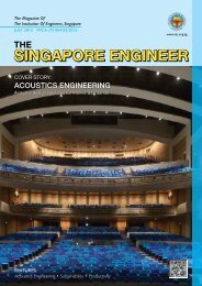
COVER STORY:<br />
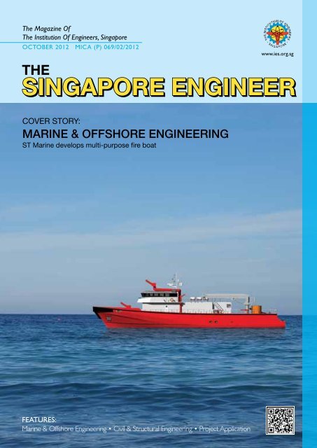
MARINE & OFFSHORE ENGINEERING<br />
ST Marine develops multi-purpose fire boat<br />
FEATURES:<br />
Marine & Offshore Engineering • Civil & Structural Engineering • Project Application
CONTENTS<br />
FEATURES<br />
12 MARINE & OFFSHORE ENGINEERING: Cover Story:<br />
ST Marine develops multi-purpose fire boat<br />
The vessel can be deployed for fire-fighting as well as search and rescue work.<br />
14 MARINE & OFFSHORE ENGINEERING:<br />
Sembcorp Marine offers full spectrum of integrated solutions<br />
The company’s capabilities have enabled it to gain international recognition.<br />
16 MARINE & OFFSHORE ENGINEERING:<br />
Wide-ranging benefits offered by BIM software<br />
Building Information Modelling is proving to be valuable in the <strong>engineer</strong>ing of structures.<br />
18 MARINE & OFFSHORE ENGINEERING:<br />
Lloyd’s Register and A*STAR to jointly promote innovation<br />
in the energy and marine sectors<br />
The collaboration will drive R&D activities and the development of technical solutions.<br />
19 MARINE & OFFSHORE ENGINEERING:<br />
Heave and VIM suppressed ‘HVS’ semi-submersible design<br />
for Southeast Asian environments<br />
Concepts for building oil platforms appropriate for the conditions in this<br />
region are presented.<br />
26 CIVIL & STRUCTURAL ENGINEERING:<br />
ITE College Central<br />
The third regional campus and headquarters of the educational institution features<br />
innovative and yet cost-effective design solutions.<br />
32 PROJECT APPLICATION:<br />
Floating on glass<br />
Important contributions were made in the installation of architectural finishes in the<br />
museum that houses the restored Cutty Sark clipper ship.<br />
36 PROJECT APPLICATION:<br />
Two Liebherr Flat-Top cranes building 85-storey skyscraper<br />
in Mumbai<br />
The machines are working in an unusual configuration to suit the project.<br />
37 PROJECT APPLICATION:<br />
Grove cranes building US$ 800 million plant in the Philippines<br />
The complicated project demands high safety standards and on-time completion.<br />
REGULAR SECTIONS<br />
02 IES UPDATE<br />
38 PRODUCTS & SOLUTIONS<br />
39 EVENTS<br />
42 NEWS<br />
Chief Editor<br />
T Bhaskaran<br />
t_b_n8@yahoo.com<br />
Director, Marketing<br />
Roland Ang<br />
roland@iesnet.org.sg<br />
Marketing & Publications Executive<br />
Jeremy Chia<br />
jeremy@iesnet.org.sg<br />
CEO<br />
Angie Ng<br />
angie@iesnet.org.sg<br />
Publications Manager<br />
Desmond Teo<br />
desmond@iesnet.org.sg<br />
Published by<br />
The Institution Of Engineers, Singapore<br />
70 Bukit Tinggi Road<br />
Singapore 289758<br />
Tel: 6469 5000 Fax: 6467 1108<br />
Cover designed by Irin Kuah<br />
Image of boat by ST Marine<br />
The Singapore Engineer is published<br />
monthly by The Institution of Engineers,<br />
Singapore (IES). The publication is<br />
distributed free-of-charge to IES members<br />
and affiliates. Views expressed in this<br />
publication do not necessarily reflect those<br />
of the Editor or IES. All rights reserved. No<br />
part of this magazine shall be reproduced,<br />
mechanically or electronically, without the<br />
prior consent of IES. Whilst every care is<br />
taken to ensure accuracy of the content<br />
at press time, IES will not be liable for any<br />
discrepancies. Unsolicited contributions<br />
are welcome but their inclusion in the<br />
magazine is at the discretion of the Editor.<br />
Design & layout by 2EZ Asia Pte Ltd<br />
Printed by Print & Print Pte Ltd.<br />
October 2012 THE SINGAPORE ENGINEER<br />
01
IES UPDATE<br />
Message from the President<br />
The marine & offshore sector plays an important role<br />
in the economic development of the world. Most of the<br />
trade across the world is facilitated by ships. And to meet<br />
the increasing demand for oil and gas, due to the rapid<br />
progress of countries and rising living standards, drilling<br />
operations are being conducted deeper into the seabed.<br />
In Singapore, too, the marine & offshore industries<br />
contribute substantially to the country’s economic<br />
growth. The country has become a world leader in ship<br />
repair and ship conversion, as well as in the construction<br />
of jack-up rigs and the conversion of tankers to FPSO (Floating Production Storage and<br />
Offloading) units. It is also involved in the construction of specialised vessels.<br />
Safety, security and environmental performance are major challenges in the marine &<br />
offshore sector. Accidents and incidents have been widely publicised - from the sinking of the<br />
Titanic exactly 100 years ago, to the BP oil spill in 2010 and the partial sinking of the cruise<br />
ship Costa Concordia in January this year as well as the several instances of piracy on the<br />
high seas.<br />
Under the leadership of the International Maritime Organization, and with the participation<br />
of all the stakeholders, measures are being taken to address these issues.<br />
In the area of environmental performance, for example, new regulations are expected to<br />
come into effect at the beginning of next year, that will require new ships to be designed such<br />
that they are more energy-efficient.<br />
On its part, the Maritime and Port Authority of Singapore is investing up to S$ 100 million,<br />
over five years, in the Maritime Singapore Green Initiative which seeks to promote clean and<br />
green shipping.<br />
Meanwhile, IES celebrated its 46th anniversary on 28 September 2012, at its Annual Dinner,<br />
held at Resorts World Sentosa. Deputy Prime Minister (DPM) Teo Chee Hean, Coordinating<br />
Minister for National Security and Minister for Home Affairs was the Guest-of-Honour.<br />
At the dinner, DPM Teo announced the launch of the IES Aerospace Engineering Chapter to<br />
support and strengthen Singapore’s position as the regional aerospace hub. The chapter will<br />
raise the profile of local aerospace <strong>engineer</strong>s and help them achieve higher standing globally,<br />
as well as encourage students to aspire to become aerospace <strong>engineer</strong>s. This new chapter<br />
will also develop critical mass to support professional development upgrading programmes.<br />
From 7 to 13 September 2013, IES will be hosting the inaugural World Engineers’ Summit<br />
(WES) which will be held in conjunction with the World Federation of Engineering<br />
Organizations (WFEO) General Assembly 2013. Addressing the theme ‘Innovative and<br />
Sustainable Solutions to Climate Change’, WES is expected to attract more than 2000<br />
delegates including <strong>engineer</strong>s from multiple disciplines, financiers, property developers, urban<br />
planning specialists, legal advisors, energy specialists, researchers and others.<br />
Co-located with WES will be Build Eco Xpo Asia 2013 (BEX Asia 2013), an exhibition on<br />
sustainable solutions for the building sector.<br />
The events will be held at the Sands Expo and Convention Center, Marina Bay Sands,<br />
Singapore.<br />
Prof Chou Siaw Kiang<br />
President<br />
The Institution of Engineers, Singapore (IES)<br />
IES COUNCIL MEMBERS<br />
2012/2013<br />
President<br />
Prof Chou Siaw Kiang<br />
Vice Presidents<br />
Er. Chong Kee Sen<br />
Er. Edwin Khew<br />
Dr Kwok Wai Onn, Richard<br />
Mr Neo Kok Beng<br />
Er. Ong Geok Soo<br />
Er. Ong See Ho<br />
Honorary Secretary<br />
Dr Boh Jaw Woei<br />
Honorary Treasurer<br />
Mr Kang Choon Seng<br />
Assistant Honorary Secretary<br />
Er. Koh Beng Thong<br />
Assistant Honorary Treasurer<br />
Er. Seow Kang Seng<br />
Immediate Past President<br />
Er. Ho Siong Hin<br />
Past Presidents<br />
Er. Dr Lee Bee Wah<br />
Er. Tan Seng Chuan<br />
Honorary Council Member<br />
Er. Ong Ser Huan<br />
Council Members<br />
Prof Chau Fook Siong<br />
Er. Dr Chew Soon Hoe<br />
Ms Fam Meiling<br />
Er. Dr Ho Kwong Meng<br />
Dr Ho Teck Tuak<br />
Mr Lee Kwok Weng<br />
Mr Lim Horng Leong<br />
Mr Ng Sing Chan<br />
Mr Oh Boon Chye, Jason<br />
Er. Tan Shu Min, Emily<br />
Mr Tan Boon Leng, Mark<br />
Er. Toh Siaw Hui, Joseph<br />
Er. Wong Fee Min, Alfred<br />
Dr Zhou Yi<br />
02 THE SINGAPORE ENGINEER October 2012
October 2012 THE SINGAPORE ENGINEER<br />
03
IES UPDATE<br />
IES celebrates 46th anniversary with<br />
new initiatives<br />
IES celebrated its 46th anniversary on 28 September 2012 at<br />
the IES Annual Dinner held at the Compass West Ballroom,<br />
Resorts World Sentosa, with some of the industry’s most eminent<br />
<strong>engineer</strong>s and IES members in attendance. Deputy Prime Minister<br />
(DPM) Teo Chee Hean, Coordinating Minister for National<br />
Security and Minister for Home Affairs, was the Guest-of-Honour.<br />
At the dinner, DPM Teo announced the launch of the IES<br />
Aerospace Engineering Chapter by IES to support and<br />
strengthen Singapore’s position as the regional aerospace hub.<br />
The chapter will raise the profile of local aerospace <strong>engineer</strong>s<br />
and help them achieve higher standing globally, and encourage<br />
students to aspire to become aerospace <strong>engineer</strong>s in the future.<br />
This new Chapter will also develop critical mass to support<br />
professional development upgrading programmes.<br />
In addition, DPM Teo announced the launch of the IES Technology<br />
Entrepreneurship Ecosystem. This will come complete with<br />
technology sources, funding, mentorship, incubation facilities<br />
and networking opportunities, to encourage more <strong>engineer</strong>s to<br />
start technology enterprises, building upon their expertise and<br />
innovations.<br />
“IES has marked the past 46 years with significant achievements<br />
that have contributed to the advancement of <strong>engineer</strong>ing in<br />
Singapore. As we celebrate yet another anniversary, we are not<br />
resting on our laurels but have introduced initiatives that will<br />
create major positive impact to the <strong>engineer</strong>ing community.<br />
We are confident that the new IES Aerospace Engineering<br />
Chapter and the Technology Entrepreneurship Ecosystem are<br />
highly relevant and beneficial to both the industry and the<br />
individual, and will buttress the ability of <strong>engineer</strong>s to transform<br />
our economy and our lives,” said Prof Chou Siaw Kiang,<br />
President of IES.<br />
The launch of the ‘Certified Engineer’ programme was also<br />
announced, targeting <strong>engineer</strong>s who are in fields that do not<br />
warrant a need for them to be registered as Professional Engineers.<br />
“The ‘Certified Engineer’ title will be a quality mark earned by<br />
<strong>engineer</strong>s of diverse <strong>engineer</strong>ing disciplines and will be an official<br />
endorsement of their experience, expertise and practising<br />
competence, and an accreditation of the individual’s professional<br />
standing. IES hopes to work with all <strong>engineer</strong>s to establish this<br />
new title as society’s recognition of an <strong>engineer</strong>’s professional<br />
expertise and experience across the sectors of our economy,”<br />
said Prof Chou.<br />
Prof Chou also shared with the dinner attendees that IES will<br />
be hosting the World Federation of Engineering Organisations<br />
(WFEO) General Assembly in 2013. In conjunction with the<br />
General Assembly, IES will be organising the inaugural World<br />
Engineers’ Summit (WES) 2013 which will be held in Singapore<br />
every two years.<br />
Focusing on the theme ‘Innovative and Sustainable Solutions to<br />
Climate Change’, WES 2013 will gather more than 2000 <strong>engineer</strong>s<br />
globally from multiple disciplines of <strong>engineer</strong>ing, financiers, policy<br />
makers, small and medium enterprises, legal advisors, scientists,<br />
researchers, MNCs and institutions to congregate, discuss and<br />
exchange ideas on climate change issues.<br />
A key highlight of the IES Annual Dinner was the presentation<br />
of certificates to the 74 elected Fellows of the Singapore<br />
Academy of Engineering (SAEng) by DPM Teo, a patron of the<br />
group. The presentation highlighted the thought leadership roles<br />
that this esteemed group will play in Singapore’s quest to meet<br />
the challenges of the new millennium and to build a vibrant<br />
<strong>engineer</strong>ing community in Singapore by leveraging on the rich<br />
experience and expertise of the group’s members.<br />
In line with its objectives to encourage brilliant young minds to<br />
pursue <strong>engineer</strong>ing as a lifelong career, IES also presented the<br />
IES Gold Medal to 17 top <strong>engineer</strong>ing students who are ranked<br />
first in general proficiency throughout their course of study from<br />
the National University of Singapore and Nanyang Technological<br />
University (NTU); and the IES-Yayasan Mendaki Scholarship.<br />
IES Gold Medal Recipients:<br />
National University of Singapore (NUS)<br />
Li Minghui Samuel (Bachelor of Engineering - Electrical Engineering)<br />
Moh Weixian, Wilson (Bachelor of Technology - Chemical Engineering)<br />
Wang Yingting (Bachelor of Engineering - Bio<strong>engineer</strong>ing)<br />
Anne Marie Tan Zhao Hui (Bachelor of Engineering - Materials<br />
Science & Engineering)<br />
Chee Nan Wei (Xu Nanwei), Victor (Bachelor of Technology -<br />
Electronics Engineering)<br />
Gan Jie (Bachelor of Engineering - Environmental Engineering)<br />
Hu Xiang (Bachelor of Engineering - Industrial & System Engineering)<br />
Huang Xiasha (Bachelor of Engineering - Civil Engineering)<br />
Li Jiashu (Bachelor of Engineering - Computer Engineering)<br />
Ooi Hee Siong (Bachelor of Technology - Mechanical Engineering)<br />
Pang Tao (Bachelor of Engineering - Mechanical Engineering)<br />
Tan Hui Ling (Bachelor of Engineering - Chemical Engineering)<br />
Wong Tse Jian (Bachelor of Engineering - EngineerIng Science)<br />
Nanyang Technological University (NTU)<br />
Jong Ming Chuan (Civil & Environmental Engineering)<br />
Lu Xiaowei (Electrical & Electronic Engineering)<br />
Ng Lee Ping (Mechanical & Aerospace Engineering)<br />
Neetika Bansal (Computer Engineering)<br />
IES-Yayasan Mendaki Scholarship Recipients:<br />
Nadia Bte Sulaiman (Diploma in Green Building and Sustainability,<br />
Temasek Polytechnic)<br />
Abdul Hanif Bin Zaini (Bachelor of Aerospace Engineering, NTU)<br />
04 THE SINGAPORE ENGINEER October 2012
October 2012 THE SINGAPORE ENGINEER<br />
05
IES UPDATE<br />
Pictures from IES 46th Annual Dinner<br />
06 THE SINGAPORE ENGINEER October 2012
IES UPDATE<br />
October 2012 THE SINGAPORE ENGINEER<br />
07
IES UPDATE<br />
Er. Ong See Ho receives NUS Distinguished<br />
Engineering Alumni Award<br />
Er. Ong and attendees of the NUS Engineering Alumni Gala Dinner representing IES take a group photo on stage.<br />
IES Vice President, Er. Ong See Ho, has been awarded the<br />
prestigious NUS Distinguished Engineering Alumni Award<br />
for his outstanding contributions to the profession and the<br />
<strong>engineer</strong>ing community.<br />
Er. Ong has been an IES member since 1978 and became<br />
an IES Fellow in 2003. He has been a Council member since<br />
2007. He is currently the Deputy CEO (Building Control)<br />
of the Building and Construction Authority (BCA) and<br />
the Commissioner of Building Control. He is also a Board<br />
member of the Professional Engineers Board (PEB) and the<br />
Board of Architects Singapore.<br />
The Distinguished Engineering Alumni Awards were<br />
instituted in 1989 and conferred on <strong>engineer</strong>ing alumni who<br />
have distinguished themselves nationally or internationally by<br />
their excellent and sustained contributions and achievements<br />
in public and community service, entrepreneurship, or in a<br />
profession or scholarly field.<br />
Our congratulations to Er. Ong for this distinguished honour!<br />
Er. Ong (left) receives the NUS Distinguished Engineering Alumni Award from<br />
Professor Chan Eng Soon, Dean, Faculty of Engineering, NUS.<br />
08 THE SINGAPORE ENGINEER October 2012
October 2012 THE SINGAPORE ENGINEER<br />
09
IES UPDATE<br />
Inaugural World Engineers’ Summit<br />
(WES 2013) to take place in Singapore<br />
The Institution of Engineers, Singapore (IES) announced that<br />
Singapore will host the inaugural World Engineers’ Summit<br />
(WES) from 7 to 13 September 2013, in conjunction with<br />
the World Federation of Engineering Organisations (WFEO)<br />
General Assembly 2013, at Sands Expo and Convention Centre,<br />
Marina Bay Sands, with IES as the organiser.<br />
Focusing on the theme ‘Innovative and Sustainable Solutions to<br />
Climate Change’, WES 2013 will gather more than 2000 <strong>engineer</strong>s<br />
from multiple disciplines, financiers, property developers, urban<br />
planning specialists, legal advisors, energy specialists, researchers<br />
and institutions to congregate and exchange ideas on climate<br />
change issues threatening the earth.<br />
An integral segment of WES 2013 will be the Sustainability<br />
Leadership Forum, scheduled to take place on 11 September<br />
2013. This Forum will provide participants with a valuable<br />
opportunity to listen to the perceptions and observations of a<br />
panel of thought leaders on a range of sustainability and climate<br />
change issues. The event will feature prominent international<br />
sustainability experts as speakers.<br />
“In the face of increasingly pressing issues resulting from climate<br />
change, the world needs viable and sustainable solutions<br />
to address the fall-out. Engineers are well-positioned to be<br />
thought leaders and the deliverers of insightful, sustainable and<br />
technology-led solutions to benefit mankind. As the national<br />
society of <strong>engineer</strong>s, IES is creating WES 2013 as the platform<br />
to gather expert viewpoints and to facilitate the surfacing of<br />
solutions,” said Er. Tan Seng Chuan, Chairman, WES 2013 Steering<br />
Committee, and Vice President, WFEO.<br />
Kick-off Event: “National Climate Change Strategy<br />
2012” Talk<br />
To create focus on WES 2013, IES presented the first lead-up<br />
event on 7 September 2012, at the Matrix Auditorium, Biopolis,<br />
from 6 pm to 9 pm. The speaker, Mr Yuen Sai Kuan, Director,<br />
3P Network, National Climate Change Secretariat (NCCS),<br />
explained the key elements of the National Climate Change<br />
Strategy 2012 (NCCS-2012) unveiled by Deputy Prime Minister<br />
Teo Chee Hean in June 2012. The NCCS-2012 will outline<br />
Singapore’s strategy and plans to address climate change and<br />
will be entitled ‘Climate Change and Singapore: Challenges.<br />
Opportunities. Partnerships.’<br />
“The NCCS-2012 describes how Singapore is addressing<br />
climate change by reducing carbon emissions, building<br />
capabilities to adapt to the impact of climate change, harnessing<br />
green growth opportunities and forging partnerships on<br />
climate change action. To tackle the challenges of climate<br />
change effectively, we require support and participation from<br />
all stakeholders. In this regard, NCCS is pleased to work with<br />
the IES through the WES 2013 and related forums to engage<br />
the <strong>engineer</strong>ing community,” said Mr Yuen.<br />
10 THE SINGAPORE ENGINEER October 2012<br />
Co-locating with WES 2013 is Build Eco Xpo (BEX) Asia 2013,<br />
an exhibition that addresses sustainable and green solutions for<br />
the building sector. Together, the two events aim to encourage<br />
discussion on environmentally friendly solutions.<br />
Information on WES 2013 is available at www.WES2013.org<br />
IES President, Prof Chou Siaw Kiang, makes the announcement on WES2013.<br />
Er. Tan Seng Chuan talks about innovative and sustainable solutions to<br />
climate change.
October 2012 THE SINGAPORE ENGINEER<br />
11
COVER STORY<br />
ST Marine develops multi-purpose fire boat<br />
by Dr Nigel Koh, Manager, Initial Design Group, ST Marine Ltd<br />
Customers will be able to increase their capabilities in fire-fighting as well as search and<br />
rescue operations.<br />
As reported by the US Fire Administration in its special technical<br />
report (2003) titled ‘Fireboats: Then and Now’, many fire<br />
departments are transitioning from larger traditional fireboats to<br />
smaller, faster and more versatile craft designed and configured<br />
for multiple operational roles.<br />
In the report, the US Fire Administration clearly defines three<br />
basic functions of the multi-purpose fireboats, as follows:<br />
• They serve as vehicles for conducting rescue operations and<br />
transporting personnel and equipment to and from incidents<br />
that are inaccessible from shore for land-based fire-fighters.<br />
• They provide a stable platform for conducting and supporting<br />
marine fire-fighting operations. Fireboats serve as forward<br />
operational command posts for marine and some land-based<br />
fire operations, rescue and recovery missions, and marine<br />
environmental emergencies.<br />
• They play a critical role in the supply of water for many kinds<br />
of land-based fire operations and during natural and manmade<br />
disasters.<br />
In early 2011, ST Marine began in-house development of multipurpose<br />
fireboats to provide potential customers with solutions<br />
to enhance their fire-fighting capabilities. Primarily, there are<br />
three areas - fire-fighting (Fi-Fi) for merchant and passenger<br />
vessels, fire-fighting in coastal regions and refineries, and search<br />
and rescue missions in case of marine disasters and oil spills.<br />
ST Marine’s fireboat is designed to measure 42 m in length,<br />
with a 10 m beam and a 3 m draft. It has a semi-displacement<br />
hard chine steel monohull and aluminium superstructure.<br />
With a response speed of over 18 knots, achieved through a<br />
quadruple-screw, controllable pitch propeller system, it will be<br />
driven by four MTU 12 V 4000 M70 main engines, each rated<br />
1671 kW at 2,000 rpm. The main engines are also directly<br />
coupled to drive the four main fire pumps through their Power-<br />
Take-Offs (PTOs) on the front end. Station-keeping of the vessel<br />
The fireboat has a semi-displacement hard chine steel monohull and<br />
aluminium superstructure.<br />
The multi-purpose fireboat, with Fi-Fi III capability, has been developed in-house by ST Marine.<br />
12 THE SINGAPORE ENGINEER October 2012
COVER STORY<br />
during fire-fighting is enhanced by the incorporation of electric<br />
motors which are powered by auxiliary generators, driving the<br />
controllable pitch propellers and a bow thruster.<br />
The designed fire-fighting equipment meets the Fi-Fi III<br />
requirement with the vessel built for continuous fighting of<br />
large fires from a safe distance and for the cooling of structures<br />
on fire. The total pumping capacity is in excess of 9600 m 3 /hr<br />
and, with three fixed water monitors in use, the fireboat has<br />
sufficient fuel oil for continuous fire fighting operations for a at<br />
least 96 hours. The capacity of each monitor is 3200 m 3 /hr with<br />
the length of throw at 180 m and height of throw at 110 m.<br />
The vessel is also protected by a permanently installed waterspraying<br />
system.<br />
The wheelhouse is specially designed with 360º all-round<br />
visibility and a skylight fitted on top so that Fi-Fi in action can<br />
be closely monitored from within the wheelhouse. The vessel<br />
will be equipped with modern radio communication systems<br />
and visual systems. The centralised operation of the fireboat,<br />
is designed to be equipped with visual aids, such as remote<br />
operated cameras to control and focus the water and foam to<br />
extinguish any raging fire.<br />
A fan room with high performance fans and a special air filtration<br />
system is fitted within the vessel, to enable it to respond to<br />
any CBRN (Chemical, Biological, Radiological, and Nuclear)<br />
accident. The fireboat is also equipped with first aid facilities and<br />
decontamination capabilities including a multi-head shower, to<br />
provide first aid to injured personnel and decontaminate crew/<br />
casualties, respectively. Fully equipped as a marine ambulance to<br />
provide a primary treatment area for any casualties, the triage<br />
room includes a transport room with comfortable seating<br />
area for treated casualties. Finally, the fire equipment room is<br />
outfitted to store hoses, fittings and rescue equipment which<br />
can be accessed through a roller shutter door.<br />
Outfitted to house up to 10 crew, 50 fire-fighters and 50<br />
evacuees, the crew accommodation consists of a resting area,<br />
pantry, mess room and washroom, thoughtfully incorporated into<br />
the design, to cope with the likelihood of extended operations.<br />
On the fireboat is a crane fitted with a telescoping ladder for<br />
facilitating a high-level water stream, personnel transfer, and<br />
embarkation and disembarkation for different ship types. The<br />
fast rescue boat can be deployed rapidly for Fi-Fi and rescue<br />
missions in restricted and shallow waters. Furthermore, the<br />
vessel has provided for a fire hydrant manifold arranged on the<br />
port side and another on the starboard side, each with eight<br />
hose connections to supply water to shore. To mitigate fires and<br />
environmental emergencies, such as oil spills and the release<br />
of other hazardous substances into ports and waterways, the<br />
vessel is also designed to be equipped with containment booms,<br />
foam, skimmers, absorbents, and other equipment.<br />
All images by ST Marine.<br />
The fast rescue boat can be rapidly deployed for Fi-Fi and rescue missions in<br />
restricted and shallow waters.<br />
Arrangement of the fire-fighting and life-saving equipment on deck.<br />
October 2012 THE SINGAPORE ENGINEER<br />
13
MARINE & OFFSHORE ENGINEERING<br />
Sembcorp Marine offers full spectrum of<br />
integrated solutions<br />
The company specialises in ship repair, shipbuilding, ship conversion, rig building and<br />
offshore <strong>engineer</strong>ing & construction.<br />
Internationally renowned for its rig building and offshore<br />
conversion expertise, Sembcorp Marine has established strong<br />
capabilities in the design of rigs and drillships as well as a proven<br />
track record in the fast-track turnkey construction of semisubmersibles<br />
and jack-ups, the <strong>engineer</strong>ing and construction of<br />
offshore platforms, and the conversion of floating production<br />
and storage facilities.<br />
Offering a complete suite of turnkey services to serve the offshore<br />
oil and gas industry, the company’s specialised capabilities range<br />
from the <strong>engineer</strong>ing, procurement and construction of offshore<br />
production platforms and floating production systems, to the<br />
fabrication, integration, pre-commissioning, as well as offshore<br />
hook-up and commissioning of topside process modules and<br />
production modules for fixed platforms and mega floating<br />
production, storage and offloading units (FPSOs).<br />
Sembcorp Marine is also recognised as an industry leader in ship<br />
repair and a niche player in the design and newbuilding of a wide<br />
variety of vessels, from 2,600 TEU containerships, bulk carriers<br />
and cable-laying vessels to ice-breaking tugs.<br />
With operations in Singapore and overseas, the company has<br />
one of the largest marine and offshore <strong>engineer</strong>ing facilities in the<br />
region. By leveraging on complementary facilities and capabilities,<br />
the company’s shipyards work in synergy to provide customers<br />
a full range of integrated, customised solutions - ranging from<br />
conceptualisation and design, <strong>engineer</strong>ing, procurement and<br />
construction, through to commissioning and delivery.<br />
CORE CAPABILITIES<br />
Ship repair<br />
Sembcorp Marine has expertise to provide a full range of ship<br />
repair services to tankers of varying sizes ranging from midsized<br />
tankers to Very Large Crude Carriers (VLCCs) and Ultra<br />
Large Crude Carriers (ULCCs). The group also repairs a wide<br />
variety of vessels including chemical tankers, container vessels,<br />
passenger ships, gas carriers (LNG and LPG), dredgers, bulk<br />
carriers, derrick barges and navy vessels.<br />
Shipbuilding<br />
The group also designs and constructs product tankers of about<br />
11,500 dwt and 1,078 TEU to 2,600 TEU container carriers.<br />
Other projects include building dynamic positioning heavy lift<br />
pipelaying vessels, fallpipe rock dumping vessels, tankers of about<br />
90,000 dwt, ocean-going tugs, ice-class chemical tankers, multipurpose<br />
cargo vessels, ro-ro vessels, bulk carriers and cable<br />
laying and repair vessels.<br />
Ship and offshore conversions<br />
Offshore conversions<br />
Sembcorp Marine’s offshore conversion track record includes<br />
the conversion of floating production storage and offloading<br />
(FPSO) vessels, floating storage and offloading (FSO) units,<br />
floating drilling production storage and offloading (FDPSO)<br />
vessels, floating storage and regasification units (FSRU), as<br />
well as the conversion of dynamic positioning pipe-laying and<br />
construction barges.<br />
Chevron Shipping Company’s Capricorn Voyager sails away in February 2012, after completing drydocking repairs at Jurong Shipyard, as part of the strategic alliance<br />
between the shipping company and the yard. Image by Sembcorp Marine.<br />
14 THE SINGAPORE ENGINEER October 2012
MARINE & OFFSHORE ENGINEERING<br />
Specialised ship conversions<br />
The company’s specialised ship conversion capabilities include<br />
the conversion of tankers to lightering vessels, cargo vessels to<br />
livestock carriers, cargo vessels to container ships, power barge<br />
conversions and the jumboisation and dejumboisation of vessels.<br />
Offshore repairs<br />
The group has specialised expertise in servicing offshore<br />
platforms, including the repairing and upgrading of jack-up<br />
drilling rigs, and the upgrading of semi-submersible rigs for deepwater<br />
drilling.<br />
Rigbuilding<br />
A global leader in rig building, Sembcorp Marine has proven<br />
capabilities in the proprietary design and building of deep<br />
drilling offshore jack-up rigs and in the fast-track construction<br />
of highly sophisticated dynamic positioning semi-submersible<br />
and production semi-submersible rigs for the offshore oil and<br />
gas industry. Other offshore newbuilding projects undertaken<br />
by the company include the construction of heavy-lift jack-up<br />
barges, work-over rigs and offshore platforms.<br />
Offshore <strong>engineer</strong>ing and construction<br />
Sembcorp Marine offers total solutions in the <strong>engineer</strong>ing,<br />
procurement, construction, transportation, installation, offshore<br />
hook-up and commissioning of offshore production platforms<br />
and floating production facilities for the oil and gas industries.<br />
The group’s specialised capabilities also extend to the fabrication,<br />
installation, integration and commissioning of topside production<br />
modules for fixed platforms and mega FPSOs.<br />
GLOBAL NETWORK<br />
Sembcorp Marine’s Singapore hub operations consist of Jurong<br />
Shipyard, Sembawang Shipyard, SMOE, PPL Shipyard and Jurong<br />
SML, as well as its new integrated Tuas Yard facility, supported<br />
by Indonesian yards PT Karimun Sembawang Shipyard and PT<br />
SMOE Indonesia.<br />
The group’s global network includes overseas shipyards<br />
Estaleiro Jurong Aracruz in Brazil, Sembmarine Kakinada in India,<br />
Sembcorp-Sabine Shipyard in the US, Sembmarine SLP in the<br />
UK and strategic operations in China.<br />
Integrated new yard facility<br />
Sembcorp Marine’s integrated new yard facility at Tuas View<br />
Extension will further reinforce the company’s competitive edge,<br />
enabling it to respond effectively to customers’ requirements<br />
and future challenges.<br />
The new yard facility is designed to maximise operational<br />
synergy, production efficiency and critical mass with optimised<br />
docking and berthing facilities, an improved dock and quay ratio,<br />
a centralised work-efficient layout, and integrated facilities.<br />
The 206-hectare new yard facility will be built in three phases.<br />
Phase I, which spans 73.3 hectares, will focus on ship repair and<br />
conversion activities and is scheduled to be completed in the<br />
second half of 2013. Phase I will feature four VLCC drydocks<br />
totalling 1,550,000 dwt, a 3,408 m quay, as well as workshops for<br />
hull and fitting works, a blasting and painting chamber, warehouse<br />
and craneage facilities. It will also house a Health, Safety and<br />
Environment (HSE) Centre along with medical clinic facilities, a<br />
training centre, owners’ offices and a multi-storey dormitory for<br />
the workforce.<br />
The new yard facility will be well-equipped to serve a wide<br />
range of vessels including VLCCs, new generations of mega<br />
containerships, LNG carriers and passenger ships, as well as meet<br />
new regulatory requirements and environmental standards.<br />
TECHNOLOGIES<br />
Research and Development<br />
Sembcorp Marine continues to strengthen its technological<br />
and competitive capabilities to stay at the forefront of industry<br />
developments and advancements.<br />
Through sustained investments in research and development,<br />
the group has developed proprietary capabilities, solutions<br />
and designs, such as the innovative ‘Load-out & Mating’ and<br />
‘Transverse Skidding’ fast-track semi-submersible construction<br />
techniques as well as the Jurong Espadon drillship design and<br />
the Pacific Class jack-up series.<br />
These innovations and intellectual assets have enabled Sembcorp<br />
Marine to further enhance its competitive edge and reinforce its<br />
leading position in the marine and offshore industry.<br />
In June 2012, Jurong Shipyard successfully delivered Atwood Condor, an ultra-deepwater semi-submersible with dynamic positioning capability, built by the yard for Atwood<br />
Oceanics. Image by Sembcorp Marine.<br />
October 2012 THE SINGAPORE ENGINEER<br />
15
MARINE & OFFSHORE ENGINEERING<br />
Wide-ranging benefits offered by BIM software<br />
Mr Michael Hodgson, Technical Manager, Steel Segment, Tekla Oyj explains how the company’s<br />
products assist <strong>engineer</strong>s, detailers, fabricators, contractors and others in the <strong>engineer</strong>ing,<br />
fabrication and erection of structures.<br />
Question: Could you provide some<br />
information on Tekla’s products<br />
for offshore <strong>engineer</strong>ing?<br />
Answer: We believe that Tekla<br />
provides the most advanced and<br />
integrated BIM (Building Information<br />
Modelling) software for offshore<br />
and EPC structures. Tekla software<br />
is used to manage the <strong>engineer</strong>ing,<br />
Mr Michael Hodgson<br />
detailing, fabrication and erection of all types of structures,<br />
including offshore platforms, topsides and jackets.<br />
Tekla Structures provides accurate, dynamic and data-rich 3D<br />
building information models that can be utilised by offshore<br />
contractors, structural <strong>engineer</strong>s, steel detailers and fabricators,<br />
amongst others. With this way of working, we help our customers<br />
and partners create new opportunities for themselves in the<br />
offshore construction industry.<br />
Key to the success of our customers’ projects is Tekla BIM<br />
software’s ability to centralise building information into the<br />
model, allowing for more collaborative and integrated project<br />
management, fabrication and delivery. This ultimately translates<br />
to increased productivity and elimination of waste, thus making<br />
offshore construction more sustainable and profitable.<br />
Q: What specific benefits do these products bring to <strong>engineer</strong>s,<br />
detailers, fabricators and others?<br />
A: Tekla BIM software is used by many fabricators, <strong>engineer</strong>ing<br />
consultants and oil & gas companies all over the world to model<br />
and prototype their offshore steel structures such as platforms,<br />
structural decks, jacket, main support frames, modules, flare<br />
boom, boat landing, helideck and piping supports, that are then<br />
constructed and used for processes like drilling and production.<br />
Tekla Structures users can work simultaneously on the same<br />
central offshore model, and then automatically generate<br />
<strong>engineer</strong>ing, fabrication and erection drawings and also reports<br />
from the model. Ultimately, Tekla Structures links to CNC<br />
machines for automated fabrication including plate, beam<br />
and complex pipe cutting processes. Creating schedules and<br />
fabrication planning are also done as the model is built within<br />
the software. Customisable marking of all parts (including<br />
welds) allows for unique, identical, or hybrid numbering systems<br />
which enable efficient traceability throughout fabrication and<br />
construction. Automated clash checking exposes conflicts<br />
from all disciplines already within the model and minimises<br />
costly errors through superior change management and<br />
revision control.<br />
Using TeklaBIMsight, the free design co-ordination software,<br />
our users can then share the Tekla 3D model with anyone<br />
else around the world who would like to fly around the<br />
structure and interrogate elements.<br />
16 THE SINGAPORE ENGINEER October 2012<br />
Tekla BIM offshore models are the window to reliable project<br />
information during the fabrication process.<br />
Q: Could you comment on the interoperability between Tekla<br />
software and other software used for the <strong>engineer</strong>ing of<br />
offshore structures?<br />
A: Through Tekla Open API, Tekla Structures links to all<br />
major offshore design software systems for fully integrated<br />
analysis and design workflow. Tekla BIM software can easily<br />
integrate with all offshore industry-standard plant modelling<br />
packages, such as Intergraph SmartPlant 3D, SmartMarine<br />
3D, PDS, Aveva PDMS and also analysis and design software<br />
like SFrame, Staad Pro, Midas, SAP2000 etc. Tekla structures<br />
can accept other 3D designs from all major 3D modelling<br />
software applications for final co-ordination purposes, thus<br />
facilitating fast and error-free design and detailing, and<br />
ultimately saving our customers time and money.<br />
Q: What are some of the projects where Tekla software has<br />
contributed significantly to successful outcomes?<br />
A: Since the late 1950s, Saipem’s Offshore division has built<br />
a global reputation as one of the true innovators in the field<br />
of offshore construction. In fact, Saipem has completed<br />
approximately 120 offshore construction projects within the last<br />
decade and the current potential of Saipem’s fabrication facilities<br />
exceeds an aggregate of 130,000 t per annum. The company has<br />
been using Tekla BIM to design its platforms since 2004, greatly<br />
benefitting from the availability of a single structural model<br />
from which they can extract project plans and detailing, lists of<br />
materials, weights and centres of gravity.<br />
Tekla BIM was key to completion of the Halfdan BB, an<br />
unmanned platform situated in the North Sea at a location<br />
where the depth reaches 50 m. The design of the deck structure<br />
was completed with Tekla Structures which enabled continuous<br />
monitoring of the weight of the structure and the position of the<br />
deck structure’s centre of gravity during the design phase. The<br />
ability of Tekla Structures to output 2D drawings when needed<br />
also simplified the certification process and development of<br />
workshop designs used on the construction site. Saipem believes<br />
that Tekla Structures will continue to boost the efficiency of its<br />
work processes as well as the quality of the results that can be<br />
derived from the model.<br />
Lamprell, a leader in the rig and topsides solutions market<br />
throughout the Gulf Region, has been using Tekla BIM software<br />
since 2007, and has seen savings of at least 25% to 30% in<br />
time, compared to its earlier way of working. The company’s<br />
main challenge was the lack of custom components as it had<br />
to model every part of the vessel. This was also made more<br />
difficult with the need for all weld preps on the drawings,<br />
which meant that it had to model each component. The unique<br />
features in Tekla Structures, such as the copying of bulkheads,<br />
frames, and manholes, without the need to model the details of
MARINE & OFFSHORE ENGINEERING<br />
Tekla software ensured the consistency of interfaces during modelling of the Lamprell Bassdrill Alpha barge.<br />
The unique features in Tekla Structures enabled Lamprell to deal with pipe<br />
profiles very accurately.<br />
bevels, contributed to the success of its projects. The software<br />
also enabled Lamprell to deal with pipe profiles very accurately.<br />
Lamprell is also involved in building topside modules for floating<br />
production, storage and offloading (FPSO) units which have<br />
numerous uses. They receive crude oil directly from underwater<br />
wellheads; separate oil, gas and water; inject gas into the field<br />
for artificial lift requirement; store stabilised crude oil; and<br />
offload it via hoses to export tankers periodically moored<br />
to the FPSO. Utilising Tekla BIM, Lamprell was able to design<br />
FPSO topside modules with a multi-point support system and<br />
Lamprell’s FPSO Topside Modules won in the Best Offshore project category at the<br />
Tekla Middle East model competition in 2010<br />
with appropriate restraints that minimised interaction with the<br />
vessel’s hull structure.<br />
With Tekla software, Lamprell found that it can handle larger<br />
and more complex projects compared to other 3D modelling<br />
solutions, and that it can be utilised from initial concept studies,<br />
including 4D visualisation, to the design of structures, safety<br />
systems and sustainability, and all the way from commissioning<br />
and modifications to eventual decommissioning.<br />
All the above images by Lamprell.<br />
October 2012 THE SINGAPORE ENGINEER<br />
17
MARINE & OFFSHORE ENGINEERING<br />
Lloyd’s Register and A*STAR to jointly promote<br />
innovation in the energy and marine sectors<br />
At the signing ceremony are, from left, Mr John Wishart, Lloyd’s Register’s Global Energy Director; Dr Raj Thampuran, Managing Director of A*STAR; Dr Claus Myllerup,<br />
Managing Director, Singapore Group Technology Centre, Lloyd’s Register; and Mr Lim Chuan Poh, Chairman, A*STAR.<br />
Leading classification society Lloyd’s Register has established a<br />
world-class Group Technology Centre (GTC) in Singapore to<br />
deliver innovation and solutions to the energy and maritime<br />
sectors. It has also reached an agreement with the Agency for<br />
Science, Technology and Research (A*STAR) to collaborate on<br />
R&D projects as a key part of the centre’s activities.<br />
The intent is to establish a Joint Lab facility with A*STAR’s<br />
Institute for High Performance Computing (IHPC) to co-develop<br />
applications and solutions in the marine and offshore sectors.<br />
This arrangement will promote R&D activities in modelling<br />
and simulation, and provide bespoke technical solutions for<br />
companies in these sectors.<br />
To encourage the development of technical expertise and young<br />
<strong>engineer</strong>s, PhD students will be trained at the GTC during the<br />
programme’s initial five-year period. These students will be<br />
working on R&D projects between the technology centre and<br />
Singapore’s institutes of higher learning such as the National<br />
University of Singapore and Nanyang Technological University.<br />
“Our investment in the new Lloyd’s Register Group Technology<br />
Centre in Singapore, coupled with the agreement with A*STAR,<br />
represents a shared vision to create a long-term centre of<br />
excellence for technology, innovation and research that will<br />
benefit Singapore, industry and society at large”, said Mr Richard<br />
Sadler, Chief Executive Officer of Lloyd’s Register.<br />
“It underlines our global commitment to understanding the<br />
sciences and technologies that help to ensure that people are<br />
safe, and that essential assets perform as required”, he added.<br />
“The collaboration between Lloyd’s Register and A*STAR<br />
demonstrates common interest to develop technologies to<br />
18 THE SINGAPORE ENGINEER October 2012<br />
boost developments for the energy and maritime sectors. This<br />
partnership marks an important milestone in driving innovation<br />
and technology solutions for these key sectors”, said Dr Raj<br />
Thampuran, Managing Director of A*STAR.<br />
“Exciting areas of research include modelling and simulation;<br />
designing floating offshore structures, deep sea drilling equipment<br />
and transportation, maritime safety and environment, and marine<br />
energy harvesting. This relationship will grow stronger over time<br />
and contribute significantly to the growth of these sectors. I am<br />
confident that outcomes from our research collaboration will<br />
be keenly watched by key industry players”, he added.<br />
‘Along with our Group Technology Centre at the University<br />
of Southampton in the UK, the Singapore GTC will serve as a<br />
cornerstone for our global research and development network,<br />
which currently includes 48 academic and technical institutions<br />
sponsored by The Lloyd’s Register Educational Trust”, Mr Sadler said.<br />
The capabilities and resources of the new centre will be scaled<br />
up over five years to work on projects mutually identified by<br />
Lloyd’s Register and A*STAR under the new research agreement.<br />
Investment in this new centre is expected to reach US$ 35<br />
million. By year five, up to 150 full-time <strong>engineer</strong>s, researchers<br />
and doctoral students will be jointly employed and working<br />
together with industry on projects of mutual interest.<br />
“This strategic initiative will further strengthen the technological<br />
readiness of our organisation”, said Mr John Wishart, Lloyd’s<br />
Register’s Global Energy Director.<br />
“It will help to ensure that our energy and marine clients receive<br />
innovative technical solutions to maintain their competitive edge<br />
and sustain their leadership positions going forward”, he added.
MARINE & OFFSHORE ENGINEERING<br />
Heave and VIM suppressed ‘HVS’ semi-submersible<br />
design for Southeast Asian environments<br />
by Qi Xu and Jim Ermon, Technip<br />
The new design for oil production platforms is said to offer significant benefits.<br />
Glossary of acronyms<br />
CFD - Computational Fluid Dynamics<br />
CG - Centre of Gravity<br />
DTA - Dry Tree Application<br />
DVA - Direct Vertical Access<br />
GM - Distance between CG and metacentre<br />
GoM - Gulf of Mexico<br />
RAO - Response Amplitude Operator<br />
SCR - Steel Catenary Riser<br />
TLP - Tension Leg Platform<br />
TTR - Top Tensioned Riser<br />
VIM - Vortex Induced Motion<br />
BACKGROUND<br />
In offshore oil & gas production, with the trend towards<br />
implementing deeper, larger, and more complex offshore<br />
development projects, and moving into regions requiring more<br />
flexibility, there is a greater need to meet both the technical and<br />
cost challenges associated with this new frontier.<br />
Although, over the last several years, deep-draft semisubmersible<br />
concepts have been developed in the Gulf of<br />
Mexico as wet-tree floating production systems, it is envisioned<br />
that the production semi solution will be used in other parts of<br />
the world, as well (most notably in Southeast Asia), to address<br />
these challenges.<br />
The wet-tree floater market has been growing, largely due to:<br />
• Reservoirs favouring non-directional wells which lead to<br />
subsea production<br />
• Increased water depth (making SCR design easier and TTR<br />
design more difficult)<br />
• Choices of mature floater concepts<br />
Current wet-tree floater concepts include semi-submersibles,<br />
Spars, TLPs and ship-shaped vessels with and without turrets.<br />
Of these choices, the semisubmersible has become a favourite,<br />
primarily because of the key advantage of quayside integration<br />
of the ever increasing size and weight of topsides, a large deck<br />
area, ability to support a large number of risers, and overall costeffectiveness.<br />
However, conventional semi-submersibles continue to face<br />
challenges in supporting SCRs, particularly large ones, and the<br />
associated strength and fatigue issues as a result of relatively<br />
high heave motion. This is particularly true for semis operating in<br />
harsh environments and relatively shallow water. Heave motion<br />
increases the loading on the SCR near the riser touchdown<br />
zone. In an effort to improve the heave motion, the draft of the<br />
semi-submersibles has been increased.<br />
Unfortunately, as a result of increasing the draft, another challenge<br />
has been introduced - high VIM as a result of wind, loop, and tidal<br />
currents. The high VIM of a deep draft semi-submersible is mainly<br />
due to the increased VIM excitation from the longer columns<br />
and reduced damping from the smaller pontoons, compared to<br />
conventional semis. An SCR’s fatigue life at the touchdown point<br />
can be greatly compromised by the high VIM. Other factors also<br />
come into play as a result of VIM. For instance, VIM can make it<br />
difficult to meet mooring fatigue design criteria.<br />
INTRODUCTION<br />
Though VIM has been experienced by shallow draft semisubmersibles<br />
in the presence of strong surface current, it never<br />
became a driving design issue. With increasing draft, however, it<br />
has now become a fatigue design issue for risers and mooring,<br />
with no simple solution.<br />
Technip has long been recognised for its quality and reliable<br />
hull designs, such as the Spar hull. Specifically developed as a<br />
riser-friendly floater, suitable for both dry-tree and wet-tree<br />
applications, the Spar is a proven concept with excellent motion<br />
performance. Earlier Spars were primarily used as dry-tree units,<br />
while the recent few Spars are wet-tree applications.<br />
However, in the coming years, in order to meet evolving technical<br />
challenges of deeper and more complex field developments<br />
and increasing market needs, Technip is expanding its existing<br />
floater product portfolio by introducing to the market a new<br />
semi-submersible design - the heave and VIM suppressed ‘HVS’<br />
semi-submersible.<br />
The HVS semi-submersible was developed at Technip as a wettree<br />
floater which achieves significantly improved heave motion<br />
and VIM performance through hull form optimisation while<br />
maintaining the simplicity of a conventional semi-submersible<br />
design. Future enhancements of this design will also include<br />
direct vertical access and dry tree applications.<br />
This article explores the design of the new HVS semisubmersible,<br />
points out its many features, quantifies its<br />
performance, explains why it responds accordingly, and<br />
highlights its many advantages and benefits.<br />
October 2012 THE SINGAPORE ENGINEER<br />
19
MARINE & OFFSHORE ENGINEERING<br />
THE ‘HVS’ DESIGN AND FEATURES<br />
The HVS semi-submersible design is based on a simple, elegant<br />
solution, through the use of blisters constructed with sharp<br />
corners attached to the base of the column, not extending to<br />
the waterline. This design effectively breaks the vortex shedding<br />
coherence along the column length and results in suppressed<br />
VIM performance.<br />
The HVS semi-submersible design presented herein has the<br />
following features:<br />
1. Pontoon width is reduced without compromising the<br />
structural strength.<br />
2. Column blisters are added to provide the buoyancy and stability<br />
needed at quayside and the mass needed for the heave natural<br />
period. The blisters also help to reduce the VIM response.<br />
3. Tall pontoon (height-to-width ratio > 1) for effective VIM damping.<br />
Figure 1 depicts the wetted surface area of the HVS semisubmersible<br />
design, contrasted against a conventional semisubmersible<br />
design shown in Figure 2. As mentioned above, the<br />
blisters at the base of the column is key in the design. These<br />
blisters effectively introduce more three-dimensionality in the<br />
flow around columns. The pontoon is also made higher than<br />
is conventional for more damping. Meanwhile, the pontoon<br />
width and blister size are so selected that the requirements for<br />
pontoon structural strength, buoyancy at quayside and heave<br />
natural period are all met.<br />
Figure 1: HVS design.<br />
The principal dimensions of this particular example are shown<br />
in Table 1. Due to the asymmetric arrangement of the blisters<br />
(relative to column centre-line), it is also expected that the<br />
synchronisation of vortex shedding between the columns will<br />
be reduced to some degree.<br />
For comparison purposes, a more conventional semi-submersible<br />
design with the same principal dimensions, shown in Table 1 and<br />
Figure 2, is selected as a reference case.<br />
Component Unit HVS Conventional<br />
Column Width m 20 20<br />
Corner Radius m 4 4<br />
Column Spacing m 73 73<br />
Draft m 41 41<br />
Freeboard m 20 20<br />
Deck Box Height m 9.5 9.5<br />
Pontoon Width m 9 16<br />
Pontoon Height m 12 10<br />
Blister Height m 18 N/A<br />
Blister Depth m 8 N/A<br />
Table 1: Principal dimensions.<br />
Heave motion<br />
The HVS design addresses the need to reduce the load on<br />
the pontoon in order to reduce heave. A smaller pontoon<br />
means smaller wave load, but the pontoon is needed in a semisubmersible<br />
design, and its size is governed by the following<br />
design drivers:<br />
1. A sufficiently long heave natural period.<br />
2. Sufficient buoyancy at shallow draft for quayside integration<br />
and wet tow.<br />
3. Structural rigidity.<br />
The HVS design shifts a part of the pontoon volume to the<br />
four corners of the platform in the form of blisters attached to<br />
the columns. This effectively reduces heave load on the platform<br />
because the wave force acting on the widely separated blisters<br />
will not reach maximum at the same time, due to the wave<br />
phasing. The force on the pontoons in this design is significantly<br />
reduced, compared to conventional designs, while the force on<br />
the columns remains almost unchanged.<br />
Figure 3 shows a comparison of the heave RAO at CG (head<br />
seas) between the HVS and conventional semi-submersible<br />
designs, both designed for the same payload. In the calculation<br />
of the RAOs, a linear damping suitable for the response level in<br />
a 100-year hurricane is applied.<br />
The HVS semi is found to reduce the heave response from<br />
35% - 50% (Table 2). The draft is 41 m in both designs, and both<br />
designs have approximately the same heave natural period.<br />
Figure 2: Conventional design.<br />
20 THE SINGAPORE ENGINEER October 2012
MARINE & OFFSHORE ENGINEERING<br />
Figure 3: Heave motion RAO comparison.<br />
Hs Tp Gamma Max Heave Amp (m)<br />
(m) (sec) Conv HVS Reduction<br />
5 10 1 0.49 0.25 50%<br />
9 12 2 1.50 0.81 46%<br />
14 14 2.6 2.98 1.94 35%<br />
Table 2: Comparison of heave response at CG (head sea).<br />
VIM response<br />
It is known that a semi-submersible with a relatively shallow draft<br />
(around 24 m) experiences little or no VIM. It is believed that<br />
the strong three-dimensionality of the flow around a shallow<br />
draft semi-submersible leads to small VIM excitation. However,<br />
with the increased draft, the VIM response becomes more and<br />
more significant. This phenomenon is understood to be caused<br />
by the enhanced coherence of the vortex shedding along the<br />
column length for deep draft designs. One of the possible ways<br />
to reduce VIM response is to bring the three-dimensionality to<br />
the deep draft design. The blisters in the HVS semi-submersible<br />
design serve this purpose.<br />
From qualitative, theoretical analysis, the following observations<br />
can be made:<br />
• VIM amplitude is proportional to exciting force and inversely<br />
proportional to pontoon drag force (pontoon CD & lateral<br />
projected area).<br />
• CD is increased by 30% ~ 40% due to the high and<br />
narrow pontoon.<br />
• Pontoon lateral area is increased by about 20%.<br />
• Forcing function is expected to be less due to the interrupted<br />
vortex shedding coherence along the column length.<br />
• Synchronisation between columns may be disrupted to<br />
some degree.<br />
With all the effects combined, it is expected that the VIM<br />
response will be reduced by 40% - 60% with the HVS semisubmersible<br />
design. However, such a conclusion based on<br />
qualitative, theoretical analysis alone is not sufficient. Therefore,<br />
the expected VIM response was verified by CFD and model<br />
tests. Initial pilot CFD analysis did prove that the VIM response is<br />
reduced by about 50% in the HVS design.<br />
VIM model test<br />
To confirm the performance of the HVS design, towing tank<br />
model tests were performed in December of 2010 at FORCE<br />
Technology’s testing facilities. Figure 5 depicts the HVS model<br />
being prepared for towing tests. The tests compared the HVS<br />
semi-submersible to a more conventional design with the<br />
same hull dimensions, and were used to verify the qualitatively<br />
analysed VIM response and CFD predictions.<br />
To better illustrate this point, Figure 4 shows a snapshot<br />
comparison of flow visualisation using CFD analysis. The white<br />
cloud at the base of the conventional semi column indicates a<br />
continuous vortex along the length of the column, whereas the<br />
HVS blister effectively breaks up this vortex shedding and VIM<br />
is greatly reduced. The vortex cloud behind the HVS pontoon<br />
also shows relatively more damping than the conventional case.<br />
Figure 5: HVS model test.<br />
Several different hull configurations were tested:<br />
Case Pontoon Pontoon Blister Blister Remarks<br />
ID Width Height Height Width<br />
1 9m 12m 18m 8m Base Case<br />
2 9m 12m 15m 9m Sensitivity<br />
3 9m 12m 12m 10.5m Sensitivity<br />
4 16m 10m N/A N/A Conventional<br />
Figure 4: Flow visualisation comparison.<br />
October 2012 THE SINGAPORE ENGINEER<br />
21
MARINE & OFFSHORE ENGINEERING<br />
Figure 6 shows the comparison of VIM response between the<br />
conventional and HVS semi-submersible designs for the heading<br />
of 45º. It can be seen that the VIM response is reduced by more<br />
than 50%.<br />
Figure 6: Comparison of VIM Response from VIM Model Test.<br />
In addition to the above model tests, wave basin model tests<br />
have been conducted at MARIN’s testing facility, and the results<br />
will be published.<br />
ADVANTAGES AND BENEFITS OF ‘HVS’<br />
The above results of the HVS design are striking: Heave response<br />
for 100-year hurricane at hull CG is reduced by 35% - 50%, and<br />
VIM is reduced by 50% for critical headings. Consequently, this<br />
translates into multiple advantages and benefits, most notably<br />
with regard to improved riser characteristics.<br />
However, the HVS design also has other operational and safety<br />
advantages, such as enhanced stability at quayside, improved<br />
ballasting system, and fabrication economies accompanied by a<br />
reduced risk profile for construction/operation activities.<br />
Improved riser/mooring characteristics<br />
As a result of the reduced heave motion, the riser bending stress<br />
at the touchdown point is significantly reduced. Riser minimum<br />
tension at the touchdown point is increased, and the possibility<br />
of riser buckling in extreme and survival conditions is decreased,<br />
or eliminated.<br />
The reduced VIM response increases the VIM induced fatigue<br />
life by almost an order of magnitude. The HVS semi design also<br />
has a lower VIM induced roll motion, which will translate into<br />
reduced fatigue of the riser stress joint at the hang-off location.<br />
Also, the mooring chain fatigue due to VIM, which can be dominating<br />
for a VIM-prone design, is even more significantly reduced.<br />
Current analysis is underway to quantify these advantages.<br />
However, an early indication can be referenced from a recent<br />
analysis of a 14” gas export riser, in which VIM fatigue life near<br />
the touchdown zone was improved by about five times.<br />
Fabrication economies/safety benefits<br />
In addition to the benefits of improved riser characteristics, the<br />
HVS semi introduces several fabrication economies and safety<br />
features. For instance, the increased quayside stability from the<br />
blisters makes the hull design less sensitive to topside weight<br />
increase, which tends to decouple the hull and topsides design,<br />
and enables a more robust project execution. By increasing<br />
the blisters, additional stability is obtained, without the need to<br />
change column spacing.<br />
This benefit would allow an added margin for weight contingency,<br />
often (if not always) required in construction projects in<br />
which initial designed topsides’ weight increases as the project<br />
progresses. Alternatively, the operators could use the increased<br />
stability to save 4%-5% in column spacing and gain marginal<br />
weight savings. And, the HVS topside to hull weight ratio of<br />
approximately 1.1 is still maintained, similar to an equivalent<br />
conventional semi design, with little or no penalty for the design<br />
improvement - a key cost advantage.<br />
The HVS semi is also equipped with a caisson-based ballasting<br />
system, eliminating the need for pump rooms and sea<br />
chests inside the lower hull (Figure 7). Each quadrant has its<br />
independent filling and discharging lines, thus eliminating the<br />
possibility of cross flooding, and resulting in a much safer system.<br />
The requirement for entry into the lower hull for maintenance<br />
and inspection of the ballasting system is minimised, improving<br />
the operational safety and cost.<br />
Figure 7: Caissons at each quadrant.<br />
Key features of the hull systems in this design include the following:<br />
• Each column, pontoon quadrant is independent; no crossconnection<br />
of ballast system between pontoons and quadrants.<br />
• Use of electric submersible pumps.<br />
• No sea chest, or sea chest valves.<br />
• Minimises chance of cross flooding between water ballast tanks.<br />
• Redundancy of ballast discharge pumps in each column.<br />
• No free flooding into ballast tanks; ballast water must be raised to<br />
top of column before entering a ballast tank (up & over).<br />
• Pump fill and discharge valves are located at manifold column<br />
top for ease of access.<br />
Finally, the HVS semi can be designed with a deck box<br />
(shown in the artistic rendering, Figure 8) similar to existing<br />
22 THE SINGAPORE ENGINEER October 2012
MARINE & OFFSHORE ENGINEERING<br />
semi-submersibles such as Thunder Horse and Atlantis, or<br />
an open truss type deck similar to Na Kika. A deck box has<br />
the benefits of additional stability reserve (a vital measure of<br />
last resort in offshore column flooding mishaps), minimises<br />
equipment damage from wave run-up during storms, and adds<br />
structural strength.<br />
Figure 8: HVS artistic rendering with deck box.<br />
CONCLUSION<br />
Compared with conventional semi-submersibles, Technip’s<br />
new HVS semi design is a far superior, riser-friendly floater.<br />
With significantly improved hull motions, riser fatigue life and<br />
riser strength characteristics are greatly improved. And, equally<br />
important, the HVS design is a more cost-effective and safer<br />
solution. Whilst the HVS semi incorporates a novel hull shape, the<br />
simplicity of the hull design translates into minimum innovation<br />
risk and it is still inherently a semi-submersible and, therefore,<br />
the barriers to market entry/first application are expected to be<br />
much lower than for a completely new radical design. Many of<br />
the design benefits, such as improved riser fatigue life in strong<br />
persistent current environments and reduced infrastructure<br />
requirements for construction, are particularly beneficial when<br />
considering application to a Southeast Asia platform.<br />
(This article is based on a paper authored by Qi Xu and Jim<br />
Ermon, from Technip, and presented at the OFFSHORE ASIA 2012<br />
Conference.<br />
Organised by PennWell Corporation, OFFSHORE ASIA 2012, the<br />
7th annual Offshore Asia Conference & Exhibition, was held at the<br />
Kuala Lumpur Convention Centre, Kuala Lumpur, Malaysia, from 21<br />
to 23 February 2012).<br />
Two specially-adapted<br />
Potain MD 1100s working at<br />
Indian shipyard<br />
Indian <strong>engineer</strong>ing and manufacturing giant Larsen & Toubro<br />
(L&T) is using two Potain MD1100 special application<br />
cranes at its new shipbuilding facility near Chennai in India.<br />
The customised cranes were built to L&T’s specifications<br />
and designed by Manitowoc’s special application cranes<br />
team. They have capacities of 32 t and 40 t.<br />
The Kattapalli Shipyard, located near Ennore Port, is the<br />
second facility for L&T’s shipbuilding division. It is designed<br />
to handle both newbuild work and ship repair. Production<br />
at the yard is designed around the flow of the shipbuilding<br />
process, from the plate preparation shop to the plate<br />
forming shop, panel preparation shop, assembly shops, and<br />
finally, blasting and painting shops. When work is complete,<br />
vessels are docked, undocked and launched at the<br />
shipyard’s special shiplift facility.The two Potain MD1100s<br />
are installed on the jetty and are used to handle loads for<br />
both ship repair and construction.<br />
When specifying the requirements of the cranes at the<br />
yard, L&T was impressed with Manitowoc’s ability to meet<br />
all of its needs in terms of capacity and size of the footprint.<br />
The Potain MD1100 is a modular product and is available<br />
in different capacity classes, depending on customer needs.<br />
The 40 t capacity MD1100 is said to be the first crane of<br />
its size in India to be mounted on a 12 m x 10 m chassis.<br />
It is also the first MD1100 in India outfitted with a 70 m<br />
jib. Another unique feature of the two MD 1100 cranes in<br />
India is that they are the first two erected in the country<br />
without climbing cages for the masts - working heights are<br />
fixed at 47.2 m and 46.2 m.<br />
According to L&T, despite the specialised design of the<br />
cranes, erecting them at the shipyard was smooth. Each<br />
step ran easily, and every component came with detailed<br />
instructions that made for a smooth and hassle-free erection.<br />
A Potain MD1100 special application crane, from Manitowoc, at L&T’s<br />
new shipbuilding facility near Chennai, India.<br />
October 2012 THE SINGAPORE ENGINEER<br />
23
24 THE SINGAPORE ENGINEER October 2012
October 2012 THE SINGAPORE ENGINEER<br />
25
CIVIL & STRUCTURAL ENGINEERING<br />
ITE College Central<br />
The third regional campus of ITE (The Institute of Technical Education) to be completed,<br />
it also houses the ITE Headquarters. The key driving force behind the conception of the<br />
development is that as ITE is a public institution, it is necessary to create a conducive<br />
learning environment whilst also ensuring the cost-effectiveness of the solutions. This<br />
project is part of the Singapore Government’s plan to make ITE world-class.<br />
Located at 2 Ang Mo Kio Drive, ITE College Central is the institution’s third regional campus.<br />
Through the innovative design of this new campus, ITE<br />
endeavours to be an example of good building design whilst<br />
also promoting environmental consciousness. With a strong<br />
commitment to further the conservation message, ITE aims to<br />
educate both its students and the public by going the extra mile<br />
to raise awareness through pioneering implementation of ecotours<br />
within its campus.<br />
Located at 2 Ang Mo Kio Drive, the eight-storey ITE College<br />
Central & ITE Headquarters consists of a total of 10 blocks<br />
comprising an administrative block, four school blocks, three<br />
workshop blocks, the aerospace block and a sports complex. An<br />
efficient block layout, linked by a central circulation spine, results<br />
in the generation of a Gross Floor Area of 192,820 m 2 on a site<br />
area of 106,116 m 2 .<br />
DESIGN CONCEPT<br />
The form of the whole development is derived on the basis of<br />
the headquarters being stacked over the programmes (schools),<br />
as a form of control, and also because the education is to be<br />
conceived in totality with the headquarters.<br />
The headquarters massing is pushed to the front to give<br />
distinction and prominence.<br />
ITE College Central & ITE Headquarters consists of a total of 10 blocks.<br />
26 THE SINGAPORE ENGINEER October 2012
CIVIL & STRUCTURAL ENGINEERING<br />
The new campus is defined by its innovative, environment-friendly design.<br />
The overall form of the college is perceived as an interweaving<br />
ribbon that has no defined start or stop point. This gesture is a<br />
metaphor to the progressive objective of lifelong learning. As for<br />
the massing of the headquarters, it is an outreaching form to<br />
symbolise its integral role in the overall ITE masterplan.<br />
Site forces for the development were taken into consideration<br />
when designing the building. Orientation away from the eastern<br />
and western sun, buffering from the Central Expressway,<br />
and entry points to the development were all considered,<br />
yet maintaining the requirement of a main sightline for the<br />
development.<br />
Spatial relationships between blocks are created by means of<br />
the ‘inspiration spine’ with reference points along the way, such<br />
as the ‘forum’ and amphitheatre, which give one a sense of<br />
direction within the whole development. The main atrium linking<br />
the headquarters and convention centre acts as the arrival point<br />
and the start of the inspiration spine.<br />
The headquarters at the entrance corner gives prominence and<br />
accessibility. The location and design of the convention centre<br />
anchors the corner and helps establish its landmark identity.<br />
The sports field is placed between the Central Expressway and<br />
the college to act as a buffer which also helps to create a grand<br />
vista for the representative pods of each schools.<br />
Each of the workshop blocks is tilted slightly from its neighbouring<br />
blocks to provide maximum views into the surrounding<br />
landscape areas for all users.<br />
A green strategy is created by having a green spine along the<br />
centre of the development with ‘green fingers’ weaving into the<br />
Spatial relationships between blocks are created by means of the ‘inspiration spine’.<br />
activity spaces, providing greenery to all blocks. A green wall<br />
on the western wall of the school blocks not only provides<br />
shielding from the western sun but also highlights the individual<br />
school blocks.<br />
October 2012 THE SINGAPORE ENGINEER<br />
27
CIVIL & STRUCTURAL ENGINEERING<br />
The main circulation at the lower level is along the 2 nd storey<br />
level which is also the inspiration spine. It allows spatial linkage<br />
with all the blocks within the development.<br />
services, are located along the west-facing façade, to serve as a<br />
thermal buffer.<br />
Daylight reflectors<br />
Innovative daylight reflectors, similar to raised skylights, allow<br />
sunlight into the office areas in the school blocks, thus reducing<br />
reliance on artificial lighting and minimising energy consumption.<br />
A double-volume spatial void is created within the pod to bring<br />
natural light into interior spaces.<br />
Environmental canopy<br />
An environmental canopy, consisting of perforated aluminium<br />
panels and ETFE (Ethylene Tetra Fluoro Ethylene) fabric, links<br />
the blocks together above the roof while providing shade to<br />
the outdoor sports areas and inspiration spine. The continuous<br />
linkage between the school blocks and workshop blocks<br />
symbolise that education is a continuous and lifelong learning<br />
process. The ETFE with leaf imprints allows for only 50%<br />
of natural daylight to diffuse through, whilst sheltering the<br />
inspiration spine from the elements. This double-layered ETFE<br />
pillow system provides heat insulation and reduces harmful UV<br />
from penetrating to the circulation space below.<br />
Greenery<br />
Extensive use of vertical greenery on the west-facing facade for<br />
all school and workshop blocks shields the development from<br />
the evening sun. The wide use of landscaping at the E-deck, midterraces<br />
and roof, further reduces the cooling load.<br />
A green strategy is created by having a green spine along the centre of the<br />
development with ‘green fingers’ weaving into the activity spaces.<br />
A mid-level circulation is created at the 4 th storey. Shared<br />
facilities, like auditorium, library and sports hall are located along<br />
this level. This allows easy access and encourages interaction<br />
between students from different schools. The mid-level mall is<br />
designed with a series of voids to establish visual linkage with the<br />
activity spaces along the 2 nd storey circulation spine.<br />
ARCHITECTURAL FEATURES<br />
Building orientation<br />
The overall massing was established through a combination<br />
of 3D modelling, sun-path analysis and Computational Fluid<br />
Dynamics (CFD) studies. The building layout is arranged to<br />
maximise north-south orientation and reduce passive heat gain<br />
along the western façade. This orientation channels the prevailing<br />
wind through the central circulation spine, achieving maximum<br />
cross-ventilation, thus creating an optimal environment for users.<br />
Passive design approach<br />
Adopting a passive design approach, the naturally ventilated<br />
service core and common areas, like toilets, staircases and M&E<br />
STRUCTURAL FEATURES<br />
Design concept<br />
The main challenges in the project were the tight project<br />
schedule, flexibility and modularity of facilities as functional<br />
requirements, architectural considerations, and cost-efficiency.<br />
The project team decided to adopt standardisation and<br />
modularity in conjunction with the design of the repetitive<br />
clusters of workshops, and lecture rooms, and the basic features<br />
incorporated at the outset included regular grids, consistent<br />
floor-to-floor height, and symmetrical block layout.<br />
As a result, extensive use could be made made of precast<br />
concrete structures, steel structures, unitised curtain wall<br />
systems, aluminium cladding, and prefabricated sunshades and<br />
balustrades.<br />
To increase construction productivity, 50% of the building is<br />
precast, against the industry norm of 25%, achieving a buildability<br />
score of 80 points which is above the minimal 69-point<br />
requirement. Precasting reduces the need for wet works and<br />
formwork erection on site, while producing modular standards<br />
for structural elements, cutting down construction time and<br />
improving quality control on site. All cast in-situ superstructure<br />
elements (walls, beams, floor slabs) are made with green<br />
concrete mix containing 10% recycled concrete aggregate and<br />
10% waste copper slag.<br />
28 THE SINGAPORE ENGINEER October 2012
CIVIL & STRUCTURAL ENGINEERING<br />
Typical structural layout: extensive use has been made of precast concrete structures.<br />
To increase construction productivity, 50% of the building is precast. All cast in-situ<br />
superstructure elements (walls, beams, floor slabs) are made with green concrete mix.<br />
Standardisation and modularity have been adopted in conjunction with the design<br />
of the repetitive clusters of workshops, and lecture rooms.<br />
October 2012 THE SINGAPORE ENGINEER<br />
29
CIVIL & STRUCTURAL ENGINEERING<br />
Foundation and sub-structure<br />
By using large bored pile sizes and avoiding large pilecap<br />
construction and deep excavation, piling design was optimised<br />
and construction time was reduced. By adopting repetitive and<br />
standard grids, it was possible to achieve approximately uniform<br />
loads acting on the foundation, allowing standardisation of pile sizes.<br />
Pilecaps were detailed to integrate with the lower ground slab<br />
as part of the flat slab design. The pilecaps also acted as a drop<br />
panel to provide shear resistance, and were detailed to integrate<br />
with the lower ground beam as well, to eliminate construction<br />
of stumps.<br />
The lower ground floor was designed as a flat slab with droppanel<br />
construction, thus avoiding deep beams that would have<br />
increased the cost of construction.<br />
The use of bored piles also reduced vibration and noise to<br />
the surroundings.<br />
Precast structures<br />
In view of the short construction period, the adopted building<br />
structural system had to be buildable and the speed of<br />
construction was a major consideration.<br />
In general, the structural system adopted for this project<br />
comprises precast hollow core slabs supported by precast<br />
RC beams. The design approach was to eliminate or minimise<br />
formwork, props and scaffolding.<br />
Precast beams were designed without props and are supported<br />
on corbels. The corbels are designed to take the self-weight of<br />
the beam only during installation. In service, the load from the<br />
beam is transferred directly to the column by the end face of<br />
the beams. To ensure proper transfer of load from the end face<br />
of the precast beams, shear keys are provided on the end face.<br />
The hollow core slabs were precast, pre-tensioned and designed<br />
to span 12 m without the use of any props.<br />
WORKSHOPS<br />
HEADQUARTERS<br />
By adopting repetitive and standard grids, it was possible to achieve approximately<br />
uniform loads acting on the foundation, allowing standardisation of pile sizes.<br />
In total, more than 15,000 structural precast units were prefabricated and all<br />
were erected within nine months.<br />
30 THE SINGAPORE ENGINEER October 2012
CIVIL & STRUCTURAL ENGINEERING<br />
Numerous precast and prefabricated structural elements were<br />
designed and adopted. These include beams, single ‘T’ slabs,<br />
planks, hollow core slabs, reinforced concrete walls, staircase<br />
flights, and welded mesh for concrete topping.<br />
In total, more than 15,000 structural precast units were<br />
prefabricated and all were erected within nine months.<br />
The project achieved high construction productivity with<br />
several ‘value added’ outcomes that included eliminating<br />
formwork / staging, which resulted in cleaner and safer<br />
working environments; minimising the number of lifts; creating<br />
even surfaces that required only a skim coat finish instead<br />
of plastering; achieving better quality control which resulted<br />
in higher quality finishes; minimising the use of labour; and<br />
facilitating earlier commencement of other trades such as M&E<br />
and architectural works.<br />
Steel structures<br />
Steel has been widely used in this development. Having superior<br />
strength/unit weight, steel permitted considerable flexibility in<br />
design, as well as accuracy in installation, and contributed to a<br />
shorter construction time and a safer working environment.<br />
Prefabricated steel structures were designed for the<br />
environmental canopy, link-bridges, spectator gallery roof, sports<br />
hall roof, auditorium roof, the forum and amphitheatre.<br />
This article was written, based on information,<br />
including text and images, provided by RSP Architects<br />
Planners & Engineers (Pte) Ltd.<br />
PROJECT DATA<br />
Project<br />
ITE College Central<br />
Project Address<br />
2 Ang Mo Kio Drive, Singapore 567720<br />
Site Area<br />
10.6 ha (106,116 m 2 )<br />
Gross Floor Area<br />
192,820 m 2<br />
Plot Ratio<br />
1.817<br />
Carparking Lots<br />
682 lots<br />
Completion Date<br />
4 October 2012<br />
Steel is also widely used in this development. Having superior strength/unit weight,<br />
steel permitted considerable flexibility in design, as well as accuracy in installation.<br />
PROJECT CREDITS<br />
Client<br />
The Institute of Technical Education (ITE)<br />
Architect<br />
RSP Architects Planners & Engineers (Pte) Ltd<br />
Structural Engineer<br />
RSP Architects Planners & Engineers (Pte) Ltd<br />
M&E Engineer<br />
Squire Mech Pte Ltd<br />
Landscape Consultant<br />
Grant Associates<br />
Main Contractor<br />
Kajima Overseas Asia Pte Ltd<br />
October 2012 THE SINGAPORE ENGINEER<br />
31
PROJECT APPLICATION<br />
Floating on glass<br />
After five years of restoration work, the famous Cutty Sark clipper ship is now part of a<br />
museum in London, England. The vessel is located on the riverside, 3 m above ground. Spaces<br />
surrounding its hull, and below it, are covered by a glass canopy, and accommodate a gallery,<br />
food & beverage outlets and other amenities.<br />
Mapei’s products were used to install the floor and wall finishes in some of these areas.<br />
The restored Cutty Sark<br />
The Cutty Sark was built in 1869. It was designed by Hercules<br />
Linton for the London shipowner John Willis who wanted a<br />
merchant vessel capable of winning the China to Great Britain<br />
sailing race. This was an annual event, with the title going to the<br />
first ship to bring back a cargo of the new harvest of tea. History<br />
threw a spanner in the works, however, with the inauguration<br />
of the Suez Canal in the same year. It proved to be a historychanging<br />
event, allowing the faster, more agile steam ships to gain<br />
supremacy by going through the Mediterranean without having<br />
to circumnavigate Africa, and so shorten the route between the<br />
Indies and Europe.<br />
The Cutty Sark continued to challenge the other ‘tea clippers’<br />
(a term used for the very fast sailing ships of the time, with<br />
three or more masts and a square rig, carrying their cargo of<br />
tea) until 1885, when it was used to carry wool from far-off<br />
Australia to Great Britain. The Cutty Sark managed to carry out<br />
the Sydney to London crossing in just 73 days, making it even<br />
quicker than the first steam ships. The Cutty Sark was then sold<br />
to the Portuguese, until it was finally recovered and brought<br />
back home in the 1920s, when the widow of the last owner<br />
donated it to the Incorporated Thames Nautical College for use<br />
as a training ship for naval cadets.<br />
In 1954, the Cutty Sark was put on show to the general public<br />
in the port of Greenwich on the banks of the River Thames, and<br />
became such a famous, popular tourist attraction that it was<br />
considered a monument to Britain’s cultural and architectural<br />
heritage.<br />
In 2007, the ship was seriously damaged by a fire, but fortunately,<br />
because of previous restoration work, the masts, equipment for<br />
the sails and part of the structure below deck had been removed.<br />
The ship’s three decks, however, were seriously damaged.<br />
On the 25th of April this year, following complex rebuilding<br />
work costing more than £ 50 million, the new Cutty Sark was<br />
32 THE SINGAPORE ENGINEER October 2012
PROJECT APPLICATION<br />
officially inaugurated by Queen Elizabeth II and the Duke of<br />
Edinburgh. The inauguration took place in what is a remarkable<br />
year for Great Britain. In 2012, the nation is celebrating the<br />
Queen’s Diamond Jubilee (Her Majesty’s 60-year reign, a record<br />
previously held only by Queen Victoria) and the tremendous<br />
success of the 2012 Summer Olympics (held from 27 July to<br />
12 August) and the 2012 Summer Paralympics (held from 29<br />
August to 9 September).<br />
Cutty Sark museum<br />
Highlights of English architect Sir Nicholas Grimshaw’s<br />
restoration of the Cutty Sark and design of the museum include<br />
a glass canopy which surrounds the side of the hull as if it were<br />
sea water. And instead of floating on the waters of the Thames,<br />
the sailing ship has been raised 3 m off the ground - a feat of<br />
<strong>engineer</strong>ing which allows visitors to actually walk under the ship<br />
and admire the elegant lines of its hull, and get a close-up view<br />
of the keel.<br />
Under the hull, there is an interactive exhibition where visitors<br />
can discover the history of the sailing ship. It is also possible<br />
to visit the ship itself, from the deck to the hold, and even the<br />
berths where the sailors slept.<br />
The entrance to the Cutty Sark is in the glass gallery which also<br />
leads to the museum, the cafeteria and the restaurant located<br />
under the stern of the ship.<br />
The original spirit of the Cutty Sark has been preserved, following<br />
an intervention, lasting five years, that can be considered as one<br />
of the most complex conservation projects ever carried out on<br />
a historical ship.<br />
The Cutty Sark sits on a glass base, allowing visitors to admire the hull and keel.<br />
October 2012 THE SINGAPORE ENGINEER<br />
33
PROJECT APPLICATION<br />
Contribution by Mapei<br />
Mapei has put its mark on the new chapter in the life of this threemasted<br />
clipper, by supplying products to install approximately<br />
1000 m 2 of porcelain tiles (measuring 120 cm x 60 cm, 60 cm x<br />
60 cm and 60 cm x 30 cm) produced by Domus.<br />
Mapei’s KERAFLEX adhesive was recommended for installing<br />
the floor and wall tiles in the reception area, the bathrooms<br />
and the cafeteria area. This is a cementitious adhesive ideal for<br />
bonding all types of ceramic tiles, mosaics and stone (that is not<br />
sensitive to dampness) on internal and external walls and floors.<br />
KERAFLEX has particularly good thixotropic properties, may be<br />
applied on vertical surfaces without the tiles slipping, bonds well<br />
to all materials, hardens without noticeable shrinkage, and has<br />
extended open time.<br />
Mapei’s ULTRACOLOR PLUS high performance mortar in 299<br />
limestone colour shade was then used to grout the joints. This<br />
anti-efflorescence, quick-setting and drying, polymer-modified<br />
mortar is recommended for grouting joints that are 2 mm to<br />
20 mm wide. It also incorporates BioBlock technology which<br />
reduces the formation of mould and DropEffect technology<br />
which makes the joints water-repellent.<br />
Enquiry No: 10/101<br />
Porcelain tiles were installed on floors and walls in various areas, using KERAFLEX.<br />
34 THE SINGAPORE ENGINEER October 2012
PROJECT APPLICATION<br />
ULTRACOLOR PLUS anti-efflorescence mortar was used to grout the floor joints.<br />
KERAFLEX<br />
KERAFLEX is an improved (2), slip resistant (T),<br />
cementitious adhesive (C) with extended open time (E),<br />
that is categorised as class C2TE, according to EN 12004<br />
standard. It is ideal for interior and exterior bonding of<br />
ceramic and porcelain tiles, stone materials and mosaics<br />
of every type, on floors, walls and ceilings.<br />
KERAFLEX is also suitable for spot bonding of insulating<br />
materials such as expanded polystyrene, rock and glass<br />
wool, Eraclit, sound-deadening/reduction panels etc.<br />
KERAFLEX is a grey or white powder composed of<br />
cement and graded aggregates. When mixed with water,<br />
it turns into a mortar which is easily workable, is highly<br />
thixotropic, and has an extended open time. It adheres<br />
well to all materials normally used in building; it hardens<br />
without appreciable shrinkage.<br />
As it has a low VOC emission level, KERAFLEX is<br />
EMICODE EC1 R Plus-certified by GEV (the Association<br />
for the Control of Emissions in Products for Flooring<br />
Installation, Adhesives and Building Materials). It can<br />
contribute up to three points towards obtaining LEED<br />
(Leadership in Energy and Environmental Design)<br />
certification.<br />
PROJECT CREDITS<br />
Project<br />
Cutty Sark museum, London (Great Britain)<br />
Architect<br />
Grimshaw Architects Ltd<br />
Contractor<br />
Ellmer Construction<br />
Laying of porcelain tiles on the floors of several areas<br />
Laying company - Stone Concepts Ltd<br />
Materials used - porcelain tiles from Domus and tile<br />
installation materials from Mapei<br />
INTERVENTION BY MAPEI<br />
Mapei products<br />
KERAFLEX for laying ceramic tiles and ULTRACOLOR<br />
PLUS for grouting the joints<br />
Mapei distributor<br />
Domus<br />
Mapei co-ordinator<br />
Roberto Vigo, Mapei SpA<br />
Period of intervention<br />
2011-2012<br />
Company website<br />
www. mapei.com<br />
This editorial feature is based on an article from Realta<br />
Mapei INTERNATIONAL, Issue 39. All images by Mapei.<br />
October 2012 THE SINGAPORE ENGINEER<br />
35
PROJECT APPLICATION<br />
Two Liebherr Flat-Top cranes building<br />
85-storey skyscraper in Mumbai<br />
The Liebherr 202 EC-B 10 Litronic Flat-Top cranes can lift 5.3 t at 40 m.<br />
Two Liebherr 202 EC-B 10 Litronic Flat-Top cranes are being<br />
used to build the two towers of Lokhandwala Minerva in<br />
Mumbai, an 85-storey supertall skyscraper that will be one of<br />
the city’s tallest buildings when it is completed in 2015.<br />
Developed by Lokhandwala Infrastructure, the project is<br />
designed by Architect Hafeez Contractor, with Leslie E Robertson<br />
Associates and J+W Consultants as structural <strong>engineer</strong>s and<br />
construction is being undertaken by Larsen & Toubro (L & T).<br />
Minerva is located in the Mahalaxmi district of Mumbai, an area<br />
that previously housed the city’s Victorian-era cotton mills and<br />
which is now a showpiece area of slum clearance and modern<br />
development projects.<br />
The two cranes were supplied to L&T by Liebherr CMCtec<br />
India Private Ltd and installed on site earlier this year. Both<br />
cranes were manufactured in Germany.<br />
Both cranes are being used in an unusual configuration to suit<br />
the construction sequence. During the planning stages, L&T<br />
considered using two heavy duty flat/ luffing jib cranes to feed<br />
the materials as acute space constraints and logistics are the<br />
biggest challenges on this project.<br />
Further, there is an existing tower newly built next to the site,<br />
and running behind the site is a railway line.<br />
It was determined that the selected tower crane must have high<br />
speed and a lifting capacity of more than 5 mt and that it should<br />
be able to climb within the available lift shaft. According to L&T,<br />
it opted for Liebherr which addressed all the criteria raised for<br />
the Minerva project.<br />
The EC-B series is very familiar to L&T, and working with<br />
Liebherr, specifications and deployment were drawn up, that<br />
used two 202 EC-B10 units with shorter-than-standard jibs.<br />
Standard jibs on this model are 65 m, but L&T opted for two 40<br />
m jibs because of the site constrictions, and one crane has been<br />
started at a height of 42 m and the other at 48 m, to ensure the<br />
two jibs overfly each other.<br />
The 202 EC-B 10, which is a 10 t crane, can lift 5.3 t at 40 m.<br />
Both cranes have been located inside the lift shafts of the<br />
buildings and will climb with the structure, which will reach an<br />
eventual height of 300 m. The crane itself has a maximum hook<br />
height of 63.1 m. The higher of the two units will be working at<br />
320 m when the building tops out.<br />
Minerva has a reinforced concrete frame and floor slabs, and is<br />
being constructed entirely of in situ concrete. Its facade will be<br />
applied masonry and curtain wall, and there are 16 lift shafts.<br />
With 85 storeys above ground, the structure will have only two<br />
levels below ground. Parking levels will be from the 1 st to the<br />
10 th floors, there will be a garden podium on the 11 th floor, while<br />
the 26 th to 83 th floors will be for residential use. There will be<br />
penthouses and a terrace on the 84 th and 85 th floors.<br />
Enquiry No: 10/102<br />
36 THE SINGAPORE ENGINEER October 2012
PROJECT APPLICATION<br />
Grove cranes building US$ 800 million plant<br />
in the Philippines<br />
Seven new Grove rough-terrain cranes from Manitowoc are at<br />
the heart of construction on one of the largest petrochemical<br />
plants in the Philippines. The cranes are working among a dense<br />
network of pipes and machinery to install chimneys and lift<br />
general construction materials at the US$ 800 million project,<br />
due for completion later this year.<br />
Five of the cranes, four RT765E-2s and an RT890E, were bought<br />
specifically for the project by EEI, one of the largest construction<br />
companies in the Philippines. The cranes arrived in the country<br />
in February this year. The two other Grove machines, both<br />
RT760Es, were rented by EEI from Manitowoc subsidiary MCG<br />
Inc, to complement the purchased cranes.<br />
According to EEI, this is a complicated and important project<br />
where safety is paramount and completing on time is crucial.<br />
The Grove cranes were selected for their superior quality,<br />
impressive manoeuvrability and high level of reliability. The<br />
cranes are powerful units in compact packages. They adapt to<br />
different demands at the jobsite and are quick to set up on<br />
uneven ground. Their versatility enables the project to move<br />
ahead on schedule.<br />
The five new cranes were shipped to the Philippines from<br />
Manitowoc’s Shady Grove factory in the US Once on site,<br />
they were immediately put to work. Their main responsibility<br />
is to erect chimneys but they are also assisting with general<br />
construction duties. Among the heaviest loads are large sections<br />
for the chimneys, which weigh up to 45 t. More complicated lifts<br />
require the cranes to work in tandem.<br />
Located in the coastal city of Batanga, south of Manila, the<br />
project is bordered by sea and mountains. The jobsite offers the<br />
toughest of conditions, including extreme heat, humidity, uneven<br />
ground and tight spaces. But this is no problem for the Grove<br />
cranes or their operators, thanks to a design that includes a<br />
comfortable cab, four-steering modes and rugged <strong>engineer</strong>ing.<br />
The cranes are working 12 hours a day, six days a week to<br />
ensure the plant finishes on time. Once work is complete, the<br />
cranes will transfer to other EEI projects.<br />
Grove’s RT765E-2 is a 60 t capacity rough-terrain crane with a<br />
33 m main boom. These cranes were all supplied with 17 m bifold<br />
swingaway lattice extensions for extra reach. The RT890E<br />
is a newer model with a capacity of 80 t and a 43 m boom. The<br />
RT760E is the predecessor to the RT765E-2, and it also has a 33<br />
m main boom, but maximum capacity is 55 t.<br />
The plant is a landmark for the Philippines’ petrochemical<br />
industry as it is the first facility to employ the naptha cracking<br />
process. Once operational in 2014, the plant will produce<br />
enough ethylene to serve the country’s requirements and allow<br />
for exports to countries such as China and Vietnam.<br />
Enquiry No: 10/103<br />
The Grove cranes were selected for their superior quality, impressive<br />
manoeuvrability and high level of reliability.<br />
October 2012 THE SINGAPORE ENGINEER<br />
37
PRODUCTS & SOLUTIONS<br />
BrainCube from TA Hydronics<br />
The BrainCube is an intelligent universal control unit for all<br />
pressurisation and water quality products of TA Hydronics. It has<br />
a standard operation concept and is the heart of the complete<br />
TA Hydronics system technology in HVAC (Heating, Ventilation<br />
and Air-Conditioning) systems.<br />
The pressurisation range of TA Hydronics includes Compresso,<br />
Transfero, Vento and Pleno. Compresso and Transfero are<br />
precision pressure maintenance devices. Vento is used to<br />
facilitate central degassing and venting of the hydronic system.<br />
Pleno ensures that the water reserve needed for optimum<br />
functioning of the expansion vessels is provided at all times.<br />
The newly developed BrainCube is said to possess tremendous<br />
intelligence. It controls and monitors all processes for precision<br />
pressurisation and optionally also for ‘fillsafe’ water make-up and<br />
‘vacusplit’ degassing functions.<br />
Operation of the BrainCube is simple and straightforward,<br />
with its self-explanatory menu navigation, illuminated 8-line<br />
graphical display and encoder, fully automatic self-optimising<br />
operation, software updates, multiple language availability and<br />
memory function.<br />
TA Hydronics<br />
TA Hydronics is a leading global provider of and expert<br />
in hydronic distribution systems and room temperature<br />
control, with experience acquired from more than<br />
100,000 completed construction projects worldwide.<br />
TA Hydronics helps clients by offering products and<br />
knowledge to optimise the efficiency of their HVAC<br />
systems at the right energy cost. TA Hydronics is part of the<br />
international <strong>engineer</strong>ing group IMI plc. With a turnover of<br />
£ 2.13 billion, IMI plc is listed on the London Stock Exchange<br />
and is a constituent of the FTSE 100 Index.<br />
In 2011, TA Hydronics brought together three leading brands<br />
in the world of hydronic distribution - TA, Pneumatex, and<br />
Heimeier. Building on its strong foundations, TA Hydronics<br />
aims to be the most customer-focused, knowledgeable and<br />
innovative hydronic solutions company in the world.<br />
TA Hydronics has also set up Hydronic College Training Centres<br />
around the globe to educate customers about how to optimise<br />
hydronic systems and draw out the best possible performance,<br />
cost and energy savings. Topics cover the full spectrum of<br />
hydronic issues including pressurisation, variable flow systems,<br />
system controllability, cooling and heating interaction and<br />
thermostatic room temperature control.<br />
More information can be obtained from www.tahydronics.com<br />
Enquiry No: 10/104<br />
Operation of the BrainCube is simple.<br />
Compresso is a precision pressure maintenance device.<br />
38 THE SINGAPORE ENGINEER October 2012
Conference addresses transport systems and<br />
medical devices<br />
The 3 rd TÜV SÜD PSB Testing, Inspection and Certification<br />
Conference 2012 was held on 13 September 2012, at Regent<br />
Singapore.<br />
Organised by TÜV SÜD PSB, the conference, which addressed<br />
the theme ‘Product & System Assurance for a Safer Tomorrow’,<br />
focused on transport systems and medical health devices.<br />
The objectives of the dual-track conference were to enable<br />
participants acquire the latest information regarding testing<br />
and inspection procedures and updates on certifications<br />
and regulations from the team of experts; gain insight on<br />
methodologies for improving technology and process quality;<br />
and gather knowledge that would enable them to meet<br />
specifications, which would in turn save time and reduce project<br />
and business risks.<br />
In a Welcome Address, Mr Chong Weng Hoe, Chief Executive<br />
Officer, TÜV SÜD PSB, spoke of the importance of the<br />
transportation and healthcare sectors and the challenges they<br />
face, and emphasised the need to ensure the high quality of the<br />
products and solutions.<br />
“Today’s transportation systems are facing challenges associated<br />
with rising population growth, urbanisation, pressure to reduce<br />
carbon emissions, growth in fuel demand, traffic congestions and<br />
ageing transport infrastructure. Governments are increasingly<br />
turning to rail as an intelligent form of transport and an efficient<br />
way to decongest, clean and green cities. With the evolution of<br />
new technology, we are now seeing more advanced versions<br />
of railways like metros and monorails in cities”, Mr Chong said.<br />
“As with all machines and systems, rails can be subjected to<br />
wear and tear and breakdowns which can be disruptive,<br />
costly and counter-productive. The safety, availability, reliability<br />
and maintainability of the rail system become very important<br />
considerations in ensuring its success as an efficient mass people<br />
and cargo-mover solution”, he added.<br />
On the healthcare front, Mr Chong said that quality and safety<br />
remain vital in today’s dynamic and highly competitive healthcare<br />
and medical device industry.<br />
“Breakthroughs driven by innovation in medical device<br />
development are recorded every day and to stay on top of<br />
the market, each new product must achieve regulatory approval<br />
and market entry. This requires an innovative process that<br />
reduces product development time and ensures consistently<br />
high performance”, Mr Chong said.<br />
The conference featured a line-up of distinguished speakers<br />
who discussed various topics within the two subject areas.<br />
Presentations were made by, among others, Mr Bernie Neo,<br />
Director, Infinitus Law Corporation, on ‘Understanding the Legal<br />
Liabilities to Ensure Product & System Assurances’; Assoc Prof<br />
Tan Cher Ming, School of Electrical & Electronic Engineering,<br />
Nanyang Technological University, on ‘Recent Developments in<br />
Reliability and Maintainability for Product and System Assurance’;<br />
EVENTS<br />
Mr Sven Nowak, Vice President, TÜV SÜD Rail, on ‘Functional<br />
Safety Requirements for Rail Systems’; Mr Paul Tan, Senior<br />
Principal Consultant, Healthcare, TÜV SÜD PSB, on ‘Taking<br />
Medical Devices from Design to Commercialisation’; Ms Li Yang,<br />
Assistant Vice President, Chemical Centre, TÜV SÜD PSB, on<br />
‘How to Ensure Biocompatibility of Your Medical Devices’; and<br />
Dr Deng Junhong, Vice President, Electrical & Electronics, TÜV<br />
SÜD PSB, on ‘Electromagnetic Compatibility of Medical Devices’.<br />
Close to 150 delegates from the ASEAN region, representing<br />
a range of organisations includingmanufacturers, healthcare<br />
organisations, transportation companies, government agencies,<br />
academia, and research organisations, attended the conference.<br />
Mr Chong Weng Hoe<br />
Assoc Prof Tan Cher Ming<br />
Mr Paul Tan<br />
Dr Deng Junhong<br />
Mr Bernie Neo<br />
Mr Sven Nowak<br />
Ms Li Yang<br />
The conference was held at Regent<br />
Singapore.<br />
October 2012 THE SINGAPORE ENGINEER<br />
39
EVENTS<br />
Bentley Systems holds seminar on<br />
transportation solutions<br />
Software provider Bentley Systems believes that in an era<br />
dominated by the acute shortage of skilled <strong>engineer</strong>ing<br />
professionals and an increase in project and operational costs,<br />
innovative solutions addressing and integrating every aspect of<br />
the transportation lifecycle are becoming critical and central to<br />
the success of every business.<br />
For this reason and as part of its ongoing commitment to the<br />
Asia Pacific region, the company held a seminar on 11 September<br />
2012 at Peninsula Excelsior Hotel Singapore.<br />
The morning session on ‘Transportation Engineering Information<br />
Management’ provided a review of information mobility for<br />
intelligent infrastructure as it traverses through the transportation<br />
lifecycle. The subjects addressed included ‘Information Mobility<br />
for Today and Tomorrow’, ‘GIS for Transportation’, ‘ProjectWise<br />
for the Transportation Sector’, ‘Operations and Maintenance<br />
for the Transportation Sector’, and ‘EIM in Action - The UK’s<br />
Crossrail Project’.<br />
The afternoon session on ‘Engineering Design Solutions for<br />
Transportation Projects’ provided a review of Bentley Systems’<br />
information modelling capabilities across a range of applications,<br />
with presentations designed especially for transportation-related<br />
disciplines. The subjects addressed included ‘Data Acquisition’,<br />
‘OpenRoads’, ‘Rail Solutions’, ‘BrIM (Bridge Information<br />
Modelling)’, ‘Visualisation’, ‘Building and Structural Solutions’,<br />
‘Water Management’ and ‘Electrical and Signalling’.<br />
Mr Jugal Makwana, Product Manager, Transportation, Bentley<br />
Systems, spoke on ‘Information Mobility for Today and<br />
Tomorrow’, ‘OpenRoads (MX & InRoads)’, and ‘The Rail and<br />
Transit Solution for the Railways of Tomorrow’. Presentations<br />
were made by Mr Beh Boonheng, Senior Application<br />
Engineer, Bentley Systems, on ‘GIS for Transportation’ and<br />
‘Data Acquisition & Terrain Models & Point Clouds’. Mr David<br />
Thomason, Industry Solutions Director, Transportation, Bentley<br />
Systems, spoke on ‘Operations & Maintenance’ and ‘EIM in<br />
Action - The UK’s Crossrail Project’.<br />
Presentations were also made by Mr John Aniceto, Senior<br />
Account Manager, Bentley Systems, on ‘ProjectWise for the<br />
Transportation Sector (Design & Construction)’; Mr Dave Body,<br />
Solutions Executive, Bentley Systems, on ‘ BrIM (Bridge Information<br />
Modelling); Mr Sheik Dawood, Industry Solutions Manager, Bentley<br />
Systems, on ‘Building/structural for transportation projects -<br />
AECOsim’; Mr Peter Wong, Structural Manager, Bentley Systems,<br />
on ‘Building/structural for transportation projects - Structural’;<br />
and Mr John Zwerlein, Director, Sales Support Electrical<br />
Products, Bentley Systems, on ‘Electrical/signalling raceway and<br />
cable management’.<br />
Close to 70 delegates, including technical directors, design<br />
<strong>engineer</strong>s, managers, BIM managers, and researchers, attended<br />
the event.<br />
Bentley Systems<br />
Bentley Systems is a global leader dedicated to providing<br />
architects, <strong>engineer</strong>s, geospatial professionals, constructors,<br />
and owner-operators with comprehensive software solutions<br />
for sustaining infrastructure. The company’s mission is to<br />
empower its users to leverage information modelling through<br />
integrated projects for high-performing intelligent infrastructure.<br />
Its solutions encompass the MicroStation platform for<br />
infrastructure design and modelling, the ProjectWise platform<br />
for infrastructure project team collaboration and work sharing,<br />
and the AssetWise platform for infrastructure asset operations<br />
- all supporting a broad portfolio of interoperable applications<br />
and complemented by worldwide professional services.<br />
The Singapore Engineer<br />
Products & Solutions Enquiry Form<br />
Product Information<br />
I wish to receive more information on the following<br />
products that were featured in this issue of ‘The Singapore<br />
Engineer’ magazine.<br />
Please list the enquiry number(s) of the product(s) that<br />
you are interested in. (Information is provided free-ofcharge<br />
to all readers)<br />
________________________________________________<br />
Full Name: (Dr/Mr/Mrs/Ms/Er) ________________________<br />
Designation (Job title): ______________________________<br />
IES Membership no. (if applicable): _____________________<br />
Name of Organisation: ______________________________<br />
Address: _________________________________________<br />
________________________________________________<br />
State/City: __________________ Postal Code: ___________<br />
Country: _________________________________________<br />
Tel: ___________________ Fax: ______________________<br />
Email: ___________________________________________<br />
Activity of Organisation: _____________________________<br />
Please complete the enquiry form and fax to 6467 1108 or<br />
email Jeremy@iesnet.org.sg.<br />
40 THE SINGAPORE ENGINEER October 2012
October 2012 THE SINGAPORE ENGINEER<br />
41
NEWS<br />
Construction underway on world’s largest<br />
dome roof<br />
The dome of the new National Stadium will provide shade and shelter to the 55,000 seats within and the surrounding non-ticketed community spaces.<br />
The construction of the ultra-thin 310 m wide steel dome roof<br />
for Singapore’s new National Stadium has recently commenced,<br />
according to an announcement from Arup, the global design,<br />
<strong>engineer</strong>ing and business consultancy. The firm is responsible<br />
for the design and <strong>engineer</strong>ing of the sports venue within the<br />
Singapore Sports Hub.<br />
Set to be the largest dome roof in the world, the simple<br />
geometric form of the new National Stadium will be juxtaposed<br />
against the ‘inverted peak’ roof of the Singapore Indoor Stadium,<br />
to create one of Singapore’s most impressive skylines.<br />
The dome will provide shade and shelter to the 55,000-seat<br />
stadium and surrounding non-ticketed community spaces and<br />
will be the only stadium in the world, custom-built to host<br />
football, rugby, cricket, and athletic events all in one venue. The<br />
west end of the stadium which is open, will provide breathtaking<br />
views across the city and provide the perfect setting for<br />
Singapore’s National Day Parade which is slated to be hosted<br />
annually within the venue.<br />
Said Mr Clive Lewis, Arup’s Lead Sports Venue Designer for<br />
the Singapore Sports Hub, “The tropical climate in Singapore<br />
poses a challenge in the design of the National Stadium. People<br />
will only enjoy the stadium experience if the environmental<br />
conditions are right. We wanted to keep the rain and heat<br />
out, but we also wanted it to be an open and dynamic space.<br />
After extensive research into comfort expectations and energy<br />
in use, we realised that a naturally ventilated stadium with<br />
localised cooling gave us the best solution for the local climate<br />
in Singapore. By incorporating a moving roof, the stadium will be<br />
further protected from the harsh climatic conditions, allowing<br />
events to be hosted during the hottest parts of the day”.<br />
The 20,000 m 2 moving roof will be clad with a multi-layer<br />
ETFE (Ethylene Tetra Fluoro Ethylene) pillow and incorporate<br />
a matrix of LED lights, making it one of the largest addressable<br />
LED screens in the world.<br />
The moving roof is supported by the fixed roof dome structure<br />
with a clear span of 310 m. The architectural design and <strong>engineer</strong>ing<br />
of this structure was done using advanced parametric modelling<br />
software, as well as in-house software that Arup developed<br />
specifically for the project. This optimised information exchange<br />
among the architects, <strong>engineer</strong>s and contractors.<br />
The result is a super-efficient shell dome structure, with a total<br />
steel weight of 8,057 mt. At a structural weight of just over 100<br />
kg/m 2 , this would be considered efficient even for a roof that<br />
was half this span.<br />
“The construction of the National Stadium is the launch pad<br />
for many other key elements in the project. It will be Asia’s only<br />
event site with the technology, capacity and services to cater<br />
to residents, overseas visitors, sports professionals and global<br />
artists, 365 days a year”, said Mr Mark Collins, Vice President<br />
42 THE SINGAPORE ENGINEER October 2012
NEWS<br />
and Managing Director of Global Spectrum Asia Pte Ltd. The<br />
company is one of eight project partners of the SportsHub Pte<br />
Ltd Consortium, four of whom are equity partners - Dragages<br />
Singapore Pte Ltd, Infrared Capital Partners, UGL Services, and<br />
Global Spectrum Asia.<br />
To-date, Singapore Sports Hub is the largest sports infrastructure<br />
Public-Private-Partnership (PPP) project in the world. In line<br />
with the Singapore Sports Council’s Vision 2030 master plan,<br />
Singapore Sports Hub will offer one and all the opportunity<br />
and access to live better through sports. It will be a platform for<br />
national athletes to hone their sporting talents and for inspiring<br />
the community to participate in sports.<br />
With local firm DP Architects as master planners, Singapore<br />
Sports Hub is designed within a natural landscape that is linked<br />
to an island-wide park connector system.<br />
Aside from the National Stadium, the S$ 1.33 billion Singapore<br />
Sports Hub will be home to:<br />
• A 3,000-capacity indoor world competition standard Aquatic<br />
Centre which can be expanded to a 6,000-capacity venue for<br />
specific events.<br />
• A 3,000-capacity Multi Purpose Indoor Arena (MPIA) which<br />
will be scalable and flexible in layout.<br />
• 41,000 m 2 of commercial retail space.<br />
• A Water Sports Centre catering to elite athletes as well as<br />
the public.<br />
• The existing 12,000-capacity Singapore Indoor Stadium.<br />
• A Sports Information & Resource Centre (SIRC), with sports<br />
library and museum.<br />
Construction of the Singapore Sports Hub is expected to be<br />
completed by 2014.<br />
DESIGN CONSIDERATIONS AND<br />
SOLUTIONS<br />
The Singapore National Stadium will form the centre-piece of<br />
the new Singapore Sports Hub, and lies at the heart of the<br />
35 ha sports precinct. The stadium’s moveable roof and the<br />
incorporation of bowl cooling ensure spectator comfort, and a<br />
moveable lower-tier provides optimised viewing for a range of<br />
sporting events.<br />
The masterplan of the Singapore Sports Hub with the National Stadium in the<br />
central location.<br />
The design concept<br />
When approaching the initial design for the National Stadium,<br />
there were several design drivers that were considered.<br />
The local climate, the site location and the proposed event<br />
programme were all key to the decision to develop the iconic<br />
dome envelope.<br />
In Singapore, the tropical climate creates a major challenge in<br />
the design of large public buildings and for a stadium, it required<br />
a unique architectural response. The public have to be protected<br />
from sun and rain both inside and outside the stadium. In<br />
wet weather, a covered space outside the stadium will allow<br />
spectators to gather before or after an event and provide them<br />
with dry routes to all means of transport. It was realised early on<br />
that a dome was structurally the most efficient form to achieve<br />
the extended spans required to cover this area.<br />
In addition, the design brief had asked for a retractable roof to<br />
provide shade to the spectators during events, and calculations<br />
showed that less steel would be added to support the moving<br />
roof using a dome structure than would be required with a<br />
cantilever roof structure.<br />
Externally, the key master plan objective was to find a form<br />
for the stadium roof that would complement the existing,<br />
architecturally iconic Singapore Indoor Stadium (SIS) building,<br />
and the dome won on this score as well.<br />
The stadium, with its huge dome, besides hosting sports<br />
and athletic events, will also provide a dramatic setting for<br />
concerts and provide a projection surface for interactive<br />
sound and light displays.<br />
Integration of bowl and roof<br />
The combination of sporting events that will be held at the<br />
venue, presented a challenge when designing the 55,000-seat<br />
stadium bowl, because it has to suit the optimised viewing<br />
requirement for each of these events and at the same time<br />
minimise the footprint of the roof dome.<br />
The design brief required the lower tier bowl to be retractable<br />
and for spectators in all tiers to benefit from an energy-efficient<br />
cooling system that would allow the venue to host events at any<br />
time of the day.<br />
The development of the cross-section of the seating bowl was<br />
central to this, in seeking to maximise the benefit of introducing<br />
a moving tier system. Studies were made of similar stadiums<br />
around the world, that integrated a moving tier system - from<br />
Australia to Japan and Europe.<br />
Detailed analysis was done of existing stadiums that incorporated<br />
a permanent athletics track and a moving tier system. Assessment<br />
of these stadiums indicated that they tended to be biased either<br />
towards football or athletics viewing, and did not achieve the<br />
best balance for both, in the same bowl design.<br />
The target was to ensure that the best balance between the two<br />
different viewing criteria (for athletics and football matches), was<br />
achieved. Accordingly, a section profile was developed, which<br />
October 2012 THE SINGAPORE ENGINEER<br />
43
NEWS<br />
The National Stadium and the Singapore Indoor Stadium.<br />
located more than half of the stadium seats within the lower tier<br />
bowl, with 30,000 seats located in retractable seating modules<br />
that can be moved 12.5 m closer to the football pitch.<br />
Using its in-house parametric bowl generation software to<br />
complete these optimisation studies, Arup was able to arrive at<br />
a 3D form for the bowl and at the same time study the impact<br />
of reducing the geometry of the stadium roof. The final design<br />
for the bowl made it possible to reduce the long span of the<br />
dome, currently being constructed by Dragages Singapore on<br />
site, to 310 m.<br />
Parametric design: roof architecture and structure<br />
The architectural design and <strong>engineer</strong>ing of the stadium roof<br />
would not have been possible without the use of the latest<br />
3D modelling software. The Arup design team realised that<br />
the successful delivery of the roof structure needed a fully<br />
integrated approach to the architectural and structural design.<br />
To this end, a specialist team within the firm was tasked with<br />
developing bespoke software to manage inputs from the various<br />
design software used in the design process. An iterative process<br />
was required as inputs from different software took the roof<br />
through a range of design processes, from geometry generation<br />
to structural analysis.<br />
The different members of the Arup design team wanted a<br />
feedback loop, so that one software could inform another of<br />
defined positions, co-ordinates and dimensions for the roof<br />
elements. And so from the outset, a common interface was<br />
established, to allow the parametric intelligence established in<br />
Digital Project, Rhinoceros or Oasys GSA to be transferred<br />
from one software to another. Through this integrated design<br />
approach, a set of shared parameters was established, that would<br />
govern the roof structure and influence the visible architecture.<br />
The initial target was to reduce steel weight by leveraging the<br />
inherent efficiencies of the shell roof form. One of the outcomes<br />
of this was the reduction in the depth of the primary structure<br />
as it came to ground. Two control surfaces were established to<br />
The interiors of corporate suites.<br />
Parametric model of the stadium roof. Image by Arup.<br />
44 THE SINGAPORE ENGINEER October 2012
NEWS<br />
A 3D visualisation of moving roof, fixed roof cladding, scuppers, truss legs<br />
and louvres.<br />
define this - a sphere for the top and a torus for the bottom<br />
surface - with the roof structure reducing from a maximum<br />
depth of 5 m at the centre of the dome to 2.5 m at the base. This<br />
optimised structural solution provided an architectural benefit<br />
at ground level as the proportions of the structure reduced to<br />
something more in keeping with the human scale.<br />
Other shared objectives were set, such as simplifying the<br />
detailing of all complex node intersections across the entire roof<br />
and developing a standardised family of node details that could<br />
be replicated wherever possible. This required an update to the<br />
geometry of the roof, to achieve a more symmetrical design<br />
than the competition-winning roof geometry. An additional<br />
parallel truss was added, the main gutter trusses were realigned,<br />
the geometry of the roof opening was adjusted and the diagonal<br />
trusses were simplified.<br />
The parametric model was used to control a multitude of<br />
other relationships between elements, which would not have<br />
been achieved, using conventional software. Each parameter<br />
was treated in the same way - structural and architectural<br />
requirements were considered, an optimised parameter agreed<br />
on and inserted into the geometric control model for the roof.<br />
And so, over a matter of months, a fully editable 3D model of<br />
the stadium roof was completed, which defined every constraint<br />
imposed on the roof and could be used independently by every<br />
member of the team.<br />
The architectural treatment of the stadium roof cladding has<br />
been developed to clearly express the design and geometry<br />
of the structure and at the same time meet the environmental<br />
performance requirements to ensure spectator comfort within<br />
the stadium.<br />
For the moving roof, the desire was for a lightweight cladding<br />
system that provided shade to the seating bowl and reduced<br />
solar heat gain. At the same time, the moving roof has to appear<br />
translucent and create a naturally lit event space during the day.<br />
The multi-layer ETFE pillow met these design requirements and<br />
at the same time provided the opportunity to illuminate the<br />
moving roof at night.<br />
The main areas of the roof dome are clad in a profiled<br />
aluminum rain screen cladding system while the structure is<br />
expressed using a recessed smooth panelised cladding system.<br />
These recessed scupper areas are integrated into the night time<br />
illumination of the roof with LED node lighting.<br />
At the lower part of the roof, a giant louvre zone provides a<br />
naturally ventilated sun- and rain- protected zone outside of<br />
Internal rendering of stadium bowl.<br />
October 2012 THE SINGAPORE ENGINEER<br />
45
NEWS<br />
the stadium, called the Sports Promenade. Clad in PTFE (Poly<br />
Tetra Fluoro Ethylene) fabric, these giant louvres align to the<br />
floor levels within the stadium, to allow views to the outside.<br />
For rain protection, a 30º overlap between each louvre was also<br />
required. Optimisation software was used to achieve the best fit<br />
for these constraints and at the same time minimise the physical<br />
area of louvre fabric.<br />
Sustainable design<br />
Sustainability has been central to the design of the Singapore<br />
Sports Hub since the outset. The site location is close to the centre<br />
of Singapore and benefits from access to two Mass Rapid Transit<br />
(MRT) stations. So at a macro level, the best efforts have been<br />
made to minimise the environmental impact of this sports precinct.<br />
The initial challenge was to make the stadium as efficient as<br />
possible in energy terms. Passive design solutions were targeted<br />
first - shading to seating, insulation to roof cladding, and giant<br />
louvres meant that solar heat gain to the interior of the stadium<br />
was reduced.<br />
Consideration was then given to reducing the peak energy<br />
demand for the bowl cooling system which was required to<br />
meet the comfort criteria set out in the design brief. There were<br />
two main decisions to be made - first, whether to fully enclose<br />
the roof to achieve the comfort criteria required, and second,<br />
whether to utilise an ‘under seat’ or an ‘overhead’ cooling system.<br />
Preliminary analysis showed that ‘under seat’ cooling would<br />
provide the best solution in terms of spectator comfort and<br />
the decision over whether to fully enclose the stadium envelope<br />
was quickly made based on energy use. When the design was<br />
benchmarked against existing stadiums in Japan and the US, it<br />
became clear that the naturally ventilated stadium bowl with<br />
localised cooling will use a fraction of the energy used by an<br />
equivalent, fully enclosed stadium.<br />
With the stadium at the centre of the precinct, an efficient<br />
solution is needed to balance the intermittent energy<br />
demands of the stadium with the everyday energy demands<br />
Bowl cooling for spectator comfort. Image by Arup.<br />
of the surrounding buildings and it was necessary to explore<br />
the benefits of integrating the systems serving both. The final<br />
design solution integrates thermal storage tanks into the design,<br />
which are pre-cooled before an event and allow for the peak<br />
demands of the stadium seating to be met from the same plant<br />
that provides the everyday cooling to the adjacent office, retail,<br />
indoor arena and aquatics centre.<br />
The additional energy required to switch on the bowl cooling<br />
for a stadium event will be offset by energy harnessed<br />
throughout the year from a large photovoltaic array, meaning<br />
that the operation of the bowl cooling in the stadium will have<br />
a zero carbon impact on the environment. The SportsHub<br />
Consortium’s dedication to achieving a sustainable design for<br />
the stadium and the Singapore Sports Hub precinct has been<br />
rewarded, with the project winning a BCA Green Mark Gold PLUS<br />
Award from Singapore’s Building and Construction Authority at<br />
BCA AWARDS 2012.<br />
Information for this article was provided by Arup, through<br />
a press release, and through a brochure on the National<br />
Stadium, authored by Mr Clive Lewis, Arup’s Lead Sports<br />
Venue Designer for the Singapore Sports Hub.<br />
All images by Singapore Sports Hub / Oaker, unless<br />
otherwise stated.<br />
PROJECT CREDITS<br />
Project<br />
Singapore Sports Hub<br />
Shareholders and partners<br />
Infrared Capital Partners – Majority Equity Partner<br />
Dragages Singapore – Equity Partner / Design & Build Contractor<br />
Global Spectrum Asia (in association with Pico) – Equity Partner / Venue Operator<br />
UGL Services – Equity Partner / Facility Manager<br />
World Sports Group – Commercial Rights and Sports Programming Partner<br />
Design team<br />
Arup – Sports Venue Design and Engineering<br />
DP Architects – Master Plan and Non-Sport Architecture<br />
AECOM – Landscape Design<br />
46 THE SINGAPORE ENGINEER October 2012
Tiong Seng wins contract to build terrace<br />
houses in Serangoon Garden<br />
Artist’s impression of HAUS@SERANGOON GARDEN.<br />
Mainboard-listed Tiong Seng Holdings Limited recently<br />
announced that its subsidiary, Tiong Seng Contractors (Pte) Ltd,<br />
has been awarded the contract to build 97 terrace houses with<br />
five bedrooms, family/entertainment areas, attics and basements,<br />
in Serangoon Garden. The project will be jointly developed by<br />
City Developments Limited (CDL) and Hong Realty (Private) Ltd.<br />
Occupying a large site area of over 300,000 ft 2 (28,000 m 2 ),<br />
HAUS@SERANGOON GARDEN redefines the standard of<br />
luxury landed living by offering buyers a chance to customise<br />
certain areas of the house such as the front porch and side<br />
garden. In addition, it offers a host of environmentally sustainable<br />
features that could help save up to 40% on the utilities bills,<br />
depending on household usage patterns. It is the first landed<br />
NEWS<br />
residential development in Singapore to incorporate a 1 kilowattpeak<br />
photovoltaic system using solar panels to generate electricity<br />
for the family refrigerator, and recover waste heat generated from<br />
airconditioners for the provision of hot water to all bathrooms within<br />
the house. HAUS@SERANGOON GARDEN’s comprehensive<br />
passive green design strategically utilises the orientation of each<br />
home to maximise ventilation and minimise heat gain. Every home<br />
is also equipped with a rain harvesting system to reduce use of<br />
potable water, thereby saving on water bills as well.<br />
The project is expected to commence in December 2012.<br />
A leader in green construction and a winner of BCA’s ‘Built<br />
Enviroment Leadership’ and ‘Green and Gracious Builder’<br />
Awards, Tiong Seng has chalked up an impressive track record<br />
in constructing green buildings in Singapore, including the<br />
Tree House, Parc Emily, Tribeca, Volari and Wharf Residence<br />
Condominium, among others.<br />
Said Mr Pek Lian Guan, CEO of Tiong Seng Holdings Limited,<br />
“We are excited at being awarded yet another environmentally<br />
sustainable residential project by CDL - the first-of-its-kind for<br />
landed housing. Having constructed a strong portfolio of green<br />
buildings in Singapore, Tiong Seng has amassed solid experience<br />
and expertise in green and sustainable construction”.<br />
October 2012 THE SINGAPORE ENGINEER<br />
47
NEWS<br />
Structural steel specialist<br />
TTJ clinches Jurong Island<br />
contracts totalling S$ 36 million<br />
TTJ Holdings Limited (TTJ or together with its subsidiaries, the<br />
‘group’) recently announced that it has clinched new projects<br />
for structural steelworks on Jurong Island, amounting to<br />
approximately S$ 36 million.<br />
One of these projects will involve the supply, fabrication, delivery<br />
and installation of structural steelworks for the SLNG Terminal’s<br />
secondary and tertiary jetties. Testament to the group’s<br />
established track record as a quality provider of structural<br />
steelworks, this constitutes additional work awarded by Samsung<br />
C&T Corporation soon after TTJ’s recent completion of work<br />
for the terminal’s primary jetty, a contract which was awarded in<br />
the last quarter of 2010, also by Samsung.<br />
Currently, TTJ also has an ongoing project with Samsung<br />
pertaining to the supply, fabrication and installation of structural<br />
steelworks for the third tank and piperacks at the terminal.<br />
The group has also secured a contract for another<br />
project which involves the supply, fabrication, delivery and<br />
installation of structural steelworks for a new Methionine<br />
Plant on Jurong Island which is set to be operational by the<br />
third quarter of 2014.<br />
Said TTJ’s Chairman and Managing Director, Mr Teo Hock<br />
Chwee, ‘These additional works that we have secured for the<br />
SLNG Terminal project speak well for TTJ’s reputation as a<br />
preferred structural steelworks provider, as well as the trust and<br />
confidence of our clients on our ability to continuously deliver<br />
consistent quality work. We are very pleased to be working on<br />
such milestone projects, and both of our factories, in Malaysia<br />
and Singapore, will maintain busy production schedules for quite<br />
some time with the addition of these new contracts’.<br />
TTJ secures S$ 38 million in<br />
MRT Downtown Line 3 and<br />
industrial projects<br />
TTJ Holdings Limited (TTJ or together with its subsidiaries,<br />
the ‘group’) has secured several MRT Downtown Line 3 and<br />
industrial projects totalling approximately S$ 38 million.<br />
The company secured four new contracts for the supply and<br />
installation of civil defence shelter doors for the MRT Downtown<br />
Line 3 project at Tampines West Station (Contract 926), Bedok<br />
Reservoir Station (Contract 927), Bedok Town Park Station<br />
(Contract 928) and Macpherson Station (Contract 931). Last<br />
year, the group had announced two civil defence shelter door<br />
contracts for the MRT Downtown Line 3 project - at Kallang<br />
Bahru Station (Contract 932A) and Tampines Central Station<br />
(Contract 925A). These are in addition to all the civil defence<br />
shelter door contracts which the group previously secured for<br />
all the stations of the MRT Downtown Line 2 project. The group<br />
was also awarded a project (Contract 1685) for the supply,<br />
fabrication, delivery and installation of structural steelworks for<br />
the Tuas West MRT Extension Depot.<br />
Said TTJ’s Chairman and Managing Director, Mr Teo Hock<br />
Chwee, “We are very happy to secure these contracts and<br />
particularly pleased that TTJ is the market leader for the supply<br />
of civil defence shelter doors”.<br />
In addition, TTJ also secured projects on Jurong Island for the<br />
supply, fabrication and installation of structural steelworks,<br />
including two contracts relating to the building of a new salicylate<br />
manufacturing facility for Infineum which is a world-class<br />
formulator, manufacturer and marketer of petroleum additives.<br />
CSC expands Singapore office<br />
CSC has invested heavily in the Singapore market and<br />
the company’s range of structural <strong>engineer</strong>ing design and<br />
calculation software has proven to be very popular with<br />
local structural <strong>engineer</strong>s.<br />
In response to the growth of its business and in order to<br />
continue meeting the needs of its customers, CSC has<br />
expanded its office space.<br />
The new premises will enable CSC to employ more<br />
staff in more comfortable surroundings, and they will be<br />
able to provide quicker technical support and service to<br />
customers. The activities in the new office will include<br />
regular product demonstrations, training and project<br />
consultancy.<br />
CSC’s new address is Civil & Structural Computing (Asia)<br />
Pte Ltd, 16 Collyer Quay #21-00, Singapore 049318.<br />
Tel: +65 6258 3700. Fax: +65 6258 3721..Email: sales@<br />
cscworld.com (telephone and other contact details<br />
remain the same). Information on CSC’s products and<br />
services may be obtained from www.cscworld.com.<br />
ADVERTISERS’ INDEX<br />
INFOCOM & SECURITY SYSTEMS ––––––––––– PAGE 9<br />
JK LIGHTING ––––––––––––––––––––––––––– PAGE 3<br />
KEPPEL FELS LIMITED ––––––––––––––––– PAGE 24 & 25<br />
MANCHESTER BUSINESS –– –– OUTSIDE BACK COVER<br />
SCHOOL<br />
MAPEI FAR EAST –––––––––––––– INSIDE BACK COVER<br />
NYC SYSTEM ENGINEERING PTE LTD ––––––– PAGE 47<br />
PHILIPS ELECTRONICS ––––––– INSIDE FRONT COVER<br />
TA HYDRONICS –––––––––––––––––––––––––– PAGE 5<br />
TAYLOR & FRANCIS ––––––––––––––––––––– – PAGE 41<br />
WORLD ENGINEERS’ SUMMIT –––––––––––––– PAGE 11<br />
48 THE SINGAPORE ENGINEER October 2012