Study on Capacitor Voltage Balancing Control of Modular ... - ijcee
Study on Capacitor Voltage Balancing Control of Modular ... - ijcee
Study on Capacitor Voltage Balancing Control of Modular ... - ijcee

Create successful ePaper yourself
Turn your PDF publications into a flip-book with our unique Google optimized e-Paper software.
Internati<strong>on</strong>al Journal <strong>of</strong> Computer and Electrical Engineering, Vol. 5, No. 2, April 2013<br />
<str<strong>on</strong>g>Study</str<strong>on</strong>g> <strong>on</strong> <strong>Capacitor</strong> <strong>Voltage</strong> <strong>Balancing</strong> C<strong>on</strong>trol <strong>of</strong> <strong>Modular</strong><br />
Multilevel C<strong>on</strong>verter at Low Frequency<br />
Guowei Liu, Qir<strong>on</strong>g Jiang, and Yingd<strong>on</strong>g Wei<br />
<br />
Abstract—This paper describes a c<strong>on</strong>trol method and the<br />
operating performances <strong>of</strong> <strong>Modular</strong> Multilevel C<strong>on</strong>verter<br />
(MMC) for high-voltage motor drive. The magnitude <strong>of</strong><br />
capacitor voltage ripples increases when operating frequency<br />
decreases. To deal with the significant voltage fluctuati<strong>on</strong> under<br />
low frequency c<strong>on</strong>diti<strong>on</strong>s, theoretical analysis is presented in<br />
this paper, and a new capacitor voltage balancing c<strong>on</strong>trol<br />
strategy is proposed, which is based <strong>on</strong> carrier phase-shifted<br />
sinusoidal pulse width modulati<strong>on</strong> (CPS-SPWM). The<br />
simulati<strong>on</strong> results show that MMC works well and capacitor<br />
voltages are balanced with the c<strong>on</strong>trol strategy at low<br />
frequency.<br />
Index Terms—At low frequency, capacitor voltage balancing<br />
c<strong>on</strong>trol, CPS-SPWM, high-voltage motor drive, MMC.<br />
I. INTRODUCTION<br />
High-voltage AC-AC power c<strong>on</strong>verters have been widely<br />
used in industry, because <strong>of</strong> the wide speed range, quick<br />
resp<strong>on</strong>se and good performances. In the field <strong>of</strong> high-voltage<br />
AC-AC power c<strong>on</strong>versi<strong>on</strong>, traditi<strong>on</strong>al “high-low-high”<br />
two-level AC-AC c<strong>on</strong>verters with introducti<strong>on</strong> <strong>of</strong><br />
transformers have the disadvantages <strong>of</strong> large volume, high<br />
cost and low efficiency, and high-voltage AC-AC c<strong>on</strong>verters<br />
based <strong>on</strong> power electr<strong>on</strong>ic devices in series are hard to<br />
achieve. C<strong>on</strong>trast to the drawbacks <strong>of</strong> traditi<strong>on</strong>al AC-AC<br />
c<strong>on</strong>verters menti<strong>on</strong>ed above, the multilevel c<strong>on</strong>verter<br />
technology has the advantages <strong>of</strong> low harm<strong>on</strong>ic comp<strong>on</strong>ent,<br />
small dV/dt, high power factor, and it has developed rapidly<br />
in the last few years [1]-[3]. However, the AC-AC c<strong>on</strong>verters<br />
using neutral-point-clamped multilevel c<strong>on</strong>verters and<br />
flying-capacitor multilevel c<strong>on</strong>verters have the disadvantages<br />
such as the complex topology structure and the identical<br />
specificati<strong>on</strong>. The cascaded H-bridge multilevel c<strong>on</strong>verter is<br />
widely used recently because it is easy to install and to<br />
develop to higher voltage. However, it needs many more<br />
switch devices and it doesn’t have the ability <strong>of</strong><br />
four-quadrant operati<strong>on</strong>.<br />
Since <strong>Modular</strong> Multilevel C<strong>on</strong>verter (MMC) was<br />
proposed by Marquardt R and Lesnicar A in 2001 [4], it has<br />
attracted more and more attenti<strong>on</strong> [5]-[7]. MMC has the<br />
advantages <strong>of</strong> easy assembling and flexible c<strong>on</strong>verter design<br />
and it can provide for the two-way flow <strong>of</strong> power. Attenti<strong>on</strong><br />
has been paid to high-voltage motor drive since 2009.<br />
Manuscript received October 10, 2012; revised November 19, 2012. This<br />
work was supported in part by the Nati<strong>on</strong>al High Technology Research and<br />
Development <strong>of</strong> China 863 Program (2011AA050400)<br />
The authors are with the Department <strong>of</strong> Electrical Engineering, Tsinghua<br />
University, Beijing 100084, China. (e-mails: liuguowei_cn@yahoo.cn,<br />
qrjiang@tsinghua.edu.cn, wyd@mail.tsinghua.edu.cn)<br />
Reference [8] compares MMC with existing high-voltage<br />
c<strong>on</strong>verter topologies and puts forward the applicati<strong>on</strong> <strong>of</strong><br />
MMC in high-voltage motor drive. Reference [9] introduces<br />
the operating performance <strong>of</strong> MMC for motor drive and<br />
comes up with a c<strong>on</strong>trol method based <strong>on</strong> modified voltage<br />
reference. The performance <strong>of</strong> this method is restricted to the<br />
motor current. However, they haven’t taken capacitor voltage<br />
balancing c<strong>on</strong>trol into account. The performance <strong>of</strong> MMCs at<br />
low frequency remains to be improved.<br />
This paper analyzes the imbalance mechanics and presents<br />
a voltage balancing c<strong>on</strong>trol strategy. This c<strong>on</strong>trol strategy is<br />
based <strong>on</strong> carrier phase-shifted sinusoidal pulse width<br />
modulati<strong>on</strong> (CPS-SPWM) and combines energy-averaging<br />
c<strong>on</strong>trol and individual-balancing c<strong>on</strong>trol. Simulati<strong>on</strong>s are<br />
carried out using PSCAD/EMTDC and the effectiveness <strong>of</strong><br />
this c<strong>on</strong>trol strategy is proved.<br />
a<br />
b<br />
c<br />
phase-A<br />
SMa 1<br />
SMa n<br />
SMb 1<br />
SMa n+1<br />
SMa 2n<br />
SMb n+1<br />
v ai<br />
phase-B<br />
phase-C<br />
SMc n<br />
SMb n<br />
SMc 1<br />
SMc 2n<br />
SMb 2n<br />
SMc n+1<br />
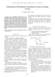
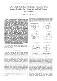
(a) The structure <strong>of</strong> a three-phase MMC<br />
C<br />
v Cai<br />
(i:1 ~ 2n)<br />
V dc<br />
(b) The structure <strong>of</strong> a module.<br />
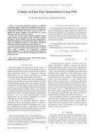
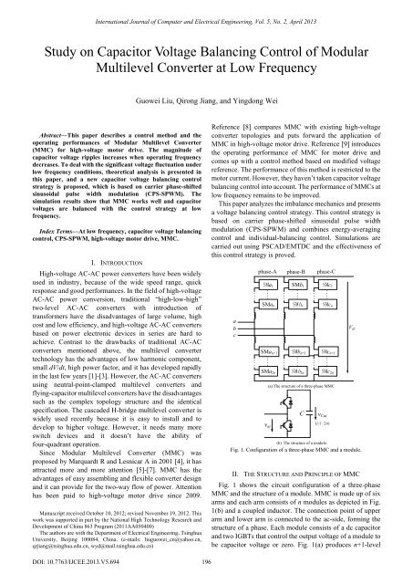
Fig. 1. C<strong>on</strong>figurati<strong>on</strong> <strong>of</strong> a three-phase MMC and a module.<br />
II. THE STRUCTURE AND PRINCIPLE OF MMC<br />
Fig. 1 shows the circuit c<strong>on</strong>figurati<strong>on</strong> <strong>of</strong> a three-phase<br />
MMC and the structure <strong>of</strong> a module. MMC is made up <strong>of</strong> six<br />
arms and each arm c<strong>on</strong>sists <strong>of</strong> n modules as depicted in Fig.<br />
1(b) and a coupled inductor. The c<strong>on</strong>necti<strong>on</strong> point <strong>of</strong> upper<br />
arm and lower arm is c<strong>on</strong>nected to the ac-side, forming the<br />
structure <strong>of</strong> a phase. Each module c<strong>on</strong>sists <strong>of</strong> a dc capacitor<br />
and two IGBTs that c<strong>on</strong>trol the output voltage <strong>of</strong> a module to<br />
be capacitor voltage or zero. Fig. 1(a) produces n+1-level<br />
DOI: 10.7763/IJCEE.2013.V5.694<br />
196
output voltage<br />
reference and carrier<br />
Internati<strong>on</strong>al Journal <strong>of</strong> Computer and Electrical Engineering, Vol. 5, No. 2, April 2013<br />
PWM waveforms since the number <strong>of</strong> module per arm is n.<br />
The difference between MMC and other voltage source<br />
c<strong>on</strong>verters is that the storage capacitor is not required at the<br />
dc-side <strong>of</strong> MMC and the energy is distributed to each<br />
module.<br />
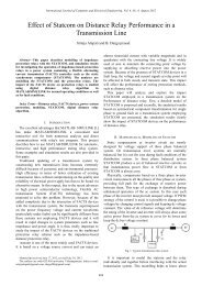
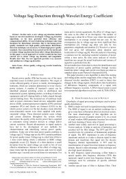
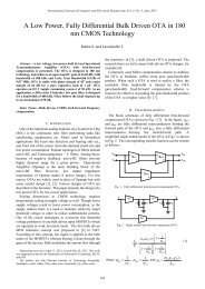
The equivalent circuit <strong>of</strong> MMC as a inverter in a high<br />
voltage frequency c<strong>on</strong>verter is shown in Fig. 2. Phase-A is<br />
taken for an example, and v ap and v an are equivalent voltage<br />
sources <strong>of</strong> upper arm and lower arm, respectively, and the<br />
resistor R in each arm represents the equivalent loss<br />
resistance. P and N are the positive and negative buses <strong>of</strong> the<br />
dc-side <strong>of</strong> MMC, respectively, and O is the neutral point. The<br />
resistor and inductor in each arm are relatively small and the<br />
voltage over it can be neglected. v ao is the voltage the output<br />
voltage <strong>of</strong> phase-A relative to the neutral point O. The<br />
following relati<strong>on</strong>ship can be obtained.<br />
III. CPS-SPWM SCHEME SUITABLE FOR MMC<br />
The capacitor voltage balancing c<strong>on</strong>trol is based <strong>on</strong><br />
CPS-SPWM. The CPS-SPWM is the most comm<strong>on</strong>ly used<br />
modulati<strong>on</strong> strategy for multilevel c<strong>on</strong>verter. When<br />
CPS-SPWM is applied, the carrier <strong>of</strong> each module uses<br />
determinate frequency, but is phase-shifted. The determinate<br />
switching frequency <strong>of</strong>fers c<strong>on</strong>venience to balance the<br />
energy in each module and estimate the power loss for real<br />
industrial applicati<strong>on</strong>s. Compared with other modulati<strong>on</strong><br />
strategies, CPS-SPWM has certain advantages in balancing<br />
the capacitor voltage. In additi<strong>on</strong>, the CPS-SPWM can<br />
reduce the generated harm<strong>on</strong>ic voltages effectively using low<br />
switching frequency.<br />
Udc/7<br />
1 1<br />
vao Vdc vap van Vdc<br />
(1)<br />
2 2<br />
The following equati<strong>on</strong> can be obtained from (1).<br />
vap van Vdc<br />
(2)<br />
0<br />
Udc<br />
We can c<strong>on</strong>clude that the output voltage <strong>of</strong> the ac-side can<br />
be determined by the numbers <strong>of</strong> modules switched <strong>on</strong> <strong>of</strong><br />
each arm, and the dc voltage is the sum <strong>of</strong> the voltages <strong>of</strong><br />
upper and lower arms. Therefore, the number <strong>of</strong> the modules<br />
switched <strong>on</strong> must be the same at any time. For an MMC with<br />
2n modules in each phase as shown <strong>on</strong> Fig. 1(a), n modules<br />
are switched <strong>on</strong> at the same time to assure a stable dc voltage;<br />
hence it produces n+1-level PWM waveforms.<br />
Because <strong>of</strong> the symmetry <strong>of</strong> the three phases and the upper<br />
and lower arm, the following current relati<strong>on</strong>ship can be<br />
obtained.<br />
1 1<br />
iap idc ia<br />
(3)<br />
3 2<br />
1 1<br />
ian idc ia<br />
(4)<br />
3 2<br />
where i ap is the current <strong>of</strong> upper arm and i an the lower, i dc is<br />
the input current at the dc-side, i a is the output current at the<br />
ac-side. The positive directi<strong>on</strong>s <strong>of</strong> the currents are shown in<br />
Fig. 2.<br />
Because <strong>of</strong> the symmetry, the principles <strong>of</strong> the three phases<br />
are the same.<br />
P<br />
a<br />
b<br />
c<br />
i ap i bp i cp<br />
v ap<br />
i a<br />
i b V dc O<br />
i c<br />
v an<br />
v bp<br />
v bn<br />
v cp<br />
v cn<br />
i an i bn i cn<br />
i dc<br />
Fig. 2. The equivalent circuit <strong>of</strong> MMC<br />
N<br />
V dc /2<br />
V dc /2<br />
0<br />
0° 90° 180° 270° 360°<br />
wt<br />
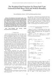
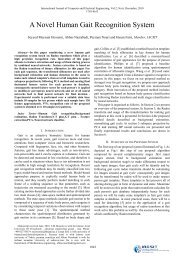
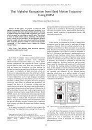
Fig. 3. Principle <strong>of</strong> carrier phase-shift modulati<strong>on</strong> (8-level).<br />
Fig. 3 shows the principle <strong>of</strong> CPS-SPWM suitable for<br />
MMC. For a leg that c<strong>on</strong>sists <strong>of</strong> a stack <strong>of</strong> n modules, these n<br />
modules use n triangular carri。ers whose phases are shifted<br />
by 2π/n from each other. The carriers <strong>of</strong> positive arm and<br />
negative arm are out <strong>of</strong> phase by π. Without loss <strong>of</strong> generality,<br />
phase-A is taken for an example. The reference voltage <strong>of</strong><br />
each module is<br />
v<br />
*<br />
ai<br />
1 * 1 1 *<br />
vap Vdc va<br />
( i 1 n)<br />
n 2n n<br />
<br />
1 * 1 1 *<br />
van Vdc va<br />
( i n 1 2 n)<br />
n 2n n<br />
where v ai * is the reference voltage <strong>of</strong> module a i and v a * is the<br />
reference line-to-neutral voltage <strong>of</strong> MMC ac side.<br />
(5)<br />
* 2<br />
va<br />
V sin t<br />
(6)<br />
3<br />
where V is the motor line-to-line rms voltage.<br />
The reference voltage <strong>of</strong> each module compares with its<br />
triangular carrier to produce pulses to drive the IGBTs.<br />
IV. CAPACITOR VOLTAGE BALANCING CONTROL IN LOW<br />
FREQUENCY CONDITION<br />
A. <strong>Capacitor</strong> <strong>Voltage</strong> Imbalance Mechanics<br />
The capacitor in the module is floating. When a module is<br />
switched <strong>on</strong>, current flowing through the capacitor causes<br />
charging and discharging and the capacitor voltage<br />
197
Internati<strong>on</strong>al Journal <strong>of</strong> Computer and Electrical Engineering, Vol. 5, No. 2, April 2013<br />
fluctuati<strong>on</strong> occurs. Because the switch-<strong>on</strong> time <strong>of</strong> each<br />
module is different, the capacitor voltage within the same<br />
arm becomes imbalanced.<br />
Reference [10] presents the theoretical analysis and<br />
mathematical deducti<strong>on</strong> <strong>of</strong> capacitor voltage fluctuati<strong>on</strong>. The<br />
results are as follows.<br />
2I<br />
8<br />
fC<br />
v Ca1<br />
f t<br />
(7)<br />
m<br />
2 cos<br />
m<br />
f t cost cost sin 2t<br />
(8)<br />
2 4<br />
where the modulati<strong>on</strong> index m, related to the ac amplitude <strong>of</strong><br />
the modulati<strong>on</strong> signal, is given by<br />
<br />
2 2V<br />
m (9)<br />
nV<br />
3<br />
C<br />
where V C is the dc comp<strong>on</strong>ent <strong>of</strong> the capacitor voltage.<br />
The following c<strong>on</strong>clusi<strong>on</strong>s are obtained from (7), (8) and<br />
(9). The magnitude <strong>of</strong> capacitor voltage fluctuati<strong>on</strong> is<br />
proporti<strong>on</strong>al to the motor current, and inversely proporti<strong>on</strong>al<br />
to the motor frequency and the capacitance, and is also<br />
affected by the modulati<strong>on</strong> index and the motor power factor.<br />
Therefore, the lower the frequency <strong>of</strong> MMC used for<br />
high-voltage motor drive, the larger the capacitor voltage<br />
fluctuati<strong>on</strong>. <strong>Capacitor</strong> voltage c<strong>on</strong>trol strategy is necessary.<br />
B. <strong>Capacitor</strong> <strong>Voltage</strong> <strong>Balancing</strong> C<strong>on</strong>trol<br />
To deal with the obvious capacitor voltage fluctuati<strong>on</strong> <strong>of</strong><br />
MMC at low frequency, this paper presents a c<strong>on</strong>trol strategy<br />
based <strong>on</strong> the theory in [10]. The capacitor voltage balancing<br />
c<strong>on</strong>trol is based <strong>on</strong> CPS-SPWM and c<strong>on</strong>sists <strong>of</strong><br />
energy-averaging c<strong>on</strong>trol and individual-balancing c<strong>on</strong>trol.<br />
<strong>Voltage</strong> outer loop<br />
*<br />
v C<br />
K<br />
+<br />
-<br />
vCa<br />
Current inner loop<br />
*<br />
K i<br />
2 aZ<br />
K<br />
*<br />
1<br />
- K3<br />
v<br />
s + s<br />
aA<br />
4<br />
+ i<br />
i 1 aZ<br />
ap<br />
+ 2<br />
i an<br />
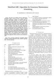
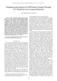
As is shown in Fig. 4(a), energy-averaging c<strong>on</strong>trol<br />
includes two closed-loops. Both loops adopt<br />
proporti<strong>on</strong>al-integral c<strong>on</strong>trol. The voltage loop enables the<br />
average voltage to follow its reference and the output is used<br />
as current reference <strong>of</strong> the current loop. The circulating<br />
current is adjusted in the current inner loop, the output <strong>of</strong><br />
which is used as the first additi<strong>on</strong>al reference voltage.<br />
The block diagram <strong>of</strong> individual-balancing c<strong>on</strong>trol is<br />
shown in Fig. 4(b). The individual-balancing c<strong>on</strong>trol forces<br />
the capacitor voltage <strong>of</strong> each module to follow its reference<br />
v * C . The difference <strong>of</strong> capacitor voltage and its reference is<br />
used as the input <strong>of</strong> a proporti<strong>on</strong>al c<strong>on</strong>troller, then multiplied<br />
by the arm current i ap (or i an ). The output is the sec<strong>on</strong>d<br />
additi<strong>on</strong>al reference voltage.<br />
The additi<strong>on</strong>al reference voltage obtained from the<br />
individual-balancing c<strong>on</strong>trol is in the same phase with the<br />
arm current. The active power injected into the module<br />
depends <strong>on</strong> the voltage difference and the arm current. The<br />
bigger the voltage difference and arm current, the str<strong>on</strong>ger<br />
the adjustment ability.<br />
Eventually, two parts <strong>of</strong> additi<strong>on</strong>al reference voltage are<br />
added to the arm reference voltage<br />
v to obtain the final<br />
reference voltage for the module a i to realize the capacitor<br />
voltage balancing c<strong>on</strong>trol.<br />
*<br />
ai<br />
v v v v<br />
(11)<br />
* * * *<br />
airef ai aA aiB<br />
V. SIMULATION RESULTS<br />
To verify the validity <strong>of</strong> the proposed c<strong>on</strong>trol strategy, the<br />
simulati<strong>on</strong> using the “PSCAD/EMTDC” s<strong>of</strong>tware package<br />
was carried out, where the circuit parameters are summarized<br />
in Table I. A high-voltage motor drive system with an 8-level<br />
MMC as the inverter was built. The role <strong>of</strong> the rectifier in the<br />
system is to c<strong>on</strong>trol the active power passing through to<br />
guarantee the steadiness <strong>of</strong> dc-link voltage and it has little to<br />
do with the fluctuati<strong>on</strong> <strong>of</strong> capacitor voltage. So the dc voltage<br />
sources are used in the dc side <strong>of</strong> MMC in the motor drive<br />
system.<br />
(a) Energy-averaging c<strong>on</strong>trol<br />
Rated line-to-line rms voltage<br />
TABLE I: CIRCUIT PARAMETERS<br />
10kV<br />
*<br />
C<br />
+<br />
v Caī<br />
(b) Individual-balancing c<strong>on</strong>trol<br />
v K 5<br />
i ap (i=1~n)<br />
*<br />
v aiB<br />
Rated apparent output<br />
Rated dc-link voltage<br />
5MVA<br />
21kV<br />
or i an (i=n+1~2n)<br />
Buffer inductance per arm<br />
DC capacitance per module<br />
10mH<br />
8000μF<br />
Fig. 4. Block diagram <strong>of</strong> capacitor voltage balancing c<strong>on</strong>trol<br />
Fig. 4(a) shows the principle <strong>of</strong> energy-averaging c<strong>on</strong>trol<br />
which forces the phase-A average voltage v Ca to follow<br />
*<br />
capacitor voltage reference v C . C<strong>on</strong>sequently energy is<br />
distributed into each module averagely. The phase-A average<br />
voltage v Ca can be obtained by<br />
v<br />
Ca<br />
2n<br />
1<br />
vCai<br />
(10)<br />
2<br />
n i 1<br />
Rated capacitor dc voltage per module<br />
3kV<br />
Number <strong>of</strong> modules per arm per phase (n) 7<br />
Carrier frequency per module<br />
2000Hz<br />
TABLE II: SPECIFICATIONS OF THE SQUIRREL CAGE INDUCTION MACHINE<br />
Rated line-to-line rms voltage<br />
10kV<br />
Rated line-to-line rms current<br />
0.5kA<br />
Rated frequency<br />
30Hz<br />
198
u/kV<br />
u/kV<br />
i/kA<br />
i/kA<br />
u/kV<br />
u/kV<br />
u/kV<br />
u/kV<br />
u/kV<br />
u/kV<br />
u/kV<br />
Internati<strong>on</strong>al Journal <strong>of</strong> Computer and Electrical Engineering, Vol. 5, No. 2, April 2013<br />
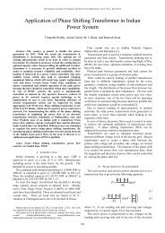
A. Effectiveness <strong>of</strong> <strong>Capacitor</strong> <strong>Voltage</strong> <strong>Balancing</strong> C<strong>on</strong>trol<br />
The MMC ac-side output frequency is set as 20Hz. A<br />
5MVA R-L load is used as steady state approximati<strong>on</strong> <strong>of</strong> a<br />
motor, the power factor <strong>of</strong> which is set as 0.8. The capacitor<br />
voltage balancing c<strong>on</strong>trol strategy is applied at 0.35s. The<br />
simulati<strong>on</strong> results are shown in Fig. 5.<br />
Fig. 5 dem<strong>on</strong>strates the change <strong>of</strong> capacitor voltage,<br />
ac-side output voltage and arm current <strong>of</strong> before and after the<br />
c<strong>on</strong>trol strategy is applied. As shown in Fig. 5, after the<br />
c<strong>on</strong>trol strategy is applied, the fluctuati<strong>on</strong> <strong>of</strong> module<br />
decreases obviously, from 23% down to 7%, and the ac-side<br />
harm<strong>on</strong>ic voltages <strong>of</strong> MMC are reduced effectively. Because<br />
<strong>of</strong> current inner loop <strong>of</strong> energy-averaging c<strong>on</strong>trol, the<br />
circulating current between the upper and lower arms<br />
decreases, which c<strong>on</strong>tributes to reducing losses.<br />
4<br />
3.5<br />
3<br />
2.5<br />
2<br />
a 相 子 模 块 电 容 电 压<br />
0.25 0.3 0.35 0.4 0.45 0.5 0.55 0.6<br />
t/s<br />
234<br />
0.3 (a) The 0.35 capacitor voltages t/s <strong>of</strong> phase-A 0.4 0.45<br />
15<br />
10<br />
5<br />
0<br />
-5<br />
a 相 子 模 块 电 容 电 压<br />
-10<br />
234<br />
0.3 0.35 t/s 0.4 0.45<br />
-15<br />
0.3 -10<br />
0.35 0.4 0.45<br />
0.3 0.35 t/s 0.4 0.45<br />
(b) The 交 output 流 侧 输 voltages 出 电 流 和 桥 <strong>of</strong> 臂 电 ac-side 流<br />
-2 02 1.5<br />
0.31<br />
0.35 0.4 0.45<br />
i t/s<br />
0.5<br />
ap<br />
i an<br />
0<br />
-0.5<br />
-1<br />
-1.5<br />
0.3 0.35 0.4 0.45<br />
t/s<br />
(c) the output current <strong>of</strong> phase-A (ia) and its arm currents (iap for the upper<br />
arm and ian for the lower)<br />
Fig. 5. The effectiveness <strong>of</strong> capacitor voltage balancing c<strong>on</strong>trol<br />
B. Performance Under Dynamic State<br />
The MMC ac-side output frequency is set as 30Hz. A<br />
squirrel cage inducti<strong>on</strong> machine model is used as a motor, the<br />
specificati<strong>on</strong>s <strong>of</strong> which are summarized in Table II. The<br />
capacitor voltage balancing c<strong>on</strong>trol strategy is applied the<br />
whole time. The load torque is set as 0.4pu and the system has<br />
reached steady-state before 2s, when it increases to 0.6pu.<br />
The simulati<strong>on</strong> results are shown in Fig. 6.<br />
As shown in Fig. 6, after the load torque increases, the<br />
capacitor voltage doesn’t lose its balance. Because <strong>of</strong> the<br />
increase <strong>of</strong> output power, the ac-side currents and arm<br />
currents increase and the fluctuati<strong>on</strong>s <strong>of</strong> capacitor voltages<br />
increase to 4%, still in the allowable range. The capacitor<br />
voltage balancing c<strong>on</strong>trol possesses good performance under<br />
dynamic state.<br />
C. Performance when a Fault Occurs at Dc-Side<br />
The MMC ac-side output frequency is set as 30Hz and a<br />
squirrel cage inducti<strong>on</strong> machine model is used as a motor.<br />
The capacitor voltage balancing c<strong>on</strong>trol strategy is applied<br />
i a<br />
and the load torque is set as 0.8pu the whole time. The<br />
steady-state has been reached before 1s, when the MMC<br />
dc-side voltage reference decreases to 18kV from 21kV. The<br />
simulati<strong>on</strong> results are shown in Fig. 7.<br />
i/kA<br />
3.2<br />
3.1<br />
3<br />
2.9<br />
2.8<br />
a 相 子 模 块 电 容 电 压<br />
2.7<br />
1.8 1.9 2 2.1 2.2 2.3<br />
t/s<br />
10<br />
5<br />
0<br />
-5<br />
(a) The capacitor 交 流 侧 voltages 输 出 电 <strong>of</strong> 压 phase-A<br />
-10<br />
1.8 1.9 2 2.1 2.2 2.3<br />
t/s<br />
(b) The output voltages <strong>of</strong> ac-side<br />
1<br />
0.5<br />
0<br />
-0.5<br />
i an<br />
i a<br />
i ap<br />
-1<br />
1.8 1.9 2 2.1 2.2 2.3<br />
t/s<br />
(c) The output current <strong>of</strong> phase-A (ia) and its arm currents (iap for the upper<br />
arm and ian for the lower)<br />
P/MW Q/Mvar<br />
i/kA<br />
10<br />
8<br />
6<br />
4<br />
2<br />
1.6 1.8 2 2.2 2.4 2.6<br />
t/s<br />
(d) The output active power (P) and reactive power (Q)<br />
3.2<br />
3<br />
2.8<br />
2.6<br />
2.4<br />
Fig. 6. Performance under dynamic state<br />
a 相 子 模 块 电 容 电 压<br />
P<br />
2.2<br />
0.8 0.9 1 1.1 1.2 1.3<br />
t/s<br />
(a) The capacitor 交 流 侧 voltages 输 出 电 <strong>of</strong> 压 phase-A<br />
10<br />
5<br />
0<br />
-5<br />
-10<br />
0.8 0.9 1 1.1 1.2 1.3<br />
t/s<br />
(b) The output voltages <strong>of</strong> ac-side<br />
1<br />
i an<br />
0.5<br />
0<br />
-0.5<br />
i a<br />
i ap<br />
-1<br />
0.8 0.9 1 1.1 1.2 1.3<br />
t/s<br />
(c) The output current <strong>of</strong> phase-A (ia) and its arm currents (iap for the upper<br />
arm and ian for the lower)<br />
Q<br />
199
Internati<strong>on</strong>al Journal <strong>of</strong> Computer and Electrical Engineering, Vol. 5, No. 2, April 2013<br />
P/MW Q/Mvar<br />
10<br />
5<br />
0<br />
P<br />
Q<br />
-5<br />
0.8 0.9 1 1.1 1.2 1.3 1.4 1.5 1.6<br />
t/s<br />
(d) The output active power (P) and reactive power (Q)<br />
Fig. 7. Performance when a fault occurs at dc-side<br />
As shown in Fig. 7, because <strong>of</strong> the capacitor voltage<br />
balancing c<strong>on</strong>trol, the capacitor voltage keeps its balance and<br />
reaches its new steady-state immediately after the dc voltage<br />
reference decreases, with the fluctuati<strong>on</strong>s about 5%. The<br />
c<strong>on</strong>trol strategy c<strong>on</strong>tributes to keeping capacitor voltage<br />
balanced when a fault occurs at the dc-side <strong>of</strong> MMC.<br />
VI. CONCLUSION<br />
Through theoretically analyzing the imbalance <strong>of</strong><br />
capacitor voltage, the relati<strong>on</strong> between the voltage<br />
fluctuati<strong>on</strong>, ac-side current, frequency and the capacitance is<br />
obtained.<br />
To enhance the performance <strong>of</strong> MMC in low frequency<br />
c<strong>on</strong>diti<strong>on</strong>, a voltage balancing c<strong>on</strong>trol strategy based <strong>on</strong><br />
CPS-SPWM is proposed in this paper. The c<strong>on</strong>trol strategy<br />
combines energy-averaging c<strong>on</strong>trol and individual-balancing<br />
c<strong>on</strong>trol and it can maintain capacitor voltage balance at low<br />
switching frequency.<br />
The simulati<strong>on</strong> <strong>of</strong> a high-voltage motor drive system with<br />
an 8-level MMC as the inverter <strong>on</strong> the platform <strong>of</strong><br />
PSCAD/EMTDC was carried out. The simulati<strong>on</strong> results<br />
dem<strong>on</strong>strate that the capacitor voltage balancing c<strong>on</strong>trol is<br />
effective in low frequency c<strong>on</strong>diti<strong>on</strong> and possesses good<br />
performance under dynamic state.<br />
REFERENCES<br />
[1] J. Rodriguez, L. J. Sheng and Z. P. Fang, "Multilevel inverters: a survey<br />
<strong>of</strong> topologies, c<strong>on</strong>trols, and applicati<strong>on</strong>s," Industrial Electr<strong>on</strong>ics, IEEE<br />
Transacti<strong>on</strong>s, vol.49, pp. 724-738, 2002.<br />
[2] S. Bernet, "Recent developments <strong>of</strong> high power c<strong>on</strong>verters for industry<br />
and tracti<strong>on</strong> applicati<strong>on</strong>s," Power Electr<strong>on</strong>ics, IEEE Transacti<strong>on</strong>s,<br />
vol.15, pp. 1102-1117, 2000.<br />
[3] W. Chenchen and L. Y<strong>on</strong>d<strong>on</strong>g, "A survey <strong>on</strong> topologies <strong>of</strong> multilevel<br />
c<strong>on</strong>verters and study <strong>of</strong> two novel topologies," in Proc. 2009 Power<br />
Electr<strong>on</strong>ics and Moti<strong>on</strong> C<strong>on</strong>trol C<strong>on</strong>ference, 2009. IPEMC '09. IEEE<br />
6th Internati<strong>on</strong>al, pp. 860-865.<br />
[4] A. Lesnicar and R. Marquardt, "An innovative modular multilevel<br />
c<strong>on</strong>verter topology suitable for a wide power range," in Proc. 2003<br />
Power Tech C<strong>on</strong>ference Proceedings, 2003 IEEE Bologna, pp. 3-6.<br />
[5] S. Allebrod, R. Hamerski, and R. Marquardt, "New transformerless,<br />
scalable <strong>Modular</strong> Multilevel C<strong>on</strong>verters for HVDC-transmissi<strong>on</strong>," in<br />
Proc. 2008 Power Electr<strong>on</strong>ics Specialists C<strong>on</strong>ference, 2008. PESC<br />
2008. IEEE, pp. 174-179.<br />
[6] M. Glinka, "Prototype <strong>of</strong> multiphase modular-multilevel-c<strong>on</strong>verter<br />
with 2 MW power rating and 17-level-output-voltage," in Proc. 2004<br />
Power Electr<strong>on</strong>ics Specialists C<strong>on</strong>ference, 2004. PESC 04. 2004 IEEE<br />
35th Annual, pp. 2572-2576.<br />
[7] M. Glinka and R. Marquardt, "A new AC/AC multilevel c<strong>on</strong>verter<br />
family," Industrial Electr<strong>on</strong>ics, IEEE Transacti<strong>on</strong>s, vol.52, pp.<br />
662-669, 2005.<br />
[8] M. Hiller, D. Krug, R. Sommer, and S. Rohner, "A new highly modular<br />
medium voltage c<strong>on</strong>verter topology for industrial drive applicati<strong>on</strong>s,"<br />
in Proc. 2009 Power Electr<strong>on</strong>ics and Applicati<strong>on</strong>s, 2009. EPE '09. 13th<br />
European C<strong>on</strong>ference <strong>on</strong>, pp. 1-10.<br />
[9] M. Hagiwara, K. Nishimura, and H. Akagi, "A Medium-<strong>Voltage</strong> Motor<br />
Drive With a <strong>Modular</strong> Multilevel PWM Inverter," Power Electr<strong>on</strong>ics,<br />
IEEE Transacti<strong>on</strong>, vol. 25, pp. 1786-1799, 2010.<br />
[10] M. Hagiwara, K. Nishimura, and H. Akagi, "A Medium-<strong>Voltage</strong> Motor<br />
Drive With a <strong>Modular</strong> Multilevel PWM Inverter," Power Electr<strong>on</strong>ics,<br />
IEEE Transacti<strong>on</strong>s, vol. 25, pp. 1786-1799, 2010.<br />
Guowei Liu was born in Lia<strong>on</strong>ing, China, in 1988. He<br />
graduated from Department <strong>of</strong> Electrical Engineering for<br />
Bachelor Degree in Tsinghua University, China, and now<br />
he is a Master candidate for Electrical Engineering in<br />
Tsinghua University. His special fields <strong>of</strong> interest included<br />
high power electr<strong>on</strong>ics and power quality c<strong>on</strong>trol.<br />
Qir<strong>on</strong>g Jiang was born in Hunan, China, in 1969. He<br />
received the B.S. and Ph.D. degree in Electrical<br />
Engineering from Tsinghua University, Beijing, China, in<br />
1992 and 1997 respectively. He is currently a Pr<strong>of</strong>essor in<br />
the Department <strong>of</strong> Electrical Engineering, Tsinghua<br />
University. His research interests include Power System<br />
Analysis and C<strong>on</strong>trol, Modeling and C<strong>on</strong>trol <strong>of</strong> Flexible<br />
AC Transmissi<strong>on</strong> Systems, Power Quality Analysis and<br />
Mitigati<strong>on</strong>, Power Electr<strong>on</strong>ic Equipments, Renewable<br />
Energy Power C<strong>on</strong>versi<strong>on</strong><br />
Yingd<strong>on</strong>g Wei was born in Henan, China, in 1979. He<br />
received the B.S. and M.S. degrees from the College <strong>of</strong><br />
Electrical Engineering, Zhejiang University, Hangzhou,<br />
China, in 2002 and 2005, respectively, and the Ph.D. degree<br />
from the Department <strong>of</strong> Electrical Engineering, Tsinghua<br />
University, Beijing, China, in 2009. His research interests<br />
include C<strong>on</strong>trol, Modeling and C<strong>on</strong>trol <strong>of</strong> Flexible AC<br />
Transmissi<strong>on</strong> Systems, Power Quality Analysis and<br />
Mitigati<strong>on</strong>, Power Electr<strong>on</strong>ic Equipments.<br />
200