view full paper - Ijsrp.org
view full paper - Ijsrp.org
view full paper - Ijsrp.org

You also want an ePaper? Increase the reach of your titles
YUMPU automatically turns print PDFs into web optimized ePapers that Google loves.
International Journal of Scientific and Research Publications, Volume 3, Issue 3, March 2013 1<br />
ISSN 2250-3153<br />
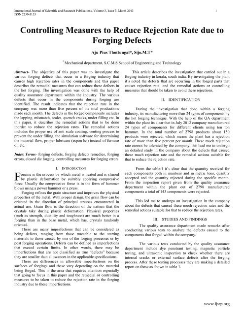
Controlling Measures to Reduce Rejection Rate due to<br />
F<strong>org</strong>ing Defects<br />
Aju Pius Thottungal*, Sijo.M.T*<br />
*<br />
Mechanical department, S.C.M.S.School of Engineering and Technology<br />
Abstract- The objective of this <strong>paper</strong> was to investigate the<br />
various f<strong>org</strong>ing defects that occur in a f<strong>org</strong>ing industry that<br />
causes high rejection rates in the components and this <strong>paper</strong><br />
describes the remedial measures that can reduce these defects in<br />
the hot f<strong>org</strong>ing. The investigation was done with the help of<br />
quality assurance department within the industry. The various<br />
defects that occur in the components during f<strong>org</strong>ing are<br />
identified. The result indicates that the rejection rate in the<br />
company was more than five percent of the total productions<br />
made each month. The defects in the f<strong>org</strong>ed components includes<br />
the lapping, mismatch, scales, quench cracks, under filling etc. In<br />
this <strong>paper</strong>, it describes the remedial actions that to be done<br />
inorder to reduce the rejection rates. The remedial actions<br />
includes the proper use of anti scale coating, venting process to<br />
prevent the under filling, the simulation software for determining<br />
the material flow, proper lubricant (espon lss) instead of furnace<br />
oil etc.<br />
Index Terms- f<strong>org</strong>ing defects, f<strong>org</strong>ing defects remedies, f<strong>org</strong>ing<br />
errors, closed die f<strong>org</strong>ing, controlling measures for f<strong>org</strong>ing errors<br />
F<br />
I. INTRODUCTION<br />
<strong>org</strong>ing is the process by which metal is heated and is shaped<br />
by plastic deformation by suitably applying compressive<br />
force. Usually the compressive force is in the form of hammer<br />
blows using a power hammer or a press.<br />
F<strong>org</strong>ing refines the grain structure and improves the physical<br />
properties of the metal. With proper design, the grain flow can be<br />
oriented in the direction of principal stresses encountered in<br />
actual use. Grain flow is the direction of the pattern that the<br />
crystals take during plastic deformation. Physical properties<br />
(such as strength, ductility and toughness) are much better in a<br />
f<strong>org</strong>ing than in the base metal, which has, crystals randomly<br />
oriented.<br />
There are many imperfections that can be considered as<br />
being defects, ranging from those traceable to the starting<br />
materials to those caused by one of the f<strong>org</strong>ing processes or by<br />
post f<strong>org</strong>ing operations. Defects can be defined as imperfections<br />
that exceed certain limits. In other words, there may be<br />
imperfections that are not classified as true “defects” because<br />
they are smaller than allowances in the applicable specifications.<br />
There are differences in allowable imperfections on the<br />
surfaces of f<strong>org</strong>ings and these vary depending on the material<br />
being f<strong>org</strong>ed. This is the area that requires attention especially<br />
that going to focus in this <strong>paper</strong> and the remedial or controlling<br />
measures to be taken to reduce the rejection rate in the f<strong>org</strong>ing<br />
industry due to these imperfections.<br />
This article describes the investigation that carried out in a<br />
f<strong>org</strong>ing industry in kerala, south india. By investigating the plant<br />
it‟s noted the defects that are occurring in the f<strong>org</strong>ed parts that<br />
causes rejection rate, and the remedial actions or controlling<br />
measures that should be taken to avoid these rejections.<br />
II. IDENTIFICATION<br />
During the investigation that done within a f<strong>org</strong>ing<br />
industry, its manufacturing more than 24 types of components by<br />
the hot f<strong>org</strong>ing technique. With the help of the QA department<br />
within the plant its clear that in July 2012 company manufactured<br />
24 types of components for different clients using ten ton<br />
hammer. In the total number of 2798 products about 150<br />
products were rejected, which means the plant has a rejection<br />
rate of more than five percent per month. These much rejection<br />
rate cannot be tolerated by the company, this lead me to undergo<br />
an detailed study in the company about the defects that caused<br />
these much rejection rate and the remedial actions suitable for<br />
that to reduce the rejection rate.<br />
From the table:1 it‟s clear that the quantity received for<br />
each components both in numbers and in metric tons, quantity<br />
accepted and the quantity rejected during the specific month.<br />
From the inspection report given from the quality assurance<br />
department within the plant out of 2798 manufactured<br />
components a total of 143 components were rejected.<br />
This led me to undergo an investigation in the company<br />
about the defects that caused these much rejection rates and the<br />
remedial actions suitable for that to reduce the rejection rates.<br />
III. STUDIES AND FINDINGS<br />
The quality assurance department made remarks after<br />
conducting various tests to analyze the defects caused to the<br />
components that f<strong>org</strong>ed within the company.<br />
The various tests conducted by the quality assurance<br />
department include dye penetrant testing, magnetic particle<br />
testing, and ultrasonic inspection to check whether there are<br />
internal cracks or external surface defects after the f<strong>org</strong>ing<br />
process. After these testing processes they are making a detailed<br />
report on these as shown in table 1.<br />
www.ijsrp.<strong>org</strong>
International Journal of Scientific and Research Publications, Volume 3, Issue 3, March 2013 2<br />
ISSN 2250-3153<br />
INSPECTION REPORT FOR MONTH JULY 2012<br />
Sl no. item<br />
Quantity<br />
received<br />
Quantity<br />
accepted<br />
Qty<br />
rejec<br />
ted<br />
No.s M No.s M No.s<br />
tons tons<br />
1 680 bevel 119 16.0 118 15.9 1<br />
pinion<br />
7<br />
3<br />
2 786 crank shaft 155 17.8 155 17.8 0<br />
gear<br />
3<br />
3<br />
3 254 saddle 101 11.1 62 6.82 39<br />
1<br />
4 833 coupling 42 3.23 39 3 3<br />
5 819 pylon 20 0.59 18 .53 2<br />
6 621 saddle 10 1.55 10 1.55 0<br />
7 807 integral 58 10.2 58 10.2 0<br />
axle arm<br />
1<br />
1<br />
8 794 cam shaft 55 3.96 55 3.96 0<br />
gear<br />
9 256 crank shaft 39 2.34 39 2.34 0<br />
gear<br />
10 496 rod wheel 180 7.38 180 7.38 0<br />
arm<br />
11 175 con rod 635 25.8 549 22.3 86<br />
4<br />
4<br />
12 855 gear 25 11.2 20 9 5<br />
5<br />
13 55 valve body 200 21.4 200 21.4 0<br />
14 263 cam shaft 81 11.3 81 11.3 0<br />
gear<br />
4<br />
4<br />
15 837 gear 55 18.1 54 17.8 1<br />
5<br />
2<br />
16 814 companion 63 4.28 63 4.28 0<br />
flange<br />
17 779 gear 250 14.8 250 14.8 0<br />
8<br />
8<br />
18 958 mf center 37 4.51 37 4.51 0<br />
19 959 mf inter 15 1.38 15 1.38 0<br />
20 960 mf end 15 1.58 15 1.58 0<br />
21 527 d cage 113 2.6 111 2.55 2<br />
22 127 valve body 200 36.6 200 36.6 0<br />
23 219 mb cap 285 19.3 281 19.3 4<br />
8<br />
8<br />
24 272 gear 45 8.28 45 8.28 0<br />
total 2798 255. 2655 244. 143<br />
74<br />
89<br />
Table 1: inspection report by the QA department for month July<br />
By plotting the defects that caused on the components<br />
graphically the figure 1 shows it. From the graph we can get a<br />
clear idea that out of 24 components a total of 14 components are<br />
affected by the unfilling and scale pits which are the major<br />
defects. The other major defects are mismatch, lapping, oversize<br />
in the f<strong>org</strong>ed components.<br />
Figure 1: graphical representation defects presented in the<br />
components<br />
IV. TECHNIQUES USED BY QUALITY ASSURANCE<br />
DEPARTMENT TO ANALYZE THE DEFECTS<br />
DURING FORGING<br />
A: GREEN STAGE<br />
There are several techniques that used for check the<br />
defects that caused in that f<strong>org</strong>ed components. It may be in hot<br />
stage or it may be in green stage. The green stage checking is<br />
done after the f<strong>org</strong>ed components are cooled.<br />
1. Dye penetrant inspection<br />
2. Magnetic particle inspection<br />
3. Ultrasonic inspection<br />
1. DYE PENETRANT INSPECTION<br />
Dye penetrant inspection (DPI), also called liquid<br />
penetrant inspection (LPI) or penetrant testing (PT), is a widely<br />
applied and low-cost inspection method used to locate surfacebreaking<br />
defects in all non-porous materials (metals, plastics, or<br />
ceramics). The penetrant may be applied to all non-ferrous<br />
materials and ferrous materials; although for ferrous<br />
components magnetic-particle inspection is often used instead for<br />
its subsurface detection capability. LPI is used to detect casting,<br />
f<strong>org</strong>ing and welding surface defects such as hairline cracks,<br />
surface porosity, leaks in new products, and fatigue cracks on inservice<br />
components.<br />
2. MAGNETIC PARTICLE INSPECTION<br />
Magnetic particle inspection (MPI) is a non-destructive<br />
testing (NDT) process for detecting surface and slightly<br />
subsurface discontinuities in ferroelectric materials such<br />
as iron, nickel, cobalt, and some of their alloys. The process puts<br />
a magnetic field into the part. The piece can be magnetized by<br />
direct or indirect magnetization. Direct magnetization occurs<br />
when the electric current is passed through the test object and a<br />
magnetic field is formed in the material. Indirect magnetization<br />
www.ijsrp.<strong>org</strong>
International Journal of Scientific and Research Publications, Volume 3, Issue 3, March 2013 3<br />
ISSN 2250-3153<br />
occurs when no electric current is passed through the test object,<br />
but a magnetic field is applied from an outside source. The<br />
magnetic lines of force are perpendicular to the direction of the<br />
electric current which may be either alternating current (AC) or<br />
some form of direct current (DC) (rectified AC). The presence of<br />
a surface or subsurface discontinuity in the material allows<br />
the magnetic flux to leak, since air cannot support as much<br />
magnetic field per unit volume as metals. Ferrous iron particles<br />
are then applied to the part. The particles may be dry or in a wet<br />
suspension. If an area of flux leakage is present the particles will<br />
be attracted to this area. The particles will build up at the area of<br />
leakage and form what is known as an indication. The indication<br />
can then be evaluated to determine what it is, what may have<br />
caused it, and what action should be taken, if any.<br />
There are several techniques that used for check the<br />
defects that caused in that f<strong>org</strong>ed components .Hot stage<br />
checking consists of the analysis of f<strong>org</strong>ed part at the stage of<br />
f<strong>org</strong>ing itself. In this it will thoroughly inspect the laps, scale<br />
pits, unfilling, cracks, and mismatch by directly. And for control<br />
the dimensions we will use the GO and NO-GO gauges.<br />
DEFECTS DURING FORGING ANALYZED BY THE<br />
QUALITY ASSURANCE DEPARTMENT<br />
1. UNFILLED SECTION<br />
Some section of the die cavity is not completely filled by the<br />
flowing metal or Metal does not fill the recesses of the die<br />
completely. Its mainly due to the improper design of the die. This<br />
unfilling process is occurring due to following.<br />
• improper design of the f<strong>org</strong>ing die .<br />
• improper material flow in the die.<br />
• air, gas or lubricant being trapped in a corner feature of<br />
a f<strong>org</strong>ing dies.<br />
2. LAPS AND FOLD<br />
Figure 2: magnetic particle inspection<br />
3. ULTRASONIC TESTING<br />
In ultrasonic testing, an ultrasound transducer connected<br />
to a diagnostic machine is passed over the object being inspected.<br />
The transducer is typically separated from the test object by a<br />
couplant (such as oil) or by water, as in immersion testing.There<br />
are two methods of receiving the ultrasound waveform, reflection<br />
and attenuation. In reflection (or pulse-echo) mode, the<br />
transducer performs both the sending and the receiving of the<br />
pulsed waves as the "sound" is reflected back to the device.<br />
Reflected ultrasound comes from an interface, such as the back<br />
wall of the object or from an imperfection within the object. The<br />
diagnostic machine displays these results in the form of a signal<br />
with an amplitude representing the intensity of the reflection and<br />
the distance, representing the arrival time of the reflection. In<br />
attenuation (or through-transmission) mode, a transmitter sends<br />
ultrasound through one surface, and a separate receiver detects<br />
the amount that has reached it on another surface after traveling<br />
through the medium. Imperfections or other conditions in the<br />
space between the transmitter and receiver reduce the amount of<br />
sound transmitted, thus revealing their presence. Using the<br />
couplant increases the efficiency of the process by reducing the<br />
losses in the ultrasonic wave energy due to separation between<br />
the surfaces.<br />
B: HOT STAGE<br />
A lap is defined as surface to surface contact in the<br />
workpiece when the surface of the workpiece folds or collapses<br />
on itself. A section of the workpiece flowing into itself.A “flowby”<br />
in which the workpiece surface is in contact with a die and is<br />
subsequently pulled away by a tensile stress component and<br />
closes on itself.“Peeling” that can form when the surface of a<br />
billet or preform is sheared by a die, resulting in an area of<br />
localized folding. A die corner is frequently involved, as it forces<br />
material ahead of a moving contact region, without significant<br />
subsurface deformation. This defect can be the result of a poor<br />
design or inadequate process control.<br />
Figure 3: laps formed in the component during f<strong>org</strong>ing<br />
3. SCALE PITS<br />
The oxidation and decarburization of steel take place when<br />
steel components are heated in the presence of air or products of<br />
combustion. Undesired and excessive oxidation can lead to<br />
problems such as scale pit marks, dimensional changes, poor<br />
surface finish, rejections and quench cracking. Additionally,<br />
these problems may lead to the need for expensive operations<br />
like shot blasting, machining and acid pickling. Protection<br />
against scaling and decarburization is achieved by heating in<br />
molten salts, fluidized-bed furnaces, protective gaseous media or<br />
vacuum. These measures demand heavy capital investment,<br />
www.ijsrp.<strong>org</strong>
International Journal of Scientific and Research Publications, Volume 3, Issue 3, March 2013 4<br />
ISSN 2250-3153<br />
highly skilled personnel and special safety precautions. Many<br />
companies cannot afford them, yet they are under mounting<br />
pressure to prevent oxidation and decarburization.<br />
4. QUENCH CRACKS<br />
F<strong>org</strong>ings such as knuckle joints and crankshafts, when heat<br />
treated in furnaces of oxidizing atmosphere, are susceptible to<br />
quench cracking. Quench cracks appear when stresses generated<br />
during quenching are greater than the tensile strength of thin<br />
sections of the f<strong>org</strong>ing. Chrome-moly grades of steel are most<br />
susceptible to quench cracks, which usually occur in the gear-end<br />
portion of the crankshaft. By coating the gear-end with an antiscale<br />
coating, the cracking is prevented.<br />
Figure 3: cause and effect diagram for the rejection rate<br />
The figure shows the cause and effect diagram of the<br />
f<strong>org</strong>ing defects and its causes as shown in the figure 3.<br />
Figure2: Quench cracks<br />
<br />
<br />
<br />
Overheating during the austenitizing portion of the heat<br />
treatment cycle can coarsen normally fine grained<br />
steels. coarse grained steels increase hardening depth<br />
and are more prone to quench cracking than fine grain<br />
steels. Avoid overheating and overly long dwell times<br />
while austenitizing.<br />
Improper quenchant. Yes, water, brine, or caustic will<br />
get the steel “harder.” If the steel is an oil hardening<br />
steel, the use of these overly aggressive quenchants will<br />
lead to cracking.<br />
Too much time between the quenching and the<br />
tempering of the heat treated parts. A common<br />
misconception is that quench cracks can occur only<br />
while the piece is being quenched. This is not true. If<br />
the work is not tempered right away, quench cracks can<br />
(and will) occur.<br />
5. MISMATCH<br />
Mismatch is occurring due to the deflection or the<br />
movements caused in the upper die and lower die from its<br />
centre due to the repeated blows. The die here is examined<br />
after a large batch of components being f<strong>org</strong>ed. We have to<br />
examine the die, its position periodically to identify the<br />
deflection caused in the dies.<br />
V. RESULTS AND DISCUSSIONS<br />
REMEDIAL ACTIONS TO BE TAKEN<br />
1. USE ANTI-SCALE COATING<br />
An anti-scale coating, which we call ESPON, is applied<br />
on components or billets to be heated before charging them into<br />
the furnace. Care is taken to apply a uniform coating by<br />
brushing, dipping or spraying. The coating is then allowed to dry<br />
for 30 minutes at ambient temperature of 35°C. This anti-scale<br />
coating acts as a barrier to the basic reactions of oxidation and<br />
decarburization. To prevent scaling and decarburization, care is<br />
taken to apply a uniform coating layer on the component. The<br />
coating also reduces decarburization on billets and ingots during<br />
hot-f<strong>org</strong>ing and hot-rolling operations. Heat transfer from the<br />
heating medium to the metal is unaffected by the coating.<br />
Additionally, the coating has no reaction with the steel surface<br />
and no release of toxic fumes during use, heat treatment or<br />
storage. The coating is nonhazardous and economical to use.<br />
Benefits:<br />
<br />
<br />
Prevention of Quench Cracks – F<strong>org</strong>ings such as<br />
knuckle joints and crankshafts, when heat treated in<br />
furnaces of oxidizing atmosphere, are susceptible to<br />
quench cracking. Quench cracks appear when stresses<br />
generated during quenching are greater than the tensile<br />
strength of thin sections of the f<strong>org</strong>ing. Chrome-moly<br />
grades of steel are most susceptible to quench cracks,<br />
which usually occur in the gear-end portion of the<br />
crankshaft.By coating the gear-end with an anti-scale<br />
coating, the cracking is prevented.<br />
Reduction in Shot-Blasting Time - After Heat<br />
Treatment Operations like shot blasting, grinding and<br />
pickling are expensive and time-consuming procedures.<br />
They are necessary to remove scaling from components<br />
and to enhance the product‟s aesthetic appeal, but they<br />
do not add value to the product. These operations can be<br />
substantially reduced if a coating is applied to<br />
components before heat treatment.<br />
www.ijsrp.<strong>org</strong>
International Journal of Scientific and Research Publications, Volume 3, Issue 3, March 2013 5<br />
ISSN 2250-3153<br />
<br />
Reducing Decarburization During Hot F<strong>org</strong>ing and Hot<br />
Rolling – During the hot rolling of special grades of<br />
steel in which decarburization needs to be kept in check,<br />
unforeseen conditions like mill breakdown and<br />
unplanned downtime may arise. Even when the plant is<br />
closed for a weekly holiday, the furnace may be shut off<br />
abruptly, leaving billets inside. Billets left in the furnace<br />
are subjected to prolonged heating, leading to<br />
decarburization. Applying an anti-scale coating ensures<br />
that billets are protected from decarburization.<br />
2. VENTING TO PREVENT UNDERFILLING<br />
Underfilling is typically a problem when a large part is<br />
manufactured on a small press with a less-than-optimum preform<br />
geometry. Smaller equipment does not provide the option of<br />
overpowering a less-than-optimum design or leave much margin<br />
for process variation. Depending on the equipment, force, power,<br />
speed or energy can be the culprit for an underfill. a steel f<strong>org</strong>ing<br />
being produced on an undersized hydraulic press. Because the<br />
press is slow, there is significant chilling of the work piece, as<br />
indicated by the temperature profiles in the figure. This causes<br />
the flow strength of the steel to increase and require more force<br />
to deform it. Because of its small size, the press will stall before<br />
the component is completely f<strong>org</strong>ed, leaving an underfilled<br />
region. To avoid this, equipment of the right capacity must be<br />
used.<br />
Venting: Underfills can also result from air, gas or lubricant<br />
being trapped in a corner feature of a f<strong>org</strong>ing. These can be<br />
eliminated by a redesigned preform, which provides a vent for<br />
gas, or by adding corner closure to the final f<strong>org</strong>ing. The ideal<br />
gas law can be used to describe the behavior of gas being<br />
compressed in a die corner<br />
3.USE SIMULATION SOFTWARE FOR THE MATERIAL<br />
FLOW<br />
During open-die f<strong>org</strong>ing or f<strong>org</strong>ing without any die<br />
contact, the work piece may flow in a manner that is different<br />
from the design plan. Even though we would like the material to<br />
flow in a prescribed manner, if it is unconstrained it may move in<br />
an undesirable fashion, leaving a part that does not meet the<br />
customer's specifications. This type of material movement is not<br />
random or arbitrary and will take the path of least resistance in<br />
determining its flow. Simulation programs can aid the f<strong>org</strong>er in<br />
understanding actual material flow. These packages incorporate<br />
the flow along the path of least resistance within their<br />
calculations and provide a detailed <strong>view</strong> of the actual geometry<br />
that a part would take when the dies do not provide constraint.<br />
Simulation programs: It can be effectively used to see<br />
the formation of defects. These tools allow the f<strong>org</strong>er to "see"<br />
inside the die and the work piece during deformation. The<br />
simulation tool can also provide a serial <strong>view</strong> of the process<br />
dynamics in both forward and backward directions. These can<br />
provide the f<strong>org</strong>er with significant insights into the origin and<br />
evolution of the geometrical defects that are described in this<br />
<strong>paper</strong>.<br />
Simulation has allowed us to clearly illustrate die<br />
designs that contribute to geometrical defects of laps and<br />
underfills. The programs also allow the f<strong>org</strong>ing engineer to test a<br />
number of "what if" scenarios without having to actually sink a<br />
die and run tests in the f<strong>org</strong>e shop.<br />
Today there are some simulation software to analyse<br />
this f<strong>org</strong>ing operation. For example: quantor form, f<strong>org</strong>e 3D etc<br />
4. PROPER LUBRICANT (ESPON LSS)<br />
Many f<strong>org</strong>e shops in India use furnace oil as „lubricant‟.<br />
They are realizing day by day that it is a wrong practice. First of<br />
all, furnace oil is not a lubricant. When it comes in contact with<br />
the die surface which is at temperatures up to 500 0 C, the<br />
hydrocarbons present in it burn out partially. The gas pressure<br />
generated between the f<strong>org</strong>ed component and the die wall give<br />
rise to hairline cracks. These cracks grow fast during subsequent<br />
operations of the f<strong>org</strong>ing hammer or press. The serrations so<br />
generated in the die cavity impair the surface finish of the<br />
f<strong>org</strong>ings. Due to incomplete combustion of the hydrocarbons, a<br />
lot of smoke is generated. Sulphur present in the furnace oil<br />
enhances pungent smell of the smoke. This smoke is<br />
carcinogenic. Workmen feel tired soon and their efficiency is<br />
affected. Pollution Control Board would raise serious objections<br />
to the use of furnace oil for swabbing the dies.<br />
5. CORRECT DIE DESIGN<br />
A "flow-by" in which the work piece surface is in<br />
contact with a die and is subsequently pulled away by a tensile<br />
stress component and closes on itself.<br />
"Peeling" that can form when the surface of a billet or preform is<br />
sheared by a die, resulting in an area of localized folding. A die<br />
corner is frequently involved, as it forces material ahead of a<br />
moving contact region, without significant subsurface<br />
deformation. This defect can be the result of a poor design or<br />
inadequate process control.<br />
Flow localization that can also show up as a f<strong>org</strong>ing lap in alloys<br />
where flow softening exists. Most laps are resolved by changing<br />
the f<strong>org</strong>ing preform, f<strong>org</strong>ed shape or process. The prevention of<br />
laps is primarily a process-design issue due to improper preform<br />
geometry or improper impression geometry.<br />
Proper draft, corner radius and fillet.<br />
Reduction of friction by the use of polished dies and<br />
suitable lubrication.<br />
By grinding the die in the curved edges before us<br />
VI. CONCLUSION<br />
In this <strong>paper</strong> it‟s described the different factors for effective<br />
f<strong>org</strong>ing is studied and the remedial actions that required for<br />
controlling the rejection rates due to f<strong>org</strong>ing defects.By the<br />
proper usage of anti scale coating, proper lubricant, proper<br />
design of dies by polishing and grinding, and use the simulation<br />
programs for monitoring the material flow inside the dies. Thus it<br />
will be very useful in control the f<strong>org</strong>ing defects effectively.<br />
ACKNOWLEDGMENT<br />
The authors would like to thank Mr. SurendranEngineer<br />
in-charge and Mr. A V Mohanan, Manager heat treatment lab,<br />
Steel & Industrial F<strong>org</strong>ings Ltd. (SIFL), Thrissur, Kerala, India<br />
www.ijsrp.<strong>org</strong>
International Journal of Scientific and Research Publications, Volume 3, Issue 3, March 2013 6<br />
ISSN 2250-3153<br />
for their technical<br />
throughout the work.<br />
support and experimental assistance<br />
REFERENCES<br />
[1] C. J. Van Tyne and J.Walters, “understanding geometrical f<strong>org</strong>ing defects,”<br />
april 1,2007<br />
[2] H.James Henning, “Defects in Hot F<strong>org</strong>ing,”may/june2007,vol.18 Issue<br />
3,p40.<br />
[3] Shinichiro fujikawa, Kos Ishii, Taylan Altan “A diagnostic expert system<br />
for defects in f<strong>org</strong>ed parts”, september 14, 1993<br />
[4] Pankaj Chandna, Arunesh Chandra “Quality Tools to Reduce Crankshaft<br />
F<strong>org</strong>ing Defects: An Industrial Case Study”JISE Vol. 3, No. 1, pp 27-37<br />
Spring 2009<br />
AUTHORS<br />
First Author – Aju Pius Thottungal, PG scholar, S.C.M.S.school<br />
of engineering and technology ernakulam, kerala,<br />
thottungalaju@yahoo.com<br />
Second Author – Sijo.M.T, assistant professor,S.C.M.S.school<br />
of engineering and technology ernakulam, kerala<br />
Correspondence Author –<br />
Aju Pius Thottungal, PG scholar, S.C.M.S.school of engineering<br />
and technology ernakulam, kerala, thottungalaju@yahoo.com,<br />
+919995981904<br />
www.ijsrp.<strong>org</strong>