BEI HS35 Absolute Optical Encoder - Ä°maj Teknik
BEI HS35 Absolute Optical Encoder - Ä°maj Teknik
BEI HS35 Absolute Optical Encoder - Ä°maj Teknik

Create successful ePaper yourself
Turn your PDF publications into a flip-book with our unique Google optimized e-Paper software.
<strong>BEI</strong> <strong>HS35</strong> <strong>Absolute</strong> <strong>Optical</strong> <strong>Encoder</strong><br />
Electrical Specifications<br />
Code: 12 bits NB or GC<br />
Counts Per Shaft Turn: 4096<br />
Count Transition Accuracy: ± 1/2 bit maximum<br />
Supply Voltage: 5 – 28 VDC<br />
Current Requirements: 120 mA typical<br />
Output Formats: Parallel: Gray Code, Natural Binary<br />
Voltage/Output: (see note 5)<br />
15V/V: Line Driver, 5–15 VDC in, Vout = Vin<br />
28V/V: Line Driver, 5–28 VDC in, Vout = Vin<br />
28V/5: Line Driver, 5–28 VDC in, Vout = 5 VDC<br />
28V/OC: Open Collector, 5 – 28 VDC in, OCout<br />
SSI: See page 40<br />
Protection Level: Reverse, overvoltage and output short<br />
circuit protection<br />
Frequency Response: 100kHz (1200 RPM for 12-bits)<br />
Output Termination Pinouts: See table page 41<br />
Mechanical & Environmental Specs<br />
Reference the H35 Incremental <strong>Encoder</strong>, pages 22-23<br />
Shaft Bore: 1.000, 0.875, 0.750, 0.625, 0.500. Diameters<br />
under 0.875 are supplied with insulated sleeves.<br />
Allowable Misalignment: 0.005” T.I.R. on mating shaft<br />
0.75" from shaft end<br />
Bore Runout: 0.001 T.I.R. maximum<br />
Starting Torque at 25°C: Through shaft version (SS) =<br />
7 in-oz (max); Blind shaft version (BS) = 4 in-oz<br />
Bearings: 52100 SAE High carbon steel<br />
Shaft Material: 416 Stainless Steel<br />
Bearing Housing: Die cast aluminum with iridite finish<br />
Cover: Die cast aluminum with iridite finish<br />
Bearing Life: 7.5 X 10 9 revs (50,000 hours @ 2500 RPM)<br />
Maximum RPM: 6,000 mechanical (see Frequency<br />
Response, above)<br />
Moment of Inertia: 0.019 oz-in-sec 2<br />
Weight: 18oz typical<br />
Connector<br />
MS3112E14-19P, 19–pin connector on encoder body,<br />
mates to MS3116F14-19S (or equivalent)<br />
NOTES & TABLES: All notes and tables referred to in<br />
the text can be found on pages 50.<br />
Certifications<br />
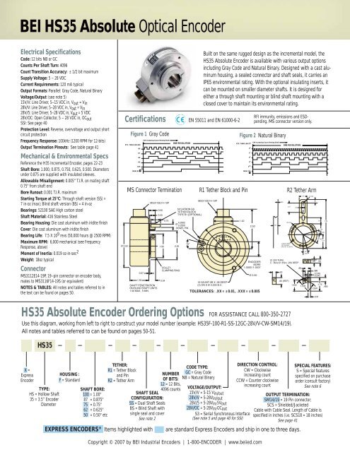
Figure 1 Gray Code<br />
ETC. THRU LSB (GO)<br />
G6<br />
G7<br />
G8<br />
G9<br />
G10<br />
MSB (G11)<br />
0.50<br />
0.45<br />
0.75<br />
Ø 3.50 1.90<br />
0.07<br />
CW Increasing Count Viewing Shaft<br />
1.50 0.54<br />
SHAFT PENETRATION<br />
ON BLIND SHAFT UNITS<br />
1.50 MAX, .5 MIN<br />
MS3112E14-19P<br />
2.25<br />
COLLET<br />
CLAMPING RING<br />
ONE REVOLUTION<br />
MS Connector Termination<br />
NYLATRON GS<br />
TETHER BLOCK<br />
TYPE R1 (OPTIONAL)<br />
0.2502<br />
Ø<br />
0.2500<br />
DOWEL PIN<br />
15°<br />
Built on the same rugged design as the incremental model, the<br />
<strong>HS35</strong> <strong>Absolute</strong> <strong>Encoder</strong> is available with various output options<br />
including Gray Code and Natural Binary. Designed with a cast aluminum<br />
housing, a sealed connector and shaft seals, it carries an<br />
IP65 environmental rating. With the optional insulating inserts, it<br />
can be mounted on smaller diameter shafts. It is designed for<br />
either a through shaft mounting or blind shaft mounting with a<br />
closed cover to maintain its environmental rating.<br />
EN 55011 and EN 61000-6-2<br />
MS3112E14-19P<br />
10-32UNF-2B X .38 DEEP<br />
(3) ON A Ø 3.000 B.C.<br />
ETC. THRU LSB (2 0 )<br />
R1 Tether Block and Pin<br />
1.42<br />
2 6<br />
2 7<br />
2 8<br />
2 9<br />
2 10<br />
MSB (2 11 )<br />
2.50<br />
ENCODER<br />
BORE<br />
1.0000 /1.0007<br />
Ø 3.50<br />
TOLERANCES: .XX = ± 0.01, .XXX = ± 0.005<br />
RFI immunity, emissions and ESDpending.<br />
MS connector version only.<br />
Figure 2 Natural Binary<br />
CW Increasing Count Viewing Shaft<br />
.58<br />
.020<br />
ONE REVOLUTION<br />
R2 Tether Arm<br />
1.10<br />
Ø 3.50<br />
.218 Ø THRU<br />
12 PLACES<br />
ON A Ø 3.00 B.C.<br />
.45<br />
Ø .203 THRU<br />
C Bore Ø .359 x .250 DEEP<br />
.50<br />
.83 (REF)<br />
1.450<br />
.96<br />
1.00<br />
1.75R<br />
15°<br />
(typ)<br />
R.225<br />
.50<br />
.45<br />
.81<br />
1.36<br />
15° (typ)<br />
30°(typ)<br />
1.75<br />
.388<br />
0.249<br />
0.247<br />
1.125R<br />
0.31<br />
.50<br />
6.25<br />
1.75<br />
.480<br />
<strong>HS35</strong> <strong>Absolute</strong> <strong>Encoder</strong> Ordering Options FOR ASSISTANCE CALL 800-350-2727<br />
Use this diagram, working from left to right to construct your model number (example: <strong>HS35</strong>F-100-R1-SS-12GC-28V/V-CW-SM14/19).<br />
All notes and tables referred to can be found on pages 50-51.<br />
<strong>HS35</strong><br />
X =<br />
Express<br />
<strong>Encoder</strong><br />
TYPE:<br />
HS = Hollow Shaft<br />
35 = 3.5” <strong>Encoder</strong><br />
Diameter<br />
HOUSING :<br />
F = Standard<br />
SHAFT BORE:<br />
100 = 1.00"<br />
87 = 0.875"<br />
75 = 0.75"<br />
62 = 0.625"<br />
50 = 0.50" etc<br />
TETHER:<br />
R1 = Tether Block<br />
and Pin<br />
R2 = Tether Arm<br />
SHAFT SEAL<br />
CONFIGURATION:<br />
SS = Dual Shaft Seals<br />
BS = Blind Shaft with<br />
single seal and cover<br />
See note 2<br />
NUMBER<br />
OF BITS:<br />
12 = 12 Bits,<br />
4096 counts<br />
CODE TYPE:<br />
GC = Gray Code<br />
NB = Natural Binary<br />
VOLTAGE/OUTPUT:<br />
15V/V = 5-15 Vin/out<br />
28V/V = 5-28Vin/out<br />
28V/5 = 5-28Vin/5Vout<br />
28V/OC = 5-28Vin/OCout<br />
S3 = Serial Synchronous Interface<br />
(See note 5 and page 40 for SSI)<br />
DIRECTION CONTROL:<br />
CW = Clockwise<br />
increasing count<br />
CCW = Counter clockwise<br />
increasing count<br />
Copyright © 2007 by <strong>BEI</strong> Industrial <strong>Encoder</strong>s | 1-800-ENCODER | www.beiied.com<br />
SPECIAL FEATURES:<br />
S = Special features<br />
specified on purchase<br />
order (consult factory)<br />
See note 6<br />
OUTPUT TERMINATION:<br />
SM14/19 = 19 Pin connector;<br />
SCS = Shielded/Jacketed<br />
Cable with Cable Seal. Length of Cable is<br />
specified in inches (i.e. SCS18 = 18 inches)<br />
See page 41<br />
EXPRESS ENCODERS ® Items highlighted with are standard Express <strong>Encoder</strong>s and ship in one to three days.
40<br />
<strong>BEI</strong> | Page <strong>Absolute</strong> Title <strong>Encoder</strong> Options<br />
Parallel <strong>Absolute</strong> Output<br />
The two most common types of absolute outputs are the Gray Code and the Natural<br />
Binary. Resolution for absolute encoders is expressed in “bits” where each successive<br />
bit increases the resolution by a factor of two. For example, 10 bits = 2 10 =<br />
1024 counts per revolution.<br />
Natural binary code (Figure 1) is constructed so that the code counts up using the<br />
natural sequence of binary counting, i.e. 000, 001, 010, 011, 100 . . etc. The drawback<br />
to using this code sequence is that at several count positions the code will<br />
have transitions on multiple bits simultaneously. Due to the normal variations<br />
caused by gate delays, line impedances, etc. the actual transitions will not occur<br />
simultaneously. Reading data during one of these times could result in an erroneous<br />
reading. This can be overcome by taking multiple readings.<br />
Gray code (Figure 2), by contrast, is designed to avoid the multiple transition problem<br />
entirely. It is specifically constructed so that only one bit will transition at a<br />
time. This ensures that state changes are much less ambiguous to the controller<br />
and is generally considered to be a more robust type of absolute code.<br />
Regardless of the code type, one of the characteristics of absolute encoders is that<br />
they can readily be used for any resolution up to and including their maximum resolution.<br />
For example, a 12 bit encoder can be used at only 8 bits by ignoring (or disconnecting)<br />
the four lowest significant bits (LSB). This enables an installation that<br />
uses multiple absolute encoders to use the same encoder throughout with each<br />
controller using only the bits that it needs.<br />
Figure 1 Natural Binary<br />
2 0<br />
(LSB)<br />
2 1<br />
2 2<br />
Figure 2 Gray Code<br />
G0<br />
(LSB)<br />
G1<br />
G2<br />
G3<br />
2 3 ETC. THRU G7 (MSB)<br />
ETC. THRU 2 7 (MSB)<br />
Ordering 8-Bit <strong>Absolute</strong>s<br />
For years, we produced encoders with a maximum resolution of 8 bits. Lots<br />
of those old 8 bit encoders are still around. We update them to newer 12 bit<br />
designs on a case-by-case basis. If you have an 8 bit encoder, here is how<br />
that model number was constructed: Direction of Rotation, Count, Code<br />
and Latch designators were inserted between Shaft Seal Configuration<br />
and Voltage/Output as shown below. To specify an equivalent encoder<br />
based on the 12 bit design, please call our Applications Specialists at 800-<br />
ENCODER (800-362-6337) or check our web site at www.beiied.com.<br />
Direction of Rotation: CCW or CW<br />
Count: 8<br />
Code: GC= Gray Code or NB= Natural Binary<br />
Latch: L= Latch or Blank=None<br />
Output Terminations: EM20=MS3102R20-29P or ED25=DB25P;<br />
SM18 = MS3102R18-1P; C18 = Cable, with length specified in<br />
inches. Specify ED25 for Line Driver Outputs.<br />
Example: H25E-F1-SS-CCW-8GC-28V/V-EM20<br />
(one possible encoder configuration with the 8-Bit <strong>Absolute</strong> Option.)<br />
Serial Synchronous Interface (SSI)<br />
SSI output provides effective synchronization in a closed-loop control system.<br />
A clock pulse train from a controller is used to clock out sensor data: one bit of position<br />
data is transmitted to the controller per one clock pulse received by the sensor.<br />
The use of a differential driver permits reliable transmission of data over long distances<br />
in environments that may be electrically noisy. The encoder utilizes a clock<br />
signal, provided by the user interface, to time the data transmission. Receiving electronics<br />
must include an appropriate receiver as well as line terminating resistors.<br />
Features<br />
• Synchronous transmission<br />
• Transmission lengths to 1000 feet<br />
• Accepts clock rates from 100 KHz to 1.8 MHz<br />
Data Transmission Sequence<br />
1. Output driver of the encoder is a MAX 491 transceiver in transmit mode.<br />
The recommended receiver is a MAX 491 transceiver in receive mode.<br />
2. Controller provides a series of pulses (or differential pulse pairs) on the CLOCK<br />
input lines.<br />
3. On the first HIGH-to-LOW CLOCK transition, the encoder latches its data at the<br />
current position and prepares to transmit.<br />
4. Controller reads data on the falling edge of the next 16 clock cycles.<br />
5. The first bit is a START bit and is always HIGH.<br />
6. Next come 12 data bits beginning with the most significant bit (MSB) and ending<br />
with the least significant bit (LSB). This is followed by three LOW pulses.<br />
7. After the DATA bits, the DATA line goes LOW and remains LOW for a minimum of<br />
30 microseconds between the end of the DATA bits and the beginning of the next<br />
CLOCK series.<br />
Interfacing Long Data Lines<br />
Cable impedance can create a transmission delay, in effect, shifting the phase relationship<br />
between the clock pulse and the data. If this phase shift exceeds 180°,<br />
then the wrong bit position will be sampled by the receiver. As a result, the maximum<br />
allowable clock frequency is a function of the cable length. For 24 AWG,<br />
stranded, 3 pair cable (<strong>BEI</strong> part number 37048-003 or equivalent) the group delay is<br />
1.36ns/ft. The table below shows the maximum transmission rate allowable as a<br />
function of cable length to ensure a phase shift of less than 90°.<br />
CLOCK, Maximum (kHz) = 92,000 / Cable Length (ft)CW<br />
Cable Length (ft) 50 100 200 300 500 1000<br />
Max Freq (kHz) 1800 900 500 300 200 100<br />
SSI Timing<br />
Ordering SSI<br />
HOW TO SPECIFY SSI OUTPUT IN THE ENCODER MODEL NUMBER:<br />
Use the designation, S3 between the Code Format designation<br />
and the Connector designation.<br />
Example: H25D-SS-12GC-S3-CW-SM18<br />
Copyright © 2007 by <strong>BEI</strong> Industrial <strong>Encoder</strong>s | 1-800-ENCODER | www.beiied.com
| 41<br />
<strong>Absolute</strong> <strong>Encoder</strong>s<br />
Single Turn <strong>Absolute</strong> <strong>Encoder</strong> Options<br />
The tables below are reference for pinouts, connections and operation of <strong>BEI</strong>’s single turn absolute encoders. These absolute options are<br />
available in a wide range of package styles with a variety of outputs. The applicability table below shows which combinations are currently<br />
available. As always, you can call us at 800-350-ASAP (2727) for immediate applications assistance should you have any questions.<br />
Output Code and Terminations (12 & 13 Bit)<br />
PARALLEL CODE<br />
Binary<br />
Natural Coded<br />
Gray Code Binary Decimal<br />
12 Bit 13 Bit 12 Bit 13 Bit<br />
MSB G 11 G 12 2 11 2 12 A 0<br />
G 10 G 11 2 10 2 11 B 0<br />
G 9 G 10 2 9 2 10 C0<br />
G 8 G 9 2 8 2 9 D 0<br />
G 7 G 8 2 7 2 8 A 1<br />
G 6 G 7 2 6 2 7 B 1<br />
G 5 G 6 2 5 2 6 C 1<br />
G 4 G 5 2 4 2 5 D 1<br />
G 3 G 4 2 3 2 4 A 2<br />
G 2 G 3 2 2 2 3 B 2<br />
G 1 G 2 2 1 2 2 C 2<br />
LSB 12 G 0 G 1 2 0 2 1 D 2<br />
LSB 13 G 0 2 0 A 3<br />
0V (CIRCUIT COMMON) 1 B3<br />
DIRECTION CONTROL<br />
CASE GROUND<br />
0 V (CIRCUIT COMMON)<br />
LATCH CONTROL<br />
+V (SUPPLY VOLTAGE)<br />
SHIELD DRAIN<br />
1<br />
Pin P is available for a tri-state option<br />
TERMINATION TYPE<br />
Term<br />
Board<br />
Cable Conn H38 & H40<br />
WHT/BLK A 1<br />
WHT/BRN B 2<br />
WHT/RED C 3<br />
WHT/ORN D 4<br />
WHT/YEL E 5<br />
WHT/GRN F 6<br />
WHT/BLU G 7<br />
WHT/VIO H 8<br />
WHT/GRY J 9<br />
WHT K 10<br />
GRY/BLK L 11<br />
GRY/BRN M 12<br />
GRY/RED N 13<br />
GRY/ORN P<br />
ORN R 18<br />
GRN S 16<br />
BLK T 15<br />
YEL U 17<br />
RED V 14<br />
BARE —<br />
Output Applicability Table<br />
12 BITS 13 BITS 14/15 12x12 S3 S1 A1 A2<br />
PARALLEL PARALLEL BITS BITS SSI RS422 4–20mA 0–10 V<br />
H25 • • • • • •<br />
H25X • •<br />
<strong>HS35</strong> • •<br />
H38 • • • • • • •<br />
H40 • • • • • • •<br />
HMT25 • • • •<br />
Direction Control: Standard is CW increasing when viewed from the shaft end.<br />
Pin R is normally HI (or N/C) and is pulled up internally to +V. To reverse the count<br />
direction, Pin R must be pulled LO (COMMON ).<br />
Latch control: <strong>Encoder</strong> outputs are active and provide continuous parallel position<br />
information when Pin U is HI (or N/C). Pin U is pulled up internally to +V. When<br />
Pin U is LO (COMMON) the encoder outputs are latched at the logic state that is present<br />
when the latch is applied and will stay latched until Pin U is no longer grounded.<br />
Parallel Code (14 & 15 Bit) 2<br />
M14/19<br />
Gray Code Natural Binary Connector<br />
14 BIT 15 Bit 14 BIT 15 Bit<br />
MSB G 13 G 14 2 13 2 14 A<br />
G 12 G 13 2 12 2 13 B<br />
G 11 G 12 2 11 2 12 C<br />
G 10 G 11 2 10 2 11 D<br />
G 9 G 10 2 9 2 10 E<br />
G 8 G 9 2 8 2 9 F<br />
G 7 G 8 2 7 2 8 G<br />
G 6 G 7 2 6 2 7 H<br />
G 5 G 6 2 5 2 6 J<br />
G 4 G 5 2 4 2 5 K<br />
G 3 G 4 2 3 2 4 L<br />
G 2 G 3 2 2 2 3 M<br />
G 1 G 2 2 1 2 2 N<br />
LSB14 G 0 G 1 2 0 2 1 P<br />
LSB15 DIR G 0 DIR 2 0 R<br />
CONTROL<br />
CONTROL<br />
CASE GROUND<br />
S<br />
OV (CIRCUIT COMMON)<br />
T<br />
LATCH DIR/LATCH LATCH DIR/LATCH U<br />
+V (SUPPLY +V (SUPPLY +V (SUPPLY +V (SUPPLY<br />
VOLTAGE) VOLTAGE) VOLTAGE) VOLTAGE)<br />
V<br />
2<br />
Units Manufactured before April 2007 are LSB Justified.<br />
SSI Output Termination Table<br />
M18 M14/19 CABLE TERM. BOARD<br />
CONN CONN CONN H38 H40<br />
DATA + A A YEL 4 1<br />
DATA- H B WHT/YEL 7 7<br />
CLOCK+ B C BLU 5 2<br />
CLOCK- I D WHT/BLU 8 8<br />
DIR CONTROL C R ORN 6 3<br />
CASE GROUND G S GRN 1 6<br />
CIRCUIT COMMON F T BLK 2 5<br />
+V SUPPLY VOLTAGE D V RED 3 4<br />
SHIELD DRAIN — — BARE — —<br />
Dir/Latch on 15-Bit <strong>Encoder</strong>s: Due to a limited number of connector pins, either<br />
direction control or latch is available on pin U.<br />
M18 Connector is a MS3102R18-1P, 10-pin connector on the encoder body and mates<br />
to an MS3106F18-1S connector or can be used with a standard cable/connector<br />
assembly, <strong>BEI</strong> P/N 924-31186-18XX (Where X = 10, 20 or 30 for a 10, 20, or 30 foot<br />
length). This is the preferred connector for SSI output.<br />
M14/19 Connector is a MS3112E14-19P, 19-pin connector on the encoder body and<br />
mates to an MS3116F14-19S or equivalent.<br />
Copyright © 2007 by <strong>BEI</strong> Industrial <strong>Encoder</strong>s | 1-800-ENCODER | www.beiied.com