new way of accuracy improvement for the pneumatic ... - imeko
new way of accuracy improvement for the pneumatic ... - imeko
new way of accuracy improvement for the pneumatic ... - imeko

Create successful ePaper yourself
Turn your PDF publications into a flip-book with our unique Google optimized e-Paper software.
Proceedings, XVII IMEKO World Congress, June 22 – 27, 2003, Dubrovnik, Croatia<br />
Proceedings, XVII IMEKO World Congress, June 22 – 27, 2003, Dubrovnik, Croatia<br />
TC1<br />
TC16<br />
XVII IMEKO World Congress<br />
Metrology in <strong>the</strong> 3 rd Millennium<br />
June 22−27, 2003, Dubrovnik, Croatia<br />
NEW WAY OF ACCURACY IMPROVEMENT FOR THE PNEUMATIC<br />
DEADWEIGHT TESTER V1600<br />
M. Bryant 1 , N. Moisoi 1 and S.M.Kesselman 2<br />
1 Pressurements Limited, Dunstable, UK<br />
2 Pressure laboratory, Russian Research Institute <strong>for</strong> Metrological Service (VNIIMS), Moscow, Russia<br />
Abstract - The V1600 is a compact portable pressure<br />
balance suitable <strong>for</strong> applications where a large number <strong>of</strong><br />
high <strong>accuracy</strong> calibrations in ranges from 20 Pa up to 16<br />
kPa, need to be per<strong>for</strong>med on a daily basis.<br />
Calibrations per<strong>for</strong>med at VNIIMS, LNE, MIKE,<br />
NIST and PTB have shown <strong>the</strong> uncertainty <strong>of</strong> <strong>the</strong> V1600 is<br />
less than 0.1 Pa below 500 Pa and 0.02% <strong>of</strong> reading from<br />
500 Pa to 16 kPa.<br />
An important part <strong>of</strong> <strong>the</strong> uncertainty <strong>of</strong> <strong>the</strong> instrument<br />
within <strong>the</strong> range 500 Pa to 16 kPa has been caused by a<br />
methodical error <strong>of</strong> <strong>the</strong> procedure applied to its calibration<br />
until now.<br />
This paper presents <strong>the</strong> original manner <strong>of</strong> detection<br />
and elimination <strong>of</strong> <strong>the</strong> above-mentioned systematic error.<br />
This <strong>new</strong> calibration approach is based on <strong>the</strong> equality<br />
<strong>of</strong> Eulerian criterion <strong>of</strong> <strong>the</strong> actual device with its<br />
ma<strong>the</strong>matical model and allows an increase <strong>of</strong> <strong>the</strong><br />
calibration <strong>accuracy</strong> with approximately 1,5 – 2 times <strong>for</strong><br />
pressures above 500 Pa.<br />
Key words: deadweight tester, <strong>accuracy</strong>, calibration.<br />
Introduction<br />
A full description <strong>of</strong> V1600 is given in [1]. The main<br />
instrument component is a transducer, which trans<strong>for</strong>ms <strong>the</strong><br />
gravitational <strong>for</strong>ce Mg <strong>of</strong> <strong>the</strong> piston and loads into a<br />
<strong>pneumatic</strong> pressure P using a system consisting in a variable<br />
throttle (piston-nozzle assembly) and a fixed throttle (<strong>the</strong><br />
gap between nozzle and nozzle-body).<br />
The output pressure <strong>of</strong> <strong>the</strong> transducer is applied to <strong>the</strong><br />
inlet <strong>of</strong> a two-cascade regulator, which has <strong>the</strong> role to<br />
support <strong>the</strong> piston with high <strong>accuracy</strong> at a particular height<br />
above <strong>the</strong> edge <strong>of</strong> nozzle.<br />
As <strong>the</strong> air flows through <strong>the</strong> gap between <strong>the</strong> piston<br />
cone and <strong>the</strong> nozzle, a reactive feedback <strong>for</strong>ce R is<br />
generated.<br />
There<strong>for</strong>e <strong>the</strong> measurement equation <strong>of</strong> V1600<br />
pressure balance can be written as follows:<br />
P = Mg (1 - ρ a /ρ m )/A 0 + R/ A 0, (1)<br />
where: (1 - ρ a /ρ m ) – air buoyancy correction factor,<br />
R = G (υCosβ - υ 1 )/ A 0 ,<br />
A 0 - geometrical area <strong>of</strong> <strong>the</strong> nozzle’s edge,<br />
G - mass flow rate,<br />
υ and - υ 1 velocity <strong>of</strong> <strong>the</strong> gas exhausting from <strong>the</strong><br />
nozzle-piston gap and respective velocity <strong>of</strong> <strong>the</strong> gas<br />
in <strong>the</strong> space under <strong>the</strong> piston,<br />
h – effective gap between <strong>the</strong> piston and nozzle in a<br />
perpendicular direction <strong>of</strong> <strong>the</strong> velocity υ,<br />
2β - angle at <strong>the</strong> peak <strong>of</strong> <strong>the</strong> piston cone.<br />
The most convenient <strong>way</strong> to use <strong>the</strong> V1600 pressure<br />
balance is to know its main parameter, <strong>the</strong> effective area:<br />
A = A 0 (1 - q), (2)<br />
where: q = G (υCosβ - υ 1 ) /Mg which can be re-written:<br />
q = (4hCosβ)/(R 0 Eu), as υ 1
Proceedings, XVII IMEKO World Congress, June 22 – 27, 2003, Dubrovnik, Croatia<br />
Proceedings, XVII IMEKO World Congress, June 22 – 27, 2003, Dubrovnik, Croatia<br />
TC1<br />
TC16<br />
The effective area <strong>of</strong> V1600 can be determined by<br />
direct comparison with a pressure standard <strong>of</strong> a higher<br />
<strong>accuracy</strong>.<br />
The problem arises when it is necessary to calibrate or<br />
to test pressure instruments with an uncertainty less than<br />
(0,05 – 0,1) Pa in <strong>the</strong> range below 3000 Pa, where very <strong>of</strong>ten<br />
it is not possible to determine <strong>the</strong> effective area by direct<br />
comparison.<br />
There<strong>for</strong>e <strong>the</strong> effective area <strong>of</strong> each V1600 is<br />
determined accordingly with <strong>the</strong> original method <strong>of</strong><br />
calibration described in [2]. This method is based on<br />
definition <strong>of</strong> effective area A c , at a pressure P c ,<br />
corresponding to <strong>the</strong> mass M c (including piston, carrier and<br />
weights), within its range, which is accessible to <strong>the</strong><br />
available standard, <strong>for</strong> example: 3, 6 or 16 kPa.<br />
The equation <strong>of</strong> calibration is given by:<br />
The main component <strong>of</strong> V1600 is a divider <strong>of</strong> <strong>the</strong><br />
supply pressure P s acting on its inlet. The dependence<br />
between <strong>the</strong>oretical output pressure P <strong>of</strong> <strong>the</strong> divider and<br />
pressure P s on its inlet can be given by:<br />
P s = θ P, (5)<br />
where: θ -<strong>the</strong> relationship <strong>of</strong> throttles conductivity.<br />
The value <strong>of</strong> coefficient θ depends on <strong>the</strong> modes <strong>of</strong> <strong>the</strong><br />
gas flow through <strong>the</strong> throttles and can be determined from<br />
equality <strong>of</strong> <strong>the</strong> flow rate through <strong>the</strong> throttles.<br />
The fixed throttle <strong>of</strong> <strong>the</strong> divider is manufactured as an<br />
annual gap between <strong>the</strong> nozzle and <strong>the</strong> nozzle-body with <strong>the</strong><br />
nominal value <strong>of</strong> <strong>the</strong> width H = (0,15 – 0,17) mm and <strong>the</strong><br />
length L =10 mm, Fig. 1.<br />
A j = A c [1 – q c (q c /q j – 1)] (4)<br />
where: q c = G c υ c Cosβ/M c g,<br />
υ c = {[2kRT/(k-1)]*[1 – (p a /p) (k-1)/k ]} 1/2 or<br />
υ c =(2P/ρ) 1/2 as in <strong>the</strong> range from 0,02 up to 16 kPa<br />
<strong>the</strong> compressibility <strong>of</strong> <strong>the</strong> air can be neglected,<br />
q j /q c = {(p j /p c ) 1/k [(P sj - P j )/(P sc - P c )]*(M c M j )} 1/2<br />
p j and p c – absolute pressure corresponding to <strong>the</strong><br />
pressure P c ∼M c g/A 0 and P j ∼ M j g/ A 0 , P sj , as long as<br />
<strong>the</strong> real value <strong>of</strong> A 0 is unknown,<br />
R - universal gas constant,<br />
T - absolute temperature,<br />
k – adiabatic index.<br />
The analysis <strong>of</strong> <strong>the</strong> calibration results from several<br />
instruments has shown that <strong>the</strong> relative <strong>accuracy</strong>, due to<br />
calibration method, begins to increase at 700 Pa and reaches<br />
up to 0,009 % at 16 kPa.<br />
The purpose <strong>of</strong> this paper is to present <strong>the</strong> original<br />
manner <strong>of</strong> detection and elimination <strong>of</strong> above mentioned<br />
systematic error.<br />
New <strong>way</strong> <strong>of</strong> <strong>accuracy</strong> <strong>improvement</strong> <strong>for</strong> <strong>the</strong> V1600<br />
This behavior <strong>of</strong> <strong>the</strong> calibration results can to be<br />
explained by both local and travelling losses, which<br />
inevitably arise at measuring pressure P sj at its origin place.<br />
The essential losses are created by <strong>the</strong> connector found<br />
between <strong>the</strong> manometer <strong>for</strong> measurings Ps and <strong>the</strong> pipeline.<br />
The inlet hole <strong>of</strong> <strong>the</strong> connector should be<br />
perpendicularly to an interior wall <strong>of</strong> <strong>the</strong> pipeline channel.<br />
If <strong>the</strong> inlet hole <strong>of</strong> <strong>the</strong> connection has a very small<br />
diameter (a few tenths <strong>of</strong> a millimetre), <strong>the</strong> gas flow will not<br />
generate any false pressure readings.<br />
In o<strong>the</strong>r case <strong>the</strong> hole causes some deflections <strong>of</strong> <strong>the</strong><br />
stream. There<strong>for</strong>e <strong>the</strong> real static pressure P′ differs from <strong>the</strong><br />
measured pressure P s : P′ = P s ± χρυ′ 2 /2, where: ρυ′ 2 /2 – <strong>the</strong><br />
dynamic pressure due by medial velocity υ′ in <strong>the</strong> pipe<br />
channel and χ - is a coefficient, depending on <strong>the</strong> diameter<br />
<strong>of</strong> <strong>the</strong> hole and <strong>of</strong> its shape.<br />
At χ >0 <strong>the</strong> gas stream can create small refraction or<br />
contrariwise back pressure when χ
Proceedings, XVII IMEKO World Congress, June 22 – 27, 2003, Dubrovnik, Croatia<br />
Proceedings, XVII IMEKO World Congress, June 22 – 27, 2003, Dubrovnik, Croatia<br />
TC1<br />
TC16<br />
ξ in and ξ out - coefficient <strong>of</strong> irreversible losses at <strong>the</strong><br />
inlet <strong>of</strong> <strong>the</strong> throttle and respectively at <strong>the</strong> output <strong>of</strong><br />
<strong>the</strong> throttle,<br />
ϑ- coefficient <strong>of</strong> <strong>the</strong> kinetic energy, as <strong>the</strong> fixed<br />
throttle is between <strong>the</strong> two chambers (<strong>the</strong> space<br />
be<strong>for</strong>e and after throttle) which have a considerable<br />
bigger size in comparison with <strong>the</strong> throttle,<br />
K′ = 0,16 - irreversible losses on an initial site <strong>of</strong><br />
fixed throttle [4].<br />
The left term <strong>of</strong> <strong>the</strong> (6) represents a dimensionless<br />
value and it is similar with Eu criterion (Euler number). The<br />
right term <strong>of</strong> (6) is practically an extension <strong>of</strong> a similar<br />
criterion <strong>for</strong> <strong>the</strong> given physical quantities, as it is equal to<br />
<strong>the</strong> ratio <strong>of</strong> <strong>the</strong> two criteria: parametric and Reynolds.<br />
The mode <strong>of</strong> a motion through a variable throttle is<br />
al<strong>way</strong>s turbulent due to <strong>the</strong> piston’s oscillations, as it is selfbalanced<br />
and self-centered continuously.<br />
Proceed from above-mentioned and take into account,<br />
that in a steady stated mode <strong>the</strong> mean velocity in <strong>the</strong> channel<br />
<strong>of</strong> <strong>the</strong> fixed throttle is related to <strong>the</strong> mean velocity <strong>of</strong><br />
outflow from <strong>the</strong> nozzle by <strong>the</strong> equation:<br />
υ 2 = υ(µh g /H), (7)<br />
where: υ = (2P/ρ) 1/2 - <strong>the</strong>oretical velocity <strong>of</strong> <strong>the</strong><br />
outflow from <strong>the</strong> nuzzle,<br />
µh g = h - effective gap between <strong>the</strong> piston and nozzle<br />
in a perpendicular direction to <strong>the</strong> velocity υ,<br />
µ = εϕ - coefficient <strong>of</strong> outflow <strong>of</strong> <strong>the</strong> nozzle,<br />
ε - gas compressibility coefficient ,<br />
ϕ = 1/(α 0 + ζ) 1/2 –velocity coefficient,<br />
α 0 – correction due by <strong>the</strong> velocity non-uni<strong>for</strong>mity<br />
on <strong>the</strong> cross section <strong>of</strong> <strong>the</strong> channel,<br />
ζ - <strong>the</strong> nozzle flow resistance,<br />
h g – geometrical gap between <strong>the</strong> piston and nuzzle<br />
in a perpendicular direction to velocity υ,<br />
<strong>the</strong> dependence between <strong>the</strong> supply pressure P s and <strong>the</strong><br />
output pressure P <strong>of</strong> <strong>the</strong> V1600 divider, as a similarity<br />
criterion, can be given by:<br />
(Ps - P)/P =(µh/H) 2 *[λ (L/2H) + ξ in + ξ out + ϑ + K′] (8)<br />
or<br />
P s = P[1 + (µh/H) 2 * (A + B)]<br />
where: A = 24(πDν/Q)*(L/H)<br />
B = (ξ in + ξ out + ϑ + K′).<br />
(8a)<br />
At B =0 and when <strong>the</strong> compressibility <strong>of</strong> gas can be<br />
neglected, <strong>the</strong> dependency between <strong>the</strong> pressure drop and<br />
<strong>the</strong> flow rate is given by Poiseuille’s <strong>for</strong>mula, which is<br />
deduced from <strong>the</strong> total Poiseuille's law:<br />
G = πDH 3 ∆P/(12νL 1 ), (9)<br />
where: ∆P – <strong>the</strong> friction losses when it is a laminar flow in<br />
<strong>the</strong> throttle,<br />
L 1
Proceedings, XVII IMEKO World Congress, June 22 – 27, 2003, Dubrovnik, Croatia<br />
Proceedings, XVII IMEKO World Congress, June 22 – 27, 2003, Dubrovnik, Croatia<br />
TC1<br />
TC16<br />
The ratio <strong>of</strong> <strong>the</strong> effective arias <strong>of</strong><br />
throttles, a = h/H<br />
Fig. 2. V1600 s/n 359. Dependence <strong>of</strong> <strong>the</strong> ratio α<br />
on a Reynolds number <strong>of</strong> incident flow<br />
If an ideal and an actual device have <strong>the</strong> same value <strong>of</strong><br />
<strong>the</strong> Euler number, <strong>the</strong>y are dynamically similar. The<br />
equality <strong>of</strong> Euler number in dynamically similar systems<br />
ensures <strong>the</strong> similarity <strong>of</strong> <strong>the</strong> pressure <strong>for</strong>ces.<br />
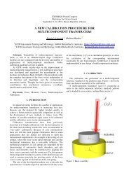
The calibration procedure states <strong>the</strong> necessity <strong>of</strong><br />
measuring <strong>the</strong> pressure Ps with respect to <strong>the</strong> relevant values<br />
<strong>of</strong> <strong>the</strong> output pressure P. From <strong>the</strong>se values <strong>the</strong> coefficient θ<br />
<strong>of</strong> <strong>the</strong> actual instrument can be determined by linear<br />
interpolation: Ps = (aP + b), as is shown graphically in<br />
Fig.3. Then, varying <strong>the</strong> coefficient α <strong>for</strong> <strong>the</strong> (3), using <strong>the</strong><br />
special s<strong>of</strong>tware, P s is obtained (5) <strong>of</strong> an ideal transducer<br />
with <strong>the</strong> same value <strong>of</strong> <strong>the</strong> slope: Psid = (aP + bid).<br />
Supply pressure Ps, Pa<br />
1.2<br />
1.0<br />
0.8<br />
0.6<br />
0.4<br />
0.2<br />
0.0<br />
16000<br />
12000<br />
8000<br />
4000<br />
a=(h/H)des<br />
a=( h/H)act<br />
0 25 50 75 100 125 150 175 200 225<br />
Reynolds number <strong>of</strong> <strong>the</strong> incident flow<br />
y = 1.0179x + 29.376<br />
R 2 = 1<br />
0<br />
0 4000 8000 12000 16000<br />
Output pressure P, Pa<br />
Fig.3. V1600 s/n 359. Dependence <strong>of</strong> actual supply<br />
pressure P s <strong>of</strong> divider on output pressure P<br />
The equation (5) written <strong>for</strong> <strong>the</strong> actual and <strong>for</strong> <strong>the</strong> ideal<br />
device is shown in tab. 1 (<strong>the</strong> measurements have been<br />
per<strong>for</strong>med <strong>for</strong> <strong>the</strong> V1600, S/N: 359):<br />
Table1<br />
V1600 s/n 359. Real device V1600 s/n 359. Ideal device<br />
P s = 1,0179 P + 29,376 P s = 1,0179 P + 28,967<br />
where: P s = 29,376 and P s = 28,967 – <strong>the</strong> pressure difference<br />
on <strong>the</strong> fixed throttle when is no piston on <strong>the</strong> nozzle, in <strong>the</strong><br />
real and respectively ideal case. The actual value measured<br />
by calibrator was P s = 28 Pa.<br />
The equality <strong>of</strong> <strong>the</strong> angular coefficients means <strong>the</strong> pistons <strong>of</strong><br />
<strong>the</strong> ideal and <strong>the</strong> actual device have identical displacement<br />
<strong>of</strong> <strong>the</strong> pistons with <strong>the</strong> change in pressure. Hence, <strong>the</strong><br />
requirement <strong>of</strong> geometrical similarity is respected.<br />
In order to calculate <strong>the</strong> ideal values <strong>of</strong> P s. , <strong>the</strong><br />
s<strong>of</strong>tware is using (3) and it is combining <strong>the</strong> ideal and <strong>the</strong><br />
actual characteristics <strong>of</strong> <strong>the</strong> divider.<br />
In <strong>the</strong> tab. 2 a discrepancy ∆P s = (P sact – P sid ) between<br />
<strong>the</strong> ideal and <strong>the</strong> experimental values <strong>of</strong> <strong>the</strong> supply pressure<br />
P s <strong>of</strong> <strong>the</strong> V1600 s/n 359 are shown:<br />
Table 2<br />
P n , Pa 20 100 120 200 700<br />
∆P s , Pa 0,1 -0,5 0,1 -0,6 0,3<br />
Continuation <strong>of</strong> Table 2<br />
P n , Pa 1000 3000 6000 10000 16000<br />
∆P s , Pa 4,3 21,1 21,9 10,7 -17,9<br />
The actual value <strong>of</strong> <strong>the</strong> supply pressure P s was<br />
measured by Druck calibrator DPI 145. The upper<br />
measuring limits <strong>of</strong> <strong>the</strong> two sensors are 0,5 bar and 1 bar<br />
and <strong>the</strong> uncertainty <strong>of</strong> <strong>the</strong> measured pressure (at 2 sigma<br />
level, determined by calibration) was less than 5 Pa.<br />
Equation (5) <strong>for</strong> <strong>the</strong> actual device s/n 359 and <strong>for</strong> its<br />
ma<strong>the</strong>matical model (10) is shown in tab.3:<br />
Table 3<br />
V1600 s/n 359. Real device V1600 s/n 359. Ideal device<br />
P s = 1,0179 P + 29,376 P s = 1,0179 P + 39,892<br />
As it is visible from table 3 at an output pressure Р=0<br />
Pa, <strong>the</strong> pressure drop on <strong>the</strong> fixed throttle obtained by using<br />
<strong>the</strong> frictional model (10) is with 10,5 Pa more than<br />
measured.<br />
For example <strong>the</strong> discrepancy ∆P s = (P sac – P sid )<br />
between <strong>the</strong> experimental values <strong>of</strong> supply pressure P s <strong>of</strong> <strong>the</strong><br />
V1600 s/n 359 and <strong>the</strong> values given by its ma<strong>the</strong>matical<br />
model (10) are shown in tab.4:<br />
Table 4<br />
P n , Pa 20 100 120 200 700<br />
∆P s , Pa 16,4 3,2 1,7 -5,5 -26,0<br />
Continuation <strong>of</strong> Table 4<br />
P n , Pa 1000 3000 6000 10000 16000<br />
∆P s , Pa -29,0 -29,5 -24,1 -11,6 8,0<br />
Dependence <strong>of</strong> design Euler’s criterion <strong>of</strong> two<br />
surveyed ma<strong>the</strong>matical models on actual Euler’s criterion <strong>of</strong><br />
V1600 s/n 359 is shown on Fig. 4.
Proceedings, XVII IMEKO World Congress, June 22 – 27, 2003, Dubrovnik, Croatia<br />
Proceedings, XVII IMEKO World Congress, June 22 – 27, 2003, Dubrovnik, Croatia<br />
TC1<br />
TC16<br />
Design Euler's criterion<br />
1.4<br />
1.2<br />
1.0<br />
0.8<br />
0.6<br />
0.4<br />
0.2<br />
Eudes<br />
EudesLam<br />
0.0<br />
0.0 0.2 0.4 0.6 0.8 1.0 1.2 1.4<br />
Actual Euler's criterion<br />
Fig. 4. V1600 s/n 359. The design Euler’s criterion<br />
versus actual Euler’s criterion<br />
The graph presented in Fig. 4 suggests clearly that <strong>the</strong><br />
gas streams, in <strong>the</strong> actual device and in its model based on<br />
Poiseuille’s law, are dynamically similar. The ma<strong>the</strong>matical<br />
model provide almost <strong>the</strong> same results with <strong>the</strong> real device<br />
when <strong>the</strong> losses <strong>of</strong> pressure are proportional to a quadrate <strong>of</strong><br />
velocity.<br />
In tab. 5, <strong>the</strong> values <strong>of</strong> <strong>the</strong> experimental and <strong>the</strong> design<br />
model (8) <strong>of</strong> Euler’s criterion <strong>for</strong> V1600 s/n 359 are<br />
presented:<br />
Table 5<br />
P n , Pa 20 100 120 200 700<br />
Eudes 1,39 0,30 0,25 0,16 0,06<br />
Euact 1,40 0,29 0,25 0,16 0,06<br />
Continuation <strong>of</strong> Table 5<br />
P n , Pa 1000 3000 6000 10000 16000<br />
Eudes 0,05 0,03 0,02 0,02 0,02<br />
Euact 0,05 0,04 0,03 0,02 0,02<br />
The V1600 s/n 359 was calibrated by comparison with<br />
<strong>the</strong> P7000 Pressurements standard (total uncertainty less<br />
<strong>the</strong>n 50 ppm,) at <strong>the</strong> pressure P c = 6 kPa. In <strong>the</strong> tab. 6 <strong>the</strong><br />
mean value <strong>of</strong> <strong>the</strong> difference between effective area A<br />
calculated using <strong>the</strong> old and <strong>the</strong> <strong>new</strong> method <strong>of</strong> calibration,<br />
from <strong>the</strong> values A, obtained by direct comparison <strong>of</strong> <strong>the</strong><br />
V1600 with <strong>the</strong> P7000 standard are shown in tab.6:<br />
Table 6<br />
(A old – A <strong>new</strong> )/ A <strong>new</strong> , %<br />
P n , kPa Old method New method σ, %<br />
8 0,006 0,003 0,0003<br />
10 0,007 0,002 0,0006<br />
12 0,008 0,001 0,0006<br />
14 0,007 -0,002 0,0005<br />
16 0,009 -0,002 0,0006<br />
where: σ - standard deviation <strong>of</strong> <strong>the</strong> mean.<br />
The data presented in <strong>the</strong> tab.6 was confirmed by <strong>the</strong><br />
calibration results <strong>of</strong> many V1600 instruments, which have<br />
been carried out at Pressurements and VNIIMS.<br />
The V1600 is rapidly gaining recognition and<br />
acceptation as a standard <strong>for</strong> low-pressure calibrations at<br />
various levels <strong>of</strong> <strong>the</strong> calibration hierarchy.<br />
Conclusion<br />
An important part <strong>of</strong> <strong>the</strong> calibration uncertainty <strong>of</strong> <strong>the</strong><br />
effective area <strong>of</strong> <strong>the</strong> V1600 has been caused by a methodical<br />
error <strong>of</strong> measuring <strong>the</strong> pressure difference on <strong>the</strong> fixed<br />
throttle <strong>of</strong> <strong>the</strong> <strong>pneumatic</strong> transducer.<br />
The <strong>new</strong> calibration approach is based on <strong>the</strong> equality<br />
<strong>of</strong> <strong>the</strong> Eulerian criterion <strong>of</strong> <strong>the</strong> actual device and its<br />
ma<strong>the</strong>matical model <strong>for</strong> a quadratic dependence between <strong>the</strong><br />
pressure difference on <strong>the</strong> fixed throttle and flow rate.<br />
This <strong>new</strong> approach is permitting <strong>the</strong> use <strong>of</strong> <strong>the</strong> supply<br />
pressure provided by <strong>the</strong> ma<strong>the</strong>matical model <strong>for</strong> <strong>the</strong><br />
calibration <strong>of</strong> V1600’s effective area.<br />
This method allows an essential increase <strong>of</strong> <strong>the</strong><br />
calibration <strong>accuracy</strong> <strong>of</strong> V1600 instrument within <strong>the</strong> range 3<br />
kPa to 16 kPa.<br />
REFERENCES<br />
[1] “Users handbook. Portable, low pressure <strong>pneumatic</strong> deadweight<br />
testers”, Pressurements Ltd, Dunstable, Bed<strong>for</strong>dshire,<br />
England.<br />
[2] S. M. Kesselman, “The calibrator <strong>of</strong> pressure "Vozdukh". A<br />
Path<strong>way</strong> to <strong>accuracy</strong>”, Legal and applied metrology, no. 4,<br />
pp.25-28, April 1993.<br />
[3] V. N .Constantinescu, “Gas lubrication”, Machine building,<br />
pp.45-47, Moscow,1968.<br />
[4] A. I. Bogomolov, K. A Mikhailov, “Hydraulics’, Stroyizdat,<br />
pp.97-98, Moscow, 1972<br />
Authors:<br />
M. Bryant<br />
Commercial Director, GE Druck Holdings p.l.c Fir Tree<br />
Lane Groby Leicester LE6 0FH<br />
phone: 0116 231 7100<br />
fax: 0116 287 1460<br />
e-mail:bryantm@druck.com<br />
N. Moisoi<br />
Head <strong>of</strong> Laboratory, Pressurements Limited,<br />
Unit 22, Apex Business Centre, Boscombe<br />
Road, Dunstable Beds, LU5 4SB, England,<br />
phone: +44 (0) 1582 474535<br />
fax: +44 (0) 1582 601185<br />
e-mail: moisoin@pressurements.com<br />
S. M. Kesselman<br />
Head <strong>of</strong> Pressure Laboratory, Russian Research<br />
Institute <strong>for</strong> metrological Service (VNIIMS), 46<br />
Ozernaya, G-361, Moscow, 119361, Russia,<br />
phone: (095) 422-0636<br />
fax (095) 437-5666<br />
e-mail: kesstella@cnt.ru