Preparing Infrastructure for 10 Gigabit Ethernet Applications - Belden
Preparing Infrastructure for 10 Gigabit Ethernet Applications - Belden
Preparing Infrastructure for 10 Gigabit Ethernet Applications - Belden
Create successful ePaper yourself
Turn your PDF publications into a flip-book with our unique Google optimized e-Paper software.
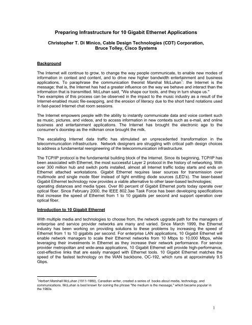
<strong>Preparing</strong> <strong>Infrastructure</strong> <strong>for</strong> <strong>10</strong> <strong>Gigabit</strong> <strong>Ethernet</strong> <strong>Applications</strong><br />
Christopher T. Di Minico, Cable Design Technologies (CDT) Corporation,<br />
Bruce Tolley, Cisco Systems<br />
Background<br />
The Internet will continue to grow, to change the way people communicate, to enable new modes of<br />
in<strong>for</strong>mation in context and content, and to drive new higher bandwidth entertainment and business<br />
applications. To paraphrase the communication theorist Marshal McLuhan 1 : the Internet is the<br />
message; that is, the Internet has had a greater influence on the way we behave and interact than the<br />
in<strong>for</strong>mation that is transmitted. McLuhan said, "We shape our tools, and they in turn shape us."<br />
Two examples of this process can be observed in the impact to the music industry as a result of the<br />
Internet-enabled music file-swapping, and the erosion of literacy due to the short hand notations used<br />
in fast-paced Internet chat room sessions.<br />
The Internet empowers people with the ability to instantly communicate data and voice content such<br />
as music, pictures, and videos, and to access in<strong>for</strong>mation in new contexts such as e-mail, and online<br />
business and entertainment applications. The Internet has brought the electronic age to the<br />
consumer’s doorstep as the milkman once brought the milk.<br />
The escalating Internet data traffic has stimulated an unprecedented trans<strong>for</strong>mation in the<br />
telecommunication infrastructure. Network designers are struggling with critical path design choices<br />
to address a fundamental reengineering of the telecommunication infrastructure.<br />
The TCP/IP protocol is the fundamental building block of the Internet. Since its beginning, TCP/IP has<br />
been associated with <strong>Ethernet</strong>, the most successful Layer 2 protocol in the history of networking. With<br />
over 300 million hub and switch ports installed, almost all Internet traffic today starts and ends on<br />
<strong>Ethernet</strong> attached workstations. <strong>Gigabit</strong> <strong>Ethernet</strong> requires laser sources <strong>for</strong> transmission over<br />
multimode and single mode fiber instead of light emitting diode sources (LED’s). The laser-based<br />
<strong>Gigabit</strong> <strong>Ethernet</strong> technology now provides a viable alternative to other laser-based technologies;<br />
operating distances and media types. Over 80 percent of <strong>Gigabit</strong> <strong>Ethernet</strong> ports today operate over<br />
optical fiber. Since February 2000, the IEEE 802.3ae Task Force has been developing specifications<br />
that increase the speed of <strong>Ethernet</strong> from 1 to <strong>10</strong> gigabits per second and support operation over<br />
optical fiber.<br />
Introduction to <strong>10</strong> <strong>Gigabit</strong> <strong>Ethernet</strong><br />
With multiple media and technologies to choose from, the network upgrade path <strong>for</strong> the managers of<br />
enterprise and service provider networks are many and varied. Since March 1999, the <strong>Ethernet</strong><br />
industry has been working on providing solutions to these problems by increasing the speed of<br />
<strong>Ethernet</strong> from 1 to <strong>10</strong> gigabits per second. For enterprise LAN applications, <strong>10</strong> <strong>Gigabit</strong> <strong>Ethernet</strong> will<br />
enable network managers to scale their <strong>Ethernet</strong> networks from <strong>10</strong> Mbps to <strong>10</strong>,000 Mbps, while<br />
leveraging their investments in <strong>Ethernet</strong> as they increase their network per<strong>for</strong>mance. For service<br />
provider metropolitan and wide-area applications, <strong>10</strong> <strong>Gigabit</strong> <strong>Ethernet</strong> will provide high-per<strong>for</strong>mance,<br />
cost-effective links that are easily managed with <strong>Ethernet</strong> tools. <strong>10</strong> <strong>Gigabit</strong> <strong>Ethernet</strong> matches the<br />
speed of the fastest technology on the WAN backbone, OC-192, which runs at approximately 9.5<br />
Gbps.<br />
1 Herbert Marshall McLuhan (1911-1980), Canadian writer, created a series of books about media, technology, and<br />
communications. McLuhan is best known <strong>for</strong> coining the phrase "the medium is the message," which became popular in<br />
the 1960s.<br />
1
The IEEE 802.3ae <strong>10</strong> <strong>Gigabit</strong> <strong>Ethernet</strong> Task Force is chartered with developing the <strong>10</strong> <strong>Gigabit</strong><br />
<strong>Ethernet</strong> specifications. This group is a subcommittee of the larger 802.3 <strong>Ethernet</strong> Working Group.<br />
The Task Force has achieved consensus not only on scope and purpose, but also on the core<br />
technical content. In contrast to previous <strong>Ethernet</strong> standards, <strong>10</strong> <strong>Gigabit</strong> <strong>Ethernet</strong> targets three<br />
application spaces: the LANs (including storage area networks), MANs, and WANs. While customers<br />
may see prestandard <strong>10</strong> <strong>Gigabit</strong> <strong>Ethernet</strong> products in 2001, the Task Force does not expect the<br />
standard to be completed until March 2002. A key milestone <strong>for</strong> the standards ef<strong>for</strong>t was the creation<br />
of Draft 3.0, which was <strong>for</strong>warded to Working Group ballot in March 2001.<br />
LAN <strong>Applications</strong><br />
<strong>10</strong> <strong>Gigabit</strong> <strong>Ethernet</strong> has many potential applications <strong>for</strong> both service provider and enterprise<br />
networks. Figure 1 shows the standard LAN applications <strong>for</strong> <strong>10</strong> <strong>Gigabit</strong> <strong>Ethernet</strong>, which includes the<br />
following:<br />
• Storage area networking (SAN) applications - Server interconnect <strong>for</strong> clusters of servers.<br />
• Aggregation of multiple <strong>10</strong>00BASE-X or <strong>10</strong>00BASE-T segments into <strong>10</strong> <strong>Gigabit</strong> <strong>Ethernet</strong><br />
downlinks.<br />
• Switch-to-switch links <strong>for</strong> very high-speed connections between switches in the equipment room,<br />
in the same data center, or in different buildings.<br />
Figure 1: <strong>10</strong> GbE LAN <strong>Applications</strong><br />
Dark Fiber Metro <strong>Applications</strong><br />
Source: Cisco Systems<br />
One of the most exciting innovations in the <strong>Gigabit</strong> space has been the growth of the deployment of<br />
long distance <strong>Gigabit</strong> <strong>Ethernet</strong> using long wavelength optics on dark fiber to build network links that<br />
reach metropolitan distances.<br />
<strong>10</strong> <strong>Gigabit</strong> <strong>Ethernet</strong>, as a fundamental transport <strong>for</strong> facility services, will be deployed in MAN<br />
applications over dark fiber, and over dark wavelengths. The term “dark fiber” refers to unused singlemode<br />
fiber capacity from fiber that has been installed <strong>for</strong> long distance applications that usually reach<br />
up to <strong>10</strong>0 kilometers without amplifiers or optical repeaters. This fiber is not currently “lit,” meaning<br />
that it is not carrying traffic and is not terminated to equipment.<br />
As shown in Figure 2, <strong>10</strong> <strong>Gigabit</strong> <strong>Ethernet</strong> metropolitan networks will enable service providers to<br />
reduce the cost and complexity of their networks while increasing backbone capacity to <strong>10</strong> Gbps. This<br />
will be accomplished by eliminating the need to build out an infrastructure that contains not only<br />
2
several network elements required to run TCP/IP and data traffic, but also the network elements and<br />
protocols originally designed to transport voice. Reduction in the number of network elements and<br />
network layers lowers equipment costs, lowers operational costs, and simplifies the network<br />
architecture. With <strong>10</strong> <strong>Gigabit</strong> <strong>Ethernet</strong> backbone networks, service providers will be able to offer<br />
native <strong>10</strong>/<strong>10</strong>0/<strong>10</strong>00/<strong>10</strong>,000 Mbps <strong>Ethernet</strong> as a public service to customers, namely offering the<br />
customer twice the bandwidth of the fastest public MAN services OC-3 (155 Mbps) or OC-12 (622<br />
Mbps) with no need <strong>for</strong> the added complexity of SONET or ATM, nor protocol conversions.<br />
Figure 2: <strong>10</strong> GbE MAN <strong>Applications</strong><br />
Source: Cisco Systems<br />
Dark Wavelength Metro <strong>Applications</strong> with DWDM<br />
As Figure 3 shows, <strong>10</strong> <strong>Gigabit</strong> <strong>Ethernet</strong> will be a natural fit to the dense wave division multiplexing<br />
(DWDM) equipment, which is deployed <strong>for</strong> metropolitan area applications. For enterprise networks,<br />
access to <strong>10</strong> <strong>Gigabit</strong> <strong>Ethernet</strong> services over DWDM will enable serverless buildings, remote backup,<br />
and disaster recovery. For service providers, <strong>10</strong> <strong>Gigabit</strong> <strong>Ethernet</strong> in the MAN will enable the<br />
provisioning of dark wavelength gigabit services at very competitive costs.<br />
The terms “dark wavelength” or “dark lambda” refer to unused capacity available on a DWDM system.<br />
WDM is a long established technology in the WAN backbone that enables multiple data streams to be<br />
trans<strong>for</strong>med into multiple, independent wavelengths. DWDM refers to systems that apply the tight<br />
wavelength spacing specified by the International Telecommunications Union (ITU), which is normally<br />
less than a nanometer (nm). Coarse or wide wavelength division multiplexing (CWDM or WWDM)<br />
refers to less costly optics that use wider spacing between wavelengths. The WDM device then<br />
multiplexes the multiple (16, 32, and 64) streams into one stream of “white light” across one fiber pair,<br />
increasing the bandwidth capacity of the link by a factor of 16, 32, or 64. At the opposite end, the<br />
multiple wavelengths are demultiplexed into the original data streams. Many MANs and much of the<br />
WAN backbone today contain installed DWDM equipment that has unused capacity or dark<br />
wavelengths.<br />
3
Figure 3: <strong>10</strong> <strong>Gigabit</strong> <strong>Ethernet</strong> in the MAN over DWDM<br />
Source: Cisco Systems<br />
<strong>10</strong> <strong>Gigabit</strong> <strong>Ethernet</strong> WAN <strong>Applications</strong><br />
WAN applications <strong>for</strong> <strong>10</strong> <strong>Gigabit</strong> <strong>Ethernet</strong> look very similar to MAN applications: dark fiber, dark<br />
wavelength, and support <strong>for</strong> SONET infrastructure. Figure 4 shows multilayer switches and terabit<br />
routers attached via <strong>10</strong> <strong>Gigabit</strong> <strong>Ethernet</strong> to the SONET optical network, which includes add drop<br />
multiplexers (ADMs) and DWDM devices. When dark wavelengths are available, <strong>10</strong> <strong>Gigabit</strong> <strong>Ethernet</strong><br />
can be transmitted directly across the optical infrastructure, reaching distances from 70 to <strong>10</strong>0 km.<br />
SONET is the dominant transport protocol in the WAN backbone today, and most MAN public<br />
services are offered as SONET OC-3 (155 Mbps) or OC-12 (622 Mbps).<br />
Most of today’s installed optical infrastructure is built out with a specific architecture and specific<br />
timing requirements to support OC-192 SONET. To make use of the SONET infrastructure, the IEEE<br />
802.3ae Task Force specified a <strong>10</strong> <strong>Gigabit</strong> <strong>Ethernet</strong> interface (WAN PHY) that attaches to the<br />
SONET-based TDM access equipment at a data rate compatible with the payload rate of OC-<br />
192c/SDH VC-4-64c. This is accomplished by means of a physical layer link based on the WAN PHY<br />
between <strong>Gigabit</strong> or Terabit switches and <strong>Ethernet</strong> line-terminating equipment (LTE), which is attached<br />
to the SONET network. The WAN PHY interface does not attach directly to a SONET OC-192<br />
interface.<br />
The WAN PHY interface will allow the construction of MANs and WANs that connect geographically<br />
dispersed LANs between campuses or POPs through the SONET transport network. In other words,<br />
<strong>10</strong> <strong>Gigabit</strong> <strong>Ethernet</strong> interfaces that are compatible with SONET OC-192 payload rate facilitate the<br />
transport of native <strong>Ethernet</strong> packets across the WAN transport network, with no need <strong>for</strong> protocol<br />
conversion. Reducing the need <strong>for</strong> protocol conversion increases the per<strong>for</strong>mance of the network,<br />
makes it simpler and easier to manage, and less costly, because protocol conversion is CPUintensive,<br />
adding complexity and additional elements to the network. Figure 4 shows that this WAN<br />
4
PHY interface will enable Internet service providers (ISPs) and network service providers (NSPs) to<br />
create very high-speed links at very low cost between co-located, carrier-class switches and routers.<br />
Figure 4: <strong>10</strong> <strong>Gigabit</strong> <strong>Ethernet</strong> in the WAN<br />
Source: Cisco Systems<br />
<strong>10</strong> Gbps <strong>Ethernet</strong> Physical Layer Specifications<br />
The <strong>10</strong> <strong>Gigabit</strong> <strong>Ethernet</strong> physical layer specification, referred to as the “PHY”, provides the network<br />
manager and cabling distribution designer with the basic in<strong>for</strong>mation required to select the<br />
appropriate optical transceiver types based on their network distance requirements, cabling<br />
per<strong>for</strong>mance, and types of network connections.<br />
The <strong>10</strong> <strong>Gigabit</strong> <strong>Ethernet</strong> Standard defines two unique physical layer specifications associated with the<br />
types of network connections: the LAN physical layer (LAN PHY) and the WAN physical layer (WAN<br />
PHY). The physical layer (PHY) contains the types of transmitters and receivers and the functions<br />
that translate the data into signals (encoding), which are compatible with the cabling type used. The<br />
encoding function is per<strong>for</strong>med in the physical coding layer (PCS) of the PHY. The LAN PHYs use<br />
64B/66B encoded data; the WAN PHYs implement an encapsulation of the 64B/66B encoded data <strong>for</strong><br />
compatibility with OC-192c/SDH VC-4-64c. The encapsulation is per<strong>for</strong>med in the wide area network<br />
interface sublayer (WIS).<br />
In <strong>Ethernet</strong>-speak, the transceiver types, which are cabling media dependent, are referred to as the<br />
physical media dependent (PMD) types. Examples of <strong>Ethernet</strong> optical fiber PMD types are <strong>10</strong>BASE-F<br />
(<strong>10</strong> Mbps ), <strong>10</strong>0BASE-FX (<strong>10</strong>0 Mbps ), and <strong>10</strong>00BASE-SX (<strong>10</strong>00 Mbps ). The <strong>10</strong> <strong>Gigabit</strong> <strong>Ethernet</strong><br />
PMDs include both serial and wavelength division multiplexing (WDM) fiber optic transceiver types.<br />
<strong>10</strong> <strong>Gigabit</strong> <strong>Ethernet</strong> operating distances are specified <strong>for</strong> both multimode and single mode fiber. The<br />
minimum operating distance <strong>for</strong> each option is associated with the targeted operating environment,<br />
i.e., LAN/MAN/WAN.<br />
5
Serial PMD Implementations<br />
The serial transmission is implemented by transmitting over one wavelength on each fiber. The<br />
nomenclature used to describe the serial PMD types include suffix designations which refer to both<br />
the wavelengths and the PHY types. The wavelength suffix designations are: S, L, and E, standing <strong>for</strong><br />
short wavelength, long wavelength, and extra long wavelength. The designations R and W refer to<br />
the PHY types which are distinguished by the coding used. R stands <strong>for</strong> LAN PHY, which uses<br />
64B/66B encoded data; W stands <strong>for</strong> WAN PHY, which implements an encapsulation of the 64B/66B<br />
encoded data <strong>for</strong> compatibility with OC-192c/SDH VC-4-64c. Table 1 and Table 2 provide<br />
descriptions <strong>for</strong> each serial PHY type.<br />
Table 1. LAN PHY Type <strong>10</strong>GBASE-R – PMD Types <strong>10</strong>GBASE-SR/LR/ER<br />
PMD Description PCS (<strong>10</strong>GBASE-R)<br />
<strong>10</strong>GBASE-SR 850 nm short wavelength 64B/66B encoding<br />
(<strong>10</strong>GBASE-S)<br />
<strong>10</strong>GBASE-LR 13<strong>10</strong> nm long wavelength 64B/66B encoding<br />
(<strong>10</strong>GBASE-L)<br />
<strong>10</strong>GBASE-ER 1550 nm extra long wavelength<br />
(<strong>10</strong>GBASE-E)<br />
64B/66B encoding<br />
Table 2. WAN PHY Type <strong>10</strong>GBASE-W – PMD Types <strong>10</strong>GBASE-SW/LW/EW<br />
PMD Description WIS (<strong>10</strong>GBASE-W)<br />
<strong>10</strong>GBASE-SW 850 nm short wavelength Encapsulated 64B/66B<br />
(<strong>10</strong>GBASE-S)<br />
<strong>10</strong>GBASE-LW<br />
<strong>10</strong>GBASE-EW<br />
13<strong>10</strong> nm long wavelength Encapsulated 64B/66B<br />
(<strong>10</strong>GBASE-L)<br />
1550 nm extra long wavelength Encapsulated 64B/66B<br />
(<strong>10</strong>GBASE-E)<br />
Tables 3-5 provide the wavelength, operating distance, and fiber type <strong>for</strong> each serial PMD. The serial<br />
options enable attachment to both multimode and single mode fibers. The LAN PHY and the WAN<br />
PHY will support the same cabling types and operating distances.<br />
Table 3. <strong>10</strong>GBASE-SR/SW<br />
Fiber Type<br />
Modal Bandwidth<br />
@850 nm<br />
(Mhz*km)<br />
Minimum Range<br />
(meters)<br />
62.5/125 µm MMF 160 2-28<br />
62.5/125 µm MMF 200 2-35<br />
50/125 µm MMF 400 2-69<br />
50/125 µm MMF 500 2-86<br />
50/125 µm MMF 2000 2-300<br />
<strong>10</strong> µm SMF n/a not supported<br />
Table 4. <strong>10</strong>GBASE-LR/LW<br />
Fiber Type Nominal wavelengthMinimum Range<br />
(nm)<br />
(meters)<br />
<strong>10</strong> µm SMF 13<strong>10</strong> 2 – <strong>10</strong>,000<br />
Table 5. <strong>10</strong>GBASE-ER/EW<br />
Fiber Type Nominal wavelengthMinimum Range<br />
(nm)<br />
(meters)<br />
<strong>10</strong> µm SMF 1550 2 – 40,000<br />
WWDM PMD Implementations<br />
Advances in the control of laser sources and their packaging have enabled the launch of more than<br />
one wavelength into a single fiber. The transmission of multiple wavelengths on a single fiber is<br />
referred to as wavelength division multiplexing.<br />
6
The nomenclature used to describe the WWDM PMD type <strong>10</strong>GBASE-LX4 includes suffix<br />
designations which refer to both the wavelength and the PHY types. The wavelength suffix<br />
designation L stands <strong>for</strong> long wavelength. The suffix designation X stands <strong>for</strong> the encoding type,<br />
which is 8B/<strong>10</strong>B (8-bits of data into a <strong>10</strong>-bit code groups). The suffix designation 4 refers to the<br />
number of wavelengths transmitted.<br />
The <strong>10</strong>GBASE-LX4 is implemented with a 13<strong>10</strong> nm wide wavelength division multiplexing (WWDM)<br />
transceiver using two multimode or single mode fibers, transmitting and receiving over four separate<br />
wavelengths. Table 6 provides the wavelength, operating distance, and fiber type <strong>for</strong> the WWDM<br />
PMD type.<br />
Table 6. <strong>10</strong>GBASE-LX4<br />
Fiber Type Modal Bandwidth Minimum<br />
@1300 nm (minimum Range<br />
OFL)<br />
(Meters)<br />
(Mhz*km)<br />
62.5/125 µm MMF 500 2-300<br />
50/125 µm MMF 400 2-240<br />
50/125 µm MMF 500 2-300<br />
<strong>10</strong> µm SMF n/a 2-<strong>10</strong>,000<br />
<strong>10</strong> <strong>Gigabit</strong> <strong>Ethernet</strong> network designs<br />
Key factors to consider in the design of <strong>10</strong> <strong>Gigabit</strong> <strong>Ethernet</strong> networks are:<br />
• The fiber cabling type and the per<strong>for</strong>mance at a specified wavelength:<br />
- cabling attenuation<br />
- bandwidth<br />
• The network topology, including operating distances and numbers of connectors, i.e., the optical<br />
link loss budget.<br />
• The use of mode-conditioning patch cords if required. The 13<strong>10</strong> nm WWDM solution, <strong>10</strong>GBASE-<br />
LX4, requires the use of a mode-conditioning patch cord to achieve the range of operating<br />
distance of Table 6.<br />
• The implementation of a cabling design, compatible with LED and laser-based <strong>Ethernet</strong> network<br />
devices, which will allow the integration of current LED based <strong>10</strong> Mbps and <strong>10</strong>0 Mbps networks<br />
and laser-based 1 Gbps and <strong>10</strong> Gbps networks.<br />
<strong>10</strong> <strong>Gigabit</strong> <strong>Ethernet</strong> fiber optic link designs<br />
The <strong>10</strong> <strong>Gigabit</strong> <strong>Ethernet</strong> operating distances are limited by the channel insertion loss, the cable<br />
bandwidth <strong>for</strong> multimode, and the optical transceiver characteristics, i.e., PMD types.<br />
Channel insertion loss is defined to account <strong>for</strong> cable and connector losses (Figure 5). The channel<br />
insertion loss is calculated using the specified cable loss <strong>for</strong> each operating distance and the loss of<br />
two connections. A connection consists of a mated pair of optical connectors. An allocation of 1.5 dB<br />
is budgeted <strong>for</strong> connections and splice losses.<br />
7
Figure 5: Fiber Optic Cabling Channel<br />
Fiber optic cabling channel<br />
Equipment<br />
Connection<br />
Connection<br />
Equipment<br />
Equipment<br />
cable<br />
Source: CDT Corporation<br />
Building<br />
cable<br />
Equipment<br />
cable<br />
The first step in the design of a fiber optic link is the characterization of the fiber optic power budget.<br />
The power budget is calculated by taking the difference between the minimum transmitter power<br />
launched into the fiber, and the receiver sensitivity. The receiver sensitivity is the minimum amount of<br />
power that is necessary to maintain the required signal-to-noise ratio over the specified operating<br />
conditions. The optical power budget determines the amount of total loss that can be introduced<br />
between the transmitter and the receiver.<br />
For most networking applications, the power budget can be applied to characterize the loss available<br />
<strong>for</strong> fiber cable, fiber splices, and optical connectors. For <strong>10</strong> <strong>Gigabit</strong> <strong>Ethernet</strong> applications, the effects<br />
due to other signaling impairments (e.g., inter-symbol interference (ISI)) were accounted <strong>for</strong> by<br />
introducing additional power penalties. The difference between the power penalties and the channel<br />
insertion loss is the power budget margin. Figure 6 illustrates the optical link power budget.<br />
Figure 6: Optical Link Power Budget<br />
Channel Insertion Loss<br />
Power<br />
Penalties<br />
Power<br />
Budget<br />
Margin<br />
Transmitter<br />
minimum power<br />
Receiver<br />
minimum sensitivity<br />
Power Budget = Min transmit power - Min receiver sensitivity<br />
Source: CDT Corporation<br />
Table 7provides the <strong>10</strong>GBASE-LR/SW channel insertion loss, power budget, and power penalties.<br />
Table 7. <strong>10</strong>GBASE-LR/LW worst-case link power budget and penalties<br />
PARAMETER <strong>10</strong>GBASE-LR/LW UNIT<br />
Link power budget 9.4 dB<br />
Operating distance <strong>10</strong> km<br />
Channel insertion loss 7.17 dB<br />
Allocation <strong>for</strong> penalties 2.96 dB<br />
8
<strong>10</strong> <strong>Gigabit</strong> <strong>Ethernet</strong> telecommunications cabling infrastructure<br />
<strong>Ethernet</strong> has been traditionally associated with the LAN. Recognizing the need to support the<br />
predominately installed LAN cabling, the <strong>Ethernet</strong> standards have traditionally referenced the<br />
ANSI/TIA/EIA-568-A and ISO/IEC 11801 cabling standards. These standards specify<br />
telecommunications cabling within and between office oriented commercial buildings in a campus<br />
environment limited to a geographical extent of 3,000 m. Because these standards are limited in<br />
scope to traditional <strong>Ethernet</strong> LAN cabling topologies, they do not address the telecommunications<br />
cabling designs required <strong>for</strong> <strong>Ethernet</strong> in the WAN and MAN. In response to the need to support the<br />
evolution of <strong>Ethernet</strong> into the MAN and WAN, TIA-TR42, the engineering committee responsible <strong>for</strong><br />
the development of ANSI/TIA/EIA-568, has initiated a study group to evaluate the cabling<br />
requirements <strong>for</strong> the <strong>10</strong> <strong>Gigabit</strong> <strong>Ethernet</strong> topologies.<br />
<strong>10</strong> <strong>Gigabit</strong> <strong>Ethernet</strong> applies to WAN and MAN topologies, including service provider backbones that<br />
are deployed between specialized networking distribution environments, such as Internet data<br />
centers, service provider distribution nodes, and central offices (Figure 7).The Internet data centers<br />
are designed to provide the network infrastructure and the physical environment necessary to house<br />
the active and passive networking components required <strong>for</strong> network accessibility 24 hours a day, 7<br />
days a week. The service provider distribution nodes per<strong>for</strong>m the traditional central office function of<br />
providing administration points where the service provider backbone cables are interconnected or<br />
cross-connected to networking equipment to facilitate circuit rearrangement or test access.<br />
Figure 7. <strong>Ethernet</strong> Telecommunications <strong>Infrastructure</strong><br />
Customer<br />
Premise<br />
Internet Data<br />
Center<br />
Service<br />
Provider<br />
Backbone<br />
-access<br />
network<br />
Service<br />
provider<br />
- Distribution<br />
Node<br />
Service<br />
Provider<br />
Backbone<br />
Service<br />
provider<br />
- Distribution<br />
Node<br />
Service<br />
Provider<br />
Backbone<br />
-access<br />
network<br />
Customer<br />
Premise<br />
Internet Data<br />
Center<br />
DATA/Voice <strong>Infrastructure</strong> (<strong>Ethernet</strong>)<br />
Source CDT Corporation<br />
Conclusion<br />
To conclude, <strong>10</strong> <strong>Gigabit</strong> <strong>Ethernet</strong> might well become the technology of choice <strong>for</strong> enterprise,<br />
metropolitan, and wide area networks. In terms of physical media, <strong>10</strong> <strong>Gigabit</strong> <strong>Ethernet</strong> will support<br />
distances to 300 meters on multimode fiber and 40 km or more on single mode fiber. With <strong>10</strong> <strong>Gigabit</strong><br />
<strong>Ethernet</strong>, enterprise network managers and service providers will be able to build LANs, MANs, and<br />
WANs using <strong>Ethernet</strong> as the end-to-end Layer 2 transport. Long-distance reach on single mode fiber<br />
enables enterprise network managers and service providers to build simple, low-cost, metropolitansized<br />
networks with Layer 3-4 switches and <strong>10</strong> <strong>Gigabit</strong> <strong>Ethernet</strong> backbones. In addition, <strong>10</strong> <strong>Gigabit</strong><br />
<strong>Ethernet</strong> will support an optional SONET-friendly PHY to enable transmission of <strong>Ethernet</strong> over the<br />
SONET transport infrastructure.<br />
9
Authors<br />
Mr. Christopher T. Di Minico is Vice President and Chief Technology Officer <strong>for</strong> the Cable<br />
Design Technologies Corporation (CDT) Network Divisions. Mr. Di Minico has over 30 years of<br />
experience in the telecommunication industry. Prior to his current position with CDT, Mr. Di Minico<br />
was employed at Digital Equipment Corporation with responsibility <strong>for</strong> the development and<br />
delivery of telecommunication connectivity products and services. Mr. Di Minico plays an active<br />
role in the development of Telecommunication Standards as a Member of the Institute of Electrical<br />
and Electronic Engineers (IEEE), the Telecommunications Industry Association (TIA), and the US<br />
advisory group <strong>for</strong> international cabling standards development. He is the elected liaison <strong>for</strong> the<br />
TIA TR42 committee to IEEE 802.3.<br />
At Cisco Systems Mr. Bruce Tolley is Manager, Emerging Technologies with responsibility <strong>for</strong> <strong>10</strong><br />
<strong>Gigabit</strong> <strong>Ethernet</strong> networking in the <strong>Gigabit</strong> Systems Business Unit. He is also Vice President and a<br />
Director of the <strong>10</strong> <strong>Gigabit</strong> <strong>Ethernet</strong> Alliance, of which Cisco is a founding member. Mr. Tolley also<br />
represents Cisco in the IEEE 802.3 <strong>Ethernet</strong> in the First Mile (EFM) Study Group, the IEEE 802.3ae<br />
<strong>10</strong> <strong>Gigabit</strong> <strong>Ethernet</strong> Task Force, and the <strong>10</strong> <strong>Gigabit</strong> <strong>Ethernet</strong> Alliance Technical Committee. Prior to<br />
his current position, Mr. Tolley held various business development and marketing management<br />
positions at 3Com Corporation.<br />
Mr. Tolley is a frequent speaker on high-speed <strong>Ethernet</strong> networking at conferences such as<br />
Networld+Interop and Next Generation Networks and has published trade press articles including<br />
“Get Ready <strong>for</strong> <strong>10</strong> <strong>Gigabit</strong> <strong>Ethernet</strong>, Network World 6/26/00,” ”Running <strong>10</strong>00BASE-T:<strong>Gigabit</strong> <strong>Ethernet</strong><br />
Over Copper,” <strong>Gigabit</strong> <strong>Ethernet</strong> Alliance, May 1999, “Link Aggregation: Bolstering Bandwidth,"<br />
Network World, 11/30/98, and "Stop Bashing ATM," Solutions Integrator Magazine, IDG Publications,<br />
November 1997. Mr. Tolley studied at Cambridge University, U.K. and Tuebingen University,<br />
Germany and holds post-graduate degrees from Stan<strong>for</strong>d University and an MBA from the Haas<br />
School of Business, U.C. Berkeley.<br />
<strong>10</strong>


