
You also want an ePaper? Increase the reach of your titles
YUMPU automatically turns print PDFs into web optimized ePapers that Google loves.
ZEUS <strong>LX</strong> <strong>HD</strong><br />
1 U<br />
4 - 16 Channel<br />
DVR<br />
User’s <strong>Manual</strong><br />
®
ENHANCE YOUR DVR WITH OUR WIDE<br />
RANGE OF CAMERAS<br />
OUR PRODUCTS ARE FULLY<br />
TESTED TO WORK TOGETHER<br />
EYEBALL DOMES<br />
P400 CAMERAS<br />
VANDAL DOMES<br />
PTZ CAMERAS INTERNAL DOMES MINI CAMERAS<br />
DONT SETTLE FOR LESS,<br />
ALL OUR PRODUCTS CARRY<br />
LOGOS
Directory<br />
1 Welcome ...................................................................................... 5<br />
2 Open-package check and cable connections ....................................6<br />
2.1 Initial check ............................................................6<br />
2.2 Hard disk installation ...........................................................6<br />
2.3 Front panel .........................................................................7<br />
2.4 Rear panel ..........................................................................9<br />
2.5 Audio and video input and output connections ........................10<br />
2.5.1 Video input connections ..................................................10<br />
2.5.2 Video output connections and options ...............................10<br />
2.5.3 Audio signal input ........................................................10<br />
2.5.4 Audio signal output .......................................................11<br />
2.6 Alarm Input & output connections ......................................11<br />
2.6.1 Alarm input port specifications .......................................12<br />
2.6.2 Alarm output port specifications ...............................12<br />
2.6.3 Alarm output port relay perameters .................................13<br />
2.7 Speed dome connections ....................................................13<br />
3 Basic operation ............................................................................14<br />
3.1 Turn on ............................................................................14<br />
3.2 Turn off ............................................................................14<br />
3.3 System Login ....................................................................14<br />
3.4 Preview ............................................................................15<br />
3.5 Desktop shortcut menu ......................................................15<br />
3.5.1 Main menu ..................................................................16<br />
3.5.2 Playback .....................................................................17<br />
3.5.3 Record Mode ...............................................................19<br />
3.5.4 Alarm output ................................................................20<br />
3.5.5 PTZ control ..................................................................20<br />
3.5.6 Color setting .................................................................24<br />
3.5.7 Output adjust ................................................................25<br />
3.5.8 Logout .........................................................................25<br />
3.5.9 Window switch .............................................................25<br />
4 Main menu .................................................................................26<br />
4.1 Main menu navigation ........................................................26<br />
4.2 Record .............................................................................27<br />
4.2.1 Record Config ..............................................................27<br />
4.2.2 Snapshot storeage .........................................................28<br />
4.2.3 Playback ......................................................................29<br />
4.2.4 Backup ........................................................................29<br />
4.3 Alarm ...............................................................................30<br />
4.3.1 Motion Detect ..............................................................30<br />
4.3.2 Video Blind ...................................................................32<br />
4.3.3 Video Loss ....................................................................32<br />
4.3.4 Alarm input ....................................................................33<br />
4.3.5 Alarm output ...............................................................33<br />
4.3.6 Abnormal .....................................................................33<br />
3
4.4 System .............................................................................34<br />
4.4.1 General ........................................................................34<br />
4.4.2 Encode .........................................................................35<br />
4.4.3 Network ......................................................................36<br />
4.4.4 NetSevice ...................................................................36<br />
4.4.5 GUI Display .................................................................42<br />
4.4.6 PTZ .............................................................................43<br />
4.4.7 Tour ............................................................................43<br />
4.4.8 Tour setup .....................................................................44<br />
4.5 Advanced ..........................................................................44<br />
4.5.1 <strong>HD</strong>D Manage ...............................................................44<br />
4.5.2 Account .......................................................................45<br />
4.5.3 Online user ...................................................................47<br />
4.5.4 TV adjustment ..............................................................47<br />
4.5.5 Auto maintain ..............................................................47<br />
4.5.6 Restore .......................................................................47<br />
4.5.7 Upgrade ......................................................................48<br />
4.5.8 Device Info ...................................................................48<br />
4.6 Info ..................................................................................48<br />
4.6.1 <strong>HD</strong>D info ....................................................................48<br />
4.6.2 BPS ............................................................................49<br />
4.6.3 Log .............................................................................49<br />
4.6.4 Version ........................................................................50<br />
4.7 Shut down system .............................................................50<br />
5 FAQ and maintenance ..................................................................51<br />
5.1 FAQ .................................................................................51<br />
5.2 Maintenance .....................................................................55<br />
Appendix 1.Remote controller operation .............................................56<br />
Appendix 2.Mouse operation ............................................................56<br />
Appendix 3.Technique parameters ......................................................57<br />
4
1. Welcome<br />
Thank you for purchasing our DVR!<br />
This manual is designed to be a reference tool for the installation and operation<br />
of your <strong>Qvis</strong> DVR series DVR system.<br />
You will find information about this <strong>Qvis</strong> DVRseries DVR's features and functions,<br />
as well as a detailed menu tree.<br />
Before you begin installation and operation please read the following safeguards<br />
and warnings carefully!<br />
Important Safeguards and Warnings<br />
Do not place heavy objects on the DVR.<br />
Please ensure no solid or liquid fall into or infiltrate the DVR.<br />
Please brush printed circuit boards, connectors, fans, machine box and so on<br />
regularly.<br />
Before cleaning however, please switch off the power supply and unplug it from<br />
the mains.<br />
Do not attempt to disassemble or repair the DVR by yourself. Do not attempt to<br />
replace any components by yourself.<br />
Environment<br />
Please position and use the DVR in a dry environment between 0 o and 40 o .<br />
Do not position or use in direct sunlight or near a heat source..<br />
Do not install the DVR in damp, smoky or dusty environment.<br />
Avoid shocks or physical damage to the DVR.<br />
Please insure the DVR is level and in a stable workplace.<br />
Please install in a well ventilated environment. Keep the vents clean.<br />
Use within the rating input and output scope.<br />
5
2 Initial check and cable connections<br />
2.1 Initial check<br />
When you first receive your DVR, please check the following:<br />
1. Please check whether there is any visible damage to the package<br />
appearance. The protective materials used for the package of the DVR can<br />
protect the DVR against most accidental damage during transportation.<br />
2. Please open the box and get rid off the plastic protective materials. Check<br />
whether there is any visible damage to the DVR itself.<br />
3. Please open the machine crust and check the data wire in the front panel,<br />
power wire and the connection between the fan power and the main board.<br />
Front and rear panel<br />
• The key functions on the front panel and the interface specification for the<br />
real panel are in the specification.<br />
• Please check the product type described on the front panel whether is the<br />
product type you ordered.<br />
The label on the real panel is very important for after sales service. Please<br />
protect it carefully. If you have to contact us for after sales service, please<br />
provide the product type and serial number from this label.<br />
2.2 Hard disk installation<br />
Before you first use the DVR, please install the hard disk as follows:-<br />
1). Undo the side screws 2). Lift off the cover<br />
3). Screw on the hard disk 4). Screw on the hard disk<br />
6
5). Connect SATA data wire 6). Connect the power wire<br />
7). Put the top back on 8). Screw on the cover<br />
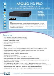
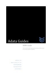
2.3 Front panel (may vary on some models)<br />
(1) IR remoter receiver (2) Power indicator light (3) Alarm indicator light<br />
(4) <strong>HD</strong>D indicator light (5) Record indicator light (6) Network indicator light<br />
(7) Status indicator lighter (8) Running indicator lights (9) Back to main course<br />
(10) PTZ control (11) Playback (12) Previous File<br />
(13) Next File (14) Record (15) Slow Play<br />
(16) Backwards Pause (17) Stop (18) Fast Play<br />
(19) Direction&Enter (20) USB (21) Play Pause<br />
(22) ESC (23) Power Switch<br />
7
Front panel function table<br />
Serial NO Key Mark Function<br />
9 Switch<br />
Function<br />
SHIFT<br />
10 Arrow Move the cursor<br />
Under the state of the user input,can completed switch<br />
function between numeric keys, character keys and other<br />
function keys<br />
<br />
Edit box, press the key you can increase or decrease the digital<br />
Optional drop-down menu, change the settings<br />
Monitor screen, enter the channel 1 or channel 4, singlescreen<br />
monitor<br />
Enter to the text box, press the SHIFT key, press this key to<br />
enter the number 1 or 4<br />
Pop-up menu or submenu, press the left and right arrow keys<br />
move the cursor<br />
Video playback state, press the left and right arrow keys to<br />
move the focus on the function keys<br />
Monitor screen, enter the channel 2 or channel 3 singlescreen<br />
monitor<br />
Enter to the text box, press the SHIFT key, press the button,<br />
enter the number 2 or 3<br />
Enter ENTER Enter<br />
Enter into the Mainmenu<br />
11 Cancel ESC Go back to the previous menu or the function menu to cancel<br />
the operation<br />
In the Video playback state, to return to the real-time<br />
monitoring<br />
12 Power<br />
switch<br />
13 Play the<br />
previous<br />
record<br />
14 Play the<br />
next record<br />
I<br />
I<br />
Press this key to perform boot and shutdown operations<br />
In the state of Video playback, play previous record of the<br />
current playback video ;<br />
In the text box to enter number 1<br />
In the state of Video playback, Play next record of the current<br />
video; In the text box to enter number 2<br />
15 Slow Play I<br />
When playback of video files, a variety of slow-motion speed<br />
and normal playback;<br />
In the text box to enter number 8<br />
16 Fast Play When playback of video files, a variety of fast-forward speed<br />
and normal playback; In the text box to enter number 7<br />
17 Playback/<br />
Pause<br />
II<br />
When playback of video files,play back the video file;<br />
In the text box to enter number 6<br />
18 Play/Pause II When playback of video files, Play/Pause;<br />
In the text box to enter number 5<br />
22 Record REC <strong>Manual</strong>ly start / stop recording, in the video control menu,<br />
used in conjunction with the arrow keys, select the desired<br />
video channel<br />
8
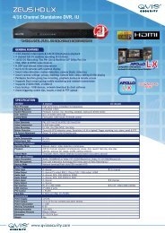
2.4 Rear panel<br />
Note: This is the interface for a 4 channel rear panel of a DVR. See Appendix 3<br />
on page 57 for more details for specific models.<br />
(1) Video input (4) USB (7) VGA<br />
(2) Video output (5) Network (8) Power<br />
(3) Audio output (6) Audio input (9) Switch<br />
Installation sketch map<br />
9
2.5 Audio and video input and output connections<br />
2.5.1 Video input connections<br />
The video input port is a BNC connector plug. The type of input signal is PAL/<br />
NTSC BNC(1.0VP-P,75Ω).<br />
The video signal must be of the correct standard and have a high signal to noise<br />
ratio, low aberration and low interference. The image must be clear and have<br />
natural color and brightness in the environment in which it is to operate.<br />
Insure the vidicon signal is stable and credible<br />
The vidicon should be installed in a suitable location where is away from<br />
backlighting and low illumination or uses backlighting and low illumination<br />
compensation.<br />
The earth and power supply of the vidicon and the DVR should be shared and<br />
stable.<br />
Insure the transmission line is stable<br />
The video transmission line should be a high quality coaxial pair which is suitable<br />
for the transmission distance. If the transmission distance is too great, you should<br />
use shielded twisted pair, video compensation equipment or transmit by fiber<br />
optics to insure the signal quality.<br />
The video signal line should be away from all electro magnetic Interference and<br />
other signal line equipment. High voltage current should be especially avoided.<br />
Insure the connection is stable<br />
The signal and shield lines should be connected with a tight connection which<br />
will help avoid false signals, joint welding and oxidation.<br />
2.5.2 Video output connections and options<br />
The video output is divided into PAL/NTSC BNC(1.0VP-P,75Ω) and VGA output<br />
(selective configuration).<br />
If you replace your <strong>Qvis</strong> monitor with a computer display, there are some issues<br />
to take note of.<br />
1). Do not leave the display turned on for a long time.<br />
2). To ensure normal working demagnetize regularly.<br />
3). Keep the display away from electro magnetic Interference.<br />
A TV is not a suitable replacement for a video output. It can only be used for a<br />
short period of time and is particuarly suseptabler to nearby interferance. The TV<br />
can also damage other equipment.<br />
2.5.3 Audio signal input<br />
The audio port is a BNC connection.<br />
As the input impedance is high, the tone arm must be active.<br />
The audio signal line should be strong and away from any electro magnetic<br />
Interference and with a credible connection which should avoid false signals and<br />
joint welding and oxidation. High voltage current should be especially avoided.<br />
10
2.5.4 Audio signal output<br />
Commonly the output parameter of a DVR audio signal is greater than 200mv<br />
1KΩ(BNC) which can connect a low impedance earphone and active sound box<br />
or other audio output equipments through a power amplifier. If the sound box and<br />
the tone arm can not be isolated, a howling phenomena is often experienced.<br />
Here are some methods to deal with this phenomena.<br />
1). Adopt a better directional tone arm.<br />
2). Adjust the sound box volume to below the threshold that produces the<br />
howling phenomena.<br />
3). Use fitment materials that absorb the sound to reduce the reflection of the<br />
sound.<br />
4). Adjust the layout of the sound box and the tone arm.<br />
2.6 Alarm input and output connections<br />
1. Alarm input<br />
A. Alarm input is grounding alarm input.<br />
B. Alarm input demand is the grounding voltage signal.<br />
C. When the alarm is connected with two DVRs or connected with DVR<br />
and other equipments, it should be isolated by relay.<br />
2. Alarm output<br />
Alarm output can not be connected with high-power load(no more than 1A).<br />
When forming the output loop it must prevent the big current from relay damage.<br />
Use the contact isolator when there is a high-power load<br />
3. PTZ decoder connections<br />
A. The earth for the PTZ decoder and DVR must be shared otherwise<br />
the common-mode voltage will lead to the PTZ control failure. Shielded<br />
twisted pair is recommended.<br />
B. Avoid high voltage. Take precaution against the thunder and lightning.<br />
C. At the outlying end connect a parallel 120Ω resistance to ensure the<br />
signal quality.<br />
D. The 485 AB lines of the DVR can not connected with other 485 output<br />
equipment in parallel.<br />
E. The voltage between the AB lines of the decoder must be less than 5V.<br />
4. Front equipment grounding note<br />
Bad earthing can lead to burnout of the chip.<br />
11
5. Alarm input type unlimited<br />
The DVR alarm output port is constant opening type.<br />
(1) alarm input (2) grounding (3) RS232 (4) alarm output (5) RS485<br />
Parameter<br />
G<br />
Meaning<br />
grounding (earth)<br />
C1, NO1 Alarm output interface(constant open type)<br />
T, R RS232 port<br />
A, B 485communication interface which is connected with the recording<br />
control equipments such as the decoder<br />
2.6.1 Alarm input port specification<br />
8 channels alarm input. Alarm input type unlimited.<br />
The earth and the com port of the alarm sensor are parallel (The alarm sensor<br />
has an external power supply) .<br />
The earth of the alarm and the DVR should be shared.<br />
The NC port of the alarm sensor must be connected with the DVR alarm input<br />
port.<br />
The earth of the power supply and the alarm sensor must be shared when used<br />
in external power supply.<br />
2.6.2 Alarm output port specification<br />
2 channels alarm output. There is an external power supply when using the<br />
external alarm equipment.<br />
Please refer to the relevant relay parameters to avoid overloading that damages<br />
the DVR.<br />
12
2.6.3 Alarm output port relay parameters<br />
Type: JRC-27F<br />
Interface material<br />
Rating<br />
(resistance load)<br />
Silver<br />
Rating switch capacity<br />
Maximal switch power<br />
Maximal switch voltage<br />
Maximal switch current<br />
30VDC 2A, 125VAC 1A<br />
125VA 160W<br />
250VAC, 220VDC<br />
isolation Homo-polarity interface 1000VAC 1minute<br />
Inhomo-polarity interface<br />
Interface and winding<br />
1A<br />
1000VAC 1 minute<br />
1000VAC 1 minute<br />
Surge voltage Homo-polarity 1500VAC (10×160us)<br />
Turn-on time<br />
Turn-off time<br />
3ms max<br />
3ms max<br />
longevity Mechanical 50×106 MIN (3Hz)<br />
Environment temperature<br />
Electric<br />
2.7 Speed dome connections<br />
-40~+70 o C<br />
200×103 MIN (0.5Hz)<br />
1. Connect the 485 lines of the speed dome with the DVR 485 interface.<br />
R485<br />
2. Connect the video line with the DVR video input.<br />
3. Connect the speed dome to a power supply.<br />
13
3 Basic operation<br />
Note: The button in gray display indicates nonsupport.<br />
3.1 Turn on<br />
Plug in and turn on the power supply switch. If the Power supply indicator light<br />
lights up then the video recorder has turned on. After startup you will hear a<br />
beep. The default setting of the video output is a multiple-window output<br />
mode. If the startup time is within a set video recording time, the timing video<br />
recording function will start up automatically. Then the video indicator light of the<br />
corresponding channel will light up to let you know the DVR is working normally.<br />
Note:<br />
1). Make sure that the input voltage corresponds with the switch of the DVR<br />
power supply.<br />
2). Power supply demands: 220V±10% /50Hz.<br />
We suggest using UPS to protect the power supply under allowable conditions.<br />
3.2 Turn off<br />
There are two methods to turn off the DVR. Entering [main menu] and choosing<br />
[turn off] in the [turn off the system] option is called soft switch. Pressing the<br />
power supply switch is called hard switch.<br />
Illumination:<br />
1). Auto resume after power failure<br />
If the DVR is shut down abnormally, it can automatically backup video and<br />
resume the previous working status after a power failure.<br />
2). Replace the hard disk<br />
Before replacing the hard disk, the power supply switch in the rear panel must<br />
be turned off.<br />
3). Replace the battery<br />
Before replacing the battery, the setting information must be saved and the power<br />
supply switch in the rear panel must be turned off. The DVR uses a button<br />
battery. The system time must be checked regularly. If the time is not correct you<br />
must replace the battery, we recommend replacing the battery every year and<br />
using the same battery type.<br />
Note: The setting information must be saved before replacing the battery<br />
otherwise information will be lost.<br />
3.3 System Login<br />
When the DVR boots up, the user must login and the system provides the<br />
corresponding functions in the user preview. There are three user settings. The<br />
names are admin, guest and default and these names have no password. Admin<br />
is the super user preview; guest and default’s permissions are preview and video<br />
playback.<br />
User admin and guest’s password can be revised, while their permissions can’t<br />
be revised; user default is the default login user whose permission can be revised<br />
but not its password.<br />
14
Picture 3.1 System Login<br />
Password protection: If the password is entered continuously wrong for three<br />
times, the alarm will start. If the password is continuously wrong five times, the<br />
account will be locked. (Through a reboot or after half an hour, the account can<br />
be unlocked automatically).<br />
For your system security, please modify your password after first login.<br />
3.4 Preview<br />
You can right click mouse to choose the switch between the windows.<br />
The system date, time and channel name are shown in each viewing window.<br />
The surveillance video and the alarm status are shown in each window.<br />
1 Recording status 3 Video loss<br />
2 Motion detect 4 Camera lock<br />
Table 3.1 Preview icon<br />
3.5 Desktop shortcut menu<br />
In preview mode you can right click your mouse to get a desktop shortcut<br />
menu. The menu includes: main menu, record mode, playback, PTZ control,<br />
High Speed PTZ, Alarm Output, Color Setting, Output adjust, Logout, View<br />
1/4/8/9/16 screens.<br />
15
3.5.1 Main menu<br />
Picture 3.2 Shortcut Menu<br />
When you login, the system main menu is shown as below.<br />
Picture 3.3 Main Menu<br />
16
3.5.2 Playback<br />
There are two methods for you to play the video files in the hard disk.<br />
1). In the desktop shortcut menu.<br />
2). Main menu>Record->Playback<br />
Note: The hard disk that saves the video files must be set as read-write or readonly<br />
state.(4.5.1)<br />
Picture 3.4 video playback<br />
1). Listed files 2). File information 3). File searching<br />
4). File backup 5). Operation hint 6). Playback control<br />
(Listed files) Look up the listed files that accord with the searching criteria.<br />
(File information) Look up the found file information.<br />
(File backup) Backup the chosen file. Click the button and operate as followed.<br />
Note: The storage must be installed before the file backup. If the backup is<br />
terminated, the files already backedup can playback individually.<br />
Picture 3.5 detect the storage<br />
17
Detect: Detect the storage connected with the DVR such as hard disk or universal disk.<br />
Erasure: Choose the file to delete and click erasure to delete the file.<br />
Stop: Stop the backup.<br />
Backup: Click backup button and the dialog box is popped up. You can choose<br />
the backup file according to the type, channel and time.<br />
Picture 3.6 recording backup<br />
Remove: Clear the file information.<br />
Add: Show the file information satisfying the set file attributes.<br />
Start/Pause: Click the play button to start the backup and click the pause button<br />
to stop the backup.<br />
Cancel: During backup you can exit the page layout to carry out other functions.<br />
(File searching) Search the file according to the searching parameter.<br />
Picture 3.7 file searching<br />
File type: Set the searching file type.<br />
Channel: Set the searching channel.<br />
Start Time: Set the searching time scan.<br />
(Playback control) Refer to the following sheet for more information.<br />
18
Button Function Button Function<br />
/ Play/pause Backward<br />
Stop<br />
Fast play<br />
Next frame<br />
Next file<br />
Full screen<br />
Table 3.2 Playback control key<br />
Slow play<br />
Previous frame<br />
Previous file<br />
Circulation<br />
Note: Frame by frame playback is only performed in the pause playback state.<br />
(Operation hint) Display the function of the cursor place.<br />
Special functions:<br />
Accurate playback: Input time (h/m/s) in the time column and then click play<br />
button. The system can operate accurate playback according to the searching<br />
time.<br />
Local zoom: When the system is in single-window full-screen playback mode,<br />
you can drag your mouse in the screen to select a section and then left click your<br />
mouse to view this in local zoom. You can right click your mouse to exit.<br />
3.5.3 Record Mode<br />
Please check the current channel status: “” means it is not in recording mode,<br />
“•” means it is in recording mode.<br />
You can use the desktop shortcut menu or click [main menu]> [recording<br />
function]> [recording set] to enter the recording control interface.<br />
Picture 3.8 Record Mode<br />
Schedule: Record according to the configuration.<br />
<strong>Manual</strong>: Click the all button and the according channel is recording no matter the<br />
channel in any state.<br />
Stop: Click the stop button and the according channel stops recording no matter<br />
the channel in any state.<br />
19
3.5.4 Alarm output<br />
Please check current channel status: “o” means it is not in alarming status, “•”<br />
means it is in alarming status.<br />
You can use desktop shortcut menu or click [main menu]> [alarm function]><br />
[alarm output] to enter the alarm output interface.<br />
Picture 3.9 alarm output<br />
(Configuration) Alarm is on according to the configuration.<br />
(<strong>Manual</strong>) Click the all button and the according channel is alarming no matter<br />
the channel in any state.<br />
(Stop) Click the stop button and the according channel stops alarming no matter<br />
the channel in any state.<br />
3.5.5 PTZ control<br />
The PTZ Operation interface is as followed. The functions include: PTZ direction<br />
control, step, zoom, focus, iris, setup operation, patrol between spots, trail patrol,<br />
boundary scan, assistant switch, light switch, level rotation and so on.<br />
Note:<br />
1). Decoder A(B) line connects with the DVR A (B) line. The connection is right.<br />
2). Click [main menu] >[system configuration] >[PTZ setup] to set the PTZ parameters.<br />
3). The PTZ functions are decided by the PTZ protocols.<br />
Picture 3.10 PTZ setup<br />
20
Speed: Set the PTZ rotation range. Default range: 1 ~ 8.<br />
Zoom: Click / button to adjust the zoom multiple of the camera.<br />
Focus: Click / button to adjust the focus of the camera .<br />
Iris: Click / button to adjust the iris of the camera.<br />
Direction control: Control the PTZ rotation. 8 directions control is supportive.<br />
(4 directions in Front panel is supported )<br />
High speed PTZ: Full-screen shows channel image. Left mouse click to control<br />
the PTZ rotation and orientation. Left click mouse and then rotate the mouse to<br />
adjust the zoom multiple of the camera.<br />
Set: Enters the function operation menu.<br />
Page switch: Switchs between different pages.<br />
Special functions:<br />
1). Preset<br />
To set a preset location, call up the preset points and the PTZ will automatically<br />
turn to the setting position<br />
1). Preset option<br />
To set a location for the preset, the procedure is as follows:<br />
Step 1: In Picture 3.10, use the direction button to turn the PTZ to the preset<br />
position, click the Settings button to enter Picture 3.11.<br />
Step 2: Click on the preset button and then enter the preset point number in<br />
the preset box (shows 0 in box below),<br />
Step 3: Click the Set button to return to Picture 3.10 to complete the setup,<br />
check that the preset points and preset position corresponds.<br />
Clear Preset: Input preset points, click Remove button to remove a preset.<br />
Picture 3.11 Preset Settings<br />
2). To go to a Preset Point<br />
In Picture 3.10, click Page Switch button, enter PTZ control interface as shown in<br />
Picture 3.12. In the input No, type the preset point, then click the preset button,<br />
the PTZ will turn to the corresponding preset point.<br />
21
Picture 3.12 PTZ Control<br />
2: Cruise between Points<br />
A PTZ camera can be set to cruise between a series of preset points. This is called<br />
a cruise. To set the PTZ up to do this is as follows:<br />
1). Cruise Between Points Settings<br />
A cruise line is a set up of multiple preset connected points, the setup procedure<br />
is as follows:<br />
Step 1: In Picture 3.10, use the Direction key to turn the PTZ to a designated<br />
location, click the settings button to enter Picture 3.13,<br />
Step 2: Click the Tour button, enter the tour number into the Patrol Number<br />
box if it isn't already showing and then click Add preset. The number<br />
of presets in the tour will show in the Preset box.<br />
Step 3: repeat steps 1 and 2, until you have set out all the preset designated<br />
cruise positions<br />
Remove Preset: Please input the preset value in the blank, click Remove Preset<br />
button, then remove the preset points.<br />
Remove Cruise Line: Input the number of cruise line, click Remove Cruise Lines<br />
button, then remove the cruise lines set.<br />
Picture 3.13 Cruise Between Points Settings<br />
2). To view Cruise between Points<br />
In Picture 3.10, click the Page Shift button to enter the PTZ control menu as<br />
shown in Picture 3.12. Please input the patrol number of the cruise in the value<br />
blank, then click the Cruise between Points button. The PTZ will cruise from point<br />
to point on the cruise line. Click the Stop button to stop the cruise.<br />
22
3: Scan<br />
The PTZ can also work on the preset scan line repeatedly.<br />
1). Scan setup<br />
Step 1: In Picture 3.10, click the Setup button, which takes you to Picture 3.14;<br />
Step 2: Click the Pattern button and input a patrol value in the pattern value<br />
blank;<br />
Step 3: Click the begin button and enter Picture 3.10, here you can set the<br />
following items: Zoom, Focus, Aperture, Direction and so on. Click Set<br />
button to go back Picture 3.14;<br />
Step 4: Click the End button to complete the setup, Click the right button of<br />
the mouse to exit.<br />
Picture 3.14 Scan Setup<br />
2). Scan Calls<br />
In Picture 3.10, click the Page Shift button to enter the PTZ control menu as<br />
shown in Picture 3.12.<br />
Please input the number of the scan in the value blank , then click the AutoScan<br />
button, the PTZ will begin to work on the scan line . Click the stop button to stop.<br />
4: Boundary Scan<br />
1). Boundary Scan setup<br />
Step 1: In Picture 3.10, click the multi arrow direction button to turn the PTZ<br />
to a left hand boundary position, then click Set button to enter Picture<br />
3.15, select the left boundary, return to Picture 3.10;<br />
Step 2: Please click the multi arrow direction button to adjust the PTZ to the<br />
right boundary, click Set button to enter Picture 3.15, then select the<br />
right boundary, return to Picture 3.10;<br />
Step 3: Complete setup, the position of left and right boundary are now set.<br />
right button click to exit.<br />
Picture 3.15 Boundary Scan Setup<br />
23
2). Boundary Scan Calls<br />
In Picture 3.10, click the Page Shift button to enter the PTZ control menu as<br />
shown in Picture 3.12.<br />
Please input the number of the scan in the value blank , then click the AutoScan<br />
button, the PTZ will begin to work on the scan line . Click the stop button to stop.<br />
5: Rotating the Horizontal<br />
Click the Horizontally Rotating button and the PTZ will begin to rotate horizontally<br />
(relative to the original position of the camera). Click the Stop button to stop.<br />
6: Rotate<br />
Click on the horizontal rotating button and the PTZ will turn around.<br />
7: Reset<br />
The PTZ will restart and clear all the data back to 0.<br />
8: Page Shift<br />
In Picture 3.12, click the Page-Switch button to go to Picture 3.16 (setting the<br />
auxiliary function). Set the auxiliary number corresponding to auxiliary switch on<br />
the decoder.<br />
Picture 3.16 Auxiliary Function Control<br />
(Intuitive Auxiliary Operation) choose auxiliary equipment, select Open or Close<br />
button as the switch control.<br />
(Auxiliary Number) The operation of the corresponding auxiliary switch according<br />
to the PTZ agreement.<br />
(Page Shift) In Picture 3.16 click Page Switch button to enter Picture 3.17 PTZ<br />
Main Menu, the menu itself can be control by the menu control buttons<br />
3.5.6 Color setting<br />
Set the selective image parameters (the current channel for the single window<br />
display and cursor placed for the multi-window display). You can use the desktop<br />
shortcut menu to enter the interface. The image parameters include: tonality,<br />
brightness, contrast, saturation. You can set different parameters at different time<br />
sections.<br />
24
Picture 3.18 Color Setting<br />
3.5.7 Output Adjust<br />
Adjust TV output area parameters. You can use the desktop shortcut menu or<br />
enter [main menu]> [management tools]> [Output adjust].<br />
3.5.8 Logout<br />
Picture 3.19 Output Adjust<br />
To logout, shut down the system or reboot the system. You can use the desktop<br />
shortcut menu or enter [main menu].<br />
Picture 3.20 Logout/Reboot the system<br />
(Logout) Quit the menu. Use to switch user.<br />
(Shut down) Quit the system. Turns off the power supply. When you press the<br />
shut down button, there is schedule hint. After three seconds, the system shuts<br />
down. This cannot be cancelled once the shut down button is pressed.<br />
(Reboot) Quit or Reboot the system.<br />
3.5.9 Window switch<br />
Preview in a single window/four windows/eight windows/nine windows/sixteen<br />
windows according to your choice.<br />
25
4 Main menu<br />
4.1 Main menu navigation<br />
Main menu Sub menu Function<br />
Record Config Set the recording configuration, recording type, recording<br />
time section<br />
Playback<br />
Backup<br />
Set recording look-up, recording play, video file storage<br />
Detect or format backup equipment, back the selective files<br />
Alarm Motion detection Set motion detect alarm channel, sensitivity, area,<br />
linkage parameters: defending time section, alarm<br />
output, screen hint, recording, PTZ, patrol<br />
System<br />
Configuration<br />
Management<br />
tools<br />
Video blind<br />
Video loss<br />
Alarm input<br />
Alarm output<br />
General<br />
configuration<br />
Encode<br />
configuration<br />
Network<br />
configuration<br />
NetService<br />
GUI display<br />
PTZ configuration<br />
Serial port Configuration<br />
(RS232)<br />
Tour<br />
Hard disk<br />
management<br />
User management<br />
Online user<br />
TV adjust<br />
Automatic<br />
maintenance<br />
Restore<br />
Set camera mask alarm channel, sensitivity, linkage<br />
parameters: defending time section, alarm output, screen<br />
hint, recording, PTZ, patrol<br />
Set video loss alarm channel, linkage parameters:<br />
defending time section, alarm output, screen hint,<br />
recording, PTZ, patrol<br />
Set the alarm input channel, equipment type, linkage<br />
parameters: defending time section, alarm output, screen<br />
hint, recording, PTZ, patrol<br />
Set alarm mode: configuration, manual, shut down<br />
Set system time, data format, language, hard disk full<br />
time operation, machine number, video format, output<br />
mode, summertime, stay time<br />
Set main (assistant) coding parameter: code mode,<br />
resolving ability, frame rate, code stream control, image<br />
quality type, code stream value, frame between value,<br />
video/audio enable<br />
Set basic network parameters, DHCP and DNS parameters,<br />
network high speed download<br />
PPPOE, NTP, Email, IP purview, DDNS parameter<br />
Set channel name, preview hint icon state, transparency,<br />
cover area, time title, channel time fold<br />
Set channel, PTZ protocol, address, baud rate, date bit,<br />
stop bit, check<br />
Set serial port function, baud rate, date bit, stop bit,<br />
check<br />
Set patrol mode and interval time<br />
Set appointed hard disk as read-write disc, read-only disc<br />
or redundant disc, clear data, resume date and so on<br />
Modify user, team or password. Add user or team. Delete<br />
user or team.<br />
Break the connection with the already login user. Lock<br />
the account after break until booting up again.<br />
Adjust TV upside, downside, nearside, starboard distance<br />
Set automatic reboot system and automatic deleting files.<br />
Resume setup state: common setup, code setup, recording<br />
setup, alarm setup, network setup, network service,<br />
preview playback, serial port setup, user management<br />
26
Main menu Sub menu Function<br />
System<br />
information<br />
Shut down<br />
Hard disk information<br />
Code stream statistics<br />
Log information<br />
Edition information<br />
Display hard disk capability and recording time<br />
Display code stream information<br />
Clear all log information according to the log video and<br />
time<br />
Display edition information<br />
Logout or reboot<br />
4.2 Record<br />
4.2.1 Record Configuration<br />
To set the recording parameters in the surveillance channel. The system is set<br />
up for 24 hours consecutive recording in the first startup. You can enter [main<br />
menu]> [recording function]> [recording setup] to set.<br />
Note:There must be at least one read-write hard disk.(refer to chapter 4.5.1)<br />
Picture 4.1 Record Config<br />
(Channel) Choose the corresponding channel number to set the channel. Choose<br />
the all option to set every channel to the same.<br />
(Redundancy) Choose the redundancy function option to implement the file<br />
double backup function. Double backup is writing the video files to two hard<br />
disks. When you do the double backup, make sure that there are two hard disks<br />
installed. One is read-write disk and the other is redundant disk. (refer to 4.5.1)<br />
(Length) Set the time length of each video file. 60 minutes is the default value.<br />
(PreRecord) Record 1-30 seconds before the action. (time length is decided by<br />
the code stream)<br />
(Record mode) Set the video state: schedule, manual or stop.<br />
Schedule: Record according to the set video type (common, detection and alarm)<br />
and time section.<br />
<strong>Manual</strong>: Click the button and the relevant channel will start recording no matter<br />
what else the channel has been set to do.<br />
Stop: Click the stop button and the relevant channel stops recording no matter<br />
what else the channel has been set to do.<br />
27
(Period) Set the time section for common recording, The recording will start only<br />
within the set range.<br />
(Record type) Set recording type: regular, detection or alarm.<br />
Regular: Perform regular recording in the set time section. The video file type is “R”.<br />
Detect: Trigger the “motion detect”, “camera mask” or “video loss” signal. When<br />
the above alarm is set as the opening recording, the “detection recording” state<br />
is on. The video file type is “M”.<br />
Alarm: This triggers the external alarm signal in the set time section. When the<br />
above alarm is set as the opening recording, the “detection recording” state is set<br />
to on. The video file type is “A”.<br />
Note: Refer to chapter 4.3 to set corresponding alarm function.<br />
4.2.2 Snapshot Storage<br />
Setup snapshot parameters for different channels.At first time it's set for 24hours<br />
snapshot continuously, pls go to Main Menu->Record->Snapshot Storage for<br />
appropriate settings.<br />
Note:If normal snapshot storage,pls setup Snap at Main Menu->Advanced-<br />
>Snapshot(pls refer to chapter 4.5.1 <strong>HD</strong>D Manage)<br />
Picture 4.2<br />
(Channel) Select the related channel to set,click "all" to set all channels.<br />
(Presnap) Setup presnap picture quantity before recording,default is 5 pieces.<br />
(Record) Set record status,"Schedule","<strong>Manual</strong>" and "Stop"<br />
Schedule:Realise snapshot according to record type(regular,detect and alarm)<br />
and period.<br />
<strong>Manual</strong>:No matter what the present channel is in a state,once choose "manual"<br />
button,it will have snapshot at related channels.<br />
Stop:No matter what the present channel is in a state,once choose "stop" button,it<br />
will stop snapshot at related channels.<br />
(Period) Set normal record period,it only startup Snapshot Storage at set period.<br />
(Type) Three types:regular,detect and alarm<br />
(Record type) Three types:regular,detect and alarm<br />
Regular: snapshot at set period<br />
Detect:snapshot at set period when motion detect,video blind and video loss<br />
which are preset for snapshot enable.<br />
Alarm:snapshot at set period when alarm in which is preset for snapshot enable.<br />
Note:for related alarm function,pls refer to chapter 4.3.<br />
28
4.2.3 Playback<br />
Refer to chapter 3.5.2.<br />
4.2.4 Backup<br />
You can backup the video files to external storage through setup.<br />
Note: The storage must be installed before the file backup. If the backup is<br />
terminated, the files already backed up can be played back individually.<br />
Picture 4.3 Backup<br />
(Detect) Detects the storage connected with the DVR such as hard disk or<br />
universal disk.<br />
(Erase) Choose the file to delete and click erasure to delete the file.<br />
(Stop) Stop the backup.<br />
(Backup) Click backup button and the dialog box pops up. You can choose the<br />
backup file according to type, channel and time recorded.<br />
Picture 4.4 File Backup<br />
Remove: Clear the file information.<br />
Add: Show the file information to satisfy the set file attributes.<br />
Start/pause: Click the play button to start the backup and click the pause button<br />
to stop the backup.<br />
Cancel: During backup you can exit the page layout to carry out other functions.<br />
29
4.3 Alarm Function<br />
Alarm functions include: motion detect, video blind, video loss, alarm input and<br />
alarm output.<br />
4.3.1 Motion Detect<br />
When the system detects a motion signal that reaches the set level of sensitivity,<br />
the motion detect alarm is switched on and the linkage function is turned on.<br />
Picture 4.4 Motion Detect<br />
(Channel) Choose the set motion detect channel.<br />
(Enable) • means that the motion detect function is on.<br />
(Sensitivity) Choose in the six options according to the sensitivity.<br />
(Region) Click setup and enter the set area. The area is divided into PAL 8x8.<br />
Green block means the current cursor area. Yellow block means the dynamic<br />
detect defensive area. Black block means the unfenced area. You can set the area<br />
as followed, Drag the mouse and draw the area.<br />
Picture 4.5 Region<br />
(Period) Trigger the motion detect signal in the set time section. You can set<br />
according to week or set uniformly. Each day is divided into four time sections.<br />
• means the setup is valid.<br />
30
Picture 4.6 set the time section<br />
(Interval) Only one alarm signal is turned on even if there are several motion<br />
detection signals in the set interval.<br />
(Alarm output) Starts the external equipment of the linked alarm when the motion<br />
detect alarm is turned on.<br />
(Delay) Delay a few moments and stop when the alarm state is turned off. The<br />
range is 10~300 seconds.<br />
(Record channel) Choose the recording channel (multiple options are supported).<br />
Trigger the video signal when the alarm is turned on.<br />
Note: Set in the [recording setup] and perform the linked recording. Start detecting<br />
video files in the corresponding time section.<br />
(Tour) • means that the selected channel is a single window alternate patrol<br />
preview. The interval is set in the [MainMenu]>[System] > [Tour].<br />
(Snapshot) Choose record channels, when the alarm activates, the system<br />
triggers the related channels for a snapshot signal.<br />
Note: For snapshot activation, please go to set period, detect and alarm enable at<br />
MainMenu->Record->Record config,<br />
(PTZ Activation) Set the PTZ activation when the alarm is turned on.<br />
Note: PTZ activation is set in the [shortcut menu] >[ PTZ control]. Set the patrol<br />
between spots, trail patrol and so on.<br />
Picture 4.8 PTZ Activation<br />
(Delay) When alarm is over, recording will last a few seconds(10~300sec),then<br />
stop.<br />
(Show message) Pops the alarm information dialog box into the local host<br />
computer screen.<br />
(Send EMAIL) means sending an email to the user when the alarm is turned on.<br />
Note: Set in the [NetService] and send email.<br />
31
4.3.2 Video Blind<br />
When the video image is influenced by environmental factors such as excessive<br />
brightness or reaching the set sensitivy parameter, the camera mask function and<br />
the linkage function are turned on.<br />
Picture 4.9 Video Blind<br />
Set method: refer to chapter 4.3.1. Motion detect<br />
Note: "Advanced" button is the same as right-click.<br />
4.3.3 Video Loss<br />
When the equipment can not obtain the channel video signal, the video loss<br />
alarm is turned on and the linkage function is turned on.<br />
Picture 4.10 Video loss<br />
Set method: refer to chapter 4.3.1. Motion detect<br />
Note: "Advanced" button is the same as rightclick.<br />
32
4.3.4 Alarm input<br />
When the system gets an external alarm signal, the alarm function is turned on.<br />
Picture 4.11 Alarm input<br />
Set method: refer to chapter 4.3.1. Motion detect<br />
Note:"Advanced" button is the same as rightclick.<br />
4.3.5 Alarm output<br />
4.3.4 Abnormal<br />
Refer to chapter 3.5.4.<br />
Analysing and inspecting current software and hardware of the device: When<br />
some abnormal events happen, the device will make a relative answer such as<br />
show message and buzzer.<br />
Picture 4.12 Abnormal<br />
(Event Type) Selecting the abnormity you want to inspect<br />
(Enable) Select it to make sure the abnormal function works<br />
(Show message) Automatically an alarm cue dialog box comes up on the main<br />
screen<br />
(Buzzer) The device will have a “di di” noise when the alarm is sounding<br />
33
4.4 System setup<br />
Set the system parameters such as General, Encode, NetWork, NetService,<br />
GUI Display, PTZ Config, RS232 and Tour Setup.<br />
4.4.1 General<br />
Picture 4.13 General setup<br />
(System time) Set the system data and time.<br />
(Date format) Choose the data format: YMD, MDY, DMY.<br />
(Date Separator) Choose list separator of the data format.<br />
(Time Format) Choose time format: 24-hour or 12-hour.<br />
(Language) Arabic, Czech, English, Finnish, Greek, Indonesian, Italian, Japanese,<br />
Portuguese, Russian, Thai, T-Chinese, S-Chinese, Turkish, Brazilian, Bulgarian,<br />
Farsi, French, German, Hebrew, Hungarian, Polish, Romanian, Spanish, Swedish,<br />
Vietnamese<br />
(<strong>HD</strong>D full) Choose stop record: Stop recording when the hard disk is full Choose<br />
overwrite: Cover the earliest recording files and continue recording when the<br />
hard disk is full.<br />
(DVR No.) Only when the address button in the remote controller and the<br />
corresponding DVR number is matched, the remote operation is valid.<br />
(Video Standard) PAL or NTSC.<br />
(Auto Logout) Set the latency time in 0-60. 0 means no latency time.<br />
(DST) Choose the summer time option and pop the dialog box as followed.<br />
Picture 4.14 DST (week)<br />
Picture 4.15 DST (date)<br />
34
4.4.2 Encode setup<br />
Set the video/audio code parameters: video file, remote monitoring and so on.<br />
Set every independent channel’s coding parameter in the left part, and set the<br />
combine encode parameter in the right part.<br />
Note: Combine encode introduces video compression technique which combines<br />
and compresses multi-channel’s video to a special channel. Applying for multichannel<br />
playback simultaneously, Dial-up multi-channel real-time monitor,<br />
mobile monitor and so on.<br />
Picture 4.16 Encode setup<br />
(Channel) Choose the channel number.<br />
(Compression) Standard H.264 main profile.<br />
(Resolution) Resolution type:D1/ <strong>HD</strong>1/CIF / QCIF.<br />
(Frame Rate) P:1 frame/s~25 frame/s; N: 1 frame/s~30 frame/s<br />
(Bit Rate Type) You can choose limited code stream or variable code stream.<br />
When you choose the variable code stream there are six image quality options.<br />
(Bit Rate) Set the code stream value to modify the image quality. The larger code<br />
stream value the better image quality.<br />
D1(1000~1500kbps) ,CIF(384~1500kbps) , QCIF(64~512kbps)<br />
(Video/Audio) When the icons are all displayed in reverse, the video file is video<br />
and audio multiplex stream.<br />
Combine Enable<br />
(Combine Enable) When the icons are all in reverse displayed, opening<br />
combination coding functions.<br />
(Mode) multi-channel playback is used in all channels to playback simultaneously,<br />
and the narrowband transmission is used in multi-channel real-time remote<br />
monitoring simultaneously at narrowband state, especially used with a mobile<br />
screen.<br />
35
4.4.3 Network setup<br />
Picture4.17 Network<br />
(Net Card) You can choose cable network card or wireless network card.<br />
(DHCP Enable) Obtain IP address automatically (not suggested)<br />
Note: DHCP server is preinstalled.<br />
(IP address) Set the IP address. Default: 192.168.1.10.<br />
(Subnet mask) Set the subnet mask code. Default: 255.255.255.0.<br />
(Gateway) Set the default gateway. Default: 192.168.1.1.<br />
(DNS setup) Domain Name Server. It translates the domain name into IP address.<br />
The IP address is offered by network provider. The address must be set and<br />
reboot then it works.<br />
(TCP port) Default: 34567.<br />
(HTTP port) Default: 80.<br />
(HS Download)<br />
(Transfer Policy) There are three strategies: self-adaption, image quality<br />
precedence and fluency precedence. The code stream will adjust according to the<br />
setup. Self-adaption is the tradeoff between the image quality precedence and<br />
fluency precedence. Fluency precedence and self-adaption are valid only when<br />
the assistant code stream is turned on. Otherwise the image quality precedence<br />
is valid.<br />
4.4.4 NetService<br />
Choose the network service option and click the set button to configure the<br />
advanced network functions or double click the service button to configure the<br />
parameters.<br />
Picture 4.18 NetService<br />
36
(PPPoE setup)<br />
Picture 4.19 PPPOE<br />
Input the user name and password that the ISP (Internet service provider)<br />
provides. After saving it reboot your system. Then the DVR will build a network<br />
connection based on PPPoE. The IP address will change into a dynamic IP<br />
address after the above operation is done.<br />
Operation: After PPPoE dialing is successfully look up the IP address in the [IP<br />
address] and obtain the current IP address. Then use this IP address to visit the<br />
DVR through user port.<br />
(NTP setup)<br />
Picture 4.20 NTP<br />
The NTP server must be installed in the PC.<br />
Host computer IP: Input the IP address installed NTP server.<br />
Port:Default: 123. You can set the port according to NTP server.<br />
Time zone: London GMT+0, Berlin GMT +1, Cairo GMT +2, Moscow GMT +3,<br />
New Delhi GMT +5, Bangkok GMT +7, Hongkong Beijing GMT +8, Tokyo GMT<br />
+9, Sydney GMT +10, Hawaii GMT-10, Alaska GMT-9, Pacific time GMT-8,<br />
American mountain time GMT-7, American mid time GMT-6, American eastern<br />
time GMT-5, Atlantic time GMT-4, Brazil GMT-3, Atlantic mid time GMT-2.<br />
Update Period:The same with the NTP server check interval. Default: 10minutes.<br />
37
(EMAIL setup)<br />
If the alarm is turned on or the alarm linkage photos are taken, the system can<br />
send an email of the alarm information and the photos to an appointed address.<br />
Picture 4.21 EMAIL<br />
SMTP server: Email server address. This could be an IP address or a domain<br />
name. A domain name can only be used if it has the correct DNS configuration.<br />
Port: Email server port number.<br />
SSL: Decide whether to use Secure Socket Layer protocol to login.<br />
User Name: Apply the email server user name.<br />
Password: Input the user password.<br />
Sender: Set the senders email address.<br />
Receiver: Send the email to the appointed receiver(s) when the alarm is turned<br />
on. You can set up to three receivers.<br />
Title: You can set this as you wish.<br />
(IP Filter setup)<br />
When choosing from the white list, only those IP addresses listed can connect to<br />
the DVR. Up to 64 IP addresses are supported in this white list.<br />
When choosing from the black list, only these listed IP addresses cannot connect<br />
to the DVR. Up to 64 IP addresses are supported in this black list.<br />
You can delete the set IP address by √ in the options.<br />
Note: When the same IP address is in the white and black list at the same time,<br />
the black list takes precedence.<br />
Picture 4.22 IP IP FILTER<br />
38
(DDNS) (dynamic domain name server).<br />
Local domain name: Insert the domain name registered by the DDNS.<br />
User name: Insert the user name.<br />
Password: Insert the password.<br />
When the DDNS is successfully configured and started, you can connect the<br />
domain name in the IE address column to visit.<br />
Note: The DNS setup must be configured correctly in the network setup.<br />
Picture 4.23 DDNS setup<br />
(FTP setup) FTP is available only when an alarm happens, or an alarm activates a<br />
record and takes a snapshot, it will then upload the related records and snapshot<br />
pictures to the FTP server.<br />
Picture 4.24 FTP setup<br />
(Enable) Click Enable, to activate all settings<br />
(Server IP) The IP address for the FTP server<br />
(Port) Domain Port of FTP, the default is 21<br />
(User Name) User name of the FTP<br />
(Password) Password of user<br />
(Max File Length) Max length for upload files at every packed, default 128M<br />
(DirName) Directory of uploading files<br />
39
(ARSP)<br />
Startup DDNS server to add devices and manage it in the DDNS server<br />
Type: choose "DNS"<br />
Enable: • means it is chosen<br />
Sever IP: IP address of DDNS server<br />
Port:<br />
(Wireless Config) ADSL through 3G net card,use CMS to visit and config the<br />
device<br />
Picture 4.25 Wireless Config<br />
(Enable) Choose Enable to make all settings available<br />
(Type) Dial type,default AUTO<br />
(Wireless AP) 3G access point<br />
(Dial Number) 3G Dial Number<br />
(User Name) User name of 3G<br />
(Password) Password of dial user<br />
(IP Address) IP address,got from dial<br />
(Mobile Monitor Setup)<br />
To visit the device by mobile,pls make a router mapping of this port and use<br />
CMS to monitor and operate it by protocol.<br />
Picture 4.26 Mobile Monitor Setup<br />
40
(Enable) Select this to make sure the abnormal function is working<br />
(Port) This is the port to enable mobile monitoring. You will need to make a router<br />
map of it if you want to view everything by mobile<br />
(UPNP) UPNP protocol can set auto port forwarding on the router, make sure<br />
UPNP is running on the router before useing it.<br />
Picture 4.27<br />
(Enable) Choose Enable to make sure all UPNP settings available<br />
(HTTP) Route will automatically distribute HTTP port for the device,when IE<br />
viewing,it need this port(eg. 60.12.9.26:66)<br />
(TCP) Router will automatically distribute TCP port for the device,when monitoring<br />
via CMS,it need this port.<br />
(MobilePort) Router will automatically distribute Mobile Port for the device,when<br />
mobile monitor,it need this port.<br />
(WIFI) Through wireless network to connect with the DVR.<br />
(Search) search SSID of wireless LAN<br />
(Enable) Select it to enable the function<br />
(SSID) SSID name<br />
(Password) password of WIFI<br />
(IP Address) IP address of WIFI<br />
(Subnet Mask) Subnet mask of WIFI<br />
(Gateway) Gateway of WIFI<br />
41
4.4.5 GUI Display<br />
Configure the video output parameters including the front output mode and code<br />
output mode.<br />
Front output: In the local preview mode and includes: channel title, time display,<br />
record status, alarm status, bitrate info, transparency and region cover.<br />
Code output:In the network surveillance and video file mode include: channel<br />
title, time display, record status, alarm status, bitrate info, transparency and<br />
region cover.<br />
Picture 4.28 GUI Display<br />
(Channel Title) Click the channel name modify button and enter the channel<br />
name menu. Modify the channel name as required.<br />
(Time Display) means the selected state. This displays the system data and time<br />
in the surveillance window.<br />
(Channel Title) means the selected state. This displays the system channel<br />
number in the surveillance window.<br />
(Record Status) means the selected state. This displays the system recording<br />
status in the surveillance window.<br />
(Alarm Status) means the selected state. This displays the system alarm status<br />
in the surveillance window.<br />
(Bitrate info) means the selected state. The ninth window displays the code<br />
stream information in the nine-window preview status.<br />
(Transparency) Choose the background image level of transparency. The range<br />
is 128~255.<br />
(Resolution) set the display resolution.<br />
(Channel) Choose the set code for the output channel number.<br />
(Region Cover) means the selected state. Click the cover area button and enter<br />
the corresponding channel window. You can cover arbitarily using the mouse.<br />
(the black region is for output)<br />
(Time display)<br />
(Channel Title)<br />
42
4.4.6 PTZ setup<br />
Picture 4.29 PTZ setup<br />
(Channel) Choose the dome camera input channel.<br />
(Protocol) Choose the corresponding dome protocol. (PELCOD as an example)<br />
(Address) Set as the corresponding dome address. Default: 1.<br />
(Note: The address must be consistent with the dome address.)<br />
(Baud rate) Choose the corresponding dome baud rate length. You can control<br />
the PTZ and vidicon. Default: 115200.<br />
(Data bits) Include 5-8 options. Default: 8.<br />
(Stop bits) Include 2 options. Default: 1.<br />
(Parity) Include odd check, even check, sign check, blank check. Default: void.<br />
4.4.7 RS232 setup<br />
Picture 4.30 RS232 setup<br />
(Serial Port Function) Common serial port is used to debug and update program<br />
or set up specific serial port.<br />
(Baud rate) Choose the corresponding baud rate length.<br />
(Data bits) Include 5-8 options.<br />
(Stop bits) Include 2 options.<br />
(Parity) Include odd, even, mark, space.<br />
43
4.4.8 Tour setup<br />
Set the patrol display. • means that the tour mode is turned on. You can choose<br />
the single window, four windows, nine windows, sixteen windows patrol display<br />
or single display.<br />
Picture 4.31 tour setup<br />
(Interval) Set the patrol switch interval. The set range is 5-120 seconds.<br />
Note: / means turn off/on the patrol.<br />
4.5 Advanced<br />
4.5.1 <strong>HD</strong>D Manage<br />
Configure and manage the hard disk. The menu displays current hard disk<br />
information: hard disk number, input port, type, status and overall capability. The<br />
operation include: setup the write-read disk, read-only disk, redundant disk, hard<br />
disk format, resume default. Choose the hard disk and click the right function<br />
button to execute.<br />
Note: Read/Write Disk:The equipment can write or read data.<br />
Read-only Disk:The equipment can read data but can not write data.<br />
Redundant Disk:Double backup the video files in the write-read disk.<br />
Picture 4.32 <strong>HD</strong>D Manage<br />
44
4.5.2 Account<br />
Manage the user purview.<br />
Note: 1. The maximum character length is 8 bytes for the following user and<br />
user team name. A blank ahead of or behind a character string is<br />
invalid. A middle blank in the character string is valid. Legal<br />
characters include: letters, numbers, underline, subtraction sign, dot.<br />
2. There is no limit to the number of users or user groups.<br />
You can add or delete a user group according to the user definition.<br />
The factory setup includes: user\admin. You can set the team as you<br />
wish. The user can appoint the purview in the group.<br />
3. User management includes: group/ user. The group and user name<br />
can not be the same. Each user only belongs to one group.<br />
Picture 4.33 Account<br />
(Modify User) Modify the existed user attribute.<br />
(Modify Group) Modify the existed team attribute.<br />
(Modify Password) Modify a user password. You can set 1-6 bit passwords. A<br />
blank at the beginning or end of the attribute is invalid. A blank in the middle of<br />
the attribute is valid.<br />
Note:The user who possesses the user control authority can modify his/her own<br />
or other users passwords.<br />
Picture 4.34 Modify Password<br />
45
(Add user) To add a user to the team and set the user authority. Enter the menu<br />
interface and input the user name and password. Choose the team and choose<br />
whether cover using is to be activated. Cover using means that the account can be<br />
used by multiple users at the same time.<br />
Once you choose the team, the user authority is in the subclass of that team.<br />
We recommend that the common user’s authority is lower than the advanced user.<br />
Picture 4.35 add user<br />
(Add Group) To add a new user team and set their authority. There are 36<br />
different authorities: shut down the equipment, real time surveillance, playback,<br />
recording setup, video file backup and so on.<br />
Picture 4.36 Add Group<br />
(Delete User) Delete the current user. Choose the user and click delete user<br />
button.<br />
(Delete Group) Delete the current group. Choose the group and click delete group<br />
button.<br />
Picture 4.37 Delete Group<br />
46
4.5.3 Online User<br />
Look up the network user information in the local DVR. You can choose the<br />
network user and cut the connection. Then the user is locked until next bootstrap.<br />
Picture 4.38 Online User<br />
4.5.4 TV adjust<br />
Refer to chapter 3.5.7.<br />
4.5.5 Auto Maintain<br />
The user can set the auto reboot time and auto file deleting time limit.<br />
4.5.6 Restore<br />
Picture 4.39 Auto maintain<br />
The system is restored to the default setup. You can choose the items according<br />
to the menu.<br />
Picture 4.40 Restore<br />
47
4.5.7 Upgrade<br />
Picture 4.41 Upgrade<br />
(Upgrade) choose USB interface.<br />
(Upgrade file) choose the file which needs upgraded.<br />
4.5.8 Device Info<br />
Provide device interface info like audio in,alarm in/out to be conveniently used<br />
for user.<br />
4.6 Info<br />
4.6.1 <strong>HD</strong>D info<br />
Picture 4.42 Device Info.<br />
Display the hard disk state: hard disk type, overall capability, residual capability,<br />
the recording time and so on.<br />
Picture 4.43 <strong>HD</strong>D Info<br />
48
Clue: means that the hard disk is normal.<br />
X means that the hard disk is not working.<br />
- means that there is no hard disk.<br />
If the user needs to change the damaged hard disk then you must shut down the<br />
DVR and remove all the damaged hard disks before installing a new one.<br />
* behind serial number means the current working disk such as 1*. If the<br />
corresponding disk is damaged, the information will show as “?”.<br />
4.6.2 BPS<br />
Displays the code stream (Kb/S) and hard disk capability (MB/H) in real time. It<br />
displays as a wave sketch map.<br />
4.6.3 LOG<br />
Picture 4.44 BPS<br />
Look up the system log according to the set mode.<br />
Log information includes: the system operation, the configuration operation,<br />
data management, alarm affairs, recording operations, user management, file<br />
management and so on. Set the time section to look up and then click the look<br />
up button. The log information will display as a list. (one page is 128 items) Press<br />
Page up or Page down button to look up and press delete button to clear all the<br />
log information.<br />
Picture 4.45 LOG<br />
49
4.6.4 Version<br />
Display the basic information such as hardware information, software edition,<br />
issue data and so on.<br />
4.7 Shut down system<br />
Refer to chapter 3.5.8.<br />
Picture 4.46 Version<br />
50
5 FAQ and maintenance<br />
5.1 FAQ<br />
If your problems is not listed, please contact your local installer for service.<br />
1). The DVR can not boot up normally.<br />
Possible reasons are as followed:<br />
1 The power supply is not correct.<br />
2 Switch power supply line is not in good connection.<br />
3 Switch power supply is damaged.<br />
4 The program updating is wrong.<br />
5 The hard disk is damaged or the hard disk lines are broken.<br />
6 The front panel is damaged.<br />
7 The main board of the DVR is damaged.<br />
2). The DVR reboots automatically or stops working after boot up a few<br />
minutes.<br />
Possible reasons are as followed:<br />
1 The input voltage is not stable or too low.<br />
2 The hard disk is damaged or the hard disk lines are broken.<br />
3 The power of the switch power supply is low.<br />
4 Frontal video signal is not stable.<br />
5 Bad heat radiator or too much dust or bad running circumstance for the DVR.<br />
6 The hardware of the DVR is damaged.<br />
3). System can not detect hard disk.<br />
Possible reasons are as followed:<br />
1 The hard disk power supply line is not connected.<br />
2 The cables of the hard disk are damaged.<br />
3 The hard disk is damaged.<br />
4 The SATA port of main board is damaged.<br />
4). There are no video outputs in single channel, multiple channels and<br />
all channels.<br />
Possible reasons are as followed:<br />
1 The program is not matched. Please update the program.<br />
2 The image brightness is all 0. Please restore the default setup.<br />
3 There is no video input signal or the signal is too weak.<br />
4 The channel protection or the screen protection is set.<br />
5 The hardware of the DVR is damaged.<br />
51
5). Real-time image problems such as the image color or the brightness<br />
distortion.<br />
Possible reasons are as followed:<br />
1 When using the BNC output, the option between the N mode or PAL<br />
mode is wrong and the image becomes black and white.<br />
2 The DVR is not matched the monitor impedance.<br />
3 The video transmission distance is too far or the loss of the video trans<br />
mission line is too large.<br />
4 The color and brightness setting of the DVR is wrong.<br />
6). I can not find the video files in local playback mode.<br />
Possible reasons are as followed:<br />
1 The data line of the hard disk is damaged.<br />
2 The hard disk is damaged.<br />
3 Update the different program with the origin program files.<br />
4 The video files to look up are covered.<br />
5 The recording is not on.<br />
7). The local video is not clear.<br />
Possible reasons are as followed:<br />
1 The image quality is too bad.<br />
2 The reading program is wrong. Reboot up the DVR.<br />
3 The data line of the hard disk is damaged.<br />
4 The hard disk is damaged.<br />
5 The hardware of the DVR is damaged.<br />
8). There is no audio signal in the surveillance window.<br />
Possible reasons are as followed:<br />
1 It is not an active tone arm.<br />
2 It is not an active sound box.<br />
3 The audio lines are damaged.<br />
4 The hardware of the DVR is damaged.<br />
9). There is audio signal in the surveillance window but no audio signal<br />
in the playback state.<br />
Possible reasons are as followed:<br />
1 Setting issues: the audio option is not chosen.<br />
2 The according channel is not connected with the video.<br />
10). The time is wrong.<br />
Possible reasons are as followed:<br />
1 Setting is wrong..<br />
2 The battery is in bad connection or the voltage is too low.<br />
3 The oscillation is damaged.<br />
52
11). The DVR can not control the PTZ.<br />
Possible reasons are as followed:<br />
1 There is something wrong with the frontal PTZ.<br />
2 The setting, connection or the installation of the PTZ decoder is not<br />
correct.<br />
3 The connections are not correct.<br />
4 The PTZ setting of the DVR is not correct.<br />
5 The protocols of the PTZ decoder and the DVR are not matched.<br />
6 The address of the PTZ decoder and the DVR are not matched.<br />
7 When multiple decoders are connected, the far port of the PTZ decoder<br />
line A(B) must connect a 120 Ω resistance to reduce the reflection<br />
otherwise the PTZ control is not stable.<br />
8 The distance is too far.<br />
12). The motion detect is not working.<br />
Possible reasons are as followed:<br />
1 The time range set is not correct.<br />
2 The motion detect area set is not correct.<br />
3 The sensitivity is too low.<br />
4 Limited by some hardware edition.<br />
13). I can not login via web or CMS.<br />
Possible reasons are as followed:<br />
1 The system is windows 98 or win me. We recommend updating to win<br />
dows 2000sp4 or higher Version or installing the software for low<br />
edition.<br />
2 ActiveX is hold back.<br />
3 The version is not exceeded dx8.1. Update the display card driver.<br />
4 Network connection failure.<br />
5 Network setting issues.<br />
6 Invalid password or user name.<br />
7 The CMS is not matched the DVR program version.<br />
14). The image is not clear or there is no image in network preview state<br />
or video file playback state.<br />
Possible reasons are as followed:<br />
1 Network is not stable.<br />
2 The user machine is resource limited.<br />
3 Choose the play-in-team mode in the network setup of DVR.<br />
4 The region shelter or channel protection is set.<br />
5 The user has no surveillance purview.<br />
6 The real-time image of the hard disk recording machine itself is not<br />
clear.<br />
53
15). Network connection is not stable.<br />
Possible reasons are as followed:<br />
1 Network is not stable.<br />
2 IP address is conflicted.<br />
3 MAC address is conflicted.<br />
4 The net card of the DVR is bad.<br />
16). There is something wrong with the USB backup or writing a CD.<br />
Possible reasons are as followed:<br />
1 The rewritable machine and the hard disk are shared the same data<br />
lines.<br />
2 The data is too much. Please stop recording and backup.<br />
3 The data exceeds the backup storage.<br />
4 The backup equipment is not compatible.<br />
5 The backup equipment is damaged.<br />
17). The keyboard can not control the DVR.<br />
Possible reasons are as followed:<br />
1 The serial port of the DVR is not set correctly.<br />
2 The address is not correct.<br />
3 When multiple transformers are connected, the power supply is not<br />
large enough. Please give each transformer individual power supply.<br />
4 The distance is too far.<br />
18). Alarm can not be recessional.<br />
Possible reasons are as followed:<br />
1 The setting of the alarm is not correct.<br />
2 The alarm output is turned on manually.<br />
3 The input machine is damaged or the connections are not correct.<br />
4 There are some problems for specific program edition, Please update the program.<br />
19). Alarm is not working.<br />
Possible reasons are as followed:<br />
1 The setting of the alarm is not correct.<br />
2 The connection of the alarm is not correct.<br />
3 The alarm input signal is not correct.<br />
4 A alarm is connected with two loops synchronously.<br />
20). The remote controller is not working.<br />
Possible reasons are as followed:<br />
1 The remote control address is not correct.<br />
2 The remote control distance is too far or the angle is too large.<br />
3 The battery is used up.<br />
4 The remote controller or the front panel of the recording machine is<br />
damaged.<br />
54
21). The storage time is not enough.<br />
Possible reasons are as followed:<br />
1 Front vidicon quality is bad. The lens is too dirty. The vidicon is in back<br />
lighting installation.<br />
2 The hard disk capability is not enough.<br />
3 The hard disk is damaged.<br />
22). The downloading files can not play.<br />
Possible reasons are as followed:<br />
1 There is no media player.<br />
2 There is no DX8.1 software or higher edition.<br />
3 There is no DivX503Bundle.exe file to play AVI video files.<br />
4 The DivX503Bundle.exe and ffdshow-2004 1012 .exe files must be<br />
installed in the windows xp system.<br />
23). I can not remember the advanced code or network code in the local<br />
menu operation.<br />
Please contact the local service or call the HQ service. We will offer<br />
the service according the machine type and the program edition.<br />
5.2 Maintenance<br />
1 Please brush the printed circuit boards, connectors, fans, machine box and<br />
associated parts regularly.<br />
2 Please keep the earth well conected to prevent the video or audio signal<br />
from interfering with the DVR and from static or inductive electricity.<br />
3 Do not pull out the video signal line or RS-232 port or RS-485 port with<br />
the power on.<br />
4 Do not use a TV in the local video output port(VOUT) of the DVR. It will<br />
easily damage the video output circuit.<br />
5 Do not turn off the power directly. Please use the turn-off function in the<br />
menu or press the turn-off button in the panel (3 seconds or longer) to<br />
protect the hard disk.<br />
6 Please keep the DVR away from any heat resource.<br />
7 Please keep the DVR well ventilated for better heat radiation.<br />
8 Please check the system and maintain regularly.<br />
55
Appendix 1.Remote controller operation<br />
(6)(1) (5) (8)(7) (4) (3) (2)<br />
Serial Number Name Function<br />
1 Multi-window button Same function as Multi-window button in the front panel<br />
2 Numeric button Code input/number input/channel switch<br />
3 (Esc) Same function as (Esc) button in the front panel<br />
4 Direction button Same function as direction button in the front panel<br />
5 Record control Control the record<br />
6 Record mode Same function as “Record mode”<br />
7 ADD Input the number of DVR to control it<br />
8 FN Assistant function<br />
Appendix 2.Mouse operation<br />
*Take right hand as an example<br />
The mouse in USB connection is supported.<br />
Operation<br />
Double left click<br />
Left click<br />
Right click<br />
Press middle<br />
button<br />
Move mouse<br />
Drag mouse<br />
Function<br />
Double click one item in the file list to playback the video<br />
Double click the playback video to zoom in or out the screen<br />
Double click the channel to make it full screen display<br />
double click again to resume the multi-window display<br />
Choose the according function in the menu<br />
Pop desktop shortcut menu in preview state<br />
Current shortcut menu in the menu<br />
Add or subtract number in the number setting<br />
Switch the items in the combo box<br />
Page up or down in the list<br />
Choose the widget or move the item in the widget<br />
Set the motion detect area<br />
Set the cover area<br />
56
Appendix 3.Technique parameters<br />
Type 4ch 16ch<br />
System Main processor High performance embedded microprocessor<br />
Operation system<br />
System resource<br />
Embedded LINUX operation system<br />
synchronous multi-channel recording, synchronous multichannel<br />
sub-code stream, synchronous multi-channel<br />
playback, synchronous network operation<br />
Interface Operation interface 16 bit true color graphical menu interface, mouse operation<br />
supportive<br />
display 1/4image display 1/4/8/9/16 image<br />
display<br />
Video Video standard PAL 625line,50 f/s;NTSC 525 line,60 f/s<br />
Surveillance image<br />
quality<br />
Playback image<br />
quality<br />
Video compression<br />
Video control<br />
PAL, D1(704x576);NTSC, D1(704x480)<br />
PAL,D1(704×576);NTSC, D1(704*480)<br />
H.264 mp<br />
6 options<br />
Recording speed 100/120fps (D1) 400/480fps CIF, 100/120fps<br />
D1<br />
Motion detect<br />
396(22×18) detection<br />
areas, multiple sensitivity<br />
Audio Audio compression G711A<br />
Record<br />
And<br />
Playback<br />
Storage<br />
And<br />
backup<br />
Bidrectional Talk<br />
Recording mode<br />
Playback<br />
Search mode<br />
Support<br />
192(16×12) detection<br />
areas, multiple sensitivity<br />
manual >alarm>motion detect>timing<br />
Any channels playback, multiple channels playback<br />
Time searching, calendar searching, affair searching, channel<br />
searching, information searching<br />
Space Occupation Audio28.8MB/H/1ch Video: CIF: 4-5G/24hours/1ch<br />
Video:D1:16-20G/24hours/1ch<br />
Recording storage<br />
Backup mode<br />
Hard disk, network<br />
Network, USB flash, USB movable <strong>HD</strong>D<br />
Port Video input 4 BNC 16 BNC<br />
Video output 2 BNC, 1 VGA, 1 <strong>HD</strong>MI 1 BNC, 1 VGA, 1 <strong>HD</strong>MI<br />
Audio input 4 channel RCA 1 channel RCA<br />
Audio output<br />
Alarm input<br />
Alarm output<br />
1 channel RCA<br />
8 channel<br />
1 channel<br />
Network port RJ45 10M/100M RJ45 10M/ 100M/1000M<br />
PTZ control port<br />
RS232<br />
USB port<br />
Hard disk port<br />
1 RS485<br />
1 RS232<br />
2* USB2.0 ports<br />
2 SATA port<br />
57
Type 4ch 16ch<br />
Other Power supply 12V/2A external power supply<br />
Power consumption<br />
Working<br />
temperature<br />