Ka-Band VSAT Block Up Converters
Ka-Band VSAT Block Up Converters
Ka-Band VSAT Block Up Converters

Create successful ePaper yourself
Turn your PDF publications into a flip-book with our unique Google optimized e-Paper software.
vBUC<br />
<strong>Ka</strong>-<strong>Band</strong><br />
<strong>VSAT</strong> <strong>Block</strong> <strong>Up</strong> <strong>Converters</strong><br />
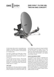
10W <strong>Ka</strong>-<strong>Band</strong> BUC<br />
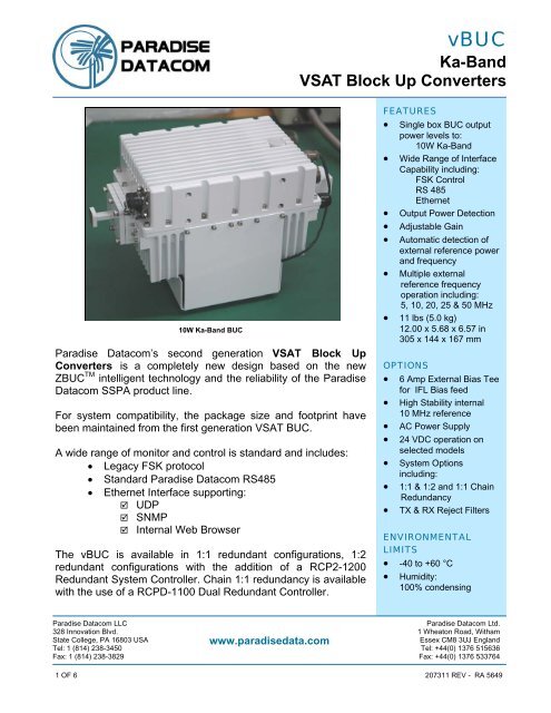
Paradise Datacom’s second generation <strong>VSAT</strong> <strong>Block</strong> <strong>Up</strong><br />
<strong>Converters</strong> is a completely new design based on the new<br />
ZBUC TM intelligent technology and the reliability of the Paradise<br />
Datacom SSPA product line.<br />
For system compatibility, the package size and footprint have<br />
been maintained from the first generation <strong>VSAT</strong> BUC.<br />
A wide range of monitor and control is standard and includes:<br />
• Legacy FSK protocol<br />
• Standard Paradise Datacom RS485<br />
• Ethernet Interface supporting:<br />
UDP<br />
SNMP<br />
Internal Web Browser<br />
The vBUC is available in 1:1 redundant configurations, 1:2<br />
redundant configurations with the addition of a RCP2-1200<br />
Redundant System Controller. Chain 1:1 redundancy is available<br />
with the use of a RCPD-1100 Dual Redundant Controller.<br />
FEATURES<br />
• Single box BUC output<br />
power levels to:<br />
10W <strong>Ka</strong>-<strong>Band</strong><br />
• Wide Range of Interface<br />
Capability including:<br />
FSK Control<br />
RS 485<br />
Ethernet<br />
• Output Power Detection<br />
• Adjustable Gain<br />
• Automatic detection of<br />
external reference power<br />
and frequency<br />
• Multiple external<br />
reference frequency<br />
operation including:<br />
5, 10, 20, 25 & 50 MHz<br />
• 11 lbs (5.0 kg)<br />
12.00 x 5.68 x 6.57 in<br />
305 x 144 x 167 mm<br />
OPTIONS<br />
• 6 Amp External Bias Tee<br />
for IFL Bias feed<br />
• High Stability internal<br />
10 MHz reference<br />
• AC Power Supply<br />
• 24 VDC operation on<br />
selected models<br />
• System Options<br />
including:<br />
• 1:1 & 1:2 and 1:1 Chain<br />
Redundancy<br />
• TX & RX Reject Filters<br />
ENVIRONMENTAL<br />
LIMITS<br />
• -40 to +60 °C<br />
• Humidity:<br />
100% condensing<br />
Paradise Datacom LLC<br />
Paradise Datacom Ltd.<br />
328 Innovation Blvd. 1 Wheaton Road, Witham<br />
State College, PA 16803 USA<br />
www.paradisedata.com<br />
Essex CM8 3UJ England<br />
Tel: 1 (814) 238-3450 Tel: +44(0) 1376 515636<br />
Fax: 1 (814) 238-3829 Fax: +44(0) 1376 533764<br />
1 OF 6 207311 REV - RA 5649
vBUC<br />
<strong>Ka</strong>-<strong>Band</strong><br />
<strong>VSAT</strong> <strong>Block</strong> <strong>Up</strong> <strong>Converters</strong><br />
PARAMETER MODEL NUMBER NOTES LIMITS UNITS<br />
Frequency Range 30.0 to 31.0 GHz<br />
Output Power @: Saturation/P 1dB<br />
(Typical/Guaranteed minimum)<br />
Power Requirements<br />
48 VDC Input<br />
@ max current draw<br />
<strong>Ka</strong>-<strong>Band</strong> Output Power Levels<br />
VBUCKA10AAXXXXX<br />
VBUCKA10AAXXXXX<br />
Gain<br />
70 dB<br />
24 VDC current<br />
5.0<br />
P sat / P 1dB<br />
40.0 / 39.0 (10 / 8) dBm (W)<br />
48 VDC current<br />
2.8 Amps<br />
Frequency <strong>Band</strong>s<br />
<strong>Band</strong> Frequency Plan* IF Input LO Frequency RF Output<br />
<strong>Ka</strong> Standard <strong>Ka</strong>-<strong>Band</strong> 1.0 - 2.0 MHz 29.0 GHz 30.0 - 31.0 GHz<br />
* Custom frequency plans available upon request.<br />
Local Oscillator Phase Noise<br />
Offset<br />
Guaranteed<br />
Max.<br />
<strong>Ka</strong>-<strong>Band</strong><br />
Typical<br />
Units<br />
10 Hz -30 -50 dBc/Hz<br />
100 Hz -60 -65 dBc/Hz<br />
1 KHz -65 -76 dBc/Hz<br />
10 KHz -75 -85 dBc/Hz<br />
100 KHz -90 -105 dBc/Hz<br />
1 MHz -90 -120 dBc/Hz<br />
2 OF 6 207311 REV - RA 5649
Specifications<br />
vBUC<br />
<strong>Ka</strong>-<strong>Band</strong><br />
<strong>VSAT</strong> <strong>Block</strong> <strong>Up</strong> <strong>Converters</strong><br />
PARAMETER NOTES LIMITS UNITS<br />
Gain Flatness<br />
Gain Slope<br />
Gain variation vs. Temperature<br />
full band<br />
per 40 MHz<br />
± 2.0<br />
± 0.75<br />
0 + 1.0<br />
Intermodulation Distortion 3dB back off relative to P 1dB -25 dBc<br />
Spurious<br />
In-<strong>Band</strong> Signal Related<br />
Close to Carrier Spurious (< 20 MHz)<br />
Local Oscillator<br />
Non-Signal Related<br />
-50<br />
-70<br />
-70<br />
-50<br />
dBc<br />
dBc<br />
dBm<br />
dBm<br />
Harmonics 2 nd harmonic measured at P 1dB -40 dBc<br />
Output Spectrum Low side Local Oscillator Non Inverted<br />
Input VSWR 1.43:1<br />
Output VSWR 1.67:1<br />
Noise Figure 15 dB<br />
Group Delay<br />
(per 40 MHz segment)<br />
Linear<br />
Parabolic<br />
Ripple<br />
0.02<br />
0.005<br />
1.0<br />
dB<br />
dB<br />
dB<br />
ns/MHz<br />
ns/MHz 2<br />
ns p-p<br />
User Adjustable Gain In 0.1 dB steps +15 dB<br />
Reference Input Frequency Diplexed on L-<strong>Band</strong> Input Connector 5, 10, 20, 25, 50 MHz MHz<br />
Reference Input Power Diplexed on L-<strong>Band</strong> Input Connector -10 to +5 dBm<br />
Input Voltage +48 VDC nominal +36 to +60 VDC<br />
FSK Communication 1<br />
Diplexed on L-<strong>Band</strong> Input<br />
Alarm Output<br />
Center Frequency<br />
Deviation<br />
Locking Range<br />
Input Power Range<br />
Start Tone Time<br />
Phase Lock Alarm<br />
Internal BUC Voltages<br />
BUC Current<br />
+48 or +24 VDC Input Voltage<br />
Case Temperature<br />
LNB Current<br />
Internal Reference Option 2<br />
Reference Frequency<br />
Freq. Stability over temperature range<br />
Aging per day<br />
Aging per year<br />
Frequency Accuracy<br />
Warm up time<br />
Internal Reference Phase Noise<br />
10 Hz<br />
100 Hz<br />
1 kHz<br />
10 kHz<br />
100 kHz<br />
1 FSK Communication protocol, document # 201410<br />
2 Internal reference option units will automatically detect and switch to an applied external reference.<br />
650<br />
+60<br />
+32.5<br />
-15 to -5<br />
10<br />
Form C Summary<br />
Contacts<br />
10<br />
< ±1 • 10 -8<br />
< ±1 • 10 -9<br />
< ±5 • 10 -8<br />
±1 • 10 -8<br />
20 minutes<br />
-120<br />
-140<br />
-145<br />
-152<br />
-155<br />
KHz<br />
KHz<br />
KHz<br />
dBm<br />
msec<br />
MHz<br />
< +1 • 10 -8<br />
dBc/Hz<br />
dBc/Hz<br />
dBc/Hz<br />
dBc/Hz<br />
dBc/Hz<br />
3 OF 6 207311 REV - RA 5649
vBUC<br />
<strong>Ka</strong>-<strong>Band</strong><br />
<strong>VSAT</strong> <strong>Block</strong> <strong>Up</strong> <strong>Converters</strong><br />
Interfaces<br />
Port<br />
J1<br />
J7<br />
J4<br />
J5<br />
J8<br />
Connector Description Details<br />
L <strong>Band</strong> Input IF, 10 MHz, FSK Input<br />
DC must be tapped off using<br />
external Bias Tee<br />
Type N<br />
female<br />
DC Input<br />
MS3102R18-4P<br />
Monitor & Control<br />
MS3112E14-18S<br />
Link Connector<br />
MS3112E12-10S<br />
Fan Voltage<br />
MS3112E8-3S<br />
+48 VDC<br />
Optional +24 VDC<br />
Serial Communication<br />
Serial Communication<br />
Serial Communication<br />
Summary Alarm Contacts<br />
Summary Alarm Contacts<br />
Summary Alarm Contacts<br />
TX Inhibit<br />
Ethernet<br />
Ethernet<br />
Ethernet<br />
Ethernet<br />
Ground<br />
Ground<br />
Ground<br />
Serial Override<br />
Ethernet Override<br />
Reserved<br />
Ground<br />
Ground<br />
+15 VDC for LNB<br />
Reserved<br />
Redundancy Switch Drive<br />
Link In<br />
Link Out<br />
Redundancy Switch Common<br />
V+<br />
V-<br />
A<br />
B<br />
C<br />
D<br />
U<br />
R<br />
L<br />
B<br />
F<br />
D<br />
J<br />
H<br />
G<br />
C<br />
A<br />
E<br />
K<br />
M<br />
S<br />
N<br />
J<br />
C<br />
H<br />
A<br />
B<br />
G<br />
E<br />
F<br />
K<br />
A<br />
B<br />
+ VDC<br />
+ VDC<br />
- VDC<br />
- VDC<br />
RS-485 (-)<br />
RS-485 (+)<br />
Isolated Ground<br />
Form C - Closed on Fault<br />
Form C - Common<br />
Form C - Open on Fault<br />
Ground Enable TX<br />
TX -<br />
TX +<br />
RX -<br />
RX +<br />
Chassis Ground<br />
Chassis Ground<br />
Chassis Ground<br />
Ground resets to Serial Comms<br />
Ground resets to Ethernet Comms<br />
Closure to Ground<br />
Ground<br />
Ground<br />
Current Sensed +15 VDC<br />
+15 VDC @ 1A<br />
+48 or +24 Current Sink<br />
+48 or +24 VDC (Vin+)<br />
+48 or +24 VDC<br />
Return<br />
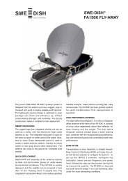
Universal M&C Software<br />
The Paradise Datacom Universal Monitor & Control<br />
software provides a remote view of the state of the<br />
vBUC via a web browser.<br />
The user may adjust the attenuation of the vBUC and<br />
mute/unmute the unit. In addition, the web-based<br />
status screen shows the fault condition, mute state,<br />
current and temperature.<br />
4 OF 6 207311 REV - RA 5649
vBUC<br />
<strong>Ka</strong>-<strong>Band</strong><br />
<strong>VSAT</strong> <strong>Block</strong> <strong>Up</strong> <strong>Converters</strong><br />
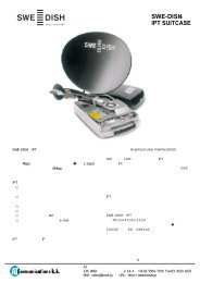
AC Power Supply option<br />
The vBUC is available with an optional AC Power<br />
Supply, which attaches to the top of the BUC,<br />
opposite the fan. An optional stand-alone mounting<br />
assembly is also available.<br />
The AC Power Supply provides up to 500 Watts of<br />
power at 48VDC output.<br />
Input power requirements: 85-265VAC, 47-63Hz.<br />
Pin-outs<br />
A B C D<br />
AC Input Line GND Neutral --<br />
DC Output +48V +48V<br />
48V<br />
Return<br />
48V<br />
Return<br />
MODEL: XXXXXXXXXXXX<br />
S/N: XXXX<br />
P/N: LXXXXXX-X<br />
Outline Drawing,<br />
C-<strong>Band</strong> vBUC with<br />
AC Power Supply<br />
option<br />
5 OF 6 207311 REV - RA 5649
Part Number Configuration<br />
vBUC<br />
<strong>Ka</strong>-<strong>Band</strong><br />
<strong>VSAT</strong> <strong>Block</strong> <strong>Up</strong> <strong>Converters</strong><br />
V B<br />
U<br />
C K<br />
A<br />
1 0 A<br />
<strong>Band</strong><br />
KA - <strong>Ka</strong>-<strong>Band</strong><br />
Power Level<br />
(in Watts)<br />
<strong>Ka</strong>-<strong>Band</strong><br />
10<br />
Frequency Sub <strong>Band</strong><br />
<strong>Ka</strong>-<strong>Band</strong><br />
A - 30.0 - 31.0 GHz<br />
Input Voltage<br />
A = +48 V<br />
B = +24 V<br />
Configuration Modifier<br />
XXX = Standard<br />
WXX = Waveguide Isolator<br />
System Configuration Options<br />
X = Single Thread (Stand Alone)<br />
See Drawing Number 203614 for redundant system<br />
configurations.<br />
Reference Signal<br />
X = Standard External Reference<br />
R = Internal 10 MHz Reference Oscillator<br />
Input Power Configuration<br />
X = Input Voltage on Circular Connector (Standard)<br />
A* = AC Power Supply mounted to BUC<br />
B* = AC Power Supply with DC connectors only<br />
C* = AC Power Supply with custom-length DC cable<br />
T* = External IFL Bias Tee<br />
* Available with +48V Input Voltage only<br />
Specifications within this document are subject to change without notice.<br />
6 OF 6 207311 REV - RA 5649