Inkjet printing of polyurethane colloidal suspensions
Inkjet printing of polyurethane colloidal suspensions
Inkjet printing of polyurethane colloidal suspensions

Create successful ePaper yourself
Turn your PDF publications into a flip-book with our unique Google optimized e-Paper software.
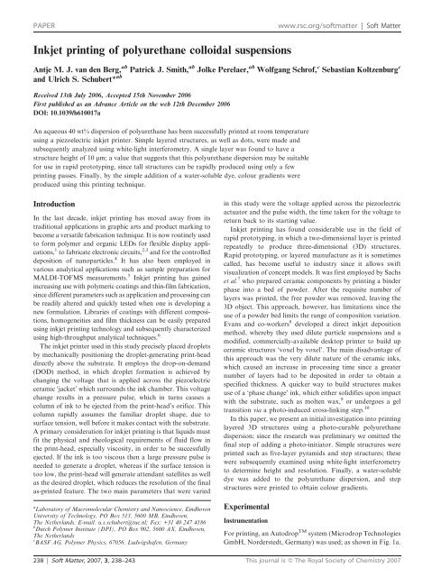
PAPER<br />
www.rsc.org/s<strong>of</strong>tmatter | S<strong>of</strong>t Matter<br />
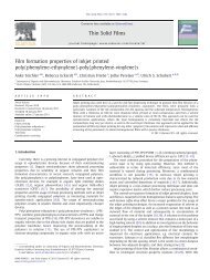
<strong>Inkjet</strong> <strong>printing</strong> <strong>of</strong> <strong>polyurethane</strong> <strong>colloidal</strong> <strong>suspensions</strong><br />
Antje M. J. van den Berg, ab Patrick J. Smith, ab Jolke Perelaer, ab Wolfgang Schr<strong>of</strong>, c Sebastian Koltzenburg c<br />
and Ulrich S. Schubert* ab<br />
Received 13th July 2006, Accepted 15th November 2006<br />
First published as an Advance Article on the web 12th December 2006<br />
DOI: 10.1039/b610017a<br />
An aqueous 40 wt% dispersion <strong>of</strong> <strong>polyurethane</strong> has been successfully printed at room temperature<br />
using a piezoelectric inkjet printer. Simple layered structures, as well as dots, were made and<br />
subsequently analyzed using white-light interferometry. A single layer was found to have a<br />
structure height <strong>of</strong> 10 mm; a value that suggests that this <strong>polyurethane</strong> dispersion may be suitable<br />
for use in rapid prototyping, since tall structures can be rapidly produced using only a few<br />
<strong>printing</strong> passes. Finally, by the simple addition <strong>of</strong> a water-soluble dye, colour gradients were<br />
produced using this <strong>printing</strong> technique.<br />
Introduction<br />
In the last decade, inkjet <strong>printing</strong> has moved away from its<br />
traditional applications in graphic arts and product marking to<br />
become a versatile fabrication technique. It is now routinely used<br />
to form polymer and organic LEDs for flexible display applications,<br />
1 to fabricate electronic circuits, 2,3 and for the controlled<br />
deposition <strong>of</strong> nanoparticles. 4 It has also been employed in<br />
various analytical applications such as sample preparation for<br />
MALDI-TOFMS measurements. 5 <strong>Inkjet</strong> <strong>printing</strong> has gained<br />
increasing use with polymeric coatings and thin-film fabrication,<br />
since different parameters such as application and processing can<br />
be readily altered and quickly tested when one is developing a<br />
new formulation. Libraries <strong>of</strong> coatings with different compositions,<br />
homogeneities and film thickness can be easily prepared<br />
using inkjet <strong>printing</strong> technology and subsequently characterized<br />
using high-throughput analytical techniques. 6<br />
The inkjet printer used in this study precisely placed droplets<br />
by mechanically positioning the droplet-generating print-head<br />
directly above the substrate. It employs the drop-on-demand<br />
(DOD) method, in which droplet formation is achieved by<br />
changing the voltage that is applied across the piezoelectric<br />
ceramic ‘jacket’ which surrounds the ink chamber. This voltage<br />
change results in a pressure pulse, which in turns causes a<br />
column <strong>of</strong> ink to be ejected from the print-head’s orifice. This<br />
column rapidly assumes the familiar droplet shape, due to<br />
surface tension, well before it makes contact with the substrate.<br />
A primary consideration for inkjet <strong>printing</strong> is that liquids must<br />
fit the physical and rheological requirements <strong>of</strong> fluid flow in<br />
the print-head, especially viscosity, in order to be successfully<br />
ejected. If the ink is too viscous then a large pressure pulse is<br />
needed to generate a droplet, whereas if the surface tension is<br />
too low, the print-head will generate attendant satellites as well<br />
as the desired droplet, which reduces the resolution <strong>of</strong> the final<br />
as-printed feature. The two main parameters that were varied<br />
a Laboratory <strong>of</strong> Macromolecular Chemistry and Nanoscience, Eindhoven<br />
University <strong>of</strong> Technology, PO Box 513, 5600 MB, Eindhoven,<br />
The Netherlands. E-mail: u.s.schubert@tue.nl; Fax: +31 40 247 4186<br />
b Dutch Polymer Institute (DPI), PO Box 902, 5600 AX, Eindhoven,<br />
The Netherlands<br />
c BASF AG, Polymer Physics, 67056, Ludwigshafen, Germany<br />
in this study were the voltage applied across the piezoelectric<br />
actuator and the pulse width, the time taken for the voltage to<br />
return back to its starting value.<br />
<strong>Inkjet</strong> <strong>printing</strong> has found considerable use in the field <strong>of</strong><br />
rapid prototyping, in which a two-dimensional layer is printed<br />
repeatedly to produce three-dimensional (3D) structures.<br />
Rapid prototyping, or layered manufacture as it is sometimes<br />
called, has become useful to industry since it allows swift<br />
visualization <strong>of</strong> concept models. It was first employed by Sachs<br />
et al. 7 who prepared ceramic components by <strong>printing</strong> a binder<br />
phase into a bed <strong>of</strong> powder. After the requisite number <strong>of</strong><br />
layers was printed, the free powder was removed, leaving the<br />
3D object. This approach, however, has limitations since the<br />
use <strong>of</strong> a powder bed limits the range <strong>of</strong> composition variation.<br />
Evans and co-workers 8 developed a direct inkjet deposition<br />
method, whereby they used dilute particle <strong>suspensions</strong> and a<br />
modified, commercially-available desktop printer to build up<br />
ceramic structures ‘voxel by voxel’. The main disadvantage <strong>of</strong><br />
this approach was the very dilute nature <strong>of</strong> the ceramic inks,<br />
which caused an increase in processing time since a greater<br />
number <strong>of</strong> layers had to be deposited in order to obtain a<br />
specified thickness. A quicker way to build structures makes<br />
use <strong>of</strong> a ‘phase change’ ink, which either solidifies upon impact<br />
with the substrate, such as molten wax, 9 or undergoes a gel<br />
transition via a photo-induced cross-linking step. 10<br />
In this paper, we present an initial investigation into <strong>printing</strong><br />
layered 3D structures using a photo-curable <strong>polyurethane</strong><br />
dispersion; since the research was preliminary we omitted the<br />
final step <strong>of</strong> adding a photo-initiator. Simple structures were<br />
printed such as five-layer pyramids and step structures; these<br />
were subsequently examined using white-light interferometry<br />
to determine height and resolution. Finally, a water-soluble<br />
dye was added to the <strong>polyurethane</strong> dispersion, and step<br />
structures were printed to obtain colour gradients.<br />
Experimental<br />
Instrumentation<br />
For <strong>printing</strong>, an Autodrop TM system (Microdrop Technologies<br />
GmbH, Norderstedt, Germany) was used; as shown in Fig. 1a.<br />
238 | S<strong>of</strong>t Matter, 2007, 3, 238–243 This journal is ß The Royal Society <strong>of</strong> Chemistry 2007
found to be 45u. The dye used to make the colour gradients<br />
was Disperse Red (Aldrich).<br />
Results and discussion<br />
Fig. 1 (a) A photograph <strong>of</strong> the Autodrop TM printer system, which<br />
was used in these experiments; it is equipped with (b) a heatable printhead<br />
(Microdrop Technologies GmbH).<br />
It is equipped with a print-head that can move in the X, Y<br />
and Z directions, and a platen, onto which substrates were<br />
placed. All <strong>printing</strong> was performed at room temperature. The<br />
Autodrop TM system has a working space <strong>of</strong> 200 6 200 6<br />
80 mm, a positioning accuracy <strong>of</strong> 3 mm and has a stroboscopic<br />
video camera, which is used to determine the correct<br />
conditions for droplet formation. The print-head is an MD-<br />
H-712-PH dispenser, which has a nozzle diameter <strong>of</strong> 100 mm; a<br />
typical example is illustrated in Fig. 1b.<br />
The Autodrop TM printer allows the user to determine the<br />
number <strong>of</strong> droplets to be deposited in both the X and Y<br />
directions, and to ascribe a value to the spacing between the<br />
centres <strong>of</strong> each droplet; the so-called dot-spacing. Continuous<br />
features are formed by making the dot-spacing between the<br />
droplet’s centres small enough so that they merge on the<br />
surface. 11 The structure’s surface and the height <strong>of</strong> the inkjet<br />
printed areas were characterized using a white-light interferometer<br />
(Nanotech Zoomsurf 3D, Fogale, France), which<br />
has a vertical resolution <strong>of</strong> 7 nm and a horizontal resolution <strong>of</strong><br />
150 nm. A 56 objective was used for all measurements.<br />
Finally, UV-VIS spectra were obtained using a UV-VIS<br />
spectrophotometer (Flashscan 530, Analytik Jena, Germany.)<br />
Materials<br />
An aqueous <strong>polyurethane</strong> dispersion (LR 9005, BASF-AG,<br />
Ludwigshafen, Germany) with an approximate solid content<br />
<strong>of</strong> 40 wt% was used. The <strong>polyurethane</strong> had an average particle<br />
size <strong>of</strong> 100–200 nm, a molecular weight <strong>of</strong> approximately<br />
1600 g mol 21 , and its dispersion had a viscosity <strong>of</strong> 20 mPa s<br />
at 23 uC. Microscopic slides, 3 6 1 inch (Marienfeld, Lauda-<br />
Königsh<strong>of</strong>en, Germany) were used as the substrates. These<br />
were ultra-sonicated for 10 minutes in acetone. They were then<br />
rinsed with acetone before being cleaned with sodium dodecyl<br />
sulphate solution and washed with de-ionized water to remove<br />
the soap. They were then treated with isopropanol vapour in a<br />
reflux setup to remove the water and dried under a flow <strong>of</strong> air.<br />
Finally, to remove any organic contamination, the substrates<br />
were treated in a UV–ozone photo-reactor (UVP PR-100,<br />
Upland, CA) for 20 minutes. The contact angle that the<br />
aqueous <strong>polyurethane</strong> dispersion made with the cleaned glass<br />
slide was measured (OCA 30, Dataphysics, Germany) and<br />
The first part <strong>of</strong> our investigation was concerned with<br />
obtaining the optimal jetting conditions for the 40 wt%<br />
<strong>polyurethane</strong> dispersion, and determining if the <strong>polyurethane</strong><br />
dispersion needed diluting. In order to print structures with<br />
appreciable heights, one can either use an ink with a high<br />
solids content, 9 since this requires a smaller number <strong>of</strong> passes,<br />
or one can perform a larger number <strong>of</strong> passes using a more<br />
dilute ink; 12 this choice is dependent upon the type <strong>of</strong> inkjet<br />
printer that is being used. Here, we adopted the approach <strong>of</strong><br />
using the high-solids ink, since the as-received dispersion was<br />
40 wt% and the Autodrop TM system is a piezoelectric inkjet<br />
printer, which is capable <strong>of</strong> dealing with inks with viscosities in<br />
the range <strong>of</strong> 0.5–20 mPa s. 13 The viscosity <strong>of</strong> the as-received<br />
dispersion was 20 mPa s, which is at the top <strong>of</strong> the printability<br />
range using piezoelectric inkjet <strong>printing</strong>. 13 This value was<br />
expected since viscosity is known to increase with increased<br />
solids loading. 9 A 20 wt% dispersion was also prepared, by<br />
simply diluting the as-received <strong>polyurethane</strong> suspension, in<br />
case the 40 wt% dispersion could not be printed. A further<br />
consideration was particle size since the ink was composed <strong>of</strong><br />
particles suspended in an aqueous carrier, i.e. it was not a<br />
solution. However, the average particle size <strong>of</strong> the dispersion<br />
was 100–200 nm, several orders <strong>of</strong> magnitude smaller than the<br />
100 mm nozzle, and the dispersion itself was not seen to<br />
agglomerate. The anticipated problem <strong>of</strong> nozzle clogging did<br />
not occur.<br />
Both dispersions were printed at room temperature using the<br />
same pulse width (28 ms), frequency (200 Hz), and dot-spacing<br />
(50 mm in X and 100 mm in Y). The only parameter that<br />
needed to be changed was the voltage, which was increased<br />
from 90 V (for the 20 wt% ink) to 96 V (for 40 wt%). For both<br />
concentrations, no difference in drop formation was observed;<br />
that is good, well-formed droplets were seen to be produced.<br />
The inset <strong>of</strong> Fig. 2 shows a typical droplet produced using the<br />
40 wt% dispersion. The increase in voltage, which was needed<br />
to print the ink with the higher solids loading, was also found<br />
to be necessary by Seerden et al., 9 who used 70 V for a 30wt%<br />
solution compared to 80 V for a 40 wt% ink. It is known that<br />
increased building rates can be achieved by operating the<br />
print-head at higher frequencies, since frequency directly<br />
influences the rate <strong>of</strong> droplet production. 9 Future research<br />
using this material for rapid prototyping could investigate the<br />
effect <strong>of</strong> an increased build rate; however, the scope <strong>of</strong> this<br />
research was concerned with investigating the printability <strong>of</strong><br />
the <strong>polyurethane</strong> dispersion, and therefore frequency was kept<br />
constant.<br />
Fig. 2 shows the pr<strong>of</strong>iles obtained from printed, singlelayered<br />
films <strong>of</strong> the 20 wt% and 40 wt% dispersions. It can<br />
clearly be seen that the film obtained from the 40 wt%<br />
dispersion produced a smooth pr<strong>of</strong>ile, whereas the film<br />
obtained from the 20 wt% dispersion produced an irregular<br />
pr<strong>of</strong>ile that showed a greater variation in height. It is suggested<br />
that the pr<strong>of</strong>ile observed for the 20 wt% solution is due to it<br />
being more dilute. Furthermore, the dimple seen in the middle<br />
This journal is ß The Royal Society <strong>of</strong> Chemistry 2007 S<strong>of</strong>t Matter, 2007, 3, 238–243 | 239
Fig. 2 Two pr<strong>of</strong>iles obtained by white-light interferometry <strong>of</strong> singlelayered<br />
films printed with 20 wt% and 40 wt% <strong>polyurethane</strong><br />
dispersions. The inset shows an image <strong>of</strong> a typical droplet <strong>of</strong> the<br />
40 wt% dispersion produced by the inkjet printer.<br />
<strong>of</strong> the 20 wt% solution may possibly be a consequence <strong>of</strong> the<br />
preferential deposition <strong>of</strong> suspended material towards a drying<br />
feature’s boundary, which was reported by Deegan et al. 14<br />
Certainly, it is fair to assume that for the 20 wt% solution more<br />
water has to evaporate in order for the feature to dry.<br />
Therefore, there is a greater propensity for material to migrate<br />
during drying, for the more dilute solution.<br />
On account <strong>of</strong> its obtained pr<strong>of</strong>ile and printability, it was<br />
decided to use the 40 wt% dispersion for further experiments.<br />
Subsequently, a series <strong>of</strong> dots <strong>of</strong> the 40 wt% <strong>polyurethane</strong><br />
dispersion was printed in order to observe individual<br />
behaviour. A typical sequence is illustrated in Fig. 3. The<br />
average height <strong>of</strong> each individual deposit was measured as<br />
being approximately 3 mm, which suggests that it may be<br />
suitable for rapid prototyping, where the ability to form thick<br />
layers quickly is desirable. This value <strong>of</strong> height was attributed<br />
to the high contact angle that the dispersion formed with the<br />
cleaned substrates. Clearly a lower contact angle would<br />
have led to a decrease in droplet height and a broader base.<br />
The height <strong>of</strong> the individual droplets is lower than for the<br />
corresponding films. This was expected as dot-spacing, which<br />
is the distance between the centres <strong>of</strong> two deposited droplets,<br />
influences structure height. 15 The more dot-spacing is<br />
decreased, the greater the height <strong>of</strong> the printed structure.<br />
The decrease in volume was measured for the deposited<br />
droplets, using white-light interferometry, and was found to be<br />
43%. The dimple apparent in the centre <strong>of</strong> each dried droplet is<br />
attributed to drying.<br />
In order to produce functional structures, the individual<br />
<strong>polyurethane</strong> droplets were printed in such a way that the<br />
descending droplet partially overlapped with the preceding<br />
droplet to produce linear features. Well-defined lines with a<br />
width <strong>of</strong> 224 ¡ 12 mm were obtained on the as-cleaned glass<br />
slides using a dot-spacing <strong>of</strong> 100 mm. By <strong>printing</strong> a sequence <strong>of</strong><br />
lines whose inter-line spacing corresponded to the dot-spacing,<br />
homogeneous films with an average height <strong>of</strong> 2.50 ¡ 0.2 mm<br />
were obtained. Ten layers were printed on top <strong>of</strong> each other,<br />
which resulted in a film thickness value <strong>of</strong> 59 ¡ 22.6 mm.<br />
However, these ten-layered films were not homogeneous since<br />
successive layers were deposited on top <strong>of</strong> earlier layers that<br />
had not thoroughly dried.<br />
Therefore, in order to prepare a well-defined thickness<br />
gradient within one structure, a drying step <strong>of</strong> 5 minutes was<br />
required before <strong>printing</strong> the next layer. It is worth commenting<br />
Fig. 3 An image obtained by white-light interferometry <strong>of</strong> a sequence <strong>of</strong> single dots <strong>of</strong> 40 wt% <strong>polyurethane</strong> dispersion. The inset shows their<br />
associated pr<strong>of</strong>iles, which demonstrates their height and suggests the suitability <strong>of</strong> this dispersion for rapid prototyping.<br />
240 | S<strong>of</strong>t Matter, 2007, 3, 238–243 This journal is ß The Royal Society <strong>of</strong> Chemistry 2007
that all <strong>printing</strong> was performed at room temperature and the<br />
time <strong>of</strong> this drying step could be reduced, or removed, by<br />
heating the platen <strong>of</strong> the printer. The as-obtained thickness<br />
gradient resembled a step structure, i.e. the base layer was the<br />
largest in terms <strong>of</strong> area and each subsequent, and higher, step<br />
had a reduced area. An initial 6 6 6 mm square base was<br />
printed and allowed to dry, and then a second 4.5 6 6mm<br />
rectangular layer was printed. Two more step-like layers <strong>of</strong> 3 6<br />
6 mm and 1.5 6 6 mm, respectively, were printed to produce a<br />
thickness gradient. (This process was done repeatedly and was<br />
found to be highly reproducible.) Fig. 4 shows a typical<br />
thickness gradient; each constituent step is composed <strong>of</strong> a<br />
single layer, i.e. one <strong>printing</strong> pass produced the layer, and can<br />
be clearly seen. The thickness <strong>of</strong> each step is as follows:<br />
layer 1 = 12.5 ¡ 3.53 mm, layer 2 = 13.0 ¡ 4.94 mm, layer 3 =<br />
8.50 ¡ 2.82 mm and layer 4 = 6.00 ¡ 8.48 mm. The decrease in<br />
layer thickness can be explained by the fact that the previous<br />
layer is partially dissolved by the layer printed on top <strong>of</strong> it. For<br />
the first layer this effect does not count since this one is printed<br />
directly on the glass substrate. It can also be seen that the<br />
highest step displays the greatest variation in thickness and, as<br />
can be seen from Fig. 4, it has a pronounced slope towards the<br />
back <strong>of</strong> the step structure. This slope may be a consequence <strong>of</strong><br />
the combined ‘settling’ <strong>of</strong> the three underlying layers.<br />
Using this step-building method, a square-based, pyramidlike<br />
structure was subsequently obtained by <strong>printing</strong> five layers<br />
on top <strong>of</strong> each other; again each layer was produced using a<br />
single pass <strong>of</strong> the print-head and was allowed 5 minutes to dry.<br />
The base was 10 6 10 mm and the area <strong>of</strong> each subsequent<br />
step decreased by 2 mm per side; with the uppermost layer<br />
being 2 6 2 mm. The height <strong>of</strong> the pyramid was determined by<br />
white-light interferometry and found to be 87 mm, with each<br />
step having the following thicknesses: layer 1 = 14.5 ¡<br />
3.04 mm, layer 2 = 17.5 ¡ 1.62 mm, layer 3 = 9.55 ¡ 2.54 mm,<br />
layer 4 = 13.7 ¡ 4.03 mm and layer 5 = 25.5 ¡ 7.99 mm. The<br />
resultant structure, as shown in Fig. 5, has distinct, welldefined<br />
steps; the plan view (Fig. 5a) shows each layer clearly.<br />
For the 3D representation (Fig. 5b), the edge definition is<br />
slightly ‘sharper’ at the front <strong>of</strong> the structure then at the back.<br />
This is also visible in the section (Fig. 5c) whereby the edges at<br />
the left <strong>of</strong> the picture are sharper and more distinct then those<br />
on the right. This difference in edge pr<strong>of</strong>ile is explained as<br />
being due to the direction <strong>of</strong> print-head travel. The material at<br />
the left hand side <strong>of</strong> each <strong>of</strong> the layers, shown in the section<br />
(Fig. 5c), was printed last. Therefore, this material had more<br />
time to dry, since the print-head travelled from right to left,<br />
and subsequently began building a new layer on the right hand<br />
side <strong>of</strong> the previously printed layer.<br />
Polyurethane has been used in the preparation <strong>of</strong> microcontact<br />
stamps and in other patterning applications. 16 It may<br />
be possible that, with the use <strong>of</strong> specially prepared surfaces,<br />
micro-contact stamps could be produced from <strong>polyurethane</strong><br />
using inkjet <strong>printing</strong>. Although there is a clear increase in<br />
height for each layer that is printed, stamps produced using<br />
inkjet <strong>printing</strong> and unprepared surfaces are unlikely to gain<br />
acceptance on account <strong>of</strong> their dimensions being a couple <strong>of</strong><br />
orders <strong>of</strong> magnitude larger.<br />
The final part <strong>of</strong> our investigation involved the fabrication<br />
<strong>of</strong> colour gradients, which were obtained by adding 0.5 wt%<br />
Disperse Red to the <strong>polyurethane</strong> dispersion. Thickness<br />
gradients, similar to those shown in Fig. 4 but composed <strong>of</strong><br />
five layers, were printed. Fig. 6 illustrates two <strong>of</strong> the colour<br />
gradients that were prepared. The most intense red colour<br />
was seen in the area that was composed <strong>of</strong> five layers. It is<br />
suggested that these colour gradients could be used as<br />
colour filters 17,18 for creating two-dimensional gradients on a<br />
substrate that has been coated with a photo-curable material.<br />
19,20 The UV-VIS spectra <strong>of</strong> the films are shown in Fig. 7.<br />
It can be seen that <strong>polyurethane</strong> and glass exhibit similar<br />
absorbance behaviour in the visible spectrum to that <strong>of</strong> glass,<br />
Fig. 4 An image and a pr<strong>of</strong>ile, obtained by white-light interferometry, <strong>of</strong> a thickness gradient produced by <strong>printing</strong> a structure composed <strong>of</strong> welldefined<br />
steps <strong>of</strong> 40 wt% <strong>polyurethane</strong> dispersion.<br />
This journal is ß The Royal Society <strong>of</strong> Chemistry 2007 S<strong>of</strong>t Matter, 2007, 3, 238–243 | 241
Fig. 5 An image and a pr<strong>of</strong>ile, obtained by white-light interferometry, <strong>of</strong> a pyramid-like structure <strong>of</strong> 40 wt% <strong>polyurethane</strong> dispersion obtained<br />
from <strong>printing</strong> successively smaller layers.<br />
whereas the trace for glass/<strong>polyurethane</strong>/Disperse Red displays<br />
a clear absorbance in the blue–green part <strong>of</strong> the visible<br />
spectrum.<br />
Conclusions<br />
An aqueous 40 wt% dispersion <strong>of</strong> <strong>polyurethane</strong> has been<br />
successfully printed at room temperature using a piezoelectric<br />
inkjet printer. Simple layered structures such as pyramids and<br />
step-structures, as well as dots, were printed. These were<br />
subsequently analyzed using white-light interferometry. The<br />
height <strong>of</strong> the individual dots was found to be 3 mm, whereas<br />
a single-layered film and the component layers <strong>of</strong> a step<br />
structure were found to have heights <strong>of</strong> about 10 mm. This<br />
value in height, for the film and layers, was attributed to<br />
dot-spacing, which is the distance between the centres <strong>of</strong><br />
deposited droplets. This value suggests that this <strong>polyurethane</strong><br />
dispersion may be suitable for use in rapid prototyping, since<br />
Fig. 6 A photograph <strong>of</strong> the colour gradients produced by the<br />
addition <strong>of</strong> 0.5 wt% Disperse Red to the 40 wt% <strong>polyurethane</strong><br />
dispersion.<br />
Fig. 7 UV-VIS spectra <strong>of</strong> the printed 40 wt% <strong>polyurethane</strong> films with<br />
and without the addition <strong>of</strong> 0.5 wt% Disperse Red.<br />
242 | S<strong>of</strong>t Matter, 2007, 3, 238–243 This journal is ß The Royal Society <strong>of</strong> Chemistry 2007
tall structures can be rapidly produced using only a few<br />
<strong>printing</strong> passes. A possible drawback in using this dispersion<br />
could be the 5 minute drying time that was used for each<br />
printed step. However, this could be reduced or even removed<br />
if the dispersion was printed at higher temperatures. Finally,<br />
by the simple addition <strong>of</strong> a water-soluble dye, colour gradients<br />
were produced using this <strong>printing</strong> technique. As expected, a<br />
more intense hue was seen in those areas that contained more<br />
layers. This suggests that this <strong>polyurethane</strong> dispersion could be<br />
used in the preparation <strong>of</strong> colour filters.<br />
Acknowledgements<br />
The authors would like to thank BASF-AG for their<br />
stimulating discussion and financial support.<br />
References<br />
1 B. J. de Gans, P. C. Duineveld and U. S. Schubert, Adv. Mater.,<br />
2004, 16, 203.<br />
2 S. Holdcr<strong>of</strong>t, Adv. Mater., 2001, 13, 1753.<br />
3 P. J. Smith, D.-Y. Shin, J. E. Stringer, H. Reis and B. Derby,<br />
J. Mater. Sci., 2006, 41, 4153.<br />
4 P. Calvert, Chem. Mater., 2001, 13, 3299.<br />
5 M. A. R. Meier, B. J. de Gans, A. M. J. van den Berg and<br />
U. S. Schubert, Rapid Commun. Mass Spectrom., 2003, 17, 2349.<br />
6 S. Schmatloch, H. Bach, R. A. T. M. van Benthem and<br />
U. S. Schubert, Macromol. Rapid Commun., 2004, 25, 95.<br />
7 E. M. Sachs, M. Cima, P. Williams, D. Bracazio and J. Cornie,<br />
J. Eng. Ind., 1992, 114, 481.<br />
8 J. H. Song, M. J. Edirisinghe and J. R. G. Evans, J. Am. Ceram.<br />
Soc., 1999, 82, 3374.<br />
9 K. A. M. Seerden, N. Reis, J. R. G. Evans, P. S. Grant,<br />
J. W. Holloran and B. Derby, J. Am. Ceram. Soc., 2001, 84, 2514.<br />
10 J. Stampfl and R. Liska, Macromol. Chem. Phys., 2005, 206,<br />
1253.<br />
11 E. Tekin, B. J. de Gans and U. S. Schubert, J. Mater. Chem., 2004,<br />
14, 2627.<br />
12 M. Mott, J.-H. Song and J. R. Evans, J. Am. Ceram. Soc., 1999,<br />
82, 1653.<br />
13 http://www.microdrop.de/wDeutsch/products/md_series.shtml (last<br />
accessed on September 13th 2006).<br />
14 R. D. Deegan, O. Bakajin, T. F. Dupont, G. Huber, S. R. Nagel<br />
and T. A. Witten, Nature, 1997, 389, 827.<br />
15 E. Tekin, E. Holder, V. Marin, B. J. de Gans and U. S. Schubert,<br />
Macromol. Rapid Commun., 2005, 26, 293.<br />
16 Y. Xia, M. Mrksich, E. Kim and G. M. Whitesides, J. Am. Chem.<br />
Soc., 1995, 117, 9576.<br />
17 C.-J. Chang, S.-J. Chang, K.-C. Shih and F.-L. Pan, J. Polym. Sci.,<br />
Part B: Polym. Phys., 2005, 43, 3337.<br />
18 H.-S. Koo, P.-C. Pan, T. Kawai, M. Chen, F.-M. Wu, Y.-T. Liu<br />
and S.-J. Chang, Appl. Phys. Lett., 2006, 88, 11908.<br />
19 J. C. Meredith, A. P. Smith, A. Karim and E. J. Amis,<br />
Macromolecules, 2000, 33, 9747.<br />
20 J. C. Meredith, A. Karim and E. J. Amis, Macromolecules, 2000,<br />
33, 5760.<br />
This journal is ß The Royal Society <strong>of</strong> Chemistry 2007 S<strong>of</strong>t Matter, 2007, 3, 238–243 | 243