MT-4R and MT-4D P25 Digital and Analog Radio Systems - Daniels ...
MT-4R and MT-4D P25 Digital and Analog Radio Systems - Daniels ...
MT-4R and MT-4D P25 Digital and Analog Radio Systems - Daniels ...

Create successful ePaper yourself
Turn your PDF publications into a flip-book with our unique Google optimized e-Paper software.
Chapter 6: <strong>Radio</strong> System Components 39<br />
Channel Selection<br />
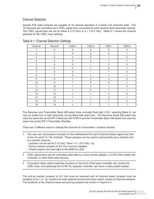
<strong>Daniels</strong> <strong>P25</strong> radio modules are capable of 16 channel operation in 2 banks (32 channels total). The<br />
16 channels are controlled via 4 CSEL signal lines connected to each receiver <strong>and</strong> transmitter module.<br />
The CSEL signal lines are set as either a 0 (0 Vdc) or a 1 (+9.5 Vdc). Table 6-1 shows the channel<br />
selected for the CSEL input settings.<br />
Table 6-1: Channel Selection Settings<br />
Channel Decimal CSEL3 CSEL2 CSEL1 CSEL0<br />
1 0 0 0 0 0<br />
2 1 0 0 0 1<br />
3 2 0 0 1 0<br />
4 3 0 0 1 1<br />
5 4 0 1 0 0<br />
6 5 0 1 0 1<br />
7 6 0 1 1 0<br />
8 7 0 1 1 1<br />
9 8 1 0 0 0<br />
10 9 1 0 0 1<br />
11 10 1 0 1 0<br />
12 11 1 0 1 1<br />
13 12 1 1 0 0<br />
14 13 1 1 0 1<br />
15 14 1 1 1 0<br />
16 15 1 1 1 1<br />
The Receiver <strong>and</strong> Transmitter Bank A/B select lines normally fl oat high (+5V), selecting Bank A, but<br />
may be pulled low or high externally via the Bank A/B select line. The Receiver Bank A/B select line<br />
uses the same line as the <strong>MT</strong>-3 Receiver ISO COR K <strong>and</strong> the Transmitter Bank A/B select line uses the<br />
same line as the <strong>MT</strong>-3 Transmitter St<strong>and</strong>by.<br />
There are 3 different ways to change the channel of a transmitter / receiver module:<br />
1 The user can set jumpers mounted on the motherboard for each Channel Select signal line (Set<br />
of four for each Tx / Rx module). These jumpers can be used to permanently set a subrack slot<br />
at a specifi c channel.<br />
- Jumpers can be set for 0 (0 Vdc) “down” or 1 (9.5 Vdc) “up”<br />
- Pull-up resistor jumpers to 9.5 Vdc must be installed<br />
- These jumpers are read right to left (MSD to LSD)<br />
2 CSEL signal lines can be controlled externally by a tone remote adapter, a CI-RC-4M multiple link<br />
controller, or other third party devices.<br />
3 16 position rotary select switches mounted on the front of the base controller can control the<br />
CSEL lines, <strong>and</strong> optionally the CI-RC-4L repeater controller can have a rotary switch added.<br />
The pull-up resistor jumpers to 9.5 Vdc must be removed <strong>and</strong> all channel select jumpers must be<br />
installed in the 1 or “up” position for both external control <strong>and</strong> rotary switch control of channel selection.<br />
The locations of the channel select <strong>and</strong> pull-up jumpers are shown in Figure 6-3.<br />
UG-001 <strong>Daniels</strong> <strong>MT</strong>-<strong>4R</strong> <strong>and</strong> <strong>MT</strong>-<strong>4D</strong> <strong>Radio</strong> <strong>Systems</strong><br />
www.danelec.com<br />
User<br />
Guide