Igneous Structures and Field Relationships - Faculty web pages
Igneous Structures and Field Relationships - Faculty web pages
Igneous Structures and Field Relationships - Faculty web pages

Create successful ePaper yourself
Turn your PDF publications into a flip-book with our unique Google optimized e-Paper software.
Chapter 4: <strong>Igneous</strong> <strong>Structures</strong><br />
<strong>and</strong> <strong>Field</strong> <strong>Relationships</strong><br />
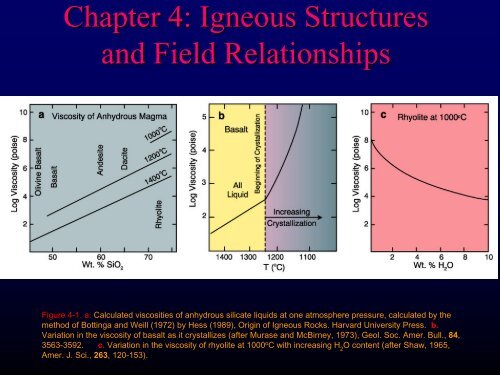
Figure 4-1. 4<br />
a. Calculated viscosities of anhydrous silicate liquids at one atmosphere pressure, calculated by the<br />
method of Bottinga <strong>and</strong> Weill (1972) by Hess (1989), Origin of <strong>Igneous</strong> Rocks. Harvard University Press. b.<br />
Variation in the viscosity of basalt as it crystallizes (after Murase <strong>and</strong> McBirney, 1973), Geol. Soc. Amer. Bull., 84,<br />
3563-3592.<br />
3592. c. Variation in the viscosity of rhyolite at 1000 o C with increasing H 2<br />
O content (after Shaw, 1965,<br />
Amer. J. Sci.,<br />
263, , 120-153<br />
153).
<strong>Structures</strong> <strong>and</strong> <strong>Field</strong> <strong>Relationships</strong><br />
Figure 4-2. 4 Volcanic l<strong>and</strong>forms associated with a central vent (all at same scale). s
<strong>Structures</strong> <strong>and</strong> <strong>Field</strong> <strong>Relationships</strong><br />
Figure 4-3. 4 a. Illustrative cross section of a stratovolcano.<br />
After Macdonald (1972), Volcanoes. . Prentice-Hall, Inc.,<br />
Englewood Cliffs, N. J., 1-150. 1 150. b. Deeply glaciated north<br />
wall of Mt. Rainier, WA, a stratovolcano, showing layers of<br />
pyroclastics <strong>and</strong> lava flows. © John Winter <strong>and</strong> Prentice<br />
Hall.
<strong>Structures</strong> <strong>and</strong> <strong>Field</strong> <strong>Relationships</strong><br />
Projected former height of Brokeoff Volcano<br />
Lassen Peak<br />
Brokeoff Mountain<br />
Eagle Peak<br />
Figure 4-4. 4 Schematic cross section of the Lassen Peak area. After Williams (1932),<br />
Univ. of Cal. Publ. . Geol. Sci. . Bull., , 21.
<strong>Structures</strong> <strong>and</strong> <strong>Field</strong> <strong>Relationships</strong><br />
Figure 4-5. 4 Cross sectional structure <strong>and</strong> morphology of<br />
small explosive volcanic l<strong>and</strong>forms with approximate<br />
scales. After Wohletz <strong>and</strong> Sheridan (1983), Amer. J.<br />
Sci, 283, , 385-413.
Figure 4-6. 4 a. Maar: : Hole-in<br />
in-the-Ground, Oregon (upper courtesy of<br />
USGS, lower my own). b. Tuff ring: : Diamond Head, Oahu, Hawaii<br />
(courtesy of Michael Garcia). c. Scoria cone, Surtsey, , Icel<strong>and</strong>, 1996<br />
(© courtesy Bob <strong>and</strong> Barbara Decker).<br />
a<br />
b<br />
c
<strong>Structures</strong> <strong>and</strong> <strong>Field</strong> <strong>Relationships</strong><br />
Figure 4-7. 4 Schematic cross section through a lava dome.
<strong>Structures</strong> <strong>and</strong> <strong>Field</strong> <strong>Relationships</strong><br />
Figure 4-8. 4<br />
Pressure ridges on the surface of Big Obsidian Flow, Newberry Volcano, V<br />
OR. Flow direction is toward the left.<br />
© John Winter <strong>and</strong> Prentice Hall.
<strong>Structures</strong> <strong>and</strong> <strong>Field</strong> <strong>Relationships</strong><br />
Figure 4-9. Development of the Crater Lake caldera. After<br />
Bacon (1988). Crater Lake National Park <strong>and</strong> Vicinity,<br />
Oregon. 1:62,500-scale topographic map. U. S. Geol. Surv.<br />
Natl. Park Series.
<strong>Structures</strong> <strong>and</strong> <strong>Field</strong> <strong>Relationships</strong><br />
Figure 4-104<br />
10. Location of the exposed feeder<br />
dikes (heavy lines) <strong>and</strong> vents (V's) of the<br />
southeastern portion of the Columbia River<br />
Basalts. Unshaded area covered by CRB. After<br />
Tolan et al. . (1989), © Geol. Soc. Amer. Special<br />
Paper, 239. . pp. 1-20. 1
<strong>Structures</strong> <strong>and</strong> <strong>Field</strong> <strong>Relationships</strong><br />
Figure 4-114<br />
11. Aerial extent of the N2 Gr<strong>and</strong>e Ronde flow unit (approximately 212<br />
1 flows). After Tolan et al. (1989). ©<br />
Geol. Soc. Amer. Special Paper, 239. . pp. 1-20. 1
a<br />
Figure 4-124<br />
12. a. Ropy surface of a pahoehoe flow,<br />
1996 flows, Kalapana area, Hawaii. © John<br />
Winter <strong>and</strong> Prentice Hall.<br />
Figure 4-124<br />
12. b. Pahoehoe (left) <strong>and</strong> aa (right) meet in<br />
the 1974 flows from Mauna Ulu, , Hawaii. © John Winter<br />
<strong>and</strong> Prentice Hall.<br />
b
c<br />
Figure 4-124<br />
12. c-e.<br />
Illustration of the development of an<br />
inflated flow. In d, , a thin flow spreads around a rock wall.<br />
In (e),(<br />
the flow is inflated by the addition of more lava<br />
beneath the earlier crust. A old stone wall anchors the<br />
crust, keeping it from lifting. The wall can be seen in the<br />
low area in part (c). © John Winter <strong>and</strong> Prentice Hall.
Figure 4-134<br />
13. a. Schematic drawing of columnar joints in a basalt flow, showing the four common subdivisions of a typical flow. The<br />
column widths in (a) are exaggerated about 4x. After Long <strong>and</strong> Wood od (1986) © Geol. Soc. Amer. Bull., 97, , 1144-1155.<br />
1155.<br />
b. Colonnade-entablature<br />
entablature-colonnade in a basalt flow, Crooked River Gorge, OR. © John Winter <strong>and</strong> Prentice Hall.
<strong>Structures</strong> <strong>and</strong> <strong>Field</strong> <strong>Relationships</strong><br />
Figure 4-14. 4<br />
Sub-aqueous pillow basalts, Olympic<br />
Peninsular, WA © John Winter <strong>and</strong> Prentice Hall.
Figure 4-154<br />
15. Ash cloud <strong>and</strong> deposits of the 1980<br />
eruption of Mt. St. Helens.<br />
a. Photo of Mt. St. Helens vertical ash column,<br />
May 18, 1980 (courtesy USGS). b. Vertical<br />
section of the ash cloud showing temporal<br />
development during first 13 minutes. c. Map<br />
view of the ash deposit. Thickness is in cm. After<br />
Sarna-Wojcicki<br />
et al. ( 1981) in The 1980<br />
Eruptions of Mount St. Helens, Washington.<br />
USGS Prof. Pap., 1250, , 557-600.
Figure 4-164<br />
16. Approximate aerial extent <strong>and</strong> thickness of Mt. Mazama (Crater Lake) L<br />
ash fall, erupted 6950 years ago. After Young<br />
(1990), Unpubl. . Ph. D. thesis, University of Lancaster. UK.
Figure 4-174<br />
17. Maximum aerial extent of the Bishop ash fall deposit erupted at Long<br />
Valley 700,000 years ago. After Miller et al. . (1982) USGS Open-File Report 82-583.
Figure 4-184<br />
18. Types of pyroclastic flow deposits.<br />
After MacDonald (1972), Volcanoes. . Prentice-Hall,<br />
Inc., Fisher <strong>and</strong> Schminke (1984), Pyroclastic<br />
Rocks. SpringerS<br />
pringer-Verlag. . Berlin.<br />
a. collapse of a vertical explosive or plinian column<br />
that falls back to earth, <strong>and</strong> continues to travel along<br />
the ground surface.<br />
b. Lateral blast, such as occurred at Mt. St. Helens<br />
in 1980.<br />
c. “Boiling-over” of a highly gas-charged magma<br />
from a vent.<br />
d. Gravitational collapse of a hot dome (Fig. 4-18d). 4
<strong>Structures</strong> <strong>and</strong> <strong>Field</strong><br />
<strong>Relationships</strong><br />
Figure 4-194<br />
19. Section through a typical ignimbrite,<br />
showing basal surge deposit, middle flow, <strong>and</strong><br />
upper ash fall cover. Tan blocks represent<br />
pumice, <strong>and</strong> purple represents denser lithic<br />
fragments. After Sparks et al. (1973) Geology, 1,<br />
115-118. 118. Geol. Soc. America
<strong>Structures</strong> <strong>and</strong> <strong>Field</strong> <strong>Relationships</strong><br />
Figure 4-204<br />
20. Schematic block diagram of some intrusive bodies.
Figure 4-21. Kangâmiut dike swarm in the Søndre<br />
Strømfjord region of SE Greenl<strong>and</strong>. From Escher et al.<br />
(1976), Geology of Greenl<strong>and</strong>, © The Geological<br />
Survey of Denmark <strong>and</strong> Greenl<strong>and</strong>. 77-95.
Figure 4-22. a. Radial dike swarm around Spanish Peaks, Colorado. After Knopf (1936), Geol. Soc. Amer.<br />
Bull., 47, 1727-1784. b. Eroded remnant of a volcanic neck with radial dikes. Ship Rock, New Mexico. From<br />
John Shelton © (1966) Geology Illustrated. W. H. Freeman. San Francisco.
Figure 4-23. The<br />
formation of ring dikes<br />
<strong>and</strong> cone sheets.<br />
a. Cross section of a<br />
rising pluton causing<br />
fracture <strong>and</strong> stoping of<br />
roof blocks.<br />
b. Cylindrical blocks<br />
drop into less dense<br />
magma below,<br />
resulting in ring dikes.<br />
c. Hypothetical map<br />
view of a ring dike with<br />
N-S striking country<br />
rock strata as might<br />
result from erosion to a<br />
level approximating X-<br />
Y in (b).<br />
d. Upward pressure of<br />
a pluton lifts the roof as<br />
conical blocks in this<br />
cross section. Magma<br />
follows the fractures,<br />
producing cone sheets.<br />
Original horizontal<br />
bedding plane shows<br />
offsets in the conical<br />
blocks. (a), (b), <strong>and</strong> (d)<br />
after Billings (1972),<br />
Structural Geology.<br />
Prentice-Hall, Inc. (c)<br />
after Compton (1985),<br />
Geology in the <strong>Field</strong>. ©<br />
Wiley. New York.
Figure 4-24. a. Map of ring dikes,<br />
Isl<strong>and</strong> of Mull, Scotl<strong>and</strong>. After Bailey<br />
et al. (1924), Tertiary <strong>and</strong> posttertiary<br />
geology of Mull, Loch Aline<br />
<strong>and</strong> Oban. Geol. Surv. Scot. Mull<br />
Memoir. Copyright British Geological<br />
Survey.
Figure 4-24. b. Cone sheets in the same area of Mull, after Ritchey (1961), British Regional Geology. Scotl<strong>and</strong>, the Tertiary Volcanic<br />
Districts. Note that the yellow felsite ring dike in part (a) is shown as the red ring in the NW of part (b). British Geological Survey.
<strong>Structures</strong> <strong>and</strong> <strong>Field</strong> <strong>Relationships</strong><br />
Figure 4-26. Shapes of two concordant plutons.<br />
a. Laccolith with flat floor <strong>and</strong> arched roof.<br />
b. Lopolith intruded into a structural basin. The scale is not the same for these two plutons, a lopolith is generally much<br />
larger. © John Winter <strong>and</strong> Prentice Hall.
<strong>Structures</strong> <strong>and</strong> <strong>Field</strong> <strong>Relationships</strong><br />
Figure 4-304<br />
30. Block diagram several kilometers across, illustrating some relationships with the country rock near the top<br />
of a barely exposed pluton in the epizone. The original upper contact above the surface is approximated by the dashed<br />
line on the front plane. From Lahee (1961), <strong>Field</strong> Geology. © McGraw Hill. New York.
<strong>Structures</strong> <strong>and</strong> <strong>Field</strong> <strong>Relationships</strong><br />
Figure 4-314<br />
31. a. General characteristics of plutons in the epizone, mesozone, <strong>and</strong><br />
catazone. From Buddington (1959), Geol. Soc. Amer. Bull., 70, , 671-747.<br />
747.
<strong>Structures</strong> <strong>and</strong> <strong>Field</strong> <strong>Relationships</strong><br />
Figure 4-334<br />
33. Block diagram of subsurface salt diapirs in Northern Germany. After A<br />
Trusheim (1960), Bull. Amer. Assoc. Petrol. Geol., 44, , 1519-1540<br />
1540 © AAPG.
Figure 4-344<br />
34. Diagrammatic illustration of proposed pluton emplacement mechanisms.<br />
1- doming of roof; 2- wall rock assimilation, partial melting, zone melting; 3- stoping;<br />
4- ductile wall rock deformation <strong>and</strong> wall rock return flow; 5- lateral wall rock displacement by faulting or folding;<br />
6- (<strong>and</strong> 1)- emplacement into extensional environment. After Paterson et al. . (1991), Contact Metamorphism. Rev. in<br />
Mineralogy, 26, , pp. 105-206.<br />
© Min. Soc. Amer.