
You also want an ePaper? Increase the reach of your titles
YUMPU automatically turns print PDFs into web optimized ePapers that Google loves.
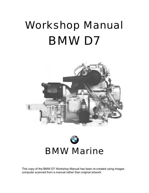
<strong>Workshop</strong> <strong>Manual</strong><br />
<strong>BMW</strong> <strong>D7</strong><br />
<strong>BMW</strong> Marine<br />
This copy of the <strong>BMW</strong> <strong>D7</strong> <strong>Workshop</strong> <strong>Manual</strong> has been re-created using images<br />
computer scanned from a manual rather than original artwork.
<strong>BMW</strong> <strong>D7</strong> Marine Engine<br />
A four-stroke diesel engine with direct injection and open-circuit cooling system. The<br />
Neoprene impeller of the coolant pump is driven directly from the crankshaft. Electric<br />
starter and flywheel alternator are standard equipment. The injection system is fitted with<br />
automatic bleeding.<br />
Notes on Use<br />
This workshop manual describes complete procedures for dismantling, overhaul and<br />
assembly of the <strong>BMW</strong> <strong>D7</strong> marine engine.<br />
If only part of the procedure is to be carried out (e.g. small repairs or replacement of<br />
gaskets, oilseals) the remainder can be ignored.<br />
The relevant technical data is provided with each section. General specifications are found<br />
on page iii.<br />
Assembly is generally a reversal of removal procedure. Special attention, however, should<br />
be paid to "notes on assembly".<br />
Checking and adjustment procedures, where applicable, are to be found at the end of the<br />
relevant section.<br />
i
Contents<br />
Page<br />
Page<br />
Introduction i Fuel System 27<br />
Remove, adjust:<br />
Summary 1 - Injection valve 27<br />
- Injection pump 29<br />
Removing cylinder head 3 - Engine speed 31<br />
- Preparations 3 Check:<br />
- Valve mechanism 4 - Injection pump 32<br />
- Valves 5 - Injection valve 32<br />
- Cylinder head 7 - Fuel pump 32<br />
- Cylinder 7<br />
Air filter 33<br />
Removing gearbox 8<br />
- Starter 8 Electrical system 34<br />
- Reversing gear 8 - Wiring diagram 34<br />
- Bearing cover 9 - Generator 35<br />
- Hand crank mechanism 10 - Starter motor 39<br />
- Connecting rod 11<br />
- Piston 13 Water Pump 40<br />
- Fuel pump 14<br />
- Timing gear cover 14<br />
- Fuel regulator 15<br />
- Crankshaft 16<br />
- Valve lifters 19<br />
- Camshaft 20<br />
Assemble crankshaft 20<br />
- Camshaft 20<br />
- Crankshaft 20<br />
- Fuel regulator 21<br />
- Timing gear cover 21<br />
- Fuel pump 21<br />
- Piston 21<br />
- Connecting rod 21<br />
- Hand crank mechanism 21<br />
- Bearing cover 22<br />
- Reversing gear 22<br />
- Starter<br />
Assemble cylinder head 22<br />
- Cylinder 22<br />
- Cylinder head 23<br />
- Valves 23<br />
- Valve mechanism 23<br />
- Hoses & pipes 23<br />
Adjust: 24<br />
- Valve clearance - valve timing 24<br />
- Decompression lever 25<br />
- Automatic decompression 26<br />
General<br />
ii
Technical data<br />
Capacity<br />
280cc / 17.1 cu.in.<br />
Bore x stroke<br />
73 mm x 67 mm / 2.87 in x 2.64 in<br />
Max. power<br />
4.5 kw / 6 bhp @ 3600 rpm<br />
Compression ratio 22 : 1<br />
Dry weight with gearbox<br />
68 kg / 150 lbs<br />
Gearbox reduction forward 2.7:1, reverse 1.9:1<br />
Max. installation angle<br />
15 o<br />
Specifications<br />
Fuel Diesel oil, DIN 51601/USA #2<br />
Lubricating oil, engine<br />
HD-API CC/CD<br />
gearbox Hurth ATF Dexron - ZF SAE 20 W 20<br />
Oil capacity, engine<br />
2 litres / 3.5 pints UK / 4.4 pints US<br />
gearbox<br />
0.4 litres / 0.7 pints UK / 0.85 pints US<br />
Fuel filter <strong>BMW</strong> 13 32 1 328 270<br />
Air filter <strong>BMW</strong> 13 71 1 329 269<br />
Injector<br />
Bosch<br />
Injection pressure<br />
135 + 8 bar<br />
Injection pump<br />
Bosch PFR 1 K 70 A 343/II<br />
Starter motor<br />
Bosch 0.8 kw<br />
Generator<br />
14V 350W 25A<br />
Battery<br />
12V 60 Ah<br />
Gearbox Hurth HBW5 - ZF Bw 3<br />
Adjustment data<br />
Injection ends<br />
Valve clearances, cold<br />
11.5 o - 12.5 o BTDC<br />
0.15 mm / .006 in.<br />
Torque settings<br />
Nm kpm Remarks<br />
Cylinder head nuts M 8 40 4.0 Use permanently elastic<br />
sealing compound (e.g.<br />
Atmosit) on the stud screws<br />
in the oil space!<br />
Connecting rod screws 40 4.0 Oil threads and screw head<br />
insert lightly<br />
Counter weight screws 22 2.2 Oil threads and screw head<br />
insert lightly<br />
M 6 hex nut for the mounting of the injector 10 1.0<br />
Flywheel bolts M 10 70 7.0<br />
Injection pump delivery valve 40 4.0<br />
M 6 hex head screw for fastening bearing 10 1.0<br />
cover retaining yoke on the flywheel side<br />
Nozzle nut 85 8 - 9<br />
iii
List of Special Tools <strong>D7</strong><br />
<strong>BMW</strong> Part No.<br />
Description<br />
74 64 1 333 525 To refit ball hub<br />
74 64 1 333 526 To refit crankshaft gear<br />
74 64 1 333 513 Crankshaft installation tool<br />
74 64 1 333 514 Puller for valve lifter shaft<br />
74 64 1 333 515 Tool for crankshaft removal<br />
74 64 1 333 516 Tool for camshaft needle bearing installation<br />
74 64 1 333 517 Wrench for injection adjuster<br />
74 64 1 333 527 Crankshaft gear puller<br />
74 64 1 333 535 Tool for adjustment of injection pump<br />
74 64 1 333 528 Tool for injection adjuster<br />
74 64 1 333 536 Multi purpose extractor<br />
74 64 1 333 529 Auxiliary wrench for cable connector<br />
74 64 1 333 530 Sleeve 27 - 36 mm internal extractor<br />
74 64 1 333 531 Counter support-internal extractor<br />
74 64 1 333 537 Allen socket with center pin 8 mm<br />
74 64 1 333 538 Allen socket with center pin 10 mm<br />
74 64 1 333 539 Clamping holder to grind valve-valveseat<br />
74 64 1 333 540 Allen wrench 6 mm elongated<br />
74 64 1 333 518 Auxillary bush-oil seal<br />
74 64 1 333 519 Punch - needle bearing camshaft<br />
74 64 1 333 520 Socket 13 mm (long size)<br />
74 64 1 333 541 Allen socket 6 mm<br />
74 64 1 333 521 Retaining bracket for cylinder<br />
74 64 1 333 542 Press-in mandrel-valve guide 7 mm Ø<br />
74 64 1 333 532 Hand reamer 7 mm Ø H 7 for valve guide<br />
74 64 1 333 543 Flare nut wrench 17/19 mm<br />
74 64 1 333 522 Special tool for governor spring<br />
74 64 1 333 523 Box wrench 10mm<br />
74 64 1 333 524 Piston ring clamp<br />
74 64 1 333 544 Measuring device for bumping clearance<br />
74 64 1 333 545 Testing device for injection equipment<br />
74 64 1 333 546 Dial gauge 1/100 mm<br />
74 64 1 333 547 Torque wrench 1 - 140 NM<br />
74 64 1 333 534 Guiding pin 7 mm Ø (valve reseating tool)<br />
74 64 1 333 548 Handle for valve reseating tool<br />
74 64 1 333 549 Piston ring pliers<br />
74 64 1 333 550 Allen socket 8 mm<br />
74 64 1 333 551 Valve reseating tool 42.5 mm Ø<br />
74 64 1 333 552 Gudgeon pin extractor<br />
iv
Summary<br />
<strong>BMW</strong> Marine Diesel Engine <strong>D7</strong><br />
Description:<br />
Water cooled single cylinder four stroke producing 4.5 kW (DIN) (6 Hp)<br />
1. Cylinder head cover<br />
2. Decompression lever<br />
3. Throttle cable mount<br />
4. Hand crank attachment<br />
5. Cover<br />
6. Sea water pump<br />
7. Fitting<br />
8. Hose clips<br />
9. Sea water hose<br />
10. Engine mounts<br />
11. Cylinder head<br />
12. Metering device<br />
13. Fuel return hose<br />
14. Injector<br />
15. Air filter<br />
16. Fuel injection pipe<br />
17. Injection pump<br />
18. Throttle<br />
19. Dipstick<br />
20. Oil filler screw<br />
General<br />
1
Summary<br />
21. Exhaust<br />
22. Starter<br />
23. Retainer yoke<br />
24. Gear box<br />
25. Crankcase<br />
26. Fuel pump<br />
27. Fitting<br />
28. Sea water pipe<br />
CAUTION<br />
To avoid damage to engine parts, always<br />
use special tools as shown in the illustrations.<br />
The tools to be used fit only in the position shown.<br />
General<br />
2
Cylinder Head<br />
Removing cylinder head and cylinder<br />
- Remove air filter (1)<br />
- Loosen sea water pipe from exhaust manifold<br />
and water pump and remove (2) + (3)<br />
CAUTION<br />
Cover all openings in the fuel system<br />
- Disconnect fuel return hose from<br />
injector and remove (4)<br />
- Disconnect fuel injection pipe from<br />
injector and injection pump and<br />
remove (5)<br />
- Remove clip of crankcase vent<br />
hose (6), unscrew both nuts of the<br />
rocker cover and remove the<br />
rocker cover with gasket (7)<br />
Detach<br />
Disassemble<br />
Remove<br />
Air filter, seawater hose, fuel overflow hose, cylinder head vent hose clip,<br />
cylinder head cover with gasket, rocker shaft with rockers, pushrods<br />
3
Cylinder Head<br />
- Remove rocker shaft with bushing and retainer yoke<br />
and remove rockers (8) and (9)<br />
- Pull out both pushrods<br />
Dimension<br />
Cylinder Head Repair Data<br />
<strong>D7</strong> nominal<br />
values<br />
Max. allowable<br />
wear (mm)<br />
Remarks<br />
Rocker arms<br />
shaft dia.<br />
mm<br />
18 -0.027<br />
0.05<br />
Rocker arm<br />
internal dia.<br />
mm<br />
18<br />
+0.024<br />
+0.006<br />
0.05<br />
After press fitting<br />
Rockaer arm<br />
radius<br />
mm<br />
8<br />
No flats<br />
Valve seat angle<br />
o<br />
45<br />
Detach<br />
Disassemble<br />
Remove<br />
Rocker shaft with rockers, pushrods<br />
4
Cylinder Head, Timing Gear<br />
- Remove decompression lever from the<br />
underside of the cylinder head (10)<br />
- Unscrew the M10 nut and unscrew stud bolt.<br />
- Remove the spring<br />
- Remove retaining pin with pointed pliers<br />
- Unscrew inner clamping sleeve on gear<br />
segment and remove shaft and gear segment.<br />
- Remove valves & valve springs (11)<br />
- Press down the spring retainers<br />
WARNING<br />
Danger of injury due to spring retainers and<br />
valve keys popping out.<br />
- Loosen both key halves while applying pressure<br />
from below and remove with pointed pliers.<br />
- Remove cap and washer from under the valve<br />
spring<br />
- Remove valve<br />
- Press out the valve guides from below<br />
NOTE<br />
When pressing in the new valve guides,<br />
when parts are cold note minimum force<br />
of 1000 N (approx 100 kp)<br />
- Ream the valve guides<br />
- Rework leaky valve seats with a 45 o valve seat<br />
cutter. Mill only enough to remove spots from<br />
valve seats.<br />
- Reseat valves using auxiliary tool<br />
- No 74 64 1 333 539<br />
Detach<br />
Remove<br />
Rework<br />
Decompression lever handle, clamping sleeve on handle, spring shaft,<br />
valve poppets, spring plate with valve spring, cone halves, valve guides<br />
5
Cylinder Head<br />
The valves should sit back as measured from the seating surface of the cylinder head, according to the<br />
following table:<br />
Cylinder Head<br />
Dimension<br />
Repair Data Valves<br />
<strong>D7</strong> nominal Max. allowable<br />
values wear (mm)<br />
Remarks<br />
Valve clearance<br />
cold<br />
mm<br />
0.15<br />
Intake valve stem<br />
dia<br />
mm<br />
7<br />
-0.04<br />
-0.05<br />
0.05<br />
Exhaust valve<br />
stem dia<br />
mm<br />
7<br />
-0.05<br />
-0.04<br />
0.05<br />
Intake valve<br />
disc dia<br />
mm<br />
30.5<br />
Exhaust valve disc<br />
dia<br />
Valve sit back max<br />
Valve sit back min<br />
Valve guide bore<br />
Outer diameter<br />
Valve guide bore in<br />
cylinder head<br />
Valve guide press<br />
in force<br />
mm<br />
mm<br />
mm<br />
mm<br />
mm<br />
mm<br />
kp<br />
30.5<br />
0.70<br />
0.45<br />
7<br />
10<br />
10<br />
100<br />
+0.09<br />
0<br />
+0.023<br />
+0.029<br />
+0.0011<br />
0.05<br />
CAUTION!<br />
Valve sit back may not be less<br />
than 0.45 mm as otherwise the<br />
danger exists that the valve disc<br />
hits the piston.<br />
The sealing surface of the<br />
cylinder head can be reworked to<br />
a maximum of 0.5 mm if the sit<br />
back of<br />
0.7 mm is exceeded due to valve<br />
seat milling.<br />
With the cylinder head cold.<br />
Table: Valve sit back<br />
6
Cylinder Head / Cylinder<br />
Remove cylinder head and pull off cylinder (12)<br />
The cylinder head is unusable in the following<br />
cases:<br />
- Sealing surface fouled or damaged i.e. uneven<br />
- Clean the sealing surface and re-grind,<br />
observing the tolerances<br />
- Valve seats worn out or no longer suitable for<br />
re-facing.<br />
- Cracks in the valve seats in the cylinder head<br />
NOTE<br />
Measure cylinder bore with a cylinder indicator<br />
In the following cases, the cylinder is unusable:<br />
- Seize marks are found in the bore<br />
- Scratches are present<br />
- Wear exceeds 0.15 mm<br />
Cylinder<br />
Dimension<br />
Repair Data Cylinder<br />
<strong>D7</strong> nominal Max. allowable<br />
values wear (mm)<br />
Remarks<br />
Bore dia<br />
mm<br />
73 + 0.01<br />
0.15<br />
Roughness Ra<br />
µ<br />
1.0 – 1.2<br />
Oversizes<br />
mm<br />
+ 1<br />
Remove Unusability of cylinder head/cylinder<br />
Detach Cylinder head, cylinder<br />
7
Bearing cover<br />
Remove starter (13) - Remove attaching clamp of the cable to the<br />
stator and remove starter<br />
- Remove the four cyclinder screws M 10 and<br />
remove the flywheel (15) and (16)<br />
Remove gearbox (14) complete with flywheel<br />
cover.<br />
Remove bearing cover<br />
Detach<br />
8
Bearing cover<br />
NOTE<br />
- After loosening the four M6 hex screws, remove<br />
the bearing cover with locking plate and the<br />
sealing ring located on the inner face (17)<br />
Bearing cover can be replaced when the engine is<br />
cold<br />
Remove bearing cover<br />
Detach<br />
9
Cover to timing gear cover / timing gear cover / hand cranking device<br />
- Remove screws from cover of timing<br />
gear cover and take off the cover (18)<br />
- Remove hand crank mechanism (19)<br />
with extractor tool No 666 332 00<br />
Detach Cover of timing gear cover, hand crank device, dipstick, cover on engine bottom,<br />
Remove connecting rod<br />
10
Dipstick / cover on engine bottom / connecting rod<br />
- Turn the engine on to the flywheel side (23) and<br />
remove dipstick (24)<br />
- Remove cover and O-ring from crankcase on<br />
the engine bottom (25).<br />
- Unscrew the two connecting rod screws (26).<br />
- Take out connecting rod cap with oil pick-up<br />
(27) from below and piston and connecting rod<br />
(28) from top.<br />
Detach<br />
Remove<br />
Dipstick / cover on engine bottom / connecting rod<br />
11
Table: Repair data for connecting rod and connecting rod bearing<br />
Repair Data for con-rod bearing and con-rod<br />
Con-rod bearing<br />
Dimension<br />
<strong>D7</strong> nominal<br />
values<br />
Max. allowable<br />
wear (mm)<br />
Remarks<br />
Outer dia<br />
mm<br />
46<br />
Minimum bearing play =<br />
0.040-0.076mm when new<br />
Inner dia<br />
mm<br />
42<br />
+0.016<br />
-0.026<br />
see table on page<br />
17<br />
max wear to 0.15mm<br />
Width<br />
mm<br />
26.5<br />
Undersize<br />
mm<br />
41.5<br />
see table on page<br />
17<br />
Con-rod bearing<br />
wall thickness<br />
normal(W)<br />
Con-rod bearing<br />
wall thickness<br />
oversize(WU)<br />
mm<br />
mm<br />
1.998<br />
2.248<br />
+0.02<br />
+0.02<br />
Total play after<br />
wear:<br />
max 0.15mm<br />
Con-rod<br />
Gudgeon pin<br />
bushing bore dia<br />
mm<br />
28<br />
+0.013<br />
0<br />
Con-rod bearing<br />
bore dia<br />
mm<br />
46<br />
+0.010<br />
-0.006<br />
Gudgeon pin<br />
bushing:<br />
outer dia<br />
mm<br />
28<br />
+0.048<br />
+0.035<br />
inner dia – loose<br />
mm<br />
25<br />
+0.082<br />
+0.068<br />
0.20<br />
- installed<br />
mm<br />
25<br />
+0.020<br />
+0.007<br />
Thread con-rod<br />
bolts<br />
M8<br />
12
Piston<br />
Note<br />
Heat piston to remove piston pin<br />
- Remove the gudgeon pin snap rings and press<br />
out the gudgeon pin by hand while the parts are<br />
still warm (29).<br />
In the following cases, the piston is unusable:<br />
- ring land between the rings broken<br />
- piston scuffed<br />
- ring groove worn out<br />
- and cracked<br />
Piston rings are unusable when the gap is too<br />
big<br />
Repair Data<br />
Piston<br />
Dimension<br />
<strong>D7</strong> nominal<br />
values<br />
Max. allowable<br />
wear (mm)<br />
Remarks<br />
Piston dia<br />
mm<br />
72.96<br />
Oversize<br />
mm<br />
+1.00<br />
Overall length<br />
mm<br />
82mm<br />
Piston ring gap<br />
(new condition)<br />
mm<br />
0.25 – 0.4 Up to 2.00<br />
Unscrew<br />
Detach<br />
Piston<br />
13
Fuel pump / timing gear cover<br />
- Remove fuel pump (29a)<br />
- Remove pump plunger (29b)<br />
- Unscrew the three M16 hex nuts and<br />
remove timing gear cover (29c)<br />
Detach<br />
Remove<br />
Fuel pump, pump plunger, timing gear cover<br />
14
Fuel regulator, gear on crankshaft<br />
- Bring engine into the horizontal position, as<br />
shown in Fig (29d)<br />
- Remove gear from crankshaft using extractor<br />
tool (29k)<br />
- Loosen M6 hex nut (29f) on the regulator lever<br />
and pull out locking pin with pointed pliers<br />
- Unscrew both M10 hex nuts (29e) from<br />
regulator shaft.<br />
- Remove regulator shaft together with round<br />
nut, spring washer, sealing ring and friction<br />
disc.<br />
- Unscrew M8 hex nut. Withdraw eccentric bolt<br />
with cap plate and sealing ring<br />
- Loosen M20 hex nut. Remove start filling (29h)<br />
with sealing ring.<br />
- Pull out clamping sleeve, using pointed pliers.<br />
- Withdraw regulator lever with regulator spring<br />
(29i)<br />
- Turn engine on flywheel side.<br />
Repair Data for Regulator Spring Washers<br />
Maximum rpm No of balls Regulator Spring <strong>BMW</strong> Part No Wire Dia<br />
3600/160 4 13 41 1 329 652 2.6<br />
Remove Regulator lever with regulator spring<br />
15
Ball sleeve / Crankshaft<br />
- Remove ball sleeve with sliding disc taking care<br />
that no balls fall out (30)<br />
Ball hub and spacer washer (31) remain on<br />
crankshaft. Detach these parts only when<br />
removing the crankshaft.<br />
- Turn the engine block into the horizontal position.<br />
Removing the crankshaft<br />
NOTE<br />
It is essential that all plastic parts such as oil filler<br />
cover and cold start cover are removed<br />
- Heat the crankcase on a heating plate to between<br />
80 and 100 o C (32)<br />
- Press out the crankshaft with extractor tool (33)<br />
74 64 1 333 515<br />
- Press off the roller bearing on timing side (33a)<br />
- Press off straight roller bearing together with<br />
spacer washer and drive dog hub (34)<br />
Remove Ball sleeve, crankshaft<br />
16
Crankshaft<br />
The outer race of the straight roller bearing on<br />
the timing gear side remains in the crankcase<br />
and can be removed with the aid of a press<br />
In order to remove the bearing rings which have<br />
been shrunk on to the crankshaft (35) heat the<br />
crankshaft on a heating plate or with a sufficiently<br />
large gas burner rapidly to about 70 to 80 o C<br />
After removal of the M8 cylinder head screws,<br />
remove the counterweights (36).<br />
Set the crankshaft on a solid support and loosen<br />
bearing race by a blow to the crankshaft.<br />
Repair Data for Crankshaft Crank Pins<br />
Crank pins must not become convex upon regrinding. A concave shape of from 0.01 to 0.02 mm in diameter<br />
in the mid portion of length is allowable.<br />
-0.060<br />
+0.074<br />
Crank pin nominal diameter (D) 42 mm<br />
-0.060<br />
-0.074<br />
Crank pin diameter undersize (DU) 41.5 mm<br />
Total play when worn out max<br />
0.15mm<br />
Remove Crankshaft<br />
17
Table: Repair data for crankshaft<br />
Repair Data for Crankshaft<br />
Crankshaft<br />
Dimension<br />
<strong>D7</strong> nominal<br />
values<br />
Max. allowable<br />
wear (mm)<br />
Remarks<br />
Crank pin dia<br />
mm<br />
42.0<br />
-0.060<br />
-0.070<br />
Total play 0.15 max<br />
Max allowable crank pin<br />
out-of-round 0.05mm<br />
End float<br />
µ<br />
0.3<br />
Crankshaft crank<br />
pin width<br />
mm<br />
33.0<br />
+0.068<br />
0<br />
Radii on crank pin<br />
mm<br />
3.0<br />
Hardness of crank<br />
pin<br />
RC<br />
50-55<br />
Depth of hardening<br />
of crank pin<br />
mm<br />
1.1-1.5<br />
Diameter of ball<br />
hub (regulator)<br />
mm<br />
29.0<br />
+0.021<br />
0<br />
Diameter of ball<br />
sleeve<br />
mm<br />
28.0<br />
-0.020<br />
-0.041<br />
Diameter of gear<br />
on crankshaft<br />
mm<br />
22.0<br />
+0.048<br />
+0.035<br />
Regrinding of<br />
crankpin<br />
mm<br />
0.5<br />
Grinding finish see<br />
page 17<br />
Hardness at least<br />
48 RC<br />
Axial play<br />
mm<br />
0.3-0.4<br />
18
Valve lifters and camshaft<br />
- Remove the plastic plug from the side of<br />
the engine block (37)<br />
- Unscrew the M8 set screw (38) with a 4<br />
mm Allen key and remove together with<br />
plug<br />
CAUTION<br />
When removing the camshaft, lift<br />
off both rockers from the camshaft<br />
to prevent damage by the cam<br />
lobes<br />
- Pull out valve rocker shaft with the aid of<br />
extractor tool No 74 64 1 333 514 (39)<br />
- Remove valve rockers together with<br />
washer (39b, 39c)<br />
- Replace valve rockers if worn.<br />
- Withdraw camshaft<br />
- Press roller bearing off the camshaft<br />
- Rotate crankshaft so that the needle<br />
bearing becomes accessible.<br />
- A damaged camshaft needle bearing can<br />
be removed from the crankcase with drift<br />
punch No 74 64 1 333 519.<br />
Remove<br />
Valve lifter shaft, valve lifters, camshaft, roller bearing<br />
19
Camshaft<br />
Crankshaft<br />
Reassembly of the engine parts is carried out in the reverse order.<br />
Installing the crankshaft<br />
NOTE<br />
The tooth gear on the camshaft is marked with the<br />
letter “L”. This indicates the direction of rotation of<br />
the engine as viewed from the front.<br />
- Attach the counterweights, tightening the bolts<br />
to a torque of 2.2 kg/m (16 lb/ft)<br />
- Heat the inner race of the roller bearing to<br />
between 70 and 80 o C and mount on the<br />
crankshaft.<br />
- Place the retainer ring on the outer bearing<br />
race.<br />
- Push inner straight roller bearing onto the<br />
crankshaft together with spacer washer and<br />
drive dog hub.<br />
- Heat the crankcase to between 100 and 150 o C<br />
on a heating plate.<br />
- Push the outer race of the bearing on the<br />
flywheel side onto the crankshaft and screw it<br />
on using special tool No 74 64 1 333 513<br />
- Drive in the rear camshaft bearing using the<br />
assembly punch No 74 64 1 333 516.<br />
- Install the camshaft.<br />
- Screw in the set screw and replace the plastic<br />
plug.<br />
- Insert the valve lifter shaft and tighten, so that<br />
the valve lifters show a minimum of axial play<br />
but are still free to move on the valve lifter shaft.<br />
NOTE<br />
Take care that the thrust washer is<br />
placed between the valve lifters and the<br />
crankcase to prevent the valve lifters<br />
from wearing into the aluminium case.<br />
CAUTION<br />
The crankshaft bearing is asymmetrical.<br />
The correct position is that shown in the<br />
illustration (41). The large rounding must<br />
be placed towards the outside, to ensure<br />
sufficient lubrication.<br />
- Push the crankshaft with bearing into the<br />
heated crankcase from the flywheel side, until it<br />
reaches the stop of the special tool.<br />
CAUTION<br />
When installing the crankshaft, make<br />
sure that the axial play between the<br />
crankshaft and crankcase is between<br />
about 0.2 and 0.4 mm.<br />
- Replace all plastic parts such as oil filter cover<br />
and cold start cover<br />
- Turn the engine back onto flywheel side and<br />
place ball sleeve with sliding disc into position.<br />
Take care that the balls are inserted correctly.<br />
Install Camshaft, Valve lifter shaft, valve lifters<br />
Crankshaft, ball sleeve<br />
20
Fuel Regulator / Gear on the Crankshaft<br />
Timing gear cover / Fuel pump<br />
Connecting Rod<br />
Crankcase cover / dipstick / bearing cover<br />
- Set the engine block into the horizontal position<br />
- Insert regulator lever and regulator spring<br />
- Insert clamping sleeve into the regulating spring<br />
with pointed pliers<br />
- Install start filling sealing ring and tighten M20<br />
hex nut<br />
- Install eccentric bolt with cap, plate and sealing<br />
ring.<br />
- Insert regulator shaft and tighten both M10 hex<br />
nuts.<br />
- Insert stop pin into the regulator lever and<br />
tighten hex nut.<br />
Install gear on the crankshaft<br />
- Before assembly, heat the cog for the<br />
crankshaft on a heating plate or in an oil bath to<br />
approx 80 o C and assemble with tool No 74 64 1<br />
333 526<br />
- When mounting the cog onto the crankshaft,<br />
take care that the marking on the cog opposite<br />
the key groove points to the outside<br />
- Turn engine block onto flywheel side.<br />
When mounting the timing gear cover, adjust the<br />
cog on the camshaft and the cog on the<br />
crankshaft so that their markings are opposite<br />
each other.<br />
Check upper dead center and overlapping.<br />
- Mount the timing gear gear cover with light taps<br />
of a hammer and tighten both M16 hex nuts<br />
NOTE<br />
It is imperative that copper washers be used for the<br />
timing cover screws<br />
- Insert pump tappet and mount fuel feed pump<br />
- Before assembling the pistons, heat them on a<br />
hot plate. Insert gudgeon pin and the gudgeon<br />
circlips.<br />
- Turn the piston ring gaps of the two piston rings<br />
and of the oil scavenge ring 120 o to each other<br />
- Lightly oil the threads and the screw head<br />
inserts of the connecting rod parts<br />
- Insert the connecting rod bearing half with the<br />
hole into the connecting rod cap<br />
- Insert the connecting rod bearing half without<br />
the hole into the connecting rod<br />
- Assemble the connecting rod. Tighten the<br />
connecting rod screws with torque wrench and<br />
6mm socket No 74 64 1 333 541 to torque of 40<br />
Nm (4 kpm)<br />
Install connecting rod in such a manner that the<br />
scoop is filled through the scoop opening when<br />
dipping into the lubricating oil. Scoop opening<br />
must point in running direction. The lubricating<br />
system is based on the centrifugal principle.<br />
CAUTION<br />
Set the cylinder slowly with great care onto the<br />
piston so that no piston ring is broken or damaged.<br />
Observe that the opening in the combustion<br />
chamber located in the piston crown points towards<br />
the flywheel side.<br />
- Install crankcase cover with seal into the<br />
underside of the engine block<br />
- Insert dipstick<br />
- Turn engine block to the horizontal<br />
- Assemble starting crank mechanism with<br />
extractor tool No 666 332 00<br />
- Screw on the cover to the timing gear cover<br />
- Mount bearing cover<br />
CAUTION<br />
In order to avoid damage to the bearing cover during<br />
assembly, use auxiliary bushing No 74 64 1 333 518<br />
- Fill the groove in the bearing cover between<br />
packing washer and dust lip with ball bearing<br />
grease<br />
- Mount the sealing ring on the inside of the<br />
holder, onto the holder with grease in order to<br />
prevent slipping during assembly.<br />
- Insert the thrust ring into the dry bushing with<br />
the graphite coated side towards the outside.<br />
- Mount the cog onto the camshaft without<br />
Woodruff key and tighten<br />
NOTE<br />
The marking of the cog on the camshaft must align<br />
with the Woodruff key groove.<br />
- Coat the sliding surface of the dry bushing with<br />
molykote grease<br />
- Insert the cog with needle bearing into the dry<br />
bushing<br />
- Fill the housing with approx 100g of hot bearing<br />
grease e.g. “Calypsol WDT” or equivalent<br />
quality and assemble with gasket.<br />
Install Regulator lever, regulator spring<br />
Mount Regulator shaft, cog on crankshaft<br />
Timing gear cover, connecting rod<br />
Cover on crankcase, starting crank device,<br />
cog on camshaft<br />
21
Flywheel / Stator / Reversing Gear / Starter / Cylinder head<br />
- Fasten the stator in the crankcase and screw on<br />
the attaching clamp<br />
- Install the flywheel. Tightening torque of the<br />
flywheel screws is 7.0 kpm<br />
- Attach the reversing gear<br />
- Attach the starter<br />
- Adjust the gap with a corresponding cylinder<br />
foot gasket<br />
The gasket set contains gaskets of various<br />
thicknesses.<br />
NOTE<br />
When installing the cylinder head pay close attention<br />
to the following points. It is imperative that a new<br />
cylinder head gasket be used and pay close<br />
attention to valve sit back and tightness<br />
Tightness is checked by filling fuel into the<br />
intake or exhaust channel. If nothing leaks<br />
through, the valve seat is tight.<br />
CAUTION<br />
Do not damage the rubber sealing rings for the<br />
decompression lever, resp. decompression shaft<br />
and stop pin<br />
After replacing cylinder, piston, connecting rod,<br />
crankshaft or crankcase, measure the gap<br />
between cylinder and piston upper surface at<br />
TDC (42).<br />
Use the measuring bridge No 74 64 1 333 544<br />
and clamping piece No 74 64 1 333 546 with<br />
measuring gauge, for measuring the gap.<br />
- Mount the completely assembled cylinder head<br />
onto the cylinder<br />
- Fasten the cylinder head with the aid of socket<br />
wrench No 6425 evenly and crosswise with the<br />
required tightening torque.<br />
Tightening torque of the M8 hex nut on studs<br />
(tension rod) for the fastening of cylinder and<br />
cylinder head – 35 Nm (3.5 kpm)<br />
NOTE<br />
Oil threads lightly. However, do not use molykote.<br />
Seal locking screws in the oil space of the cylinder<br />
head with a permanently elastic sealing compound<br />
(e.g. Atmosit or similar)<br />
Repair Data<br />
Cylinder Head Dimension <strong>D7</strong> nominal<br />
values<br />
Piston gap (A)<br />
mm<br />
0.55 – 0.65<br />
Cylinder head (b)<br />
gasket<br />
mm<br />
1.50<br />
CAUTION<br />
Cylinder shim<br />
mm<br />
0.1/0.2<br />
If the gap is too small piston, cylinder head and<br />
valves may be damaged. If the gap is too large,<br />
the engine loses performance.<br />
Assemble Flywheel<br />
Test Valve seat tightness, piston gap<br />
Cylinder head<br />
22
Cylinder head / Injection pipe / Leak -off-line / Water pump / Water hose / Air filter<br />
- Press in valve guides from underneath<br />
- Insert valves<br />
- Insert valve springs with cap and washer<br />
- Insert spring plate<br />
- Insert both valve keys, while applying counter<br />
pressure to the valve<br />
- Insert shaft with gear segment and screw in<br />
internal clamping sleeve.<br />
- Slide handle with ring onto the shaft and screw in<br />
external clamping sleeve.<br />
- Insert push rods<br />
- Insert rocker arms and assemble rocker shaft<br />
with bushing and retaining plate (43)<br />
NOTE<br />
Check that the rocker arms are free to move<br />
- Adjust valve clearance<br />
- Fasten cylinder head cover and vent hose clamp<br />
with both nuts<br />
- Fasten injection pipe to the injection pump and to<br />
the injector<br />
- Attach leak-off-line hose to the injector<br />
- Install water pump<br />
- Fasten water hose to the water pump and to the<br />
exhaust manifold<br />
- Attach air filter<br />
-<br />
Assemble Valves, push rods, rocker arms, cylinder head cover.<br />
Install Injection pipe, leak-off-line, water hose, air filter<br />
23
Timing gear adjustment<br />
Adjust valve clearance and timing<br />
NOTE<br />
Carry out the testing and adjusting when the engine<br />
is cold.<br />
The following must be carried out:<br />
- Set the decompression lever to “0”<br />
- Remove cylinder head cover<br />
- Crank the engine in rotation direction until the<br />
compression resistance can be felt<br />
- Check valve clearance between rocker arm and<br />
valve shaft with a feeler gauge<br />
- In the case of incorrect valve clearance, loosen<br />
the lock nut and adjust the set screw with a<br />
screwdriver so that the feeler gauge can be<br />
pulled through between the rocker arm and the<br />
valve shaft with noticeable resistance after the<br />
nut is<br />
re-tightened<br />
Repair Data Valves<br />
Cylinder Head<br />
Dimension<br />
<strong>D7</strong> nominal<br />
values<br />
Max. allowable<br />
wear (mm)<br />
Remarks<br />
Valve clearance<br />
cold<br />
mm<br />
0.15<br />
Intake valve stem<br />
dia<br />
mm<br />
7<br />
0.05<br />
Exhaust valve<br />
stem dia<br />
mm<br />
7<br />
0.05<br />
Intake valve<br />
disc dia<br />
mm<br />
30.5<br />
Exhaust valve disc<br />
dia<br />
Valve sit back max<br />
Valve sit back min<br />
Valve guide bore<br />
Outer diameter<br />
Valve guide bore in<br />
cylinder head<br />
Valve guide press<br />
in force<br />
mm<br />
mm<br />
mm<br />
mm<br />
mm<br />
mm<br />
kp<br />
30.5<br />
0.70<br />
0.45<br />
7<br />
10<br />
10<br />
100<br />
0.05<br />
CAUTION!<br />
Valve sit back may not be less<br />
than 0.45 mm as otherwise the<br />
danger exists that the valve disc<br />
hits the piston.<br />
The sealing surface of the<br />
cylinder head can be reworked to<br />
a maximum of 0.5 mm if the sit<br />
back of<br />
0.7 mm is exceeded due to valve<br />
seat milling.<br />
With the cylinder head cold.<br />
Adjust Valve clearance<br />
24
Decompression lever adjustment<br />
If the engine is not decompressed in Position “1” of<br />
the decompression lever, adjust the decompression<br />
screw as follows:<br />
- Crank the engine to the same position as in the<br />
valve adjustment<br />
- Turn the decompression lever to Position “1”<br />
- After loosening the hex nut, turn the adjusting<br />
screw to the right until the rocker arm touches<br />
the valve shaft<br />
- From this position, turn the adjusting nut<br />
another quarter (¼ ) revolution to the right and<br />
secure by tightening the nut.<br />
The engine is equipped with automatic<br />
decompression.<br />
Function:<br />
- If the handle is s et to Position “2”, cranking the<br />
motor automatically turns the handle further to<br />
Position “0” (compression)<br />
- A specially designed tappet turns the<br />
decompression shaft further with every raising<br />
of its valve.<br />
Extract the clamping sleeve of the gear segment on<br />
the valve shaft with pointed pliers and dismantle the<br />
decompression shaft with gear segment.<br />
Installing the automatic decompression system<br />
NOTE<br />
The hole for the clamping sleeve in the<br />
gear segment, viewed from the flattened<br />
side of the shaft, lies towards the outside<br />
of the engine.<br />
In this arrangement, the automatic decompression is<br />
operated by the left tappet (when looking towards<br />
the timing gear side). The decompression handle<br />
turns clockwise.<br />
The length of the tappet (with collar) is adjustable.<br />
The standard length is<br />
147.8 – 148 mm<br />
Adjust Automatic decompression<br />
25
Timing gear adjustment<br />
Correction is required in the following cases:<br />
- If the collar pan constantly engages the cog<br />
lightly, in the case of running the engine and<br />
zero position of the decompression lever (Shaft<br />
moves back and forth)<br />
In this case, shorten the tappet somewhat and<br />
dimension “A” will become larger (see figure)<br />
- The decompression shaft is not rotated further<br />
properly from position “2” of the handle<br />
In this case, lengthen the tappet somewhat and<br />
dimension “A” will become smaller (see figure)<br />
Correct the position of the collar pan to the cog<br />
(lateral distance) by a small movement of the<br />
rocker arm shaft on the cylinder head plane.<br />
NOTE<br />
Choose distance “B” so that certain<br />
functioning of the automatic system is<br />
ensured. In the running position of the<br />
engine (lever position “0”) the collar pan<br />
may not touch the cog.<br />
Fix the cog segment on to the shaft so that the<br />
cogged area is on the upper side when the flattened<br />
part of the shaft points upward.<br />
Adjust Decompression lever<br />
26
Injector<br />
Injector check<br />
Check injection valve for:<br />
CAUTION<br />
- Function<br />
- Injection pressure (ref figure with pintle type<br />
nozzle)<br />
Be sure to observe a maximum of<br />
cleanliness when working on the fuel<br />
system<br />
- Remove injection pipe and leak-off-line<br />
- Loosen M6 hex nut and remove injector<br />
from the cylinder head together with holding<br />
bracket<br />
NOTE<br />
During removal and installation of the<br />
injector, pay attention to the sealing<br />
washer in the cylinder head<br />
Position of the sealing disc: the side with a<br />
recess towards the injection nozzle. The sealing<br />
washer must seal properly.<br />
Injection Pump<br />
Bosch type code<br />
Bosch No<br />
<strong>BMW</strong> Part No<br />
Fuel Injection Equipment<br />
PFE 1Q 55/19<br />
0 414 050 996<br />
1351 1329 656<br />
Remarks<br />
With second hole in housing<br />
(for automatic venting)<br />
Injector Assy<br />
Bosch type code<br />
Bosch No<br />
<strong>BMW</strong> Part No<br />
-<br />
0432 297 022<br />
1351 1329 667<br />
Nozzle<br />
Bosch type code<br />
Bosch No<br />
<strong>BMW</strong> Part No<br />
DNO SD 21<br />
0434 250 001<br />
1353 1329 669<br />
Injection pressure<br />
135 bar<br />
Remove Injector Check Injection system<br />
27
Injection pump<br />
- Adjust the injection pressure by inserting or<br />
removing shims at the injector spring<br />
NOTE<br />
A shim with a thickness of 0.1 mm<br />
changes the pressure by approx.<br />
15 bar<br />
- Unscrew the screw cap and remove the injector<br />
nozzle<br />
CAUTION<br />
• Clean the nozzle only with a<br />
Bosch nozzle cleaning device.<br />
• Do not use hard objects as steel<br />
brushes, wire or similar.<br />
• Carry out the cleaning and<br />
testing of the nozzle with a<br />
maximum of cleanliness, rinse<br />
injector parts in clean fuel only.<br />
Microscopically small particles<br />
can lead to wear and<br />
malfunction.<br />
Injector overhaul<br />
Extreme cleanliness is necessary during work on<br />
injector.<br />
- Unscrew sleeve nut F (22 mm) and withdraw<br />
injector jet G<br />
- Clean jet with correct apparatus, not with sharp<br />
tool, wire brush or similar. All traces of carbon<br />
should be removed.<br />
Injector should be replaced as a complete unit if:<br />
- Jet needle H is damaged or eroded<br />
- Overheating of the needle and jet has occurred<br />
(blueing)<br />
- Taper of jet needle does not seal<br />
NOTE<br />
A malfunctioning nozzle leads to,<br />
amongs t other things, poor combustion<br />
(black exhaust smoke), poor<br />
performance and overheating of the<br />
cylinder head, piston and cylinder.<br />
Injector operation check and adjustment<br />
This should be carried out as completion of checking<br />
operation of injector pump.<br />
- With special tool 74 64 1 333 545 fitted to<br />
injector pump. See page 32<br />
Remove<br />
Injector nozzle<br />
28
Injection pump<br />
Preliminary tasks before removing the injection<br />
pump:<br />
The injection pump has two hose connectors and a<br />
pipe connection. The lower connection is for the fuel<br />
supply, the upper connection is designed for the fuel<br />
return hose.<br />
- Remove the injection pipe<br />
- Clamp off the fuel supply line<br />
- Pull off fuel return hose and fuel supply line from<br />
the injection pump<br />
Set the engine throttle to the full position without<br />
pulling the start filling lever when removing the<br />
injection pump.<br />
- Remove the injection pump hex nuts and pull<br />
out the pump<br />
The start maximum fuel eccenter must be turned in<br />
such a manner that the eccentric arm points<br />
vertically upward before installing the injection pump.<br />
- Bring the regulator lever into the center position<br />
by slightly adjusting the position of the eccentric<br />
shaft.<br />
- Rotate the plunger on the injection pump<br />
NOTE<br />
The bolt must be exactly in the<br />
middle of the groove in the pump<br />
housing.<br />
- Insert the shims and carefully slide injection<br />
pump in without shifting the regulating bushing<br />
NOTE<br />
Pay attention to the shims between the<br />
pump and crankcase and the washer<br />
in the pump tappet.<br />
- First install the fuel supply line, then fasten the<br />
valve.<br />
When installing the injection pump, rotate the<br />
camshaft so that the injection pump tappet lies on<br />
the camshaft basic radius (lowest position).<br />
- Set regulator lever with the aid of the throttle<br />
Remove<br />
Injection pump<br />
29
Injection pump<br />
NOTE<br />
Slide the pump in to about the last 4 mm<br />
without overcoming any resistance. Only<br />
then may resistance occur due to the<br />
tension of the tappet spring<br />
- This tension can be overcome by a small<br />
pressure and the pump pushed in completely by<br />
hand.<br />
Preliminary work:<br />
- Clamp off the fuel supply line<br />
- Unscrew injection pump pressure valve holder.<br />
Remove spring, sealing ring, valve cone and<br />
pressure valve (see figure)<br />
- Screw in adjusting device No 74 64 1 333 535<br />
with sealing ring and pressure valve body<br />
If this is not possible, the plunger pin is<br />
interfering with the regulator lever.<br />
CAUTION<br />
A fastening of the pump in this position<br />
would cause serious damage to the<br />
pum p, regulator lever and, in some<br />
cases, to the engine (during start,<br />
because of a blocked regulator)<br />
- Determine the correct position of the injection<br />
pump:<br />
(1) Move the throttle in both directions. The<br />
regulator lever must audibly reach its stops.<br />
(2) Remove the injection pipe together with<br />
delivery valve holder<br />
NOTE<br />
When moving the throttle and the start filling<br />
button, the pump plunger must rotate<br />
- Screw down the injection pump after the<br />
completed check<br />
- Connect the fuel supply line and fuel return<br />
hose<br />
- Adjust injection pump<br />
Set throttle into position “START”. Do not pull cold<br />
start filler.<br />
- Set flywheel to approx 2.00 mm before top dead<br />
center (observe direction of rotation)<br />
- The marking for tope dead center (OT) as well<br />
as the degrees for the injection pump timing are<br />
located on the flywheel<br />
- The countermarking on the crankcase is located<br />
on the flange thread hole on the upper right<br />
(when looking at the flywheel)<br />
- Insert dial indicator with extension pin with the<br />
zero setting at 1.00 mm and clamp (45)<br />
- Open the fuel supply line. Fuel free from air<br />
must flow from the adjustment device.<br />
Injection timing –<br />
delivery end in degrees<br />
before TDC<br />
Injection Pump Adjustment<br />
11.5 – 12.5<br />
Delivery stroke in mm<br />
1.40<br />
NOTE<br />
The injection pump of this engine has the helical<br />
groove on top of the plunger. The adjustment of the<br />
injection timing and delivery stroke is therefore done<br />
at the injection end.<br />
Adjust<br />
Injection pump<br />
30
Injection pump<br />
Adjustment of the delivery end:<br />
- Crank the engine in the direction of rotation until<br />
the fuel stops to flow from the adjustment device<br />
- Slowly crank further, until the fuel just begins to<br />
flow again<br />
NOTE<br />
The number of degrees indicated on the<br />
flywheel must correspond with the nominal<br />
values (11.5 – 12.5 o BTDC). If the values do<br />
not correspond, correct with the shims<br />
inserted under the pump.<br />
Basic rule:<br />
More shims = delivery ends later (lower number of<br />
degrees)<br />
Less shims = delivery ends earlier (higher number of<br />
degrees)<br />
In order to determine which thickness of shims must<br />
be removed or added, rotate the flywheel to the<br />
required number of degrees from the delivery end<br />
already determined (dial indicator set at zero)<br />
The value shown on the dial indicator corresponds to<br />
the thickness of the shims which must be added or<br />
removed in order to compensate for the difference.<br />
NOTE<br />
Repeat the procedure after the adjustment<br />
as a double-check<br />
- Set the delivery stroke at the correctly set<br />
delivery stop.<br />
Set the dial to zero.<br />
- Rotate the flywheel against the direction of<br />
rotation until the dial indicator indicates the<br />
delivery stroke value.<br />
Hold the flywheel at this position.<br />
At this point fuel must just start flowing out of the<br />
leak-off-line. If this does not occur, loosen the start<br />
filling lock nut with wrench No 74 64 1 333 517 and<br />
carefully turn the eccentric shaft with wrench No 74<br />
64 1 333 528 until the fuel begins to flow.<br />
- Subsequently tighten the locknut again<br />
NOTE<br />
- After the adjustment is completed remove the<br />
dial indicator and install the completely<br />
assembled delivery valve with injection pipe in<br />
the correct sequence.<br />
NOTE<br />
Pressure valve body with the exterior<br />
truned groove lies in the direction of the<br />
pump tappet.<br />
When screwing in the injection pipe, replace the<br />
internal copper sealing ring and the external O-ring.<br />
Observe tightening torque.<br />
CAUTION<br />
When adjusting rpm it is imperative that<br />
a tachometer is used<br />
NOTE<br />
The camshaft is geared down in a ratio<br />
of 1:2. The rpm measured there must<br />
therefore be multiplied by 2 in order to<br />
arrive at the nominal rpm<br />
- In order to adjust the rpm, remove the plastic<br />
plug and loosen the retaining nut<br />
- Turn the eccentric shaft, recognisable from the<br />
outside only as a set screw, with the aid of a<br />
screwdriver, until the desired rpm is reached<br />
- Move the throttle in the direction of STOP briefly<br />
after each adjustment of the eccentric shaft and<br />
then bring the throttle to the full throttle stop<br />
position<br />
- Check injection pump and injection valve for<br />
correct function (46)<br />
- After having correctly adjusted the rpm, fasten<br />
the retaining nut again and insert the plastic<br />
plug<br />
Preliminary work for the functional check of the<br />
injection pump and injection valve<br />
- Remove injection pipe<br />
- Vent the engine correctly<br />
As a check, also repeat this adjustment.<br />
Adjust Injection pump Adjust Engine speed<br />
31
Injection pump / Injector<br />
Venting Injection pump<br />
Fuel pump<br />
NOTE<br />
Carry out the check with the throttle in the<br />
fully open position and with the starting<br />
filling not pulled.<br />
- After installing the testing device No<br />
74 64 1 333 545 of which the connections at<br />
the sides must be closed off, crank the engine<br />
by hand until the pressure gauge shows a<br />
pressure of 300-350 bar<br />
WARNING<br />
Danger of Injury<br />
- Stop cranking and watch whether the pressure<br />
is maintained. If the pointer falls back, and if the<br />
pump does not maintain a pressure of 250 bar<br />
either, the injection pump is defective<br />
NOTE<br />
During the testing, the injection valve can<br />
be connected to the testing device in<br />
place of a blind plug.<br />
WARNING<br />
Danger of Injury<br />
- When cranking the engine by hand, watch the<br />
injection pressure on the pressure gauge and<br />
the function of the injector<br />
WARNING<br />
Danger of injury due to the fuel jet<br />
As the engine has automatic fuel system venting, the<br />
necessity for a manual venting does not apply, as<br />
the trapped air in the injection pump escapes<br />
through the return line during the filling of the pump<br />
with fuel.<br />
Due to the pulsating of the feed pump, the restrictor<br />
causes a constant flow of fuel in the injection pump.<br />
Possible gas bubbles are automatically drawn off,<br />
thereby service interruptions resp. interferences are<br />
prevented.<br />
NOTE<br />
In the case of possible service<br />
interferences and after longer periods of<br />
engine standstill check the functioning of<br />
the vent valve.<br />
- Crank the engine with the handcrank resp.<br />
starter and remove the vent valve at entry to the<br />
fuel tank<br />
- Fuel must pulse from the fuel line<br />
If this is not the case, stop the engine and<br />
unscrew the vent valve<br />
- Clean the valve with fuel and compressed air,<br />
resp. replace the valve<br />
- When cleaning the fuel supply pump, unscrew<br />
cover and remove filter.<br />
- Clean the fuel filter, especially under protruding<br />
corners of the cover<br />
- Insert the filter again, fasten cover.<br />
Correct function “a”<br />
Incorrect function “b”<br />
Check Injection pump, injector Check Fuel jet, venting<br />
Clean Fuel pump<br />
32
Air filter<br />
Cleaning the air filter<br />
- Loosen clips. Remove filter element.<br />
- Remove sealing ring from cover and clean<br />
groove<br />
- Install new sealing ring and filter element.<br />
NOTE<br />
Never use an old filter element<br />
- Clean air intake openings and pipe in the filter<br />
NOTE<br />
Premature engine wear occurs if<br />
unfiltered or badly filtered air is drawn<br />
in through a badly maintained air filter<br />
Clean<br />
Air filter<br />
33
Wiring diagram<br />
34
Generator and generating equipment<br />
Preparation<br />
- Remove starter motor<br />
- Detach gearbox/clutch cover assembly<br />
- Remove clutch<br />
- Remove flywheel<br />
Rotor Removal<br />
- Extract spring clip A from flywheel magnet by<br />
inserting snip-nosed pliers into cut-outs provided<br />
Generating Equipment Removal<br />
- Disconnect leads from temperature sensor and<br />
remove stator cable plug C from socket on<br />
equipment carrier<br />
- Remove bolts D (13 & 19 mm), noting position<br />
of spacers, washers and injector pipe clip (if<br />
fitted) and remove carrier and equipment<br />
complete from engine.<br />
- Pull magnet B from flywheel with even<br />
movement, if necessary with suitable puller<br />
Stator Removal<br />
- Detach plug E from stator cables with fine<br />
implement, first marking their positions.<br />
35
Generator and generating equipment<br />
- Flatten lockwasher/cable clip F (renew on<br />
assembly), securing stator cable to bearing<br />
housing (SW 13)<br />
- Remove bolts G (7 mm) and lift off stator<br />
- Lay stator harness close to bearing housing, to<br />
avoid contact with flywheel<br />
- Bend tags of stator cable end slightly to ensure<br />
firm fit before fitting to plug. Note fitted positions<br />
of cables.<br />
Operation check and fault-finding<br />
Notes on Assembly<br />
- Grip magnet (rotor) firmly by hand and carefully<br />
place in flywheel, taking care to avoid jamming<br />
by lowering unevenly. If necessary, tap magnet<br />
with judicious use of soft-faced hammer<br />
-<br />
- Check that cable insulation is in order<br />
- Examine stator windings for possible damage<br />
- Check all connections for corrosion and ensure<br />
that connections are firm<br />
- The generator generates current without<br />
mechanical contacts and has no bearings.<br />
Faults, therefore, generally arise from shortcircuits,<br />
loose or wrong connections in electrical<br />
circuit of boat.<br />
When faults occur, first check circuit, then<br />
operation of generator in situ (see wiring<br />
diagram)<br />
Required for testing are:<br />
Voltmeters 0-15 DC, 0-250 AC<br />
Ammeter 0-40<br />
Test/amp 12V<br />
CAUTION<br />
Do not hit magnet directly with a metal tool,<br />
or heat flywheel (loss of magnetism can<br />
result)<br />
Fault Possible Cause Check Remedy<br />
Control lamp remains lit<br />
after starting engine<br />
Faulty impulse<br />
transmitter. Faukts in<br />
boat circuit (e.g. short<br />
circuits)<br />
Check impulse<br />
transmitter (see section<br />
checking procedure 1)<br />
Check boat circuit for<br />
faults.<br />
Renew impulse<br />
transmitter<br />
No charge<br />
Check charge (see<br />
checking procedure 2)<br />
See 2 (this table)<br />
No charge<br />
Defective control unit<br />
Check voltage (see<br />
checking procedure 3)<br />
Depending on result<br />
renew control unit and/or<br />
generator<br />
Faulty generator (control<br />
unit is usually also<br />
defective)<br />
Check voltage (see<br />
checking procedure 3)<br />
Renew generator rotor<br />
and/or stator. Possibly<br />
renew control unit.<br />
36
Generator and generating equipment<br />
Checking Procedure 1 – Impulse Transmitter<br />
Thin red lead of impulse transmitter earths control<br />
lamp when engine is stationery. When charge from<br />
control unit passes through transmitter, this earth is<br />
interrupted.<br />
- When no or insufficient charge are shown,<br />
control unit and/or generator are defective<br />
- For further fault location, voltage between each<br />
of the 2 black leads, red lead and generator<br />
should be checked.<br />
To check:<br />
- Disconnect thin red lead from boat circuit and<br />
connect 12V testlamp connected to B+ (charge<br />
lead)<br />
- With the engine stationary, testlamp should<br />
light, and at 1150 rpm extinguish<br />
- If the lamp does not extinguish, impulse<br />
transmitter is defective and should be renewed,<br />
or generator is not charging.<br />
Checking Procedure 2 – Charge Current<br />
Charge current passes from control unit (white lead)<br />
through implulse transmitter (black lead – thick red<br />
lead) to B+ (connection 30)<br />
To check:<br />
- With engine stationary, disconnect thick red<br />
cable from boat circuit and interpose 0-40 Amp<br />
ammeter<br />
- Start engine, switch one or two items of<br />
electrical equipment on (to load battery)<br />
Checking Procedure 3 – Voltage Check<br />
(without load)<br />
This check enables generator to be checked<br />
independently of control unit and battery<br />
- With the engine stationery, disconnect control<br />
unit from generator (2 black, red lead from 4<br />
pole plug)<br />
- Connect one black lead and red lead to 250V<br />
voltmeter, ensuring remaining black lead cannot<br />
earth<br />
- Start engine, set to maximum speed and<br />
compare reading with that specified (see<br />
diagram)<br />
- Repeat test with second lead<br />
- If reading is correct, generator is in order and<br />
charging fault lies with control unit or boat<br />
circuit.<br />
-<br />
37
Generator and generating equipment<br />
- If reading is not adequate, whereby reading of<br />
leads 1 and 2 are different, there are 2<br />
possibilities:<br />
- when both leads lie below the correct reading,<br />
rotor magnetism is inadequate and rotor should<br />
be replaced<br />
- when only one lead shows a low reading, a fault<br />
in the stator windings is indicated and the stator<br />
should be renewed.<br />
38
Starter Motor<br />
Starter Motor Removal<br />
- Disconnect cables A from solenoid<br />
(connector 19mm) and remove<br />
insulation B<br />
- Remove fixing nuts C (19mm) and<br />
detach earth strap D from upper stud<br />
- Lift off starter motor<br />
When faulty renew.<br />
39
Water pump<br />
Service Instructions<br />
A. Disassembly<br />
- Remove cover screws, cover and gasket<br />
- Press out impeller with 2 screwdrivers<br />
- After removing the cam, remove residual traces<br />
of sealing compound from cam and pump<br />
housing<br />
- Remove lip seal and O-ring<br />
- Remove bearing assembly circlip<br />
- Remove the shaft with ball bearing by pressing<br />
in the impeller side of the shaft<br />
- Press off the ball bearings from the shaft. Do<br />
not press the ball bearings over the sealing<br />
surface of the shaft<br />
B. Assembly<br />
- Press the ball bearings on to the shaft. Do NOT<br />
press the ball bearings over the sealing surface<br />
of the shaft<br />
- Press the shaft with ball bearings into the pump<br />
housing and fit the circlip and sealing plates (11)<br />
- Assemble O-ring and sealing plate with the<br />
opening towards the impeller<br />
- Fasten the cam, before doing so, apply sealing<br />
compound to cam and screw to prevent leakage<br />
- Lubricate the im peller and fit it with a rotating<br />
movement in the intended direction of impeller<br />
rotation<br />
- Fit a new gasket before mounting the cover<br />
Weight and Dimensions<br />
Type:<br />
Dimension B<br />
Weight<br />
F35B-8<br />
12.5<br />
0.5kg<br />
Performance Table F35B-8 Impeller Neoprene<br />
Kp/cm 2<br />
500 rpm<br />
kW l/min<br />
700 rpm<br />
kW l/min<br />
900 rpm<br />
kW l/min<br />
1400 rpm<br />
kW l/min<br />
2000 rpm<br />
kW l/min<br />
2500 rpm<br />
kW l/min<br />
0.3<br />
0.6<br />
1.0<br />
0.06<br />
0.06<br />
0.06<br />
3.6<br />
3.4<br />
2.7<br />
0.06<br />
0.09<br />
0.09<br />
5.2<br />
4.6<br />
4.0<br />
0.09<br />
0.09<br />
0.09<br />
6.8<br />
6.2<br />
5.6<br />
0.13<br />
0.13<br />
0.13<br />
11.2<br />
10.6<br />
9.2<br />
0.18<br />
0.18<br />
0.18<br />
16.0<br />
15.8<br />
13.6<br />
0.18<br />
0.18<br />
0.18<br />
20.5<br />
19.6<br />
17.0<br />
Performance stated is for new pumps and water at room temperature<br />
40
Water pump<br />
Waterpump<br />
1. Sea water pump<br />
2. Cheese head screw M4 x 8<br />
3. Cover<br />
4. Seal<br />
5. Impeller<br />
6. Cheese head screw<br />
7. Washer<br />
8. Cam<br />
9. Straight pin<br />
10. Sealing plate<br />
11. Sealing ring<br />
12. O-ring<br />
13. Deep groove ball bearing<br />
14. Snap ring<br />
15. Shaft<br />
16. Clamping sleeve<br />
17. Stop screw<br />
18. Hex head nut M6<br />
19. Washer<br />
20. Stop screw M6 x 16<br />
21. O-ring<br />
41