

The Clansman UK/PRC-351 and its Variants ... - VMARSmanuals
The Clansman UK/PRC-351 and its Variants ... - VMARSmanuals
The Clansman UK/PRC-351 and its Variants ... - VMARSmanuals

You also want an ePaper? Increase the reach of your titles
YUMPU automatically turns print PDFs into web optimized ePapers that Google loves.
<strong>The</strong> VMARS Newsletter Issue 44<br />
button. In ‘N’ operation pressing <strong>and</strong> releasing the TUNE<br />
button takes the unit through all 3 stages of matching. If ‘S’<br />
is initially selected only the first 2 stages are completed. <strong>The</strong><br />
amber pilot light on the initiate box glows for about 3<br />
seconds during the tuning sequence. If the bulb lights for<br />
about 10 seconds there is an equipment or connection fault.<br />
If a ‘S’ matching operation is performed, the antenna<br />
will be connected before final impedance matching but<br />
reception will still be possible. When radio silence can be<br />
broken switch to ‘N’ <strong>and</strong> press the TUNE button. <strong>The</strong> stage<br />
3 final matching will occur in about 1 second.<br />
Transmitter Receiver, BCC 61 (5821-99-630-6155)<br />
<strong>The</strong> BCC 61 together with pilot’s control box D692/1,<br />
Interface Unit BCC 556, Power Supply BCC 534, TUAAM<br />
BCC 543 <strong>and</strong> a 1.7m aircraft whip aerial with an integral<br />
impedance matching transformer combine to make<br />
Helicopter radio BCC 306. <strong>The</strong> BCC 306 had the RAF<br />
designation ARI-23258/1. It is an RT-<strong>351</strong> transceiver with<br />
the switches to set the frequency, whip antenna base <strong>and</strong><br />
battery toggle clamps removed. A 19-way connector is<br />
mounted in their place to allow the set controls to be cabled<br />
to, <strong>and</strong> electrically operated from, the remote pilot’s control<br />
box.<br />
Fig.13 BCC 61<br />
<strong>The</strong> BCC 306 was originally intended for Wessex<br />
helicopters with 24V supplies but could be made available<br />
for other voltages. It provided air liaison with ground un<strong>its</strong> at<br />
distances of 30+ km from aircraft flying at 100m over open<br />
country. <strong>The</strong> US AN/ARC-44 valve set had previously<br />
provided this capability. This set had 100 kHz channel<br />
spacing <strong>and</strong> covered from 24 to 52 MHz. <strong>The</strong> ARC-44<br />
worked with the <strong>PRC</strong>-10 series <strong>and</strong> similar NATO sets<br />
including VHF/FM Larkspur equipments but it was not<br />
compatible with <strong>Clansman</strong> VHF/FM radios. It had<br />
inadequate frequency coverage <strong>and</strong> <strong>its</strong> transmitter frequency<br />
stability relied, in part, on a free running LC oscillator.<br />
VRQ-301<br />
Introduced in 1976, the VRQ-301 is a vehicle version of<br />
the RT-<strong>351</strong>, intended for use in AFVs, soft-skinned vehicles<br />
or helicopters in which duties it can provide radio<br />
communications plus intercom facilities. <strong>The</strong> main difference<br />
between it <strong>and</strong> the BCC 306 is that the controls remain on<br />
the set where they are locally, mechanically adjusted. <strong>The</strong><br />
set cannot be tuned remotely.<br />
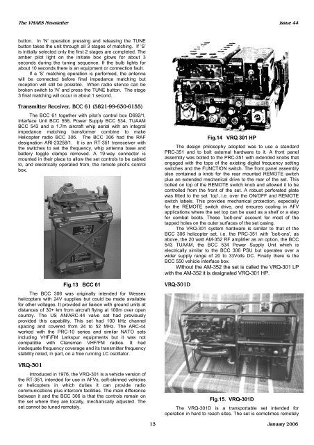
Fig.14 VRQ 301 HP<br />
<strong>The</strong> design philosophy adopted was to use a st<strong>and</strong>ard<br />
<strong>PRC</strong>-<strong>351</strong> <strong>and</strong> to bolt external hardware to it. A front panel<br />
assembly was bolted to the <strong>PRC</strong>-<strong>351</strong> with extended knobs that<br />
engaged with the tops of the existing digital frequency setting<br />
switches <strong>and</strong> the FUNCTION switch. <strong>The</strong> front panel assembly<br />
also contained a knob for the rear mounted REMOTE switch<br />
plus an extended mechanical drive to the rear of the set. This<br />
bolted on top of the REMOTE switch knob <strong>and</strong> allowed it to be<br />
controlled from the front of the set. A robust perforated plate<br />
was fitted to the set `top', i.e. over the ON/OFF <strong>and</strong> REMOTE<br />
switch labels. This provides mechanical protection, especially<br />
for the REMOTE switch drive, <strong>and</strong> ensures cooling in AFV<br />
applications where the set top can be used as a shelf or a step<br />
for combat boots. <strong>The</strong>se `bolt-ons' account for most of the<br />
tapped holes on the outer surfaces of the set casing.<br />
<strong>The</strong> VRQ-301 system hardware is similar to that of the<br />
BCC 306 helicopter set, i.e. the <strong>PRC</strong>-<strong>351</strong> with `bolt-ons', as<br />
above, the 20 watt AM-352 RF amplifier as an option, the BCC<br />
543 TUAAM, the BCC 534 Power Supply Unit which is<br />
electrically similar to the BCC 306 PSU but operates over a<br />
wider supply range of 20 to 33Volts DC. Finally there is the<br />
BCC 550 vehicle interface box.<br />
Without the AM-352 the set is called the VRQ-301 LP<br />
with the AM-352 it is designated VRQ-301 HP.<br />
VRQ-301D<br />
Fig.15. VRQ-301D<br />
<strong>The</strong> VRQ-301D is a transportable set intended for<br />
operation in hard to reach sites. <strong>The</strong> set is sometimes remotely<br />
13 January 2006


