Create successful ePaper yourself
Turn your PDF publications into a flip-book with our unique Google optimized e-Paper software.
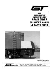
5. PTO Driveline - Disconnect PTO driveline, pull<br />
the two sections apart, apply thin coat of multipurpose<br />
grease to inside of outer (female) sec<br />
tion. Reassemble sections and install. Pull each<br />
section to be sure driveline and shields are<br />
securely connected. Make certain PTO shielding<br />
is in good condition.<br />
6. Gearbox - Add EP80W-90 gear oil as necessary<br />
to bring oil level to check plug on top of housing.<br />
Figure 4-1 Lubrication<br />
(6) Before Each Use<br />
(3) Before Each Use<br />
(4) Before Each Use (5) Before Each Use<br />
(2) Before Each Use<br />
(1) Before Each Use<br />
To remove yoke shield:<br />
Turn slotted head 90° with<br />
screwdriver, remove turn screw<br />
and slide cover back.<br />
Figure 4-2<br />
Blade Nut Removal<br />
WARNING<br />
THE CUTTER CAN FALL FROM HYDRAULIC<br />
SYSTEM FAILURE. TO AVOID SERIOUS<br />
INJURY OR DEATH, SECURELY SUPPORT<br />
CUTTER BEFORE WORKING UNDERNEATH.<br />
4-3 BLADE HOLDER ASSEMBLY<br />
REMOVAL AND INSTALLATION<br />
A. Remove the lower shaft nut and lockwasher.<br />
B.Wearing heavy gloves, grasp blade holder and<br />
pull off tapered shaft. If stuck, align bolt with access<br />
hole in top of cutter deck. Using sledge hammer and<br />
a piece of pipe, strike blade bar. Rotate pan to the<br />
other blade bolt and strike blade bar. Repeat until<br />
blade holder comes off. Care should be taken not to<br />
damage blade bolt threads.<br />
REPLACEMENT<br />
A. Replace blade holder and tighten the lower<br />
shaft nut to 600 ft./lbs. If a torque wrench is not<br />
available, the nut should be tightened with a<br />
wrench having a three foot handle, or a section<br />
of pipe over the wrench handle, if a wrench of<br />
this size is not available.<br />
B. Strike the blade holder several times with a<br />
heavy hammer and retighten lower shaft nut. This<br />
should be repeated several times.<br />
4-4 BLADE REPLACEMENT (Figure 4-2)<br />
It is not necessary to remove the complete blade<br />
holder assembly to replace the blades. Blade bolts<br />
are accessible through a hole in the top of the cutter<br />
deck. Always replace both blades on a spindle using<br />
two blades having the same weight. Use only genuine<br />
<strong>Bush</strong> <strong>Hog</strong> replacement parts.<br />
A. Raise cutter and securely block in position.<br />
1-11/16” Socket<br />
B. Remove nuts from blade bolts using a 1-11/16”<br />
socket through the access hole in the deck.<br />
C. Inspect blade bolt shoulder for wear. Replace<br />
if necessary.<br />
D. Assemble new blades to blade holder using<br />
blade bolts, nuts and lockwashers. Tighten nuts to<br />
450 ft./lbs. Strike blade bolt head with heavy hammer<br />
to seat, then retighten.<br />
E. Check to be sure blades swing 360° freely.<br />
If blades will not swing freely, remove, locate<br />
problem, and repair. Operating cutter when<br />
blades will not swing freely will cause excessive<br />
vibration, damaging implement.<br />
4-5 SLIP CLUTCH OPERATIONAL CHECK<br />
After implement had been stored for 30 days or<br />
more, perform the following operational check:<br />
A. Loosen eight nuts retaining clutch springs 1/3<br />
turn or until spring can be turned with fingers.<br />
B. With tractor at idle speed, engage tractor PTO<br />
drive for 2-3 seconds. Clutch should slip without<br />
11