Electrode Shape and Collector Plate Spacing Effects on ESP - isesp
Electrode Shape and Collector Plate Spacing Effects on ESP - isesp
Electrode Shape and Collector Plate Spacing Effects on ESP - isesp

You also want an ePaper? Increase the reach of your titles
YUMPU automatically turns print PDFs into web optimized ePapers that Google loves.
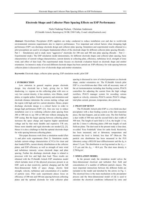
<str<strong>on</strong>g>Electrode</str<strong>on</strong>g> <str<strong>on</strong>g>Shape</str<strong>on</strong>g> <str<strong>on</strong>g>and</str<strong>on</strong>g> <str<strong>on</strong>g>Collector</str<strong>on</strong>g> <str<strong>on</strong>g>Plate</str<strong>on</strong>g> <str<strong>on</strong>g>Spacing</str<strong>on</strong>g> <str<strong>on</strong>g>Effects</str<strong>on</strong>g> <strong>on</strong> <strong>ESP</strong> Performance 111<br />
<str<strong>on</strong>g>Electrode</str<strong>on</strong>g> <str<strong>on</strong>g>Shape</str<strong>on</strong>g> <str<strong>on</strong>g>and</str<strong>on</strong>g> <str<strong>on</strong>g>Collector</str<strong>on</strong>g> <str<strong>on</strong>g>Plate</str<strong>on</strong>g> <str<strong>on</strong>g>Spacing</str<strong>on</strong>g> <str<strong>on</strong>g>Effects</str<strong>on</strong>g> <strong>on</strong> <strong>ESP</strong> Performance<br />
Niels Finderup Nielsen, Christian Anderss<strong>on</strong><br />
(FLSmidth Airtech, Ramsingsvej 30 DK 2500 Valby, E-mail: nfn@flsairtech.com)<br />
Abstract: ElectroStatic Precipitator (<strong>ESP</strong>) suppliers are today c<strong>on</strong>ducted to reduce installati<strong>on</strong> cost <str<strong>on</strong>g>and</str<strong>on</strong>g> due to world-wide<br />
envir<strong>on</strong>mental emissi<strong>on</strong> requirements also to improve performance. Two important <str<strong>on</strong>g>and</str<strong>on</strong>g> critical factors when designing high<br />
performance <strong>ESP</strong>’s are discharge electrode design <str<strong>on</strong>g>and</str<strong>on</strong>g> collector plate spacing. Simulati<strong>on</strong> <str<strong>on</strong>g>and</str<strong>on</strong>g> experimental results obtained in a<br />
pilot precipitator are used to investigate fundamental effects of the electrode shape for different collector plate spacing (Results –<br />
Part 1 – Simulati<strong>on</strong>s) <str<strong>on</strong>g>and</str<strong>on</strong>g> to study more “aggressive” electrodes for 300 mm <str<strong>on</strong>g>and</str<strong>on</strong>g> 500 mm plate spacing (Results – Part 2 –<br />
Experimental study). The <strong>ESP</strong> simulati<strong>on</strong> model dem<strong>on</strong>strates, for different electrode shapes <str<strong>on</strong>g>and</str<strong>on</strong>g> collector plate spacing, basic<br />
characteristics of current-voltage-characteristics, current density at collecting plate, efficiency, turbulence level, strength of i<strong>on</strong>ic<br />
wind, <str<strong>on</strong>g>and</str<strong>on</strong>g> effect of dust load. The experimental study focuses <strong>on</strong> electrode evaluati<strong>on</strong> based <strong>on</strong> electrode shape <str<strong>on</strong>g>and</str<strong>on</strong>g> emitter<br />
orientati<strong>on</strong>. An intensive study of several different electrode shapes has been carried out. <strong>ESP</strong> efficiency for wide spacing between<br />
collector plates is discussed in view of electrode shape <str<strong>on</strong>g>and</str<strong>on</strong>g> emitter orientati<strong>on</strong>.<br />
Keywords: <str<strong>on</strong>g>Electrode</str<strong>on</strong>g> shape, collector plate spacing, <strong>ESP</strong> simulati<strong>on</strong> model, pilot <strong>ESP</strong><br />
0B1 INTRODUCTION<br />
Low emissi<strong>on</strong> in general requires proper electrode<br />
design. Any electrode has a body, giving rise to field<br />
shadowing, i.e. regi<strong>on</strong>s <strong>on</strong> the collecting plate with zero or<br />
very low current density, it has emitters, wire fibulas, small<br />
plates, or regular spikes. Emitter geometry <str<strong>on</strong>g>and</str<strong>on</strong>g> orientati<strong>on</strong> <str<strong>on</strong>g>and</str<strong>on</strong>g><br />
electrode distance determine the cor<strong>on</strong>a starting voltage <str<strong>on</strong>g>and</str<strong>on</strong>g><br />
the regi<strong>on</strong> with high <str<strong>on</strong>g>and</str<strong>on</strong>g> low current densities. Hence, proper<br />
discharge electrode design is a critical factor in order to<br />
design high performance <strong>ESP</strong>’s [1]. Also <strong>on</strong>e way to reduce<br />
installati<strong>on</strong> cost is to widening collector plate spacing from<br />
300 or 400 mm to say 500 or 600 mm without enlarging the<br />
<strong>ESP</strong> casing. But the larger spacing between collecting plates<br />
increases the space charge <str<strong>on</strong>g>and</str<strong>on</strong>g> requires higher operati<strong>on</strong>al<br />
voltage <str<strong>on</strong>g>and</str<strong>on</strong>g> by that more durable <str<strong>on</strong>g>and</str<strong>on</strong>g> expensive T/R sets.<br />
Hence more durable <str<strong>on</strong>g>and</str<strong>on</strong>g> rigid electrodes are needed [2], [3].<br />
Hence it is also a challenge to find the optimal electrode shape<br />
for wide spacing between collecting plates.<br />
This paper discusses work from a simulati<strong>on</strong> model (Part<br />
1) <str<strong>on</strong>g>and</str<strong>on</strong>g> pilot scale experiments (Part 2). Simulati<strong>on</strong> results<br />
include current-voltage characteristics (CVCs) for clean <str<strong>on</strong>g>and</str<strong>on</strong>g><br />
dust loaded <strong>ESP</strong>s, current density distributi<strong>on</strong>s at the collector<br />
plates, <str<strong>on</strong>g>and</str<strong>on</strong>g> <strong>ESP</strong> efficiency as well as strength of i<strong>on</strong>ic wind<br />
<str<strong>on</strong>g>and</str<strong>on</strong>g> turbulence intensity versus electrode shape <str<strong>on</strong>g>and</str<strong>on</strong>g> plate<br />
spacing. Further the discharge electrode shape is related to<br />
processes with low <str<strong>on</strong>g>and</str<strong>on</strong>g> high dust load. These results are<br />
obtained with the FLSmidth Airtech <strong>ESP</strong> simulati<strong>on</strong> model<br />
which includes most of the physical processes present in an<br />
<strong>ESP</strong>, such as dust resistivity, particle charging <str<strong>on</strong>g>and</str<strong>on</strong>g> the full<br />
three-dimensi<strong>on</strong>al fields of space charge, electric field<br />
strength, velocity, turbulence <str<strong>on</strong>g>and</str<strong>on</strong>g> c<strong>on</strong>centrati<strong>on</strong> of a number<br />
of particle sizes. Pilot scale experiments places focus <strong>on</strong><br />
efficiency of 300 mm <str<strong>on</strong>g>and</str<strong>on</strong>g> 500 mm spacing between collecting<br />
plates <str<strong>on</strong>g>and</str<strong>on</strong>g> the optimal electrode for wide collector plate<br />
spacing is discussed in view of critical parameters as electrode<br />
shape, emitter orientati<strong>on</strong> etc. The FLSmidth Airtech pilot<br />
<strong>ESP</strong> is a two-field-<strong>on</strong>e-duct filter with all necessary state of<br />
the art instrumentati<strong>on</strong> including dust feeding system, PIACS<br />
c<strong>on</strong>trollers for adjusting the current from the high voltage<br />
rectifiers, PIACS manager system for recording various<br />
signals as velocity, emissi<strong>on</strong>, PIACS current, PIACS voltage,<br />
total plate current, pressure, temperature, dew point etc.<br />
1B2 PILOT <strong>ESP</strong> SETUP<br />
The FLSmidth Airtech pilot <strong>ESP</strong> is a two-field-<strong>on</strong>e-duct<br />
precipitator with a dust feeding system at the inlet transiti<strong>on</strong><br />
piece, flat dust hoppers, <str<strong>on</strong>g>and</str<strong>on</strong>g> an outlet c<strong>on</strong>e. The first field has<br />
a duct width of 300 mm <str<strong>on</strong>g>and</str<strong>on</strong>g> the sec<strong>on</strong>d field a duct width of<br />
500 mm. The length of each field is 1.8 m, the height 1.5 m,<br />
<str<strong>on</strong>g>and</str<strong>on</strong>g> the 2 times 6 collecting plates (300 mm length) of each<br />
field are plane. The dust used in the present study is lime dust,<br />
so-called ‘Faxe Foderkalk’ (lime for cattle food). Resistivity<br />
has been measured, <str<strong>on</strong>g>and</str<strong>on</strong>g> at laboratory temperature <str<strong>on</strong>g>and</str<strong>on</strong>g><br />
moisture the level is limited, less than 10 9 Ohm·cm. The<br />
particle size distributi<strong>on</strong> has been measured in the FLS<br />
laboratory using a HELOS laser diffractiometer <str<strong>on</strong>g>and</str<strong>on</strong>g> the d 50 is<br />
about 5.3 µm. The distributi<strong>on</strong> is not log-normal as the d 15.9 =<br />
1.25 µm <str<strong>on</strong>g>and</str<strong>on</strong>g> the d 84.1 = 40.4 µm. The dust mass density is<br />
2,700 kg/m³.<br />
2B3 SIMULATION MODEL<br />
In the present study the simulati<strong>on</strong> model solves the<br />
three-dimensi<strong>on</strong>al electrical <str<strong>on</strong>g>and</str<strong>on</strong>g> turbulent flow field <str<strong>on</strong>g>and</str<strong>on</strong>g><br />
c<strong>on</strong>centrati<strong>on</strong> of a number of different particle classes. The<br />
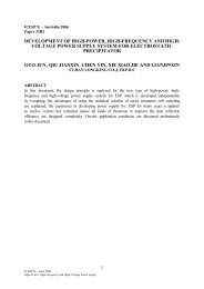
most important interacti<strong>on</strong>s between the different fields are<br />
included in the model <str<strong>on</strong>g>and</str<strong>on</strong>g> sketched by the arrows in Fig. 1.<br />
The electrical force is the main mechanism in the precipitator<br />
process <str<strong>on</strong>g>and</str<strong>on</strong>g> the three-dimensi<strong>on</strong>al model of [4] is used to<br />
calculate the electrical c<strong>on</strong>diti<strong>on</strong>s influenced by i<strong>on</strong>ic <str<strong>on</strong>g>and</str<strong>on</strong>g>
112<br />
11th Internati<strong>on</strong>al C<strong>on</strong>ference <strong>on</strong> Electrostatic Precipitati<strong>on</strong><br />
particle space charge. This model solves simultaneously the<br />
coupled electric <str<strong>on</strong>g>and</str<strong>on</strong>g> current density fields. The electric field<br />
takes into account the influence of i<strong>on</strong>ic c<strong>on</strong>vecti<strong>on</strong> <str<strong>on</strong>g>and</str<strong>on</strong>g><br />
diffusi<strong>on</strong> due to cor<strong>on</strong>a discharge, the presence of particle<br />
space charge (electric field distorti<strong>on</strong>) <str<strong>on</strong>g>and</str<strong>on</strong>g> the effect of dust<br />
resistivity at the collector plates. The weak interacti<strong>on</strong> from<br />
the flow field <strong>on</strong> the electric field, i.e. the current due to<br />
c<strong>on</strong>vecti<strong>on</strong> of charge, is not included. However, the str<strong>on</strong>g<br />
interacti<strong>on</strong> of the electrical field (body force) <strong>on</strong> the flow field<br />
as well as the actual geometry is taken into account as seen<br />
from the induced sec<strong>on</strong>dary flows. The weak interacti<strong>on</strong> from<br />
the particle field <strong>on</strong> the flow field is not included. The<br />
turbulent particle transport c<strong>on</strong>trolled by both electric field<br />
(including particle charging) <str<strong>on</strong>g>and</str<strong>on</strong>g> flow field (fluid particle<br />
dynamics) is modelled by an Eulerian approach due to the<br />
highly coupled problem, i.e. by treating particles as a sec<strong>on</strong>d<br />
c<strong>on</strong>tinuum phase characterized by its c<strong>on</strong>centrati<strong>on</strong>, which<br />
also reduces the computati<strong>on</strong>al effort.<br />
The three-dimensi<strong>on</strong>al electrostatic field between<br />
discharge electrode <str<strong>on</strong>g>and</str<strong>on</strong>g> collector plate in terms of potential<br />
<str<strong>on</strong>g>and</str<strong>on</strong>g> charge density is computed by solving<br />
∇·E = (ρ i +ρ p )/ε 0 , ∇·J = 0 (1)<br />
J = (ρ i b i E – D i ∇ρ i ) + (ρ p b p E – D p ∇ρ p )<br />
where: E= –∇ϕ is the electric field, ϕ the electric potential, ρ i<br />
<str<strong>on</strong>g>and</str<strong>on</strong>g> ρ p the space charge density of gas i<strong>on</strong>s <str<strong>on</strong>g>and</str<strong>on</strong>g> particles,<br />
respectively, ε 0 the electric permittivity, J the current density,<br />
b i <str<strong>on</strong>g>and</str<strong>on</strong>g> b p the mobility of gas i<strong>on</strong>s <str<strong>on</strong>g>and</str<strong>on</strong>g> particles, respectively,<br />
<str<strong>on</strong>g>and</str<strong>on</strong>g> D i <str<strong>on</strong>g>and</str<strong>on</strong>g> D p i<strong>on</strong> <str<strong>on</strong>g>and</str<strong>on</strong>g> particle diffusivity coefficients,<br />
respectively. For a detailed descripti<strong>on</strong> of the FLSmidth<br />
Airtech simulati<strong>on</strong> model including modelling procedure,<br />
coefficient values, geometry, computati<strong>on</strong>al mesh, <str<strong>on</strong>g>and</str<strong>on</strong>g><br />
boundary c<strong>on</strong>diti<strong>on</strong>s is referred to previous papers [4], [5],<br />
[6], [7], [8], [9].<br />
Flow field<br />
Particle C<strong>on</strong>centrati<strong>on</strong> field<br />
Electric field<br />
Fig. 1 Interacti<strong>on</strong> between different fields of the <strong>ESP</strong><br />
simulati<strong>on</strong> model<br />
3B4 EXPERIMENTAL SETUP<br />
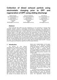
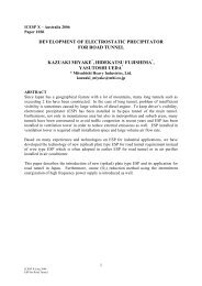
The FLSmidth Airtech pilot <strong>ESP</strong> is shown in Fig. 2. The<br />
air is sucked in through Viled<strong>on</strong> filter mats fitted to the inlet<br />
box. The flow rate generated by the fans running at c<strong>on</strong>stant<br />
rpm is c<strong>on</strong>trolled by a damper in the outlet duct c<strong>on</strong>trolled by<br />
an electromotor. The volume flow rate signal is the static<br />
pressure difference across the outlet c<strong>on</strong>e, having been<br />
calibrated against a pitot-static tube.<br />
As menti<strong>on</strong>ed above the first field of the pilot <strong>ESP</strong> has a<br />
duct width of 300 mm <str<strong>on</strong>g>and</str<strong>on</strong>g> the sec<strong>on</strong>d field a duct width of<br />
500 mm. The length of each field is 1.8 m <str<strong>on</strong>g>and</str<strong>on</strong>g> the height 1.5<br />
m. Having such small fields with a nominal height of 1.5 m,<br />
proper baffeling is of great importance in order to avoid<br />
sneakage above <str<strong>on</strong>g>and</str<strong>on</strong>g> below the electrode system. The top of<br />
the secti<strong>on</strong>s has been closed by horiz<strong>on</strong>tal covers of Tefl<strong>on</strong><br />
<str<strong>on</strong>g>and</str<strong>on</strong>g> the bottom with vertical baffles of Tefl<strong>on</strong>. Likewise,<br />
baffles are inserted between plate curtains <str<strong>on</strong>g>and</str<strong>on</strong>g> compartment<br />
walls.<br />
Fig. 2 FLSmidth Airtech pilot <strong>ESP</strong><br />
The current from the high voltage rectifiers is fed to each<br />
field via trunking <str<strong>on</strong>g>and</str<strong>on</strong>g> PIACS c<strong>on</strong>trollers, type II, c<strong>on</strong>trol the<br />
current settings. HV capacitors ensure an almost pure DC.<br />
<str<strong>on</strong>g>Collector</str<strong>on</strong>g> plates are isolated <str<strong>on</strong>g>and</str<strong>on</strong>g> c<strong>on</strong>nected to ground via<br />
resistances making it possible to measure the current flowing<br />
to each plate-pair (opposite strips are c<strong>on</strong>nected in parallel).<br />
The plates are guided at the lower edge by a rapper bar<br />
insulated from the plates by Acetal plastic. A h<str<strong>on</strong>g>and</str<strong>on</strong>g> operated<br />
hammer is fitted outside, <str<strong>on</strong>g>and</str<strong>on</strong>g> rapping is d<strong>on</strong>e between<br />
measurement series.<br />
The opacity meter, a SICK RM4 transmissiometer, is<br />
sending its light beam from bottom to top of the outlet funnel<br />
<str<strong>on</strong>g>and</str<strong>on</strong>g>, by use of a reflector, back again. A plane 45° mirror is<br />
placed between the SICK m<strong>on</strong>itor <str<strong>on</strong>g>and</str<strong>on</strong>g> the hole in the funnel<br />
bottom, <str<strong>on</strong>g>and</str<strong>on</strong>g> before any recording is started the mirror is<br />
cleaned. Air purging of mirror <str<strong>on</strong>g>and</str<strong>on</strong>g> reflector keeps the optics<br />
clean during measurements. The SICK signal has been<br />
calibrated by gravimetrical measurements.<br />
4B5 RESULTS AND DISCUSSIONS<br />
The results have been divided into two parts. Part 1 is<br />
simulati<strong>on</strong> results c<strong>on</strong>sidering different elements related to the<br />
basic underst<str<strong>on</strong>g>and</str<strong>on</strong>g>ing of <strong>ESP</strong> behaviour for different electrode<br />
shapes <str<strong>on</strong>g>and</str<strong>on</strong>g> collector plate spacing. Part 2 is experimental<br />
results focusing <strong>on</strong> the optimal electrode for wide collector<br />
plate spacing. The setup of the pilot <strong>ESP</strong> described above has<br />
been used for both Part 1 <str<strong>on</strong>g>and</str<strong>on</strong>g> 2 <str<strong>on</strong>g>and</str<strong>on</strong>g> relevant operati<strong>on</strong>al data<br />
are shown in Table 1. Note that the mean particle diameter is<br />
relatively small <str<strong>on</strong>g>and</str<strong>on</strong>g> that the resistivity is relatively low.<br />
CASE<br />
Table 1 Pilot <strong>ESP</strong> operati<strong>on</strong>al data<br />
Pilot <strong>ESP</strong><br />
Field No/plate spacing [mm] 1/300 2/500<br />
UElectrical c<strong>on</strong>diti<strong>on</strong>s:<br />
Current density level [mA/m 2 ]<br />
UFlow c<strong>on</strong>diti<strong>on</strong>s:<br />
Mean bulk velocity V 0 [m/s]<br />
Temperature [ o C]<br />
<strong>ESP</strong> pressure [bar]<br />
0.01-1.0 0.01-1.0<br />
1.3<br />
22<br />
1.0<br />
1.3<br />
22<br />
1.0
<str<strong>on</strong>g>Electrode</str<strong>on</strong>g> <str<strong>on</strong>g>Shape</str<strong>on</strong>g> <str<strong>on</strong>g>and</str<strong>on</strong>g> <str<strong>on</strong>g>Collector</str<strong>on</strong>g> <str<strong>on</strong>g>Plate</str<strong>on</strong>g> <str<strong>on</strong>g>Spacing</str<strong>on</strong>g> <str<strong>on</strong>g>Effects</str<strong>on</strong>g> <strong>on</strong> <strong>ESP</strong> Performance 113<br />
UDust particle c<strong>on</strong>diti<strong>on</strong>s:<br />
Particle mean diameter [μm]<br />
Particle std. deviati<strong>on</strong> [μm]<br />
Number of particle classes<br />
Particle mass density [kg/m 3 ]<br />
Dust load [g/m 3 ]<br />
Particle resistivity [Ω·cm]<br />
5.3<br />
not log nor.<br />
27<br />
2700<br />
1.0<br />
not log nor<br />
27<br />
2700<br />
1.0<br />
10 9<br />
10 9 5.3<br />
5.1 Part 1 – Simulati<strong>on</strong> Results<br />
The simulati<strong>on</strong>s are carried out for field 1 <strong>on</strong>ly since it<br />
focuses <strong>on</strong> basic underst<str<strong>on</strong>g>and</str<strong>on</strong>g>ing <str<strong>on</strong>g>and</str<strong>on</strong>g> due to the fact that the<br />
simulati<strong>on</strong> model is not restricted to 300 mm collector plate<br />
spacing. Three basic types of electrodes, Type-A, Type-B,<br />
<str<strong>on</strong>g>and</str<strong>on</strong>g> Type-C have been studied (Table 2). For Type-A <str<strong>on</strong>g>and</str<strong>on</strong>g><br />
Type-B the emitters are pointing in the axial flow directi<strong>on</strong><br />
(0 o ). For Type-C the emitters are pointing towards the<br />
collecting plate (90 o ).<br />
Table 2 Three type of electrodes used for model simulati<strong>on</strong>s.<br />
d denotes half duct width<br />
<str<strong>on</strong>g>Electrode</str<strong>on</strong>g><br />
Type<br />
pin length<br />
[mm]<br />
pin dist.<br />
from plate<br />
[mm]<br />
pin spacing al<strong>on</strong>g<br />
electrode [mm] <str<strong>on</strong>g>and</str<strong>on</strong>g><br />
orientati<strong>on</strong><br />
Type-A medium d-0 100 , 0 o (round)<br />
Type-B large d-0 100 , 0 o (round)<br />
Type-C large d-17 100 , 90 o (sharp)<br />
Focus has been placed <strong>on</strong> seven different kinds of<br />
results:<br />
• Experimental verificati<strong>on</strong>;<br />
• CVCs versus plate spacing <str<strong>on</strong>g>and</str<strong>on</strong>g> electrode shape;<br />
• Current density distributi<strong>on</strong> at collector plates;<br />
• Efficiency versus cor<strong>on</strong>a power;<br />
• Turbulence intensity versus plate spacing;<br />
• Strength of i<strong>on</strong>ic wind versus plate spacing;<br />
• Effect of dust load.<br />
These items are presented separately below.<br />
Regarding turbulence intensity <str<strong>on</strong>g>and</str<strong>on</strong>g> strength of i<strong>on</strong>ic<br />
wind these parameters are defined as follows. The turbulence<br />
intensity yz = (2 yz /3) 1/2 /U 0 calculated from turbulent<br />
kinetic energy k yz = ½ < uu k k<br />
> yz , <str<strong>on</strong>g>and</str<strong>on</strong>g> the bulk velocity U 0 =<br />
yz .The strength of i<strong>on</strong>ic wind is represented by the mean<br />
value of magnitude of the velocity vector yz . Hence<br />
these two parameters are average values over the cross secti<strong>on</strong><br />
at a given axial positi<strong>on</strong>.<br />
UExperimental verificati<strong>on</strong><br />
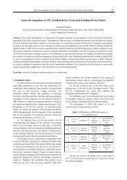
Fig. 3 shows measured <str<strong>on</strong>g>and</str<strong>on</strong>g> computed current-voltage<br />
characteristics (CVCs) for a clean <strong>ESP</strong> with Type-A<br />
electrodes <str<strong>on</strong>g>and</str<strong>on</strong>g> collector plate spacing of 300 <str<strong>on</strong>g>and</str<strong>on</strong>g> 500 mm.<br />
It is noted that the cor<strong>on</strong>a start potential is an input<br />
parameter for the computati<strong>on</strong>al model. This parameter has<br />
been fitted to the experimental data. For dust loaded gases<br />
other parameters of influence for CVCs are particle mass<br />
density, gas temperature, <str<strong>on</strong>g>and</str<strong>on</strong>g> pressure. These parameters are<br />
well c<strong>on</strong>trolled in a laboratory study but not always accessible<br />
for full scale studies. Anyway the computed CVCs for clean<br />
gases fits well with experimental values especially in the<br />
current density range of interest say 0.1 to 0.6 mA/m 2 . The<br />
predicted cor<strong>on</strong>a start potential for the different spacing<br />
between collector plates <str<strong>on</strong>g>and</str<strong>on</strong>g> electrode types will be used in<br />
the present study for the dust loaded <strong>ESP</strong>s.<br />
Current density [mA/m²]<br />
1.000<br />
0.100<br />
0.010<br />
300 mm spacing<br />
500 mm spacing<br />
EXP - Type-A (300mm)<br />
CFD - Type-A (300 mm)<br />
EXP - Type-A (500mm)<br />
CFD - Type-A (500 mm)<br />
0.001<br />
20 30 40 50 60 70 80 90 100 110 120 130 140 150<br />
Voltage [kV]<br />
Fig. 3 Measured (symbols) <str<strong>on</strong>g>and</str<strong>on</strong>g> computed (solid coloured<br />
lines) CVCs for different Type-A electrode with 300 <str<strong>on</strong>g>and</str<strong>on</strong>g> 500<br />
mm spacing between collecting plates. Clean pilot <strong>ESP</strong> setup<br />
UCVCs versus plate spacing <str<strong>on</strong>g>and</str<strong>on</strong>g> electrode shape<br />
Calculated CVC’s for the Type-A, Type-B <str<strong>on</strong>g>and</str<strong>on</strong>g> Type-C<br />
electrodes are shown in Fig. 4.<br />
Current density [mA/m²]<br />
Current density [mA/m²]<br />
Current density [mA/m²]<br />
1.000<br />
0.100<br />
0.010<br />
0.001<br />
1.000<br />
0.100<br />
0.010<br />
0.001<br />
1.000<br />
0.100<br />
0.010<br />
0.001<br />
300mm<br />
400mm<br />
500mm<br />
600mm<br />
Type-A<br />
Type-B<br />
Type-C<br />
10 20 30 40 50 60 70 80 90 100 110 120 130 140<br />
Voltage [kV]
114<br />
11th Internati<strong>on</strong>al C<strong>on</strong>ference <strong>on</strong> Electrostatic Precipitati<strong>on</strong><br />
Fig. 4 Computed CVCs for Type-A, Type-B, <str<strong>on</strong>g>and</str<strong>on</strong>g> Type-C<br />
electrodes of the pilot <strong>ESP</strong><br />
Note the fairly high cor<strong>on</strong>a <strong>on</strong>set voltage of the Type-A<br />
<str<strong>on</strong>g>and</str<strong>on</strong>g> Type-B electrodes (round emitters) <str<strong>on</strong>g>and</str<strong>on</strong>g> the low cor<strong>on</strong>a<br />
<strong>on</strong>set voltage of the Type-C electrode (sharp emitter). For all<br />
electrodes we also notice higher cor<strong>on</strong>a <strong>on</strong>set voltage for<br />
larger plate spacing. As expected the narrower spacing<br />
between collecting plates the higher the current density at the<br />
same operati<strong>on</strong>al voltage. Hence, the narrower spacing<br />
between discharge electrode <str<strong>on</strong>g>and</str<strong>on</strong>g> collector plate leads to the<br />
str<strong>on</strong>g electric field near the cor<strong>on</strong>a wire <str<strong>on</strong>g>and</str<strong>on</strong>g> by that cor<strong>on</strong>a<br />
current is easily generated.<br />
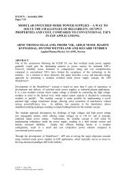
UCurrent density distributi<strong>on</strong> at collector plates<br />
The plot of Fig. 5(a) shows the current density<br />
distributi<strong>on</strong> <strong>on</strong> the collecting surface for Type-A, Type-B, <str<strong>on</strong>g>and</str<strong>on</strong>g><br />
Type-C electrodes at mean current density of 0.30 mA/m².<br />
Fig. 6(a) shows the efficiency for Type-A, Type-B, <str<strong>on</strong>g>and</str<strong>on</strong>g><br />
Type-C electrodes at collector plate spacing of 300 mm, 400<br />
mm, 500 mm <str<strong>on</strong>g>and</str<strong>on</strong>g> 600 mm.<br />
Efficiency [%]<br />
100<br />
90<br />
80<br />
70<br />
60<br />
50<br />
100<br />
Type-A<br />
Type-A<br />
90<br />
Type-B<br />
Type-C<br />
Efficiency [%]<br />
80<br />
70<br />
Fig. 5(a) Current density distributi<strong>on</strong> <strong>on</strong> plates between first<br />
<str<strong>on</strong>g>and</str<strong>on</strong>g> sec<strong>on</strong>d electrode for Type-A, Type-B, <str<strong>on</strong>g>and</str<strong>on</strong>g> Type-C<br />
electrodes at 300 mm spacing <str<strong>on</strong>g>and</str<strong>on</strong>g> mean current density of 0.3<br />
mA/m 2 . Vertical black line is electrode body <str<strong>on</strong>g>and</str<strong>on</strong>g> lower<br />
boundary is emitter centre line<br />
60<br />
50<br />
100<br />
90<br />
Type-B<br />
For comparis<strong>on</strong> Fig. 5(b) shows the current density<br />
distributi<strong>on</strong> for Type-A electrode at collector plate spacing of<br />
300 mm, 400 mm, 500 mm <str<strong>on</strong>g>and</str<strong>on</strong>g> 600 mm <str<strong>on</strong>g>and</str<strong>on</strong>g> at mean current<br />
density of 0.30 mA/m².<br />
300 mm<br />
400 mm<br />
500 mm<br />
600 mm<br />
Fig.5(b) Current density distributi<strong>on</strong> <strong>on</strong> the plate for Type-A<br />
electrode at 300 nm, 400 nm, 500 nm <str<strong>on</strong>g>and</str<strong>on</strong>g> 600 mm spacing at<br />
mean current density of 0.3 mA/m 2 . Vertical black line is<br />
electrode body <str<strong>on</strong>g>and</str<strong>on</strong>g> lower boundary is emitter centre line<br />
Type-A <str<strong>on</strong>g>and</str<strong>on</strong>g> Type-C electrodes have almost identical<br />
areas with low current density (below 0.1 mA/m 2 ) while<br />
Type-B electrode has a larger area with low current density<br />
(Fig. 5(a)). Further, as expected, clearly peak current density<br />
is decreasing for increasing spacing between collecting plates<br />
(Fig. 5(b)).<br />
Efficiency versus cor<strong>on</strong>a power<br />
Efficiency [%]<br />
80<br />
70<br />
60<br />
50<br />
Type-C<br />
0 10 20 30 40 50 60 70 80 90 100 110120130 140150<br />
Cor<strong>on</strong>a power [W/m 3 ]<br />
Fig. 6(a) Efficiency versus cor<strong>on</strong>a power for Type-A, Type-<br />
B, <str<strong>on</strong>g>and</str<strong>on</strong>g> Type-C electrodes at plate spacing of 300 nm, 400<br />
nm, 500 nm <str<strong>on</strong>g>and</str<strong>on</strong>g> 600 mm<br />
As expected <strong>ESP</strong> collecti<strong>on</strong> efficiency increases with<br />
increasing cor<strong>on</strong>a power. It can also be seen that the<br />
efficiency slightly decreases for increasing spacing between<br />
the collector plates for Type-A <str<strong>on</strong>g>and</str<strong>on</strong>g> Type-B electrodes while<br />
for Type-C electrode the efficiency is independent of plate<br />
spacing.<br />
Fig. 6(b) shows the efficiency for the 3 different<br />
electrodes <strong>on</strong> the same plot but <strong>on</strong>ly for collector plate<br />
spacing of 300 nm <str<strong>on</strong>g>and</str<strong>on</strong>g> 600 mm. The present investigati<strong>on</strong><br />
indicates that Type-B electrode is the optimal electrode for<br />
300 mm spacing between the collecting plates. Note however
<str<strong>on</strong>g>Electrode</str<strong>on</strong>g> <str<strong>on</strong>g>Shape</str<strong>on</strong>g> <str<strong>on</strong>g>and</str<strong>on</strong>g> <str<strong>on</strong>g>Collector</str<strong>on</strong>g> <str<strong>on</strong>g>Plate</str<strong>on</strong>g> <str<strong>on</strong>g>Spacing</str<strong>on</strong>g> <str<strong>on</strong>g>Effects</str<strong>on</strong>g> <strong>on</strong> <strong>ESP</strong> Performance 115<br />
that there is some scatter <strong>on</strong> the curve for high cor<strong>on</strong>a power.<br />
For 600 mm spacing Type-A <str<strong>on</strong>g>and</str<strong>on</strong>g> Type-B are equally good.<br />
Type-C electrode has the lowest efficiency for all collector<br />
plate spacing.<br />
Efficiency [%]<br />
Efficiency [%]<br />
100<br />
90<br />
80<br />
70<br />
60<br />
50<br />
Type-B<br />
Type-A<br />
300 mm collector plate spacing<br />
Cor<strong>on</strong>a power [W/m 3 ]<br />
Fig. 6(b) Efficiency versus cor<strong>on</strong>a power for Type-A, Type-<br />
B, <str<strong>on</strong>g>and</str<strong>on</strong>g> Type-C electrodes at collector plate spacing of 300 nm<br />
<str<strong>on</strong>g>and</str<strong>on</strong>g> 600 mm<br />
Turbulence intensity versus plate spacing<br />
Calculated values of turbulence intensity (see definiti<strong>on</strong><br />
above) are shown in Fig. 7 for Type-A, Type-B, <str<strong>on</strong>g>and</str<strong>on</strong>g> Type-C<br />
electrodes. All data <strong>on</strong> Fig. 7 are at identical mean current<br />
density of J m = 0.3 mA/m 2 but note that the efficiency for<br />
Type-A, Type-B, <str<strong>on</strong>g>and</str<strong>on</strong>g> Type-C are η = 84%, η = 71%, <str<strong>on</strong>g>and</str<strong>on</strong>g> η =<br />
70%, respectively. In general the turbulence intensity is<br />
almost identical for the different type of electrodes <str<strong>on</strong>g>and</str<strong>on</strong>g> further<br />
independent of spacing between collector plates.<br />
Mean turbulence intensity [%]<br />
100<br />
90<br />
80<br />
70<br />
60<br />
50<br />
20<br />
18<br />
16<br />
14<br />
12<br />
10<br />
8<br />
6<br />
4<br />
2<br />
0<br />
Type-C<br />
Type-C<br />
Type-B<br />
Type-A<br />
600 mm collector plate spacing<br />
0 10 20 30 40 50 60 70 80 90 100110120130140150<br />
Type-A<br />
Type-B<br />
Type-C<br />
250 300 350 400 450 500 550 600 650<br />
<str<strong>on</strong>g>Collector</str<strong>on</strong>g> plate spacing<br />
Fig. 7 Mean turbulence intensity versus collector plate<br />
spacing for Type-A, Type-B, <str<strong>on</strong>g>and</str<strong>on</strong>g> Type-C electrodes<br />
Strength of i<strong>on</strong>ic wind versus plate spacing<br />
Fig. 8 shows the mean strength of i<strong>on</strong>ic wind (see<br />
definiti<strong>on</strong> above) for Type-A, Type-B, <str<strong>on</strong>g>and</str<strong>on</strong>g> Type-C electrodes.<br />
Mean strength of i<strong>on</strong>ic wind [m/s]<br />
0.20<br />
0.15<br />
0.10<br />
0.05<br />
0.00<br />
Type-A<br />
Type-B<br />
Type-C<br />
250 300 350 400 450 500 550 600 650<br />
<str<strong>on</strong>g>Collector</str<strong>on</strong>g> plate spacing<br />
Fig. 8 Mean strength of i<strong>on</strong>ic wind versus collector plate<br />
spacing for Type-A, Type-B, <str<strong>on</strong>g>and</str<strong>on</strong>g> Type-C electrodes<br />
Identical trends as for the mean turbulence intensity are<br />
observed. The mean strength of i<strong>on</strong>ic wind is almost identical<br />
for the different type of electrodes <str<strong>on</strong>g>and</str<strong>on</strong>g> further independent of<br />
spacing between collector plates. However calculati<strong>on</strong>s have<br />
shown that the staggered emitter arrangement, compared to<br />
the present n<strong>on</strong>-staggered, has much lower mean strength of<br />
i<strong>on</strong>ic wind but almost the same level of mean turbulence<br />
intensity.<br />
Effect of dust load<br />
In general there is a large difference between low <str<strong>on</strong>g>and</str<strong>on</strong>g><br />
high dust load. For low load, say 1 g/m 3 , the particle space<br />
charge is fairly low requiring moderate operati<strong>on</strong>al voltage for<br />
a given mean current density while for high dust load, say 10<br />
g/m 3 , the particle space charge is high requiring high<br />
operati<strong>on</strong>al voltage for a given mean current density. Fig. 9<br />
shows CVC’s for low <str<strong>on</strong>g>and</str<strong>on</strong>g> high dust load <str<strong>on</strong>g>and</str<strong>on</strong>g> plate spacing of<br />
300 nm <str<strong>on</strong>g>and</str<strong>on</strong>g> 500 mm in both cases. In this case <strong>on</strong>ly Type-A<br />
electrode has been used.<br />
Current density [mA/m²]<br />
1.000<br />
0.100<br />
0.010<br />
0.001<br />
300mm-1g<br />
300mm-10g<br />
500mm-1g<br />
500mm-10g<br />
Type-A<br />
10 20 30 40 50 60 70 80 90 100 110 120 130 140<br />
Voltage [kV]
116<br />
11th Internati<strong>on</strong>al C<strong>on</strong>ference <strong>on</strong> Electrostatic Precipitati<strong>on</strong><br />
Fig. 9 CVC’s for low (1g/m 3 ) <str<strong>on</strong>g>and</str<strong>on</strong>g> high (10g/m 3 ) dust load<br />
<str<strong>on</strong>g>and</str<strong>on</strong>g> 300 nm <str<strong>on</strong>g>and</str<strong>on</strong>g> 500 mm collector plate spacing. Type-A<br />
electrode<br />
As expected higher dust load (or larger plate spacing)<br />
requires higher operati<strong>on</strong>al voltage for a given mean current<br />
density. Investigating the efficiency versus cor<strong>on</strong>a power for<br />
high dust load we obtain e.g. for 300 mm plate spacing<br />
efficiency η = 94.4% <str<strong>on</strong>g>and</str<strong>on</strong>g> cor<strong>on</strong>a power P=72.6 W/m 3 <str<strong>on</strong>g>and</str<strong>on</strong>g> for<br />
500 mm plate spacing efficiency η = 95.3% for cor<strong>on</strong>a power<br />
P=86.0 W/m 3 both at equal mean current density of 0.3<br />
mA/m 2 but at operati<strong>on</strong>al voltage of 72.6 kV <str<strong>on</strong>g>and</str<strong>on</strong>g> 144.8 kV for<br />
300 nm <str<strong>on</strong>g>and</str<strong>on</strong>g> 500 mm spacing, respectively.<br />
For low dust load the mean current density at each<br />
collector plate is identical downstream the <strong>ESP</strong>. But for high<br />
dust load the mean current density at the first collector plate is<br />
low due to high particle space charge <str<strong>on</strong>g>and</str<strong>on</strong>g> opposite <strong>on</strong> the last<br />
plate where the mean current density is high due to lower<br />
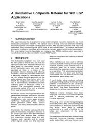
particle space charge. Fig. 10 shows the current density<br />
distributi<strong>on</strong> between first <str<strong>on</strong>g>and</str<strong>on</strong>g> sec<strong>on</strong>d electrode for low <str<strong>on</strong>g>and</str<strong>on</strong>g><br />
high load (upper <str<strong>on</strong>g>and</str<strong>on</strong>g> middle figures) as well as <strong>on</strong>e full field<br />
at high load (lower figure). Clearly, as expected, the mean<br />
distributi<strong>on</strong> <strong>on</strong> each plate changes downstream the <strong>ESP</strong>.<br />
Fig. 10 Current density distributi<strong>on</strong> <strong>on</strong> collector plate<br />
between first <str<strong>on</strong>g>and</str<strong>on</strong>g> sec<strong>on</strong>d electrode for low <str<strong>on</strong>g>and</str<strong>on</strong>g> high dust load<br />
(upper <str<strong>on</strong>g>and</str<strong>on</strong>g> middle figures) <str<strong>on</strong>g>and</str<strong>on</strong>g> downstream field 1 for high<br />
dust load (lower figure). Mean current density is 0.3 mA/m 2<br />
in both cases. Type-A electrode<br />
Figs. 11 <str<strong>on</strong>g>and</str<strong>on</strong>g> 12 show the current density (Fig. 11) <str<strong>on</strong>g>and</str<strong>on</strong>g><br />
particle space charge (Fig. 12) versus <strong>ESP</strong> length for low <str<strong>on</strong>g>and</str<strong>on</strong>g><br />
high dust load.<br />
Current density at plate [mA/m 2 ]<br />
0.60<br />
0.55<br />
0.50<br />
0.45<br />
0.40<br />
0.35<br />
0.30<br />
0.25<br />
0.20<br />
0.15<br />
0.10<br />
0.05<br />
0.00<br />
Dust load of 1 g/m3<br />
Dust load of 10 g/m3<br />
0.0 0.3 0.6 0.9 1.2 1.5 1.8<br />
<strong>ESP</strong> secti<strong>on</strong> length [m]<br />
Fig. 11 Current density <strong>on</strong> plate downstream field 1 at low<br />
<str<strong>on</strong>g>and</str<strong>on</strong>g> high dust load. Mean current density is 0.3 mA/m 2 .<br />
Type-A electrode<br />
Clearly, for high dust load, the current density increases<br />
<str<strong>on</strong>g>and</str<strong>on</strong>g> the particle space charge decreases downstream the <strong>ESP</strong><br />
clearly indicating trends discussed above.<br />
Particle space charge [μC/m 3 ]<br />
30<br />
25<br />
20<br />
15<br />
10<br />
5<br />
0<br />
Dust load of 1 g/m3<br />
Dust load of 10 g/m3<br />
0.0 0.3 0.6 0.9 1.2 1.5 1.8<br />
<strong>ESP</strong> secti<strong>on</strong> length [m]<br />
Fig. 12 Particle space charge downstream field 1 at low <str<strong>on</strong>g>and</str<strong>on</strong>g><br />
high dust load. Mean current density is 0.3 mA/m 2<br />
Type-A electrode<br />
5.2 Part 2 – Experimental Results<br />
The simulati<strong>on</strong> results above indicates the need for<br />
investigating more “aggressive” type of electrodes with sharp<br />
emitters which could be useful for wide spacing between<br />
collecting plates. It turned out that the simulati<strong>on</strong> model<br />
became unstable for some very aggressive electrodes with<br />
emitters pointing towards the collecting plate. Hence the pilot<br />
<strong>ESP</strong> is used for this study. 300 mm (field 1) <str<strong>on</strong>g>and</str<strong>on</strong>g> 500 mm<br />
(field 2) spacing between collecting plates have been studied.<br />
For both plate spacing seven different types of electrodes,<br />
including Type-A <str<strong>on</strong>g>and</str<strong>on</strong>g> Type-C from the simulati<strong>on</strong> study,<br />
have been investigated (Table 3). Hence we have five new<br />
electrodes. For Type-A, Type-D the emitters are pointing in<br />
the axial flow directi<strong>on</strong> (0 o ). For Type-C, Type-E, Type-F,<br />
Type-G, <str<strong>on</strong>g>and</str<strong>on</strong>g> Type-H the emitters are pointing towards the<br />
collecting plate (90 o ). Also note the different distances to the<br />
collecting plate for the different electrodes given in Table 3.<br />
Table 3 Seven type of electrodes used for experimental<br />
investigati<strong>on</strong> in pilot <strong>ESP</strong>. d denotes half duct width<br />
<str<strong>on</strong>g>Electrode</str<strong>on</strong>g><br />
Type<br />
pin length<br />
[mm]<br />
pin dist.<br />
from plate<br />
[mm]<br />
pin spacing al<strong>on</strong>g<br />
electrode [mm] <str<strong>on</strong>g>and</str<strong>on</strong>g><br />
orientati<strong>on</strong><br />
Type-A medium d-0 100 , 0 o (round)<br />
Type-C large d-17 100 , 90 o (sharp)<br />
Type-D short d-0 76 , 0 o (sharp)<br />
Type-E short d-13 76 , 90 o (sharp)<br />
Type-F large d-43 100 , 90 o (sharp)<br />
Type-G medium d-25 110 , 90 o (sharp)<br />
Type-H medium d-29 110 , 90 o (sharp)
<str<strong>on</strong>g>Electrode</str<strong>on</strong>g> <str<strong>on</strong>g>Shape</str<strong>on</strong>g> <str<strong>on</strong>g>and</str<strong>on</strong>g> <str<strong>on</strong>g>Collector</str<strong>on</strong>g> <str<strong>on</strong>g>Plate</str<strong>on</strong>g> <str<strong>on</strong>g>Spacing</str<strong>on</strong>g> <str<strong>on</strong>g>Effects</str<strong>on</strong>g> <strong>on</strong> <strong>ESP</strong> Performance 117<br />
Efficiency<br />
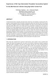
Fig. 13 shows the emissi<strong>on</strong> results from all seven<br />
electrodes presented here as penetrati<strong>on</strong> versus specifik work.<br />
Penetrati<strong>on</strong> is defined as emissi<strong>on</strong> based <strong>on</strong> the opacity meter<br />
reading divided by the inlet loading.<br />
The results are shown for 300 mm collector plate spacing<br />
(results from field 1) <str<strong>on</strong>g>and</str<strong>on</strong>g> for 500 mm spacing (results from<br />
field 2) <str<strong>on</strong>g>and</str<strong>on</strong>g> both at 1.3 m/s mean bulk velocity (see Table 1<br />
for other operati<strong>on</strong>al data).<br />
Penetrati<strong>on</strong> [ %]<br />
Penetrati<strong>on</strong> [%]<br />
12<br />
10<br />
8<br />
6<br />
4<br />
2<br />
0<br />
25<br />
20<br />
15<br />
10<br />
5<br />
0<br />
300 mm spacing<br />
500 mm spacing<br />
Type-A<br />
Type-C<br />
Type-D<br />
Type-E<br />
Type-F<br />
Type-G<br />
Type-H<br />
0 50 100 150 200 250<br />
Specifik work [J/m 3 ]<br />
Type-A<br />
Type-C<br />
Type-D<br />
Type-E<br />
Type-F<br />
Type-G<br />
Type-H<br />
Fig.13 Penetrati<strong>on</strong> versus specific work for seven different<br />
electrodes (Table 3) at plate spacing of 300 (upper) <str<strong>on</strong>g>and</str<strong>on</strong>g> 500<br />
mm (lower)<br />
For 300 mm spacing Type-D is the better electrode<br />
however closely followed by Type-A. Comparing Type-D<br />
(emitters in flow directi<strong>on</strong>) with Type-E (same as Type-D but<br />
emitter towards collecting plate) clearly Type-D is the better<br />
electrode. For 500 mm spacing it is evident that the blunt<br />
Type-A electrode as a whole gives the lowest penetrati<strong>on</strong>,<br />
most likely because the electric field at the plate surface is the<br />
highest. The more aggressive the electrode is, the higher the<br />
penetrati<strong>on</strong>.<br />
<str<strong>on</strong>g>Electrode</str<strong>on</strong>g> evaluati<strong>on</strong><br />
If we look more closely at the results at include both<br />
emissi<strong>on</strong> (penetrati<strong>on</strong>) <str<strong>on</strong>g>and</str<strong>on</strong>g> migrati<strong>on</strong> velocity an evaluati<strong>on</strong> of<br />
the electrodes ends up with Table 4 for 300 mm spacing <str<strong>on</strong>g>and</str<strong>on</strong>g><br />
Table 5 for 500 mm spacing. This investigati<strong>on</strong> indicates that<br />
for 300 mm spacing Type-D (aggressive electrode with<br />
emitters in flow directi<strong>on</strong>) is the better electrode <str<strong>on</strong>g>and</str<strong>on</strong>g> for 500<br />
mm spacing Type-A (blunt electrode with emitters in the flow<br />
directi<strong>on</strong>) is the better electrode. The electrodes fall in three<br />
main groups. The first is the best <str<strong>on</strong>g>and</str<strong>on</strong>g> is little aggressive for<br />
300 mm spacing <str<strong>on</strong>g>and</str<strong>on</strong>g> blunt for 500 mm spacing requiring high<br />
operati<strong>on</strong> voltage. The middle group is middle aggressive<br />
electrodes, <str<strong>on</strong>g>and</str<strong>on</strong>g> the last group c<strong>on</strong>tains the most aggressive<br />
electrodes.<br />
Table 4 <str<strong>on</strong>g>Electrode</str<strong>on</strong>g> evaluati<strong>on</strong> for 300 mm spacing<br />
between collector plates<br />
Type-D Type-A Type-E Type-C Type-F Type-G Type-H<br />
Best Acceptable Worst<br />
Table 5 <str<strong>on</strong>g>Electrode</str<strong>on</strong>g> evaluati<strong>on</strong> for 500 mm spacing between<br />
collector plates<br />
Type-A Type-C Type-D Type-E Type-H Type-G Type-F<br />
Best Acceptable Worst<br />
5B6 CONCLUSIONS<br />
In c<strong>on</strong>clusi<strong>on</strong> the present paper has shown the<br />
capabilities of both the FLSmidth Airtech <strong>ESP</strong> simulati<strong>on</strong><br />
model <str<strong>on</strong>g>and</str<strong>on</strong>g> the pilot <strong>ESP</strong>. The simulati<strong>on</strong> model has<br />
dem<strong>on</strong>strated that it can predict parameters that is difficult to<br />
measure even in a laboratory pilot model setup. The<br />
simulati<strong>on</strong> results, investigating three different electrodes<br />
Type-A, Type-B, <str<strong>on</strong>g>and</str<strong>on</strong>g> Type-C shows, as expected, that the<br />
narrower spacing between collecting plates the higher the<br />
current density at the same operati<strong>on</strong>al voltage. No clear<br />
corelati<strong>on</strong> between <strong>ESP</strong> efficiency <str<strong>on</strong>g>and</str<strong>on</strong>g> current density<br />
distributi<strong>on</strong> at the collecting plates for the different electrodes<br />
was found. However, it should be noted that attempts to<br />
differentiate between the different electrodes <strong>on</strong>ly has a<br />
meaning if the dust load is high as illustrated in the present<br />
study. At low dust load the mean current density at each<br />
collector plate is at a c<strong>on</strong>stant level downstream the <strong>ESP</strong>.<br />
Further it was dem<strong>on</strong>strated that the most efficient electrode<br />
shape for both 300 mm <str<strong>on</strong>g>and</str<strong>on</strong>g> 600 mm spacing was a “l<strong>on</strong>g”<br />
electrode with round emitters (blunt electrode type) pointing<br />
in the flow directi<strong>on</strong> (Type-B electrode). Also, the simulati<strong>on</strong>s<br />
indicates that both the turbulence intensity <str<strong>on</strong>g>and</str<strong>on</strong>g> the strength of<br />
i<strong>on</strong>ic wind seems to be almost identical for the different type<br />
of electrodes <str<strong>on</strong>g>and</str<strong>on</strong>g> further independent of spacing between<br />
collector plates. Finally the simulati<strong>on</strong> model dem<strong>on</strong>strated<br />
that high dust load, or larger plate spacing, requires high<br />
operati<strong>on</strong>al voltage for a given mean current density, as<br />
expected, <str<strong>on</strong>g>and</str<strong>on</strong>g> that for high dust load the mean current density<br />
at the first collector plate is low due to high particle space
118<br />
11th Internati<strong>on</strong>al C<strong>on</strong>ference <strong>on</strong> Electrostatic Precipitati<strong>on</strong><br />
charge <str<strong>on</strong>g>and</str<strong>on</strong>g> opposite <strong>on</strong> the last plate where the mean current<br />
density is high due to lower particle space charge. The<br />
experimental results investigating several different electrodes<br />
clearly dem<strong>on</strong>strated that the most efficient electrode is <strong>on</strong>e<br />
with the emitters pointing in the flow directi<strong>on</strong>. Futrher it<br />
seems that a sharp emitter tip (Type-D; short little aggressive<br />
electrode type) is slightly more efficient for 300 mm plate<br />
spacing but that a round emitter tip (Type-A; medium l<strong>on</strong>g<br />
blunt electrode type) is clearly more efficient for 500 mm<br />
plate spacing. Note that the electrode shape of Type-A <str<strong>on</strong>g>and</str<strong>on</strong>g><br />
Type-B of the simulati<strong>on</strong> study is similar but with different<br />
emitter length. Anyway the experimental study clearly shows<br />
that aggressive electrodes are not preferable for wide spacing<br />
between collecing plates <str<strong>on</strong>g>and</str<strong>on</strong>g> in any case high operati<strong>on</strong>al<br />
voltage is required resulting in expensive T/R sets. However<br />
further analysis is required in order to obtain a final<br />
c<strong>on</strong>clusi<strong>on</strong>.<br />
6BREFERENCES<br />
1. Jaworek, A, Krupa, A & Czech, T., Modern electrostatic<br />
devices <str<strong>on</strong>g>and</str<strong>on</strong>g> methods for exhaust gas cleaning: A brief<br />
review, J. Electrostatics, 65 (2007), 133-155.<br />
2. Darby, K., <str<strong>on</strong>g>Plate</str<strong>on</strong>g> spacing effect <strong>on</strong> precipitator<br />
performance. Proceedings of sec<strong>on</strong>d Internati<strong>on</strong>al<br />
C<strong>on</strong>ference <strong>on</strong> Electrostatic Precipitati<strong>on</strong>, November<br />
1984, Kyoto, Japan, 376-383.<br />
3. Kim, Y.J., Je<strong>on</strong>g, S.H., H<strong>on</strong>g, W.S.Cho, S.S. <str<strong>on</strong>g>and</str<strong>on</strong>g> Ham,<br />
B.H., Effect of the plate spacing <str<strong>on</strong>g>and</str<strong>on</strong>g> disharge electrode<br />
shape <strong>on</strong> the efficiency of wide plate spacing electrostatic<br />
precipitator. Proceedings of Seventh Internati<strong>on</strong>al<br />
C<strong>on</strong>ference <strong>on</strong> Electrostatic Precipitati<strong>on</strong>, September 20-<br />
25, 1998, Ky<strong>on</strong>gju, Korea, 590-595.<br />
4. Zamany, J., 1992, Modelling of particle transport in<br />
Commercial Electrostatic Precipitators, Ph.D Thesis,<br />
ATV EF 316, Technical University of Denmark <str<strong>on</strong>g>and</str<strong>on</strong>g> FLS<br />
Airtech A/S (formerly FLS miljø a/s).<br />
5. Zamany, J., 1995a, Numerical modeling of electrodynamic<br />
c<strong>on</strong>diti<strong>on</strong>s influenced by particle space charge <str<strong>on</strong>g>and</str<strong>on</strong>g><br />
resistivity in electrostatic precipitators of complex<br />
geometry for industrial applicati<strong>on</strong>s, Inst Phys C<strong>on</strong>f Ser<br />
No 143: 357-362.<br />
6. Zamany, J., 1995b, Numerical modeling of electrodynamic<br />
c<strong>on</strong>diti<strong>on</strong>s influenced by particle space charge <str<strong>on</strong>g>and</str<strong>on</strong>g><br />
resistivity in electrostatic precipitators of complex<br />
geometry for industrial applicati<strong>on</strong>s, FLS Airtech A/S<br />
(formerly FLS miljø) Internal report, FLS Airtech,<br />
Valby, Denmark.<br />
7. Akoh, E. & Nielsen, N.F., 2000, EFP-2000: Electrostatic<br />
Precipitati<strong>on</strong>–Reducti<strong>on</strong> of Emissi<strong>on</strong> <str<strong>on</strong>g>and</str<strong>on</strong>g> Energy<br />
C<strong>on</strong>sumpti<strong>on</strong>, Software Specificati<strong>on</strong>, FORCE Technology<br />
(formerly DMI) report: TN.2000878, FORCE<br />
Technology, Lyngby, Denmark.<br />
8. Lind, L., Nielsen, N.F., Larsen, P.S., Hove, E.A., 2004,<br />
Simulati<strong>on</strong> of particle transport in electrostatic precipitators,<br />
Proceedings of 9th. Internati<strong>on</strong>al C<strong>on</strong>ference <strong>on</strong><br />
Electrostatic Precipitati<strong>on</strong>, May. 17-21, 2004, Mpumalanga,<br />
South Africa, Paper A24.<br />
9. Nielsen, N.F., Larsen, P.S., Löfström, C, 2006,<br />
Sec<strong>on</strong>dary flows <str<strong>on</strong>g>and</str<strong>on</strong>g> turbulence for staggered <str<strong>on</strong>g>and</str<strong>on</strong>g> n<strong>on</strong>staggered<br />
electrode emitters. Proceedings of 10th.<br />
Internati<strong>on</strong>al C<strong>on</strong>ference <strong>on</strong> Electrostatic Precipitati<strong>on</strong>,<br />
June. 25-29, 2006, Cairns, Australia, Paper 2A3.