ETU02-MUX/Plus User Manual - CTC Union Technologies Co.,Ltd.
ETU02-MUX/Plus User Manual - CTC Union Technologies Co.,Ltd.
ETU02-MUX/Plus User Manual - CTC Union Technologies Co.,Ltd.

You also want an ePaper? Increase the reach of your titles
YUMPU automatically turns print PDFs into web optimized ePapers that Google loves.
<strong>ETU02</strong>-<strong>MUX</strong>/<strong>Plus</strong><br />
G.703 E1 Based TDM<br />
Data, Voice, LAN Multiplexer
<strong>CTC</strong> <strong>Union</strong> <strong>Technologies</strong> <strong>Co</strong>., <strong>Ltd</strong>.<br />
Far Eastern Vienna Technology Center (Neihu Technology Park)<br />
8F, No. 60 Zhouzi St.<br />
Neihu District<br />
Taipei 114<br />
Taiwan<br />
Tel: +886-2-26591021<br />
Fax: +886-2-27991355<br />
Email: info@ctcu.com<br />
URL: http://www.ctcu.com<br />
<strong>ETU02</strong>-<strong>MUX</strong>/<strong>Plus</strong> <strong>User</strong> <strong>Manual</strong><br />
G.703 E1 TDM Multiplexer<br />
Version 1.0 April 2009<br />
Version 1.01 November 2009<br />
<strong>Co</strong>pyright © 2008~2009, <strong>CTC</strong> <strong>Union</strong> <strong>Technologies</strong>, Inc.<br />
All rights reserved.<br />
All specifications are subject to change without prior notice.
Legal<br />
The information in this publication has been carefully checked and is believed to be entirely accurate at the time of<br />
publication. <strong>CTC</strong> <strong>Union</strong> <strong>Technologies</strong> assumes no responsibility, however, for possible errors or omissions, or for any<br />
consequences resulting from the use of the information contained herein. <strong>CTC</strong> <strong>Union</strong> <strong>Technologies</strong> reserves the right to<br />
make changes in its products or product specifications with the intent to improve function or design at any time and<br />
without notice and is not required to update this documentation to reflect such changes.<br />
<strong>CTC</strong> <strong>Union</strong> <strong>Technologies</strong> makes no warranty, representation, or guarantee regarding the suitability of its products for<br />
any particular purpose, nor does <strong>CTC</strong> <strong>Union</strong> assume any liability arising out of the application or use of any product<br />
and specifically disclaims any and all liability, including without limitation any consequential or incidental damages.<br />
<strong>CTC</strong> <strong>Union</strong> products are not designed, intended, or authorized for use in systems or applications intended to support or<br />
sustain life, or for any other application in which the failure of the product could create a situation where personal<br />
injury or death may occur. Should the Buyer purchase or use a <strong>CTC</strong> <strong>Union</strong> product for any such unintended or<br />
unauthorized application, the Buyer shall indemnify and hold <strong>CTC</strong> <strong>Union</strong> <strong>Technologies</strong> and its officers, employees,<br />
subsidiaries, affiliates, and distributors harmless against all claims, costs, damages, expenses, and reasonable attorney<br />
fees arising out of, either directly or indirectly, any claim of personal injury or death that may be associated with such<br />
unintended or unauthorized use, even if such claim alleges that <strong>CTC</strong> <strong>Union</strong> <strong>Technologies</strong> was negligent regarding the<br />
design or manufacture of said product.<br />
TRADEMARKS<br />
Microsoft is a registered trademark of Microsoft <strong>Co</strong>rp.<br />
HyperTerminal is a registered trademark of Hilgraeve Inc.<br />
WARNING:<br />
This equipment has been tested and found to comply with the limits for a Class A digital device, pursuant to Part 15 of<br />
the FCC Rules. These limits are designed to provide reasonable protection against harmful interference when the<br />
equipment is operated in a commercial environment. This equipment generates, uses, and can radiate radio frequency<br />
energy and if not installed and used in accordance with the instruction manual may cause harmful interference in which<br />
case the user will be required to correct the interference at his own expense. NOTICE: (1) The changes or<br />
modifications not expressively approved by the party responsible for compliance could void the user's authority to<br />
operate the equipment. (2) Shielded interface cables and AC power cord, if any, must be used in order to comply with<br />
the emission limits.<br />
CISPR PUB.22 Class A COMPLIANCE:<br />
This device complies with EMC directive of the European <strong>Co</strong>mmunity and meets or exceeds the following technical<br />
standard. EN 55022 - Limits and Methods of Measurement of Radio Interference Characteristics of Information<br />
Technology Equipment. This device complies with CISPR Class A.<br />
CE NOTICE<br />
Marking by the symbol CE indicates compliance of this equipment to the EMC and LVD directives of the European<br />
<strong>Co</strong>mmunity. Such marking is indicative that this equipment meets or exceeds the following technical standards: EN<br />
55022:2006, Class A, EN55024:1998+A1:2001+A2:2003, and EN60950-1:2001
Table of <strong>Co</strong>ntents<br />
Table of <strong>Co</strong>ntents<br />
1. Introduction .................................................................................................................................................................. 7<br />
1.1 Brief Introduction of the Product................................................................................................................... 7<br />
1.2 Functional Characteristics.............................................................................................................................. 7<br />
1.3 Technical Indicators....................................................................................................................................... 8<br />
1.4 Typical Application of the Product .............................................................................................................. 11<br />
2.1 Description of the Chassis ........................................................................................................................... 12<br />
2.2 Introduction of Interface Modules ............................................................................................................... 13<br />
3. Installation .................................................................................................................................................................. 18<br />
3.1 Installation of the Machine Frame onto the Chassis or Cabinet .................................................................. 18<br />
3.2 Inserting of Various Cards into <strong>Co</strong>rresponding Slots................................................................................... 18<br />
3.3 <strong>Co</strong>nnection of the Power Supply ................................................................................................................. 18<br />
3.4 <strong>Co</strong>nnection of the Interface at the Monitor Terminal................................................................................... 18<br />
3.5 <strong>Co</strong>nnection Interface of E1 Line.................................................................................................................. 19<br />
3.6 <strong>Co</strong>nnection Interface of the Back Panel of the IO Card............................................................................... 19<br />
4. Provisioning................................................................................................................................................................ 21<br />
4.1 Preparation................................................................................................................................................... 21<br />
4.2 Setup of E1 Link.......................................................................................................................................... 24<br />
4.3 Setup of the I/O Card ................................................................................................................................... 29<br />
4.4 Setup Parameters and Status of the Display System.................................................................................... 47<br />
4.5 Storage and <strong>Co</strong>llocation of the Device Parameters...................................................................................... 51<br />
4.6 Recovery of the Default Value of the Device............................................................................................... 52<br />
4.7 Browsing/Modification of the Equipment System Parameters.................................................................... 52<br />
4.8 Exit from the Menu and Entry into the Monitor Mode................................................................................ 57<br />
4.9 Introduction of Event and Alarm Classification........................................................................................... 57<br />
5. Diagnostics ................................................................................................................................................................. 58<br />
5.1 E1 Port ......................................................................................................................................................... 58<br />
5.2 Interface of N64K-V.35/RS232/G703/64K Module .................................................................................... 58<br />
5.3 Interface of ET100 Module.......................................................................................................................... 59<br />
5.4 Interface of FXS/FXO/E&M Module.......................................................................................................... 59<br />
Annex A: Setup of DIP Switch........................................................................................................................................... 60<br />
Annex B: I/O Card Cable Interface Pin Assignments......................................................................................................... 64
Table of <strong>Co</strong>ntents
1. Introduction<br />
Chapter 1. Introduction<br />
1.1 Brief Introduction of the Product<br />
<strong>ETU02</strong>-<strong>MUX</strong>/<strong>Plus</strong> is a kind of time division multiplexers that makes the multiplexing of data and voice signal to E1<br />
circuit. The multiplex function with many kinds of service and many rates can make the multiplexing of 1 to 12 N×64K<br />
and 19.2K/38.4K/64K/128K synchronous data, ≤38.4K asynchronous data, G703/64K signal, Ethernet data, voice<br />
service and the signal of sub E1 channel to one E1 circuit, transmit the signals of high speed data, conference television<br />
and voice etc., realize the link between the hosts and the link of the host with the computer, LAN, the telephone<br />
exchange, the user telephone and the device of the equipment etc., provide the data channels designed for the satellite<br />
channels or the transparent channels without clock, and provide several transparent 9.6k/19.2k BPS channels. The<br />
device is provided with perfect status and alarm indication and it supports remote network management inside/outside<br />
the band of SNMP.<br />
1.2 Functional Characteristics<br />
The uplink interface provides E1 interface and belongs to replaceable card plug-in mode. Two E1 links, namely main<br />
E1 and sub E1 (SUB E1), provide two E1 uplink modules, namely single E1 uplink module and double E1 uplink<br />
module with sub E1 for the user to make own selection according to own need for the application. Main E1 can be set<br />
as PCM30 or PCM31 framing format and the user can allocate the time slots at will. Various E1 clock sources, internal<br />
timing, the timing of receiving recovery and the timing at the data following port (excluding the voice port and Ethernet<br />
interface) provide maximum adaptability for E1 and user interface. The channel rate and the maximum rate that can be<br />
selected by the user are N×64kb/s and 1984kb/s.<br />
7 kinds of replaceable user modules:<br />
N64K-V35 module: Provision of two V.35, RS-530, X21 and RS449 interface standards;<br />
RS-232 module: Support to four synchronous modes/asynchronous modes/independent clock modes with RS232<br />
interfaces;<br />
G703/64K module: Support to two G703/64K co-directional interfaces;<br />
ET100 module: Provision of two 10/100Base-T Bridge interfaces;<br />
FXS voice module: Provision of four FXS interfaces;<br />
FXO voice module: Provision of 4 FXO interfaces;<br />
E&M module: Provision of four E&M voice/signaling interfaces.<br />
Perfect E1 circuit monitoring, alarm indication and shunt circuit interface connection identification function: The front<br />
panel is provided with LED indication, including power supply indication, the alarm indication of the complete<br />
machine, and the operating indication of all user ports, and the network management software provides detailed device<br />
operation status and alarm information. The user can configure the device, diagnosis testing and monitoring equipment<br />
operation status simply and conveniently. The device provides the management of local console port menu and the<br />
remote SNMP network management can support the graphical interface management. 19in 1U structure can be installed<br />
on the chassis or be placed on the desk.<br />
7
Chapter 1. Introduction<br />
1.3 Technical Indicators<br />
Main E1 and Sub E1<br />
Interface:<br />
Frame structure:<br />
Bit rate:<br />
Line code pattern:<br />
Line impedance:<br />
Balanced (RJ45) interface and unbalanced (BNC) interface (the double E1 module with<br />
Sub E1 provides unbalanced BNC interface only)<br />
CCS (PCM31)/CAS (PCM30)<br />
CRC4 ON /CRC4 OFF<br />
2.048 Mb/s<br />
AMI/HDB3<br />
Range of the receiving level: 0 ~ -43dB<br />
75Ω (unbalanced) and 120Ω (balanced)<br />
Pulse amplitude: 2.37V±10% (nominal at 75Ω)<br />
0 amplitude: ±0.1V<br />
3.00V±10% (nominal at 120Ω)<br />
Transmit frequency tracking: ±30ppm (internal timing)<br />
±50ppm (recovery timing)<br />
±100ppm (external timing)<br />
Jitter performance: Meets ITU G.823<br />
<strong>User</strong> modules<br />
Cabinet supported modules: 3<br />
N64K-V35 module:<br />
RS-232 module:<br />
Every module supports 2 user data channels<br />
Interface: V35, RS530, X21 and RS449<br />
Data rate: N×64K (N=1~31)<br />
The first external clock can provide E1 clock source.<br />
Every module supports four user data channels<br />
Interface: RS232<br />
Data rate: ≤38.4K (asynchronous)<br />
19.2K/38.4K/64K/128K (synchronous)<br />
9.6K/19.2K (synchronous) in the independent external clock mode<br />
The first external clock can provide the system clock source. It should be noted that no<br />
multi-clock mode can be provided.<br />
The independent external clock mode of the user data channel can be provided.<br />
When the independent external clock mode is selected, every circuit can adopt the<br />
synchronization mode with independent external clock.<br />
8
Chapter 1. Introduction<br />
G703/64K module:<br />
ET100 module:<br />
FXS module:<br />
FXO module:<br />
Every module supports two user data channels<br />
Interface type: 64Kbps co-directional interface<br />
Rate: 64Kbps±100ppm<br />
Line: 4 lines with the diameter between 0.5mm and 0.7mm, twisted pair line or cable<br />
Transmission distance: Less than 600m with the diameter between 0.5mm and 0.7mm<br />
Impedance: 120Ω (balanced)<br />
Standard: CCITTG703 and G823<br />
Frame format: Non-framing<br />
Line coding: CCITTG703-64K and the coding rules for the co-direction<br />
Every module supports two user data channels<br />
Interface: RJ45<br />
LAN:<br />
Data rate: 10/100Mbps (full duplex or half-duplex)<br />
Supporting IEEE802.3X flow control<br />
Automatically identification of the line<br />
256 MAC address filtering list, and automatic address update<br />
Up to 340 package buffers<br />
WAN: Support to synchronous HDLC rules<br />
Rate is distributed according to the need of the user.<br />
Every module supports four telephone channels.<br />
Interface: RJ45<br />
Technical indicators of the remote (FXS) connecting line:<br />
Voice interface impedance: 600 ohms<br />
Level gain:<br />
The level gain at the side of TX (upper interface transmission side) is +0dB.<br />
The level gain at the side of RX (upper interface receiving side) is -3.5dB.<br />
The effective value of the ring current output is 75±15V and the frequency is 25±3Hz.<br />
The feeding voltage is -48V and the maximum user loop resistance is 1,800Ω.<br />
Supports to 4km long connecting line loop with the linear diameter of 0.4mm<br />
Feeding working current: 20mA<br />
Every module supports four telephone channels.<br />
Interface: RJ45<br />
Technical indicators of the connecting line at the terminal (FXO):<br />
Voice interface impedance: 600 ohms<br />
Level gain:<br />
The level gain at the side of TX (upper interface transmission side) is +0dB.<br />
The level gain at the side of RX (upper interface receiving side) is +3.5dB.<br />
Ring current impedance is not less than 7.5kΩ.<br />
The direct current resistance in the off-hook condition is not more than 300Ω.<br />
The maximum direct current borne by the interface is not less than 70V.<br />
9
Chapter 1. Introduction<br />
E&M module:<br />
Every module supports four voice/signaling channels.<br />
Interface: RJ45<br />
Signaling:<br />
Circuit E/Circuit M are used as the inter-office signaling of the control circuit interface<br />
transmission;<br />
Provision of Circuit E and Circuit M and necessary SB (battery) and SG (ground) lines;<br />
Range of the ring current: 5~30mA and 70mA at most;<br />
Every E&M channel can independently provide five signaling modes from Type 1 to<br />
Type 5.<br />
Voice transmission<br />
Voice interface impedance: 600 ohms<br />
Two-circuit or four-circuit working mode can be independently set through the switch<br />
on the card.<br />
Range of the level set through programming:<br />
The level value at the middle point at the side of TX is +5dB and the range is±7.5dB.<br />
The level value at the middle point of the four circuits at the side of RX (upper<br />
interface receiving side) is -5dB and the range is±7.5dB.<br />
The level value at the middle point of the two circuits at the side of RX (upper interface<br />
receiving side) -8dB and the range is±7.5dB.<br />
The set defaults:<br />
The level gain value at the side of TX: 0dB (set as 5dB in the attenuation mode in the<br />
menu);<br />
The level gain value at the side of RX: 0dB for four circuits and -3dB for two circuits<br />
(set as 5dB in the gain mode in the menu);<br />
The adjustment of the audio level gain can be independently changed at every interface<br />
and the stepping is 0.5dB and can be set through programs.<br />
Maximum signal limit of the output at the side of TX: +3dB;<br />
E1 circuit clock:<br />
The recovery clock of Main E1 (Main E1);<br />
The recovery clock of Sub E1 (Sub E1);<br />
Internal crystal clock;<br />
IO card block: It is provided by the specified through the CH1 data port of the Model N slot and the IO card supporting<br />
this function includes N64K-V35 card and RS-232 card.<br />
Setup/configuration:<br />
Setup of the asynchronous terminal: RS232 (DB9)<br />
SNMP network management: RJ45 and remote SNMP network management is provided.<br />
Diagnosis testing<br />
Test loop: The local loop and remote loop of Main E1, the local loop and remote loop of Sub E1, and the local loop and<br />
remote loop of the user channel<br />
Others:<br />
Physical dimensions: 44mm (height), 430mm (width), 280mm (depth), 3.5kg (weight)<br />
Power supply: AC: 90~250VAC and 47~63Hz or -40V~-57V -48VDC, power 15W<br />
Ambient: temperature 0~50℃, humidity 0~90% without condensation<br />
10
Chapter 1. Introduction<br />
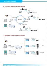
1.4 Typical Application of the Product<br />
E1<br />
Application of point-to-point connection<br />
E1<br />
Application of the star network composed of ERM-<strong>MUX</strong>/PLUS and <strong>ETU02</strong>-<strong>MUX</strong>/<strong>Plus</strong><br />
11
2. Chassis and Interface Modules<br />
Chapter 2. Chassis and Interface Modules<br />
2.1 Description of the Chassis<br />
19" 1U standard cabinet can be adopted and it can be placed on desk or installed in a rack. The power supply can be<br />
220V/110VAC or -48VDC.<br />
2.1.1 Introduction of the Front Panel<br />
The uplink interface module slot is at the left side of the front of the cabinet (as shown in figure 2.1) and the single E1<br />
module or the double E1 module with Sub E1 can be used. See Introduction of Interface Module for the details of the<br />
module.<br />
Figure 2.1<br />
Sketch map of the front panel of <strong>ETU02</strong>-<strong>MUX</strong>/<strong>Plus</strong><br />
The SNMP network management interface at the middle is a RJ45 interface. The locally configured interface console<br />
adopts DB9 interface. See Section 3.4 for the map of the pin-out positions and see Chapter 4 Setup of the Monitoring<br />
Menu for the detailed steps of the device layout and monitoring through the console port. (See the Operation <strong>Manual</strong> of<br />
SNMP Network Management for the detailed operation of SNMP network management)<br />
Description of the indicator lights on the front panel:<br />
Indicator light <strong>Co</strong>lor Description<br />
Power Green The lighting expresses that the power supply is on.<br />
Alarm Red The lighting expresses that there is a failure.<br />
Module1: 1-4 Green The lighting expresses that Route N (N=1-4) of the module is in work.<br />
Module2: 1-4 Green The lighting expresses that Route N (N=1-4) of the module is in work.<br />
Module3: 1-4 Green The lighting expresses that Route N (N=1-4) of the module is in work.<br />
SNMP<br />
Link Yellow The lighting expresses that the Ethernet port has been connected.<br />
Active Green The coruscation expresses that data are being transmitted.<br />
Note:<br />
When G703/64K card is used, the indicator light only expresses the signal state of G703/64K channel. The<br />
lighting expresses that there are signals and the extinguishing of the light expresses that there is no signal.<br />
2.1.2 Introduction of the Back Panel<br />
The power supply socket and switch is at the left side on the back panel of the cabinet. There are three slots of Module<br />
1, Module 2 and Module 3 from left to right where the user can plug all kinds of user modules at will.<br />
Figure 2.2<br />
Sketch map of the back panel of <strong>ETU02</strong>-<strong>MUX</strong>/<strong>Plus</strong><br />
12
The 220VAC power supply is as shown in the following figure.<br />
Chapter 2. Chassis and Interface Modules<br />
Right: AC live conductor<br />
Left: AC sero conductor<br />
Middle: Ground wire of the casing<br />
Figure 2.3<br />
Sketch map of the AC power supply socket<br />
The -48VDC is as shown in the following figure, of which FG is the ground wire of the casing.<br />
0V -48V<br />
FG<br />
Figure 2.4<br />
Sketch map of the DC power supply socket<br />
2.2 Introduction of Interface Modules<br />
2.2.1 Single E1 Uplink Module<br />
The single E1 uplink module provides balanced (RJ45) and unbalanced (BNC) E1 interfaces. The E1 card provides<br />
corresponding E1 status indicator lights, including Signal Loss, Sync Loss and Alarm and supports the multiplexing of<br />
data and voice at the same time.<br />
Description of the indicator lights on the module:<br />
Signal Loss Red, the lighting expresses that the E1 circuit is provided with no signal;<br />
Sync Loss Red, the lighting expresses that the E1 circuit frame is out of synchronous;<br />
Alarm Red, the lighting expresses that the E1 module gives an alarm.<br />
Figure 2.5<br />
Single E1 card<br />
13
2.2.2 Double E1 Uplink Module with Sub E1<br />
Chapter 2. Chassis and Interface Modules<br />
The double E1 uplink module provides Main E1 and Sub E1 interfaces. E1 interface is an unbalanced (BNC) interface.<br />
The E1 card provides the status indicator light of every E1, including Signal Loss, Sync Loss and Alarm. Sub E1 uses<br />
the transmission bandwidth of Main E1 with the rate of N×64K (N=1~31) and supports the multiplexing of the data<br />
and voice service at the same time.<br />
Description of the indicator lights on the module:<br />
Signal Loss Red, the lighting expresses that the E1 circuit is provided with no signal;<br />
Sync Loss Red, the lighting expresses that the E1 circuit frame is out of synchronous;<br />
Alarm Red,the lighting expresses that the E1 module gives an alarm.<br />
Figure 2.6<br />
Double E1 card<br />
2.2.3 N64K-V.35 Module<br />
Every N64K-V.35 module is provided with a data port connector to support 2 high speed data interfaces.<br />
The interface uses the SCSI 68 female connector and makes the switchover with “Y” shape cable. Every module<br />
interface is the DB25 female connector and is the interface standards of V.35, RS530, X21 and RS449 etc. The<br />
interface belongs to DCE.<br />
The selectable rate range of every interface is N×64K (N=1~31).<br />
Figure 2.7<br />
N64K-V.35 card<br />
14
Chapter 2. Chassis and Interface Modules<br />
2.2.4 RS232 Module<br />
Every RS-232 module is provided with a data port connector and supports four RS232 synchronous/asynchronous data<br />
interfaces. The interface uses the SCSI 68 female connector and makes the switchover with a 4-in-1 cable. Every<br />
module interface is the DB25 female connector, the interface belongs to DCE, and it is adequate for synchronous<br />
transmission and asynchronous transmission at the same time. In the normal user application mode, the selectable range<br />
of the interface data rate is ≤38.4K for asynchronous and 19.2K/38.4K/64K/128K for synchronous mode. In the<br />
transparent work mode, every RS232 port can provide independent clock or provide no clock and the selectable range<br />
of the data rate at the interface is ≤38.4K for asynchronous and 9.6K/19.2K for transparent or synchronous mode.<br />
Figure 2.8<br />
RS232 card<br />
2.2.5 ET100 Module<br />
Every ET100 module is provided with 2 RJ45 Ethernet interfaces and supports the connection with two lines of<br />
10/100M Ethernet. Every port on the back panel is provided with the link status indicator lights. The lighting expresses<br />
that the link is on and the extinguishing of the light expresses that the link is off. The Ethernet port supports 802.3X<br />
flow control and is provided with MAC address filtering function. The list of the 256 addresses can be automatically<br />
updated within 5 minutes and transmission bandwidth of WAN can be saved through the check of the MAC addresses<br />
of the data package and the filtration of the data package transmitted to the local. The port is provided with Auto-MDIX<br />
function and the line is provided with self application function.<br />
Figure 2.9<br />
ET100 card<br />
15
Chapter 2. Chassis and Interface Modules<br />
2.2.6 FXS Voice Module<br />
Every FXS voice module is provided with four RJ45 voice interfaces and supports 4 lines of voices. Every module is<br />
provided with four FXS interfaces and can be connected with telephones. Through FXS interfaces, the module can be<br />
connected with the external lines of the telephones at the FXO interfaces of the remote device (in normal mode) and<br />
can be also connected with the hot lines of the telephones at the FXS interfaces of the opposing party (in hot line<br />
mode).<br />
Figure 2.10<br />
FXS card<br />
2.27 FXO Voice Module<br />
Every FXO voice module is provided with four RJ45 voice interfaces and supports 4 lines of voice. Every module is<br />
provided with four FXO interfaces to connect the external lines of PBX (exchange). Through the FXO interfaces, the<br />
module can be connected with the telephones at the FXS interfaces of the remote device.<br />
Figure 2.11<br />
FXO card<br />
16
Chapter 2. Chassis and Interface Modules<br />
2.2.8 E&M Voice Module<br />
Every E&M voice module is provided with four RJ45 voice interfaces and supports 4 lines of voice. Every module is<br />
provided with four E&M interfaces to provide 600 ohms two-line/four-line voice transmission and E&M signaling<br />
interfaces (Type 1–Type 5).<br />
Figure 2.12<br />
E&M card<br />
2.2.9 G703/64K Module<br />
Every G703/64K card is provided with two RJ45 interfaces and supports two G703/64K channels. The interface type of<br />
the module belongs to 64Kbps co-directional interface complying with the coding rules for ITU-T G.703-64K<br />
co-directional interface, the rate of the interface is 64Kbps±100ppm, and the transmission distance through the cable<br />
with the diameter between 0.5mm and 0.7mm is 600m.<br />
Figure 2.13<br />
G703/64K card<br />
17
Chapter 3. Installation<br />
3. Installation<br />
Figure 3.1<br />
Appearance of <strong>ETU02</strong>-<strong>MUX</strong>/<strong>Plus</strong><br />
3.1 Installation of the Machine Frame onto the Chassis or Cabinet<br />
Through the adjustment of the adapter brackets at the sides of the machine frame, the machine frame can be installed<br />
on the 19" chassis or the cabinet. The position of the brackets installed at the sides of the machine frame are shown in<br />
figure 3.2.<br />
Direction of the front panel<br />
Figure 3.2<br />
Installation of the Rack mounting brackets (top view)<br />
3.2 Inserting of Various Cards into <strong>Co</strong>rresponding Slots<br />
Insert the selected E1 card into the E1 slot on the front panel. Insert the selected I/O plug-in cards into the Model 1,<br />
Model 2 and Model 3 slot on the back panel and the types of the IO cards can be combined at will.<br />
3.3 <strong>Co</strong>nnection of the Power Supply<br />
The user can select and use 220VAC or -48VDC power supply. It should be noted that the DC back panel is different<br />
from the AC back panel and see Section 2.1.2 Introduction of the Back Panel.<br />
3.4 <strong>Co</strong>nnection of the Interface at the Monitor Terminal<br />
The DB9 straight-through cable supplied with the device is used to realize the connection between PC and the console<br />
port on the front panel. The signal mode is RS232, the baud rate is 9,600bps, there are 8 data bits and 1 stop bit, and<br />
there is no parity check and flow control.<br />
18
Chapter 3. Installation<br />
3.5 <strong>Co</strong>nnection Interface of E1 Line<br />
The E1 is provided with balanced interface and unbalanced interface respectively introduced through the front panel<br />
(see figure 2.5 and figure 2.6).<br />
3.6 <strong>Co</strong>nnection Interface of the Back Panel of the IO Card<br />
The cable connections at various IO ports are different, but they are all introduced through the back panel. See Annex B<br />
for the list of various cables and see figure 3.3, figure 3.4 and figure 3.5 for the connection of the cross cables at the<br />
data interfaces.<br />
Note: No DTR, DSR, ETC or RC are used when in asynchronous mode<br />
Figure 3.3<br />
Cross-cable for RS-232<br />
Figure 3.4 Cross-cable for V.35<br />
19
Chapter 3. Installation<br />
REM-<strong>MUX</strong><br />
SG<br />
T(A)<br />
R(A)<br />
T(B)<br />
R(B)<br />
C(A)<br />
I(A)<br />
C(B)<br />
I(B)<br />
S(A)<br />
B(A)<br />
S(B)<br />
B(B)<br />
MODEM<br />
SG<br />
T(A)<br />
R(A)<br />
T(B)<br />
R(B)<br />
C(A)<br />
I(A)<br />
C(B)<br />
I(B)<br />
S(A)<br />
B(A)<br />
S(B)<br />
B(B)<br />
Figure 3.5 Cross-cable for X.21<br />
20
Chapter 4. Provisioning<br />
4. Provisioning<br />
This chapter shall introduce how <strong>ETU02</strong>-<strong>MUX</strong>/<strong>Plus</strong> is configured with E1 circuit (monitor terminal).<br />
4.1 Preparation<br />
Before setup, DB9 straight-through serial-port line is used to connect the E1 circuit (monitor terminal) interface of<br />
<strong>ETU02</strong>-<strong>MUX</strong>/<strong>Plus</strong> with the standard terminal or emulation terminal (for example, the hyper terminal card of the PC).<br />
The parameters of the serial port: the baud rate is 9,600bps, there are 8 data bits and 1 stop bit, and there are no parity<br />
checks and flow control.<br />
4.1.1 Startup<br />
The startup menu is as follows: The system card firstly gives the information of all slots after retrial, the prompt of the<br />
first startup is displayed provided that the system is started up for the first time, then the system is initialized, and the<br />
current system parameters in the memory is called out to set up the system provided that the system was set up last time.<br />
The prompt is as follows:<br />
Initializing, please wait …<br />
Start configure …<br />
If the setup is successful, the prompt that the E1 is successfully set up and IO slot is successfully set up (XXX SET OK!<br />
It indicates that the corresponding slot position and card are successfully set up). The interface is as shown in the<br />
following figure:<br />
Current version is 1.05<br />
Self checking….<br />
FPGA TEST OK! //FPGA self-check successful<br />
System Worked for the Independent Clock Mode! //the current work mode of the system<br />
(see the note)<br />
RAM TEST OK! //RAM testing self-check successful<br />
//If FPGA or RAM test fails, the display is as follows:<br />
FPGA TEST ERR!<br />
RAM TEST ERR!<br />
Today is a bright day!<br />
E1 Card is 2*E1 //the type of the E1 card<br />
Slot1 is ET100 //the card type in Slot 1<br />
Slot2 is N64K //the card type in Slot 2<br />
Slot3 is RS232 //the card type in Slot 3<br />
Initializing, please wait...... //prompting the initializing and please wait!<br />
Start configure, //the start of the parameter configuration of the system<br />
E1 SET OK!<br />
//means that E1 is successfully set up.<br />
SLOT1 SET OK! //means that Slot 1 is successfully set up.<br />
SLOT2 SET OK! //means that Slot 2 is successfully set up.<br />
SLOT3 SET OK! //means that Slot 3 is successfully set up.<br />
Press ESC to enter the MENU //the parameter information can be browsed after<br />
pressing ESC and the previous menu can be entered. In order to<br />
meet the different demands of the users, press any key but ESC<br />
in the current menu to skip over the display interface and prompt<br />
the user to input the password of the system.<br />
21
Chapter 4. Provisioning<br />
Note:<br />
The low speed RS 232 card corresponds with two work modes, namely normal work mode and independent external<br />
clock mode. In normal work mode, the prompt of the work mode after startup is as follows:<br />
System Worked for the Normal Mode!<br />
The prompt of the work in independent external clock mode is as follows:<br />
System Worked for the Independent Clock Mode!<br />
4.1.2 Startup Display System and IO Card Setup Parameters and Status Information<br />
The startup menu prompts the pressing of ESC to enter into the menu. In current menu, press ESC to pop up the<br />
configuration parameters and status information of all cards, and then prompt the input of the system password to enter<br />
into the previous menu. In this case, it is displayed that the system clock is the main link recovery clock without<br />
network management, the type, status and work mode of E1 are displayed in turn, then the setup information and the<br />
link synchronizing information of Main E1, the setup information of Sub E1, the link synchronizing information and<br />
the work time slot of Sub E1 are displayed respectively, the type and work status of the IO card at every slot position<br />
are displayed in turn from Slot 1, and the setup information, line status and data activation of every channel are<br />
displayed respectively. The meaning of every character string shall be detailed in the IO card setup and status analysis.<br />
The menu is as follows:<br />
System Parameter: Main E1 Recovery CLK, NO Nmp //displaying the system parameters<br />
(system clock and network management)<br />
E1 Link 2*E1 STATUS: Normal<br />
//the type and status of E1 card<br />
WorkMode: Sub E1<br />
//the work mode of E1 card<br />
***Main E1***<br />
//the setup parameters and link information<br />
of Main E1<br />
Parameter: CCS&Ts0 Pass Disable, CRC4 Disable, NO Loop, HDB3, -12dB, 75 Ohm, 128Bit<br />
Status: Signal Loss, Frame Loss, Remote Frame Loss, AIS Normal<br />
***Sub E1***<br />
//the setup information and link information<br />
of Sub E1<br />
Parameter: CCS&Ts0 Pass Disable, CRC4 Disable, NO Loop, HDB3, -12dB, 75 Ohm, 128Bit<br />
Status: Signal Loss, Frame Loss, Remote Frame Loss, AIS Normal<br />
SubE1 Timeslot: NULL<br />
//the work time slot of Sub E1<br />
SLOT1 ET100 STATUS: Normal<br />
//the type and work status of the IO card<br />
at Slot 1<br />
CH1: NULL, Aneg Enable, Full Duplex, 100M, Flowctrl Disable, MAC Filter Enable, NO<br />
Loop<br />
Link OFF, Data Free<br />
CH2: NULL, Aneg Enable, Full Duplex, 100M, Flowctrl Disable, MAC Filter Enable, NO<br />
Loop<br />
Link OFF, Data Free<br />
SLOT2 N64K/V.35 STATUS: Normal<br />
//the type and work status of the IO card<br />
at Slot 2<br />
CH1: NULL, Internal CLK, NO Loop, DTR OFF, RTS OFF, Data Free<br />
CH2: NULL, Internal CLK, NO Loop, DTR OFF, RTS OFF, Data Free<br />
SLOT3 RS232 STATUS: Normal<br />
//the type and work status of the IO card<br />
at Slot 1<br />
CH1: NULL, Internal CLK, NO Loop, Async19.2K and Below, DTR OFF, RTS OFF, Data Free<br />
CH2: NULL, Internal CLK, NO Loop, Async19.2K and Below, DTR OFF, RTS OFF, Data Free<br />
CH3: NULL, Internal CLK, NO Loop, Async19.2K and Below, DTR OFF, RTS OFF, Data Free<br />
CH4: NULL, Internal CLK, NO Loop, Async19.2K and Below, DTR OFF, RTS OFF, Data Free<br />
Press any key to continue<br />
22
Chapter 4. Provisioning<br />
4.1.3 Input of the Startup Password<br />
The system displays:<br />
Please input your password:<br />
After inputting the password according to the prompt of the system, the user needs to input the password of the system<br />
and then can enter into the previous menu to make the operation of the correction, default and reconfiguration etc. of<br />
the parameters and observe the status and data activation information of the IO card at every slot. The defaulted<br />
original password of the system is 111111. The user can correct the password in the system menu after inputting the<br />
password and entering into the previous menu to make the password comply with own habit. The password must be a<br />
6-bit character combined with any letter (A-Z or a-z) and any number (0-9). If being wrongly input, the password can<br />
be input again. The system displays every input in the form of * and the input can be cancelled by pressing ESC or the<br />
key of “Backspace”.<br />
4.1.4 Display of the Previous Menu<br />
Hello! Welcome you!<br />
Current version is 1.05<br />
<br />
1. E1 Link <strong>Co</strong>nfigure //E1 link parameters browsing/correction menu<br />
2. IO Link <strong>Co</strong>nfigure //IO slot link parameters browsing/correction menu<br />
3. Display Parameter //displaying system setup parameters and status menu<br />
4. Save Parameter //saving and setup device parameters menu<br />
5. Set Default //default device initial value menu<br />
6. Set System //device system parameters browsing/correction menu<br />
0. Exit //exit from the menu<br />
Please input your choice:<br />
Print the welcome words and current firmware version number firstly and then print the previous menu that includes<br />
following 8 sub-menus:<br />
E1 link parameters browsing/correction menu: Include the work mode selection of Main E1 and Sub E1 on E1, the<br />
selection of the work setup parameters of Main E1 and Sub E1 (framing mode, line impedance, interface level, line<br />
coding, and the jittering attenuation FIFO length of the line etc.), and the selection of the work time slot of Sub E1.<br />
IO slot link parameters browsing/correction menu: Search all existing IO cards and then select the time slot, work<br />
mode and the gain and attenuation of every channel according to the type of the card. According to different types of<br />
the cards, the options and ranges are also different (see the setup of every IO card for the details).<br />
Displaying system setup parameters and status menu: The displayed information is consistent with the information<br />
displayed after startup, including the setup information, status information and data activation information of E1 link<br />
and IO cards. After the displaying is completed, the previous menu is backed to.<br />
Saving and setup device parameters menu: Save E1 link configuration, IO slot link configuration, system clock<br />
parameters setup and the BERT configuration parameters of E1 into the memory of the system. All data can be saved<br />
when the power is down. The saved parameters exclude password and the date and time of the system that are saved<br />
immediately after the correction becomes effective.<br />
Default device initial value menu: Resume the system parameters back to the default. The default range excludes the<br />
work mode of E1 (single E1 mode or Sub E1 mode), NMP mode and SNMP setup parameters, device address, network<br />
management time slot and the password, date and time of the system. Other setup parameters relating to E1, BERT<br />
parameters of E1 and the parameters of the IO cards are all resumed back to the default. The default information is<br />
detailed in the independent setup of every card.<br />
In the system setup menu, the current system firmware version can be viewed, the system clock can be set, NMP mode<br />
and correlative parameters can be set, system password can be changed, and the date and time of the system can be<br />
configured and displayed.<br />
Exit from the menu: Select the exit from the previous menu and enter into the monitoring state.<br />
Key in any key from 1 to 6 and press the key Enter to enter into corresponding sub-menus.<br />
Key in 0 and press the key Enter or press the key ESC to back to the monitoring state. It is prompted whether the menu<br />
is exited.<br />
23
Chapter 4. Provisioning<br />
4.2 Setup of E1 Link<br />
In the previous menu, key in 1 and press the key Enter to enter into the setup of E1 link. The menu is displayed as<br />
follows:<br />
<br />
1. Work MODE //E1 card work mode setup menu<br />
2. Main Link //Main E1 link parameters setup<br />
3. Sub Link //Sub E1 link parameters setup<br />
0. Exit //exit from the menu<br />
Please input your choice:<br />
If the single E1 or double-E1 card is in single E1 work mode, the screen displays the sub-menu Sub E1 link parameters<br />
setup. If double-E1 is in sub E1 mode, the above menu is displayed.<br />
The setup content of the sub-menu is as follows:<br />
Selection of E1 work mode: The single E1 card is provided with only one work mode, namely single E1 work mode.<br />
The double-E1 card is provided with the two selections of single E1 work mode and Sub E1 work mode. The work<br />
mode selected at present is expressed with the symbol * before.<br />
Selection of Main E1 link setup: Include the browsing/correction sub-menu of Main E1 framing mode, line impedance,<br />
interface level, line coding, and jittering attenuation FIFO length of the line etc.<br />
Selection of Sub E1 link: Include the browsing/correction sub-menu of Sub E1 framing mode, line impedance, interface<br />
level, line coding, and the jittering attenuation FIFO length of the line etc.<br />
Key in any key from 1 to 3 and press the key Enter to enter into corresponding sub-menus.<br />
Key in 0 and press the key Enter or ESC to back to the previous menu.<br />
4.2.1 Selection of the Operation Mode of E1<br />
Key in 1 in E1 link setup menu and press the key Enter to enter into the selection of E1 work mode and the following<br />
menu pops out:<br />
<br />
1. Single E1 Mode //single E1 work mode<br />
*2. Sub E1 Mode //Sub E1 work mode<br />
0. Exit //exit<br />
Please input your choice:<br />
The current E1 work mode can be browsed and the work mode effectively selected at present is expressed with the<br />
symbol of * before.<br />
Key in the effective number (1 or 2), and then press the 'Enter' key to redisplay the menu. The position of the symbol *<br />
changes, along with the change of the setup values. <strong>Co</strong>nfirm the changed parameters and back to previous menu at the<br />
same time.<br />
Key in 0 and press the key Enter or ESC to back to the previous menu (no parameter changed).<br />
Pointer: If it is a single E1 card, there is only single E1 mode option.<br />
24
Chapter 4. Provisioning<br />
4.2.2 Browsing/Modification of the Setup Parameters of Main E1<br />
Key in 2 in E1 link setup menu and press the key Enter to enter into the browsing/correction of Main E1 setup<br />
parameters and the following menu pops out:<br />
<br />
1. Frame/TS0 Pass //Main E1 framing mode browsing/correction menu<br />
2. CRC-4 //Main E1 frame CRC4 checking browsing/correction menu<br />
3. LoopBack //Main E1 loop mode browsing/correction menu<br />
4. Impendance //Main E1 line impedance mode browsing/correction menu<br />
5. Line <strong>Co</strong>de //Main E1 line coding mode browsing/correction menu<br />
6. RXZ //Main E1 receive equalizer gain level browsing/correction menu<br />
7. Jitter //Main E1 jitter attenuation buffer area depth<br />
browsing/correction menu<br />
0. Exit //exit from the menu<br />
Please input your choice:<br />
The setup content of the sub-menu is as follows:<br />
Main E1 framing mode browsing/correction menu: The framing modes that can be selected include CCS framing mode,<br />
CAS framing mode, CCS framing mode and 0 time slot unvarnished transmission work, CAS framing mode and 0 time<br />
slot unvarnished transmission work.. (Note: no non-framing work mode for <strong>ETU02</strong>-<strong>MUX</strong>/<strong>Plus</strong> E1 link)<br />
Main E1 frame CRC4 checking browsing/correction menu: CRC4 checking ban or allowance can be selected.<br />
Main E1 loop mode browsing/correction menu: The options of no loop, E1 local loop and to-E1/to-opposite terminal<br />
loop can be selected to facilitate the diagnosis testing, among which the “no loop” is used in the normal work mode.<br />
Main E1 line impedance mode browsing/correction menu: Two kinds of line impedance matching modes can be<br />
selected for the application in 75Ω unbalanced coaxial cable and 120Ω balanced twisted pair line respectively.<br />
Main E1 line coding mode browsing/correction menu: Two kinds of line coding modes can be selected, namely HDB3<br />
coding and AMI and coding.<br />
Main E1 receive equalizer gain level browsing/correction menu: Two kinds of line receive equalizer gain levels,<br />
namely -12dB and -43dB, can be selected for short line and long line application.<br />
Main E1 jitter attenuation buffer area depth browsing/correction menu: Two kinds of jitter attenuation buffer area<br />
depths, namely 128bits and 32bits, can be selected. The former is used for most occasions and the later is used for the<br />
occasions that are extremely sensitive to time delay.<br />
Key in any key from 1 to 7 and press the key Enter to enter into corresponding sub-menus.<br />
Key in 0 and press the key Enter or press ESC to back to the previous menu.<br />
4.2.2.1 Browsing/Modification of the Framing Mode of Main E1<br />
Key in 1 in Main E1 link setup menu and press the key Enter to enter into the selection of the framing modes of Main<br />
E1 and the following menu pops out:<br />
<br />
*1. CCS //CCS framing mode (PCM31)<br />
2. CAS //CAS framing mode (PCM30)<br />
3. CCS+TS0 Pass //CCS framing mode and 0 time slot transparent transmission<br />
4. CAS+TS0 Pass //CAS framing mode and 0 time slot transparent transmission<br />
0. Exit //exit<br />
Please input your choice:<br />
The current framing modes of Main E1 can be browsed and the framing mode effectively selected at present is<br />
provided with the symbol * before.<br />
Key in the effectively selected number (1-4) and then press the key Enter to redisplay the menu, but the position of the<br />
symbol * changes along with the change of the setup values. <strong>Co</strong>nfirm the changed parameters and back to the previous<br />
menu at the same time.<br />
Key in 0 and press the key Enter or ESC to back to the previous menu (no parameter changed).<br />
25
Chapter 4. Provisioning<br />
4.2.2.2 Browsing/Modification of the CRC4 Verification Mode of Main E1<br />
Key in 2 in the Main E1 link setup menu and press the key Enter to enter into the selection of Main E1 CRC4 checking<br />
mode and the following menu pops out:<br />
<br />
*1. OFF //CRC4 checking ban<br />
2. ON //CRC4 checking permitted<br />
0. Exit //exit<br />
Please input your choice:<br />
CRC4 checking mode if the current Main 4 can be browsed and the CRC4 checking mode effectively selected at<br />
present is provided with the symbol * before.<br />
Key in the effective number (1 or 2) and then press the key Enter to redisplay the menu, but the position of the symbol<br />
* changes along with the change of the setup values. <strong>Co</strong>nfirm the changed parameters and back to previous menu at the<br />
same time.<br />
Key in 0 and press the key Enter or ESC to back to the previous menu (no parameter changed).<br />
4.2.2.3 Browsing/Modification of the Loop Mode of Main E1<br />
Key in 3 in Main E1 link setup menu and press the key Enter to enter into the selection of Main E1 loops and the<br />
following menu pops out:<br />
<br />
*1. NO LOOP //No loop mode<br />
2. Local LOOP //local loop mote<br />
3. TO Remote LOOP //to remote loop mode<br />
0. Exit //exit<br />
Please input your choice:<br />
The current loop mode of Main E1 can be browsed and the loop mode effectively selected at present is provided with<br />
the symbol * before.<br />
Key in the effectively selected number (1-3) and then press the key Enter to redisplay the menu, but the position of the<br />
symbol * changes along with the change of the setup values. <strong>Co</strong>nfirm the changed parameters and back to previous<br />
menu at the same time.<br />
Key in 0 and press the key Enter or ESC to back to the previous menu (no parameter changed).<br />
4.2.2.4 Browsing/Modification of the Line Impedance of Main E1<br />
Key in 4 in the Main E1 link setup menu and press the key Enter to enter into the selection of Main E1 line impedance<br />
mode and the following menu pops out:<br />
<br />
*1. 75 Ohm //75 ohms BNC unbalanced interface mode<br />
2. 120 Ohm //120 ohms balanced twisted pair line interface mode<br />
0. Exit //exit<br />
Please input your choice:<br />
The current line impedance mode of Main E1 can be browsed and the line impedance mode effectively selected at<br />
present is provided with the symbol * before.<br />
Key in the effective number (1 or 2) and then press the key Enter to redisplay the menu, but the position of the symbol<br />
* changes along with the change of the setup values. <strong>Co</strong>nfirm the changed parameters and back to previous menu at the<br />
same time.<br />
Key in 0 and press the key Enter or ESC to back to the previous menu (no parameter changed).<br />
26
Chapter 4. Provisioning<br />
4.2.2.6 Browsing/Modification of the Line <strong>Co</strong>ding Mode of Main E1<br />
Key in 5 in Main E1 link setup menu and press the key Enter to enter into the selection of Main E1 line coding and the<br />
following menu pops out:<br />
<br />
1. AMI //AMI coding mode<br />
*2. HDB3 //HDB3 coding mode<br />
0. Exit //exit<br />
Please input your choice:<br />
The current line coding mode of Main E1 can be browsed and the line coding mode effectively selected at present is<br />
provided with the symbol * before.<br />
Key in the effective number (1 or 2) and then press the key Enter to redisplay the menu, but the position of the symbol<br />
* changes along with the change of the setup values. <strong>Co</strong>nfirm the changed parameters and back to previous menu at the<br />
same time.<br />
Key in 0 and press the key Enter or ESC to back to the previous menu (no parameter changed).<br />
4.2.2.6 Browsing/Modification of the Receive Equalizer Gain Level of Main E1<br />
Key in 6 in Main E1 link setup menu and press the key Enter to enter into the selection of Main E1 receive equalizer<br />
gain level and the following menu pops out:<br />
<br />
*1. -12dB //receive equalizer gain level: -12dB<br />
2. -43dB //receive equalizer gain level: -43dB<br />
0. Exit //exit<br />
Please input your choice:<br />
The current receive equalizer gain level of Main E1 can be browsed and the receive equalizer gain level of Main E1<br />
effectively selected at present is provided with the symbol * before.<br />
Key in the effective number (1 or 2) and then press the key Enter to redisplay the menu, but the position of the symbol<br />
* changes along with the change of the setup values. <strong>Co</strong>nfirm the changed parameters and back to previous menu at the<br />
same time.<br />
Key in 0 and press the key Enter or ESC to back to the previous menu (no parameter changed).<br />
4.2.2.7 Browsing/Modification of the Depth of the Jitter Attenuation Buffer Area of Main E1<br />
Key in 7 in Main E1 link setup menu and press the key Enter to enter into the selection of the jitter attenuation buffer<br />
area depth of Main E1 and the following menu pops out:<br />
<br />
1. 32Bit //jitter attenuation buffer area depth: 32bits<br />
*2. 128Bit //jitter attenuation buffer area depth: 32bits<br />
0. Exit //exit<br />
Please input your choice:<br />
The current jitter attenuation buffer area depth of Main E1 can be browsed and the jitter attenuation buffer area depth of<br />
Main E1 effectively selected at present is provided with the symbol * before.<br />
Key in the effective number (1 or 2) and then press the key Enter to redisplay the menu, but the position of the symbol<br />
* changes along with the change of the setup values. <strong>Co</strong>nfirm the changed parameters and back to previous menu at the<br />
same time.<br />
Key in 0 and press the key Enter or ESC to back to the previous menu (no parameter changed).<br />
27
Chapter 4. Provisioning<br />
4.2.3 Browsing/Modification of Sub E1 Setup Parameters<br />
Key in 3 in E1 link setup menu and press the key Enter to enter into the browsing/correction of Sub E1 setup<br />
parameters and the following menu pops out:<br />
<br />
1. Frame/TS0 Pass //Sub E1 framing mode browsing/correction menu<br />
2. CRC-4 //Sub E1 frame CRC4 checking browsing/correction menu<br />
3. LoopBack //Sub E1 loop mode browsing/correction menu<br />
4. Impedance //Sub E1 line impedance mode browsing/correction menu<br />
5. Line <strong>Co</strong>de //Sub E1 line coding mode browsing/correction menu<br />
6. RXZ //Sub E1 receive equalizer gain level browsing/correction menu<br />
7. Jitter //Sub E1 jitter attenuation buffer menu<br />
8. Sub E1 Timeslot //Sub E1 time slot selection and clearance menu<br />
0. Exit //exit<br />
Please input your choice:<br />
The setup content of the sub-menu is as follows:<br />
Sub E1 framing mode browsing/correction: Four framing modes can be selected, namely CCS framing mode, CAS<br />
framing mode, CCS framing mode and 0 time slot unvarnished transmission work, CAS framing mode and 0 time slot<br />
transparent transmission work. (Note: no unframed work mode for <strong>ETU02</strong>-<strong>MUX</strong>/<strong>Plus</strong> E1)<br />
Sub E1 frame CRC4 checking browsing/correction: CRC4 checking forbidden or allowance can be selected.<br />
Sub E1 loop mode browsing/correction: The options of no loop, E1 local loop and to-E1/to-opposite terminal loop can<br />
be selected to facilitate the diagnosis testing, among which the “no loop” is used in the normal work mode.<br />
Sub E1 line impedance mode browsing/correction: Two kinds of line impedance matching modes can be selected for<br />
the application in 75Ω unbalanced coaxial cable and 120Ω balanced twisted pair line respectively.<br />
Sub E1 line coding mode browsing/correction: Two kinds of line coding modes can be selected, namely HDB3 coding<br />
and AMI and coding.<br />
Sub E1 receive equalizer gain level browsing/correction: Two kinds of line receive equalizer gain levels, namely<br />
-12dB and -43dB, can be selected for short line and long line application.<br />
Sub E1 jitter attenuation buffer area depth browsing/correction: Two kinds of jitter attenuation buffer area depths,<br />
namely 128bits and 32bits, can be selected. The former is used for most occasions and the later is used for the<br />
occasions that are extremely sensitive to time delay.<br />
Sub E1 time slot selection and clearance: The multiplexing of Sub E1 is consistent with that of other IO cards, any idle<br />
time slot can be selected and used at will, and the maximum rate of the multiplexing of Sub E1 is 1,984K (31 time<br />
slots). In this sub-menu, the time slot of Sub E1 can be cleared and established (see the following text for the detailed<br />
operation).<br />
Key in any key from 1 to 8 and press the key Enter to enter into corresponding sub-menus.<br />
Key in 0 and press the key Enter or press ESC to back to the previous menu.<br />
The selection of Sub-menu 1 to 7 is totally consistent with the selection of Main E1 setup parameters and the setup<br />
mode and option are totally identical, so the unnecessary details would not be described here. See the section of Main<br />
E1 menu for the meanings of all options and only the time slot setup and clearance sub-menu of Sub E1 are introduced<br />
here.<br />
4.2.3.1 Browsing/Modification of the Time Slot Setup of Sub E1<br />
Key in 8 in the Sub E1 link setup menu and press the key Enter to enter into Sub E1 time slot setup/correction and the<br />
following menu pops out:<br />
<br />
Current Free Timeslot: 01-31 //the current free time slots are 1-31<br />
Current SubE1 Timeslot: NULL //the current Sub E1 work time slot is blank<br />
Input SubE1 Timeslot: //input format example: 1-10, 11, 15-20<br />
Please input timeslot:<br />
//the working time slot or group can be input<br />
28
Chapter 4. Provisioning<br />
Firstly prompt the current idle time slots and make the list, and then prompt the current Sub E1 time slot and give the<br />
input format example for reference. Pay attention to the format that has been input. For example, in the interface in<br />
above figure, input 2-15 and press the key Enter, display after successful input that the current Sub E1 time slot is<br />
02-15, and back to the previous menu.<br />
Pointer: When being input, the time slots are spaced with the symbol “,” and the time slots are put in order according<br />
to the serial numbers from small to large. The input should be free of the characters outside numbers, “,” and “-” and<br />
the input should be ended with the pressing of the key Enter. If the input time slots have been occupied or the input<br />
format is wrong, the input should be repeated. After inputting ESC or inputting Enter in the position where the input of<br />
the time slot is prompted, back to the previous menu directly.<br />
INPUT ERR INPUT AGAIN!<br />
THE USED TIMESLOT: 01<br />
//the input is wrong or the format is wrong.<br />
//the input time slot is already occupied.<br />
4.3 Setup of the I/O Card<br />
Key in 2 in the previous menu and press the key Enter to enter into IO slot link parameters browsing/correction menu<br />
and check IO cards to display the numbers of the slots occupied by current IO cards:<br />
IO LINK <strong>Co</strong>nfiguration<br />
Search....<br />
Board NO.: 1, 2, 3 //the slot numbers of current IO cards or NULL when there is<br />
no IO card in the slot<br />
INPUT Board NO:<br />
//Slot numbers of the selected IO cards and press the key Enter to enter into<br />
corresponding IO cards setup. If there is no IO card at the input slot, the displaying<br />
is as follows:<br />
This NO. isn't exist!<br />
Board NO.:1, 2, 3<br />
INPUT Board NO:<br />
//Input of the IO slot number and key in ESC or Enter in the current interface to back to the previous menu.<br />
The following text shall describe the setup menus of all IO cards in detail.<br />
4.3.1 Setup of N64K/V.35 Card<br />
Key in the number of the N64K/V.35 located slot at the IO card setup input entry point and press the key Enter to check<br />
and display the current configuration information and the link status information of N64K/V35 card. For the<br />
description of the meanings of the specific information, see the following text about the description of the parameters<br />
setup and data link status information of N64K/V.35 card.<br />
SLOT1 N64K/V.35 STATUS: Normal<br />
Slot number IO card type IO card status<br />
CH1: NULL, Internal CLK, NO Loop, DTR OFF, RTS OFF, Data Free<br />
Time slot clock mode loop mode DTR signal RTS signal data activation<br />
signal<br />
CH2: NULL, Internal CLK, NO Loop, DTR OFF, RTS OFF, Data Free<br />
29
Chapter 4. Provisioning<br />
4.3.1.1 Display of N64K/V35 Menu<br />
<br />
1. CH1 //CH1 setup menu<br />
2. CH2 //CH2 setup menu<br />
0. Exit //exit<br />
Please input your choice:<br />
Key in o and press the key Enter or key in ESC and press the key Enter to back to the selection of IO card interface.<br />
Key in 1-2 and press the key Enter to enter into N64K/V.35 channel setup (the setup of Channel 1-2 identical)<br />
Key in other keys and press the key Enter to back to the selection of IO card interface.<br />
4.3.1.2 Display of N64K/V35 Channel Menu<br />
In N64K/V35 setup menu status, select the setup channel (for example, channel 1) to set up the channel and the menu<br />
displays as follows:<br />
<br />
1. Timeslot //setting up the multiplexing time slot number<br />
2. Clock //setting up the channel clock mode<br />
3. Loop //setting up the channel loop mode<br />
0. Exit //exit<br />
Please input your choice:<br />
Key in 0 and press the key Enter or key in ESC to back to the previous menu<br />
Key in 1-3 and press the key Enter to enter into corresponding setup options<br />
Key in other keys and press the key Enter to back to the previous menu<br />
4.3.1.3 Setup of the Multiplexing Time Slot Number<br />
Enter into the setup of the multiplexing time slot number selection menu where the E1 time slot multiplexed by this<br />
channel can be selected and the following menu pops out:<br />
<br />
Current Free Timeslot: 01-31<br />
Current Timeslot: NULL<br />
Please Input Timeslot:<br />
One or more than one idle time slots (periods) can be input according to following input format:<br />
The list of the time slots can include one or more than one continuous time slots and the format of the later is starting<br />
time slot – ending time slot;<br />
After inputting the list of the idle time slots, press the key Enter to correct the confirmation and back to the previous<br />
menu.<br />
If the input time slot has been occupied, the prompt is as follows:<br />
THE USED TIMESLOT: XX //displays the number of the occupied slots<br />
INPUT ERR, INPUT AGAIN! //the input is wrong and requires the repetition of the<br />
input<br />
If the format of the input time slot is wrong, only prompt the input error and back to the starting interface of the time<br />
slot input and require the repetition of the input of the time slot.<br />
If there is no time slot input, press the key Enter or ESC to back to the previous channel setup menu.<br />
Pointer: For N64K/V.35, every channel can use Time Slot 1-31 with the rate between 64K and 1984K.<br />
30
Chapter 4. Provisioning<br />
4.3.1.4 Setup of the Clock Mode<br />
Enter into the setup of the clock mode selection menu where the clock modes of this channel can be selected and the<br />
following menu pops out:<br />
<br />
*1. Internal CLK //the channel is internal clock mode.<br />
2. External CLK //the channel is external clock mode.<br />
0. Exit //exit<br />
Please input your choice:<br />
The current channel clock mode of N64K/V.35 can be browsed and the clock mode effectively selected at present is<br />
provided with the symbol * before.<br />
Key in the effective number (1 or 2) and then press the key Enter to redisplay the menu, but the position of the symbol<br />
* changes along with the change of the setup values. <strong>Co</strong>nfirm the changed parameters and back to previous menu at the<br />
same time.<br />
Key in 0 and press the key Enter or ESC to back to the previous menu (no parameter changed).<br />
Pointer: The setting of the external clock is provided with meanings only when the interface is used as DTE. Now,<br />
113-clock is used as the transmission clock to make the externally connected device use this device as the clock source.<br />
If the external mode is selected, the device uses 115-receving clock to sample the receive data 104.<br />
4.3.1.5 Setup of the Loop Mode<br />
Enter into the setup of the loop mode selection menu where the data loop mode of this channel can be selected and the<br />
following menu pops out:<br />
<br />
*1. NO Loop<br />
2. Loop<br />
0. Exit<br />
Please input your choice:<br />
The current channel loop mode of N64K/V.35 can be browsed and the clock mode option effectively selected at present<br />
is provided with the symbol * before.<br />
Key in the effective number (1 or 2) and then press the key Enter to redisplay the menu, but the position of the symbol<br />
* changes along with the change of the setup values. <strong>Co</strong>nfirm the changed parameters and back to previous menu at the<br />
same time.<br />
Key in 0 and press the key Enter or ESC to back to the previous menu (no parameter changed).<br />
4.3.2 Setup of RS232 Card<br />
Key in the number of the RS232 located slot at the IO card setup input entry point and press the key Enter to check and<br />
display the current configuration information and the link status information of RS232 card. For the description of the<br />
meanings of the specific information, see the following text about the description of the parameters setup and data link<br />
status information of RS232 card.<br />
SLOT3 RS232 STATUS: Normal<br />
Slot number IO card type IO card status<br />
RS232 Card can work for the Independent Clock Mode<br />
Description of the work mode of the current system:<br />
CH1: NULL, Internal CLK, NO Loop, Async19.2K and Below, DTR OFF, RTS OFF, Data Free<br />
Time slot clock mode loop mode work mode DTR signal RTS signal data<br />
activation signal<br />
CH2:NULL,Internal CLK,NO Loop,Async19.2K and Below,DTR OFF,RTS OFF,Data Free<br />
CH3:NULL,Internal CLK,NO Loop,Async19.2K and Below,DTR OFF,RTS OFF,Data Free<br />
CH4:NULL,Internal CLK,NO Loop,Async19.2K and Below,DTR OFF,RTS OFF,Data Free<br />
31
Chapter 4. Provisioning<br />
4.3.2.1 Display of RS232 Menu<br />
<br />
1. CH1 //CH1 setup menu<br />
2. CH2 //CH1 setup menu<br />
3. CH3 //CH1 setup menu<br />
4. CH4 //CH1 setup menu<br />
0. Exit //exit<br />
Please input your choice:<br />
Key in 0 and press the key Enter or ESC to back to the IO card selection interface.<br />
Key in 1-4 and press the key Enter to enter into RS232 channel setup (the setup of Channel 1-4 identical)<br />
Key in other keys and press the key Enter to back to the selection of IO card interface.<br />
4.3.2.2 Display of RS232 Channel Menu<br />
In RS232 setup menu state, select the setup channel (for example, Channel 1) to set the channel and the menu display:<br />
<br />
1. Timeslot<br />
2. Workmode<br />
3. Loop<br />
4. Clock<br />
0. Exit<br />
Please input your choice:<br />
Key in 0 and press the key Enter or ESC to back to the previous menu.<br />
Key in 1-4 and press the key Enter to enter into corresponding setup options<br />
Key in other keys and press the key Enter to back to the previous menu.<br />
4.3.2.3 Setup of the Multiplex Time Slot Number<br />
Enter into the setup of multiplexing time slot number selection menu where the multiplexed E1 time slot number can be<br />
selected and the following menu pops out:<br />
<br />
Current Free Timeslot: 01-31<br />
Current Timeslot: NULL<br />
Please Input Timeslot:<br />
One or two idle time slots (periods) can be input and the input format is as follows:<br />
One or two idle time slots can be input and the input<br />
The list of the time slots can include one or more than one continuous time slots and the format of the later is starting<br />
time slot – ending time slot;<br />
After inputting the list of the idle time slots, press the key Enter to correct the confirmation and back to the previous<br />
menu.<br />
If the input time slot has been occupied, the prompt is as follows:<br />
THE USED TIMESLOT: XX //displays the number of the occupied slot<br />
INPUT ERR, INPUT AGAIN! //the input is wrong and requires the repetition of the input<br />
If the format of the input time slot is wrong, only prompt the input error and back to the starting interface of the time<br />
slot input and require the repetition of the input of the time slot. If there is no time slot number to be input, press the<br />
key Enter or ESC to back to the setup menu of the previous channel.<br />
32
Chapter 4. Provisioning<br />
4.3.2.4 Setup of the Channel Operation Mode<br />
Enter into the setup of channel work mode selection menu and the work mode of this channel can be selected. The<br />
following menu pops out. According to the difference of the work modes of the system, the channel work mode of<br />
RS232 card is provided with corresponding difference.<br />
4.3.2.4.1 Description of the Channel Operation Mode of RS232 in Normal Mode<br />
When the time slots are not distributed or a time slot is selected, the work mode selection menu is as follows:<br />
<br />
*1. Async19.2K and Below //the rate is asynchronous 19.2K or below.<br />
2. Sync 19.2K //the rate is synchronous 19.2K.<br />
3. Sync 64K //the rate is synchronous 64K<br />
0. Exit //exit<br />
Please input your choice:<br />
When two time slots are selected, the menu changes into the following format:<br />
<br />
*1. Async38.4K and Below //the rate is asynchronous 38.4K or below.<br />
2. Sync 38.4K //the rate is synchronous 38.4K.<br />
3. Sync 128K // the rate is synchronous 128K.<br />
0. Exit<br />
Please input your choice:<br />
The current RS232 channel work mode can be browsed and t he work mode option effectively selected at present is<br />
provided with the symbol * before.<br />
Key in the effectively selected number (1-3) and then press the key Enter to redisplay the menu, but the position of the<br />
symbol * changes along with the change of the setup values. <strong>Co</strong>nfirm the changed parameters and back to previous<br />
menu at the same time.<br />
Key in 0 and press the key Enter or ESC to back to the previous menu (no parameter changed).<br />
4.3.2.4.2 Description of the Channel Operation Mode of RS232 in Normal Mode<br />
When the time slots are not distributed or a time slot is selected, the work mode selection menu is as follows:<br />
<br />
*1. Async19.2K and Below //the rate is asynchronous 19.2K or below.<br />
2. Sync 9.6K (Independent Clock Mode) //the rate is synchronous 9.6K -<br />
independent external clock mode.<br />
3. Sync 64K //the rate is synchronous 64K.<br />
0. Exit //exit<br />
Please input your choice:<br />
Note: Option 1 is that RS232 port works in the independent external clock mode.<br />
When two time slots are selected, the menu changes as follows:<br />
<br />
*1. Async38.4K and Below //the rate is asynchronous38.4K and below.<br />
2. Sync 19.2K (Independent Clock Mode) //the rate is synchronous 19.2K –<br />
independent external clock mode.<br />
3. Sync 128K // the rate is synchronous 128K.<br />
0. Exit<br />
Please input your choice:<br />
33
Chapter 4. Provisioning<br />
The current RS232 channel work mode can be browsed and the work mode option effectively selected at present is<br />
provided with the symbol *.<br />
Key in the effectively selected number (1-3) and then press the key Enter to redisplay the menu, but the position of the<br />
symbol * changes along with the change of the setup values. <strong>Co</strong>nfirm the changed parameters and back to previous<br />
menu at the same time.<br />
Key in 0 and press the key Enter or ESC to back to the previous menu (no parameter changed).<br />
Pointer: For RS232, every channel is provided with 1-2 time slots and the corresponding work modes are 8.<br />
When one time slot is selected, the following four work modes can be selected: asynchronous 19.2K and below,<br />
synchronous 19.2K, synchronous 64K and synchronous 9.6K in the independent external clock mode.<br />
When two time slots are selected, the following work modes can be selected: asynchronous 38.4K and below,<br />
synchronous 38.4K, synchronous 128K, and the synchronous 19.2K in the independent external clock mode.<br />
4.3.2.5 Setup of the Loop Mode<br />
Enter into the setup of loop mode selection mode where the data loop mode of this channel can be selected and the<br />
following menu pops out:<br />
<br />
*1. NO Loop //no loop mode<br />
2. Loop //data loop mode<br />
0. Exit //exit<br />
Please input your choice:<br />
The current channel loop mode of RS232 can be browsed and the loop mode effectively selected at present is provided<br />
with the symbol * before.<br />
Key in the effective number (1 or 2) and then press the key Enter to redisplay the menu, but the position of the symbol<br />
* changes along with the change of the setup values. <strong>Co</strong>nfirm the changed parameters and back to previous menu at the<br />
same time.<br />
Key in 0 and press the key Enter or ESC to back to the previous menu (no parameter changed).<br />
4.3.2.6 Setup of the Clock Mode<br />
Enter into the setup of the clock mode selection menu where the clock mode of this channel can be selected and the<br />
following menu pops out:<br />
<br />
*1. Internal CLK //the clock inside the channel<br />
2. External CLK //the clock outside the channel<br />
0. Exit //exit<br />
Please input your choice:<br />
The current clock mode of the channel of RS232 can be browsed and the clock mode effectively selected at present is<br />
provided with the symbol *.<br />
Key in the effective number (1 or 2) and then press the key Enter to redisplay the menu, but the position of the symbol<br />
* changes along with the change of the setup values. <strong>Co</strong>nfirm the changed parameters and back to previous menu at the<br />
same time.<br />
Key in 0 and press the key Enter or ESC to back to the previous menu (no parameter changed).<br />
Pointer: When the work mode is asynchronous, the setup of the channel clock is provided without significance. Only<br />
when the interface serves as DTE, the setup of external clock is significant. When being transmitted as DTE, 113-clock<br />
is used to make the externally connected device use this device as the clock source. If the external mode is selected, the<br />
device uses 115-receving clock to sample the receive data 104.<br />
34
Chapter 4. Provisioning<br />
4.3.3 Setup of ET100 Card<br />
In the IO card setup input entry point, key in the number of ET100 card located slot and press the key Enter to check<br />
and display the current setup information and link status information of ET100 card. For the description of specific<br />
information, see the description of the following text relating to ET100 card parameters setup and data link status<br />
information:<br />
SLOT2 ET100 STATUS: Normal<br />
Slot number IO card type IO card status<br />
CH1: NULL, Aneg Enable, Full Duplex, 100M, Flowctrl Disable, MAC Filter Enable, NO<br />
Loop<br />
Time slot adaptive mode duplex mode rate flow control mode address filtering<br />
allowance loop mode<br />
Link OFF, Data Free<br />
Link status data activation status<br />
CH2:NULL,Aneg Enable,Full Duplex,100M,Flowctrl Disable,MAC Filter Enable,NO Loop<br />
,Link OFF,Data Free<br />
4.3.3.1 Display of ET100 Menu<br />
<br />
3. CH1 //CH1 setup menu<br />
4. CH2 //CH2 setup menu<br />
0. Exit //exit<br />
Please input your choice:<br />
Key in 0 and press the key Enter or ESC to back to the selection of IO card interface<br />
Key in 1-2 and press the key Enter to enter into ET100 channel setup (the setup of Channel 1-2 identical)<br />
Key in other keys and press the key Enter to back the IO card selection interface.<br />
4.3.3.2 Display of ET100 Channel Menu<br />
In ET100 setup menu status, select the set up channel (for example, Channel 1) to make channel setup and the menu<br />
displays as follows:<br />
<br />
1. Timeslot //setting the multiplexed time slot number<br />
2. Auto-Negotiation //setting LAN port adaptive mode menu<br />
3. <strong>Co</strong>mmunication Mode //setting the communication duplex mode menu<br />
4. Speed //setting LAN port rate menu<br />
5. Flow <strong>Co</strong>ntrol //setting flow control mode menu<br />
6. MAC Filtering //setting the MAC address filtering allowance menu<br />
7. Local Loop //setting channel loop mode menu<br />
0. Exit //exit<br />
Please input your choice:<br />
Key in 0 and press the key Enter or ESC to back the previous menu<br />
Key in 1-7 and press the key Enter to enter into corresponding setup option<br />
Key in other keys and press the key Enter to back to the previous menu<br />
35
Chapter 4. Provisioning<br />
4.3.3.3 Setup of the Multiplex Time Slot Number<br />
The time slot setup of ET100 is totally identical to that of N64K/V.35 and every channel can be provided with the setup<br />
of 1-31 time slots. The setup method and interface are both totally identical, so the unnecessary details are omitted here.<br />
Pointer: For ET100, every channel can use 1-31 time slots and the rates corresponding to WAN are from 64K to<br />
1,984K.<br />
4.3.3.4 Setup of the Adaptive Mode of LAN Interface<br />
Enter into the setup of LAN port adaptive mode selection menu and the LAN port adaptive mode of this channel can be<br />
selected and the following menu pops out:<br />
<br />
*1. Enable //the LAN port adaptive mode work mode allowance of the channel<br />
2. Disable // the LAN port adaptive mode work mode ban of the channel<br />
0. Exit //exit<br />
Please input your choice:<br />
The current ET100 channel LAN port adaptive mode can be browsed and the clock mode option effectively selected at<br />
present is provided with the symbol * before. Key in the effective number (1 or 2) and then press the key Enter to<br />
redisplay the menu, but the position of the symbol * changes along with the change of the setup values. <strong>Co</strong>nfirm the<br />
changed parameters and back to previous menu at the same time. Key in 0 and press the key Enter or ESC to back to<br />
the previous menu (no parameter changed).<br />
4.3.3.5 Setup of Duplex Mode of the <strong>Co</strong>mmunication<br />
Enter into the setup of the communication duplex mode selection menu where the communication mode of this channel<br />
can be selected and the following menu pops out:<br />
<br />
*1. Full Duplex //full duplex communication mode<br />
2. Half Duplex //half-duplex communication mode<br />
0. Exit //exit<br />
Please input your choice:<br />
The current ET100 channel communication duplex mode can be browsed and the clock mode option effectively<br />
selected at present is provided with the symbol * before. Key in the effective number (1 or 2) and then press the key<br />
Enter to redisplay the menu, but the position of the symbol * changes along with the change of the setup values.<br />
<strong>Co</strong>nfirm the changed parameters and back to previous menu at the same time. Key in 0 and press the key Enter or ESC<br />
to back to the previous menu (no parameter changed).<br />
4.3.3.6 Setup of the Speed of LAN Interface<br />
Enter into the setup of LAN port rate menu where the LAN port rate of this channel can be selected and the following<br />
menu pops out:<br />
<br />
*1. 100M //LAN port rate: 100M<br />
2. 10M //LAN port rate: 10M<br />
0. Exit //exit<br />
Please input your choice:<br />
The current ET100 channel LAN port rate can be browsed and the LAN port rate option effectively selected at present<br />
is provided with the symbol * before. The current ET100 channel LAN port rate can be browsed and the LAN port rate<br />
option effectively selected at present is provided with the symbol * before. Key in the effective number (1 or 2) and<br />
then press the key Enter to redisplay the menu, but the position of the symbol * changes along with the change of the<br />
setup values. <strong>Co</strong>nfirm the changed parameters and back to previous menu at the same time.<br />
Key in 0 and press the key Enter or ESC to back to the previous menu (no parameter changed).<br />
36
Chapter 4. Provisioning<br />
4.3.3.7 Setup of Flow <strong>Co</strong>ntrol Mode<br />
Enter into the flow control mode selection men where the flow control mode of this channel can be selected and the<br />
following menu pops out:<br />
<br />
*1. Disable //flow control disabled<br />
2. Enable //flow control allowance<br />
0. Exit //exit<br />
Please input your choice:<br />
The current ET100 channel flow control mode can be browsed and the flow control mode option effectively selected at<br />
present is provided with the symbol * before. Key in the effective number (1 or 2) and then press the key Enter to<br />
redisplay the menu, but the position of the symbol * changes along with the change of the setup values. <strong>Co</strong>nfirm the<br />
changed parameters and back to previous menu at the same time.<br />
Key in 0 and press the key Enter or ESC to back to the previous menu (no parameter changed).<br />
4.3.3.8 Setup of MAC Address Filtering<br />
Enter into the setup of MAC address filtering menu where it can be selected whether the MAC address filtering of this<br />
channel can be allowed and the following menu pops out:<br />
<br />
*1. Enable //MAC address filtering allowance<br />
2. Disable //MAC address filtering off (transparent)<br />
0. Exit //exit<br />
Please input your choice:<br />
It can be browsed whether the current ET100 channel MAC address filtering is allowed and the MAC address filtering<br />
option effectively selected at present is provided with the symbol * before.<br />
Key in the effective number (1 or 2) and then press the key Enter to redisplay the menu, but the position of the symbol<br />
* changes along with the change of the setup values. <strong>Co</strong>nfirm the changed parameters and back to previous menu at the<br />
same time.<br />
Key in 0 and press the key Enter or ESC to back to the previous menu (no parameter changed).<br />
4.3.3.9 Setup of the Channel Loop Mode<br />
Enter into the setup of the loop mode selection menu where the data loop mode of this channel can be selected and the<br />
following menu pops out:<br />
<br />
*1. NO Loop //no loop mode<br />
2. Loop //data loop mode<br />
0. Exit //exit<br />
Please input your choice:<br />
The current ET100 channel loop mode can be browsed and the loop mode option effectively selected at present is<br />
provided with the symbol * before.<br />
Key in the effective number (1 or 2) and then press the key Enter to redisplay the menu, but the position of the symbol<br />
* changes along with the change of the setup values. <strong>Co</strong>nfirm the changed parameters and back to previous menu at the<br />
same time.<br />
Key in 0 and press the key Enter or ESC to back to the previous menu (no parameter changed).<br />
37
Chapter 4. Provisioning<br />
4.3.4 Setup of FXS Card<br />
In the IO card setup input entry point, key in the number of FXS card located slot and press the key Enter to check and<br />
display the current setup information and link status information of FXS card. For the description of specific<br />
information, see the description of the following text relating to FXS card parameters setup and data link status<br />
information:<br />
SLOT2 FXS STATUS:Normal<br />
Slot number IO card type IO card status<br />
CH1:NULL,Hot Line,Interface Idle,CAS_Signaling Disconnect<br />
Time slot work mode user interface status CAS signaling status<br />
CH2:NULL,Normal,Interface Idle,CAS_Signaling Disconnect<br />
CH3:NULL,Normal,Interface Idle,CAS_Signaling Disconnect<br />
CH4:NULL,Normal,Interface Idle,CAS_Signaling Disconnect<br />
4.3.4.1 Display of FXS Menu<br />
<br />
1. CH1 //CH1 setup menu<br />
2. CH2 //CH2 setup menu<br />
3. CH3 //CH3 setup menu<br />
4. CH4 //CH4 setup menu<br />
0. Exit //exit<br />
Please input your choice:<br />
Key in 0 and press the key Enter or ESC to back to the IO card selection interface<br />
Key in 1-4 and press the key Enter to enter into FXS channel setup (the setup of Channel 1-4 identical)<br />
Key in other keys and press the key Enter to back to the IO card selection menu.<br />
4.3.4.2 Display of FXS Channel Menu<br />
In FXS setup menu, select the set channel (for example, Channel 1) to set the channel and the menu displays:<br />
<br />
1. Timeslot //setting the multiplexed time slot number<br />
2. Workmode //setting channel work mode<br />
0. Exit //exit<br />
Please input your choice:<br />
Key in 0 and press the key Enter or ESC to back the previous menu<br />
Key in 1-2 and press the key Enter to enter into corresponding setup option<br />
Key in other keys and press the key Enter to back to the previous menu<br />
38
Chapter 4. Provisioning<br />
4.3.4.3 Setup of the Multiplex Time Slot Number<br />
Enter into the setup of multiplexed time slot number menu where the multiplexed E1 time slot number of this channel<br />
can be browsed and the following menu pops out:<br />
<br />
Current Free Timeslot: 01-31<br />
Current Timeslot: NULL<br />
Please Input Timeslot:<br />
FXS can be input a idle time slot (period) only and the input format is as follows:<br />
The list of the time slots can include single time slots. After inputting the idle time slots, press the key Enter to correct<br />
the confirmation and back to the previous menu.<br />
If the input time slot has been occupied, the prompt is as follows:<br />
THE USED TIMESLOT: XX //the number of the occupied time slots<br />
INPUT ERR,INPUT AGAIN! //the input is wrong and requires the repetition of the input<br />
If the format of the input time slot is wrong, only prompt the input error and back to the starting interface of the time<br />
slot input and require the repetition of the input of the time slot.<br />
If there is no time slot input, press the key Enter or ESC to back to the previous channel setup menu.<br />
Pointer: For FXS, FXO and E&M, every channel can use one time slot with the rate of 64K.<br />
4.3.4.4 Setup of the Channel Operation Mode<br />
Enter into the setup of channel work mode selection menu where the work mode of this channel can be selected and the<br />
following menu pops out:<br />
<br />
1. Normal<br />
*2. Hotline<br />
0. Exit<br />
Please input your choice:<br />
The current FXS channel clock mode can be browsed and the clock mode option effectively selected at present is<br />
provided with the symbol * before.<br />
Key in the effective number (1 or 2) and then press the key Enter to redisplay the menu, but the position of the symbol<br />
* changes along with the change of the setup values. <strong>Co</strong>nfirm the changed parameters and back to previous menu at the<br />
same time.<br />
Key in 0 and press the key Enter or ESC to back to the previous menu (no parameter changed).<br />
Pointer: Only FXS card is provided with the selection of work modes composed of hot line and normal work mode.<br />
When the hot line mode is selected as the relay through E1, the multiplexers at both sides adopt FXS card work mode<br />
and FXS connects with the hot line. When the normal mode is selected, both sides adopt FXS and FXO respectively to<br />
extend the relay distance of the line and connect with the exchange normally. The application of voice is provided with<br />
detailed specification for networking.<br />
39
Chapter 4. Provisioning<br />
4.3.5 Setup of FXO Card<br />
Key in the number of the FXO car located slot at the IO card setup input entry point and press the key Enter to check<br />
and display the current configuration information and the link status information of FXO card. For the description of<br />
the meanings of the specific information, see the following text about the description of the parameters setup and data<br />
link status information of N64K/V.35 card.<br />
SLOT2 FXO STATUS:Normal<br />
Slot number IO card type IO card status<br />
CH1:NULL,Interface Active,CAS_Signaling Disconnect<br />
time slot user interface status CAS signaling status<br />
CH2:NULL,Interface Idle,CAS_Signaling Disconnect<br />
CH3:NULL,Interface Idle,CAS_Signaling Disconnect<br />
CH4:NULL,Interface Idle,CAS_Signaling Disconnect<br />
4.3.5.1 Display of FXO Menu<br />
<br />
1. CH1 //CH1 setup menu<br />
2. CH2 //CH2 setup menu<br />
3. CH3 //CH3 setup menu<br />
4. CH4 //CH4 setup menu<br />
0. Exit //exit<br />
Please input your choice:<br />
Key in 0 and press the key Enter or ESC to back to the IO card selection interface<br />
Key in 1-4 and press the key Enter to enter into FXO channel setup (the setup of Channel 1-4 identical)<br />
Key in other keys and press the key Enter to back to the IO card selection menu.<br />
4.3.5.2 Display of FXO Channel Menu<br />
In FXO setup menu status, select the set channel (for example, Channel 1) to make channel setup and the menu<br />
displays:<br />
<br />
1. Timeslot //setting multiplexed time slot number<br />
0. Exit //exit<br />
Please input your choice:<br />
Key in 0 and press the key Enter or ESC to back the previous menu<br />
Key in 1 and press the key Enter to enter into time slot setup option<br />
Key in other keys and press the key Enter to back to the previous menu<br />
4.3.5.3 Setup of the multiplexed Time Slot Number<br />
The setup of FXO time slot is totally identical to that of FXS and every channel is provided with one time slot.<br />
Unnecessary details are omitted here.<br />
40
Chapter 4. Provisioning<br />
4.3.6 Setup of E&M Card<br />
Key in the number of the E&M car located slot at the IO card setup input entry point and press the key Enter to check<br />
and display the current configuration information and the link status information of E&M card. For the description of<br />
the meanings of the specific information, see the following text about the description of the parameters setup and data<br />
link status information of E&M card.<br />
SLOT1 E&M STATUS:Normal<br />
Slot number IO card type IO card status<br />
CH1:NULL,TX_ Attenuation is 0dB,RX_ Gain is 0dB,Interface Idle,CAS_Signaling<br />
Disconnect<br />
Time slot transmission gain receiving attenuation user interface status CAS<br />
signaling status<br />
CH2:NULL,TX_ Attenuation is 0dB,RX_ Gain is 0dB,Interface Idle,CAS_Signaling<br />
Disconnect<br />
CH3:NULL,TX_ Attenuation is 0dB,RX_ Gain is 0dB,Interface Idle,CAS_Signaling<br />
Disconnect<br />
CH4:NULL,TX_ Attenuation is 0dB,RX_ Gain is 0dB,Interface Idle,CAS_Signaling<br />
Disconnect<br />
4.3.6.1 Display of E&M Menu<br />
<br />
1. CH1 //CH1 setup menu<br />
2. CH2 //CH2 setup menu<br />
3. CH3 //CH3 setup menu<br />
4. CH4 //CH4 setup menu<br />
0. Exit //exit<br />
Please input your choice:<br />
Key in 0 and press the key Enter or ESC to back to the IO card selection interface<br />
Key in 1-4 and press the key Enter to enter into E&M channel setup (the setup of Channel 1-4 identical)<br />
Key in other keys and press the key Enter to back to the IO card selection menu.<br />
4.3.6.2 Display of E&M Channel Menu<br />
In E&M setup menu state, select the set channel (for example, Channel 1) to make the channel setup and the menu<br />
displays:<br />
<br />
1. Timeslot //setting multiplexed time slot number<br />
2. Tx_Line Signal Level //setting channel transmission gain<br />
3. Rx_Line Signal Level //setting channel receiving attenuation<br />
0. Exit //exit<br />
Please input your choice:<br />
Key in 0 and press the key Enter or ESC to back the previous menu<br />
Key in 1-3 and press the key Enter to enter into channel setup option<br />
Key in other keys and press the key Enter to back to the previous menu<br />
Pointer: The channel transmission side (TX) refers to the transmission direction of the signal that is received by E&M<br />
channel and then is transmitted to PCM interface.<br />
The channel receiving side (RX) refers to the transmission direction of the signal that is received by PCM interface and<br />
then is transmitted to E&M channel.<br />
41
Chapter 4. Provisioning<br />
4.3.6.3 Setup of the Multiplex Time Slot Number<br />
The time slot setup of E&M is totally identical to that of FXS and every channel can be provided with one time slot.<br />
The unnecessary details are omitted here.<br />
4.3.6.4 Setup of the Signal Level at the Side of TX<br />
The level value at the middle point at the side of TX (the receiving side of E&M card line) is +5dB and the range of the<br />
relative value is ±7.5dB. The default is as follows and it is 0dB at the side of TX in the attenuation mode.<br />
Enter into the setup of the signal level selection menu at the side of TX where the signal level of this channel at the side<br />
of TX can be selected and the following menu pops out:<br />
<br />
1. Gain/Attenuation Select // the level gain/attenuation at the side of TX<br />
2. Range Select //the selection of the relative value of the level<br />
0. Exit //exit<br />
Please input your choice:<br />
Key in 0 and press the key Enter or ESC to back the previous menu<br />
Key in 1-2 and press the key Enter to enter into the sub-menu setup option<br />
Key in other keys and press the key Enter to back to the previous menu<br />
4.3.6.4.1 Setup of the Selection of the Gain and Attenuation of the Signal Level at the Side of TX<br />
Enter into the setup selection menu of the signal level gain and attenuation at the side of TX where it can be selected<br />
whether the signal level at the side of TX is gain or attenuation relative to the level at the middle point and the<br />
following menu pops out:<br />
<br />
1. Gain Mode //gain mode<br />
*2. Attenuation Mode //attenuation mode<br />
0. Exit //exit<br />
Please input your choice:<br />
The current E&M level gain and attenuation selection at the side of TX can be browsed and the mode option effectively<br />
selected at present is provided with the symbol * before.<br />
The current E&M level gain and attenuation selection at the side of TX can be browsed and the mode option effectively<br />
selected at present is provided with the symbol * before.<br />
Key in the effective number (1 or 2) and then press the key Enter to redisplay the menu, but the position of the symbol<br />
* changes along with the change of the setup values. <strong>Co</strong>nfirm the changed parameters and back to previous menu at the<br />
same time.<br />
Key in 0 and press the key Enter or ESC to back to the previous menu (no parameter changed).<br />
42
Chapter 4. Provisioning<br />
4.3.6.4.2 Setup of the Selection of the Relative Value of the Signal Level at the Side of TX<br />
Enter into the setup selection menu of the signal level gain and attenuation at the side of TX where the relative value of<br />
the signal level gain/attenuation at the side of TX can be selected and the following menu pops out:<br />
<br />
Current channel TX_LineMode is Attenuation Mode //the current channel level at<br />
the side of TX is in attenuation mode and the<br />
1. +5.0dB<br />
2. +4.5dB<br />
3. +4.0dB<br />
4. +3.5dB<br />
5. +3.0dB<br />
6. +2.5dB<br />
7. +2.0dB<br />
8. +1.5dB<br />
9. +1.0dB<br />
A. +0.5dB<br />
*B. +0.0dB<br />
C. -0.5dB<br />
D. -1.0dB<br />
E. -1.5dB<br />
F. -2.0dB<br />
G. -2.5dB<br />
0. Exit<br />
Please input your choice:<br />
selection of the relative value of the level<br />
is as follows:<br />
The relative value of the E&M channel gain/attenuation at the side of TX can be browsed and the relative value of the<br />
level at the side of TX effectively selected at present is provided with the symbol * before.<br />
Key in the effectively selected number (1—G) and then press the key Enter to redisplay this menu, but the position of<br />
the symbol * changes along with the change of the setup values. <strong>Co</strong>nfirm the changed parameters and back to previous<br />
menu at the same time.<br />
Key in 0 and press the key Enter or ESC to back to the previous menu (no parameter changed).<br />
Pointer:<br />
1) When the relative value option of the gain/attenuation at the side of TX is from A to G, A~G or a~g can be<br />
input;<br />
2) For example: If 0dB is selected from the relative level value selection menu, the corresponding level gain at<br />
the side of TX is +5dB;<br />
3) If the signal higher than +3dBm is input in the audio interface at the side of TX, saturation distortion would<br />
appear.<br />
43
Chapter 4. Provisioning<br />
4.3.6.5 Setup of the Signal Level at the Side of RX<br />
The range of the relative value at the side of RX (E&M card line transmission side) is ±7.5dB. The default is as follows<br />
and the level gain value at the side of RX is 0dB.<br />
Enter into the setup of the signal level selection menu where the signal level of this channel at the side of RX can be<br />
selected and the following menu pops out:<br />
<br />
1. Gain/Attenuation Select // the level gain/attenuation at the side of RX<br />
2. Range Select //the selection of the relative level value<br />
0. Exit //exit<br />
Please input your choice:<br />
Key in 0 and press the key Enter or ESC to back the previous menu<br />
Key in 1-2 and press the key Enter to enter into the sub-menu setup option<br />
Key in other keys and press the key Enter to back to the previous menu<br />
4.3.6.5.1 Setup of the Selection of the Gain and Attenuation of the Signal Level at the Side of RX<br />
Enter into the setup of the signal level gain and attenuation selection menu at the side of RX where it can be selected<br />
whether the signal level of this channel at the side RX is gain or attenuation relative to the level at the middle point and<br />
the following menu pops out:<br />
<br />
*1. Gain Mode //gain mode<br />
2. Attenuation Mode //attenuation mode<br />
0. Exit //exit<br />
Please input your choice:<br />
The current E&M channel level gain and attenuation at the side of RX can be browsed and the mode option effectively<br />
selected at present is provided with the symbol * before.<br />
Key in the effective number (1 or 2) and then press the key Enter to redisplay the menu, but the position of the symbol<br />
* changes along with the change of the setup values. <strong>Co</strong>nfirm the changed parameters and back to previous menu at the<br />
same time.<br />
Key in 0 and press the key Enter or ESC to back to the previous menu (no parameter changed).<br />
44
Chapter 4. Provisioning<br />
4.3.6.5.2 Setup of the Selection of the Relative Value of the Signal Level at the Side the Channel RX<br />
Enter into the setup of the signal level gain and attenuation relative value selection menu at the side of RX where the<br />
relative value of the signal level of this channel at the side of RX and the following menu pops out:<br />
<br />
Current channel RX_LineMode is Gain Mode<br />
1. -5.0dB<br />
2. -4.5dB<br />
3. -4.0dB<br />
4. -3.5dB<br />
5. -3.0dB<br />
6. -2.5dB<br />
7. -2.0dB<br />
8. -1.5dB<br />
9. -1.0dB<br />
A. -0.5dB<br />
*B. +0.0dB<br />
C. +0.5dB<br />
D. +1.0dB<br />
E. +1.5dB<br />
F. +2.0dB<br />
G. +2.5dB<br />
0. Exit<br />
Please input your choice:<br />
//the current level at the side of RX<br />
is in gain mode and the selection of the relative<br />
level value is as follows:<br />
The relative value of the current E&M channel gain/attenuation at the side of RX and the relative value at the side of<br />
RX effectively selected at present is provided with the symbol * before.<br />
Key in the effectively selected number (1—G) and then press the key Enter to redisplay this menu, but the position of<br />
the symbol * changes along with the change of the setup values. <strong>Co</strong>nfirm the changed parameters and back to previous<br />
menu at the same time.<br />
Key in 0 and press the key Enter or ESC to back to the previous menu (no parameter changed).<br />
Pointer:<br />
1) When the relative value option of the gain/attenuation at the side of RX is from A to G, A~G or a~g can be<br />
input;<br />
2) For example: If 0dB is selected from the relative level value selection menu, the corresponding level gain at<br />
the side of RX is -5dB;<br />
45
Chapter 4. Provisioning<br />
4.3.7 Setup of G703/64K Card<br />
Key in the number of the G703/64K located slot at the IO card setup input entry point and press the key Enter to check<br />
and display the current configuration information and the link status information of G703/64K card. For the description<br />
of the meanings of the specific information, see the following text about the description of the parameters setup and<br />
data link status information of G703/64K card.<br />
INPUT Board NO: 2<br />
SLOT2 G703/64K STATUS:Normal<br />
Slot number<br />
IO card type IO card status<br />
CH1:Signal loss,01 ,NO Loop<br />
Signal status time slot loop mode<br />
CH2: Signal loss, NULL, NO Loop<br />
4.3.7.1 Display of G703/64K Menu<br />
<br />
1. CH1 //CH1 setup menu<br />
2. CH2 //CH2 setup menu<br />
0. Exit //exit<br />
Please input your choice:<br />
Key in 0 and press the key Enter or ESC to back to the IO card selection interface<br />
Key in 1-2 and press the key Enter to enter into G703/64K channel setup (the setup of Channel 1-2 identical)<br />
Key in other keys and press the key Enter to back to the IO card selection menu.<br />
4.3.7.2 Display of G703/64K Channel Menu<br />
In G703/64K setup menu state, select the set channel (for example, Channel 1) to make the channel setup and the menu<br />
displays:<br />
<br />
1. Timeslot //setting multiplexed time slot number<br />
2. Loop //setting the channel loop mode<br />
0. Exit //exit<br />
Please input your choice:<br />
Key in 1-2 and press the key Enter to enter into corresponding setup option。<br />
Key in 0 and press the key Enter or ESC to back the previous menu.。<br />
4.3.7.3 Setup of the Multiplex Time Slot Number<br />
Enter into the setup of the multiplexed time slot number selection menu where the multiplexed E1time slot number of<br />
the channel can be selected and the following menu pops out:<br />
<br />
Current Free Timeslot: 01-31<br />
Current Timeslot: NULL<br />
Please Input Timeslot:<br />
46
Chapter 4. Provisioning<br />
An idle time slot can be input.<br />
Input the list of the idle time slots and press the key Enter to correct the confirmation to back to the previous menu;<br />
If the input time slot has been occupied, the prompt is as follows:<br />
THE USED TIMESLOT: XX //displaying the number of the occupied time slots<br />
INPUT ERR, INPUT AGAIN! ///prompting that the input is wrong and requiring the repetition of the input<br />
If the format of the input time slot is wrong, only prompt the input error and back to the starting interface of the time<br />
slot input and require the repetition of the input of the time slot. If there is no time slot input, press the key Enter or<br />
ESC to back to the previous channel setup menu.<br />
Pointer: For G703/64K, every channel can use one time slot with the rate of 64K.<br />
4.3.7.4 Setup of the Loop Mode<br />
Enter into the setup of the loop mode selection menu where the data loop made of this channel can be selected and the<br />
following menu pops out:<br />
<br />
*1. NO Loop<br />
2. Loop<br />
0. Exit<br />
Please input your choice:<br />
The current G703/64K channel loop mode can be browsed and the clock mode option effectively selected at present is<br />
provided with the symbol * before.<br />
Key in the effective number (1 or 2) and then press the key Enter to redisplay the menu, but the position of the symbol<br />
* changes along with the change of the setup values. <strong>Co</strong>nfirm the changed parameters and back to previous menu at the<br />
same time.<br />
Key in 0 and press the key Enter or ESC to back to the previous menu (no parameter changed).<br />
4.4 Setup Parameters and Status of the Display System<br />
Select 3 in the previous menu and press the key Enter to enter into the setup parameters and status information in the<br />
display system where the system parameters, E1 setup parameters and link status information, and current IO card<br />
setup parameters and status information are displayed successively. After the end of the displaying, back to the previous<br />
menu. Now, the displayed setup information is the setup information that has already stored and configured in the<br />
device, the displayed status information and the displayed status information is the newest status information and data<br />
link activation information that has been updated in real time. The following text shall brief the content and meanings<br />
of the system parameters, E1 card parameters and link information, and the displayed setup and status information of<br />
every IO card.<br />
4.4.1 Description of the System Parameters<br />
System Parameter: Main E1 Recovery CLK, NO SNMP<br />
Above system information show s that the system clock is Main E1 recovery clock, the network management mode is<br />
no network management and the displayed system include system work clock, network management mode and network<br />
management parameters in turn. The network management modes include two kinds: no network management and<br />
SNMP network management. For the setup and display of SNMP network management information, the setup, display<br />
and usage mode are detailed in SNMP network management operation manual.<br />
Pointer: The network management function is only a function that can be selected.<br />
47
Chapter 4. Provisioning<br />
4.4.2 Description of the Parameters Setup and Link Status Information<br />
E1 Link 2*E1 STATUS: Normal //E1 card is 2*E1 card and E1 card works normally.<br />
WorkMode: SubE1<br />
//E1 card work mode is Sub E1 work mode.<br />
***Main E1***<br />
Parameter:CCS&Ts0 Pass Disable,CRC4 Disable,NO Loop,HDB3,-12dB,75 Ohm,128Bit<br />
//Main E1 parameters information<br />
Status :Signal Loss,Frame Loss,Remote Frame Loss,AIS Normal<br />
//Main E1 link status information<br />
***Sub E1***<br />
Parameter: CCS&Ts0 Pass Disable,CRC4 Disable,NO Loop,HDB3,-12dB,75 Ohm,128Bit<br />
//Sub E1's parameters information<br />
Status: Signal Loss,Frame Loss,Remote Frame Loss,AIS Normal<br />
//Sub E1's link status information<br />
SubE1 Timeslot:NULL //Sub E1 work time slot is blank.<br />
Here, Main E1 parameters information expresses that Main E1 framing mode is CCS mode and 0 time slot without<br />
transparent transmission, CRC4 check is banned, there is no loop, the line coding is HDB3, the receive equalizer gain<br />
level is -12dB, the typical line impedance is 75 Ohm and the jitter attenuation buffer area depth of the line is 128bits.<br />
Main E1 link status information expresses that Main E1 link carrier signal is lost, the local frame is out of synchronous,<br />
the remote frame is out of synchronous, and AIS alarm is normal.<br />
For Sub E1 parameters information and link status information, the meanings are identical to those of Main E1. The<br />
final part displays the work time slot of Sub E1 and the current work time slot is blank. If there is any corresponding<br />
work time slot, that is displayed.<br />
4.4.3 Description of the Parameters Setup and Data Link Status Information of N64K/V.35 Card<br />
SLOTx N64K/V.35 STATUS:Normal<br />
//corresponding slot numbers, N64K/V.35 card type and normal work status<br />
CH1: NULL,Internal CLK,NO Loop,DTR OFF,RTS OFF,Data Free<br />
//no time slot in the first channel of N64K/V.35 card, internal block mode, no<br />
data loop, the loss of DTR and RTS signal through the line, no data activation trough<br />
the line (transmitting or receiving data)<br />
CH2:NULL,Internal CLK,NO Loop,DTR OFF,RTS OFF,Data Free<br />
//no working time slot in the second channel of N64K/V.35 card, internal clock<br />
mode, 的 no data loop, loss of DTR and RTS signal through the line and no data activation<br />
through the line (transmitting or receiving data)<br />
The sequence of the parameters displayed corresponding to every channel of N64K/V.35 card is work time slot, clock<br />
mode, loop mode, DTR signal status through the line, RTS signal status through the line and the data activation through<br />
the line in turn.<br />
48
Chapter 4. Provisioning<br />
4.4.4 Description of the Parameters Setup and Data Link Status Information of ET100 Card<br />
SLOTx ET100 STATUS:Normal<br />
//displaying corresponding slot numbers, ET100 card type and normal work status.<br />
CH1:NULL,Aneg Enable,Full Duplex,100M,Flowctrl Disable,MAC Filter Enable,NO Loop<br />
,Link OFF,Data Free<br />
//displaying no work time slot in the first channel of ET100 card, MDIX<br />
self-adaptation work mode, LAN port full duplex, 100M rate, no flow control, MAC<br />
address filtering allowance, no link signal through the line, and no data activation<br />
through the line (no LAN transmitted date)<br />
CH2:NULL,Aneg Enable,Full Duplex,100M,Flowctrl Disable,MAC Filter Enable,NO Loop<br />
,Link OFF,Data Free<br />
//displaying no work time slot in the second channel of ET100 card, MDIX<br />
self-adaptation work mode, LAN port full duplex, 100M rate, no flow control, MAC<br />
address filtering allowance, no LAN port loop, no link signal through the line, and<br />
no data activation through the line (no LAN transmitted date)<br />
The sequence of the parameters displayed corresponding to every channel of ET100 card is work time slot,<br />
self-adaptation work mode allowance or ban, duplex mode, LAN rate, flow control mode, MAC address filtering loop<br />
mode allowance or ban, loop mode, link status and the date activation through the line in turn.<br />
4.4.5 Description of the Parameters Setup and Data Link Status Information of RS232 Card<br />
SLOTx RS232 STATUS:Normal<br />
//corresponding slot numbers, RS232 car type and normal work status<br />
RS232 Card can work for the Independent Clock Mode<br />
//describes the current working mode of the system<br />
CH1:NULL,Internal CLK,NO Loop,Async19.2K and Below,DTR OFF,RTS OFF,Data Free<br />
//display no working time slot in the first channel of RS232 card, internal clock<br />
mode, no data loop, Async19.2K and below default work mode, loss of DTR and RTS<br />
signal through the line, and no data activation through the line (transmitting<br />
or receiving data)<br />
CH2:NULL,Internal CLK,NO Loop,Async19.2K and Below,DTR OFF,RTS OFF,Data Free<br />
//displays no working time slot in the first channel of RS232 card, internal clock<br />
mode, no data loop, Async19.2K and Below default work mode, loss of DTE and RTS<br />
signal through the line, and no data activation through the line (transmitting<br />
or receiving data)<br />
CH3:NULL,Internal CLK,NO Loop,Async19.2K and Below,DTR OFF,RTS OFF,Data Free<br />
//displays no working time slot on the first channel of RS232 card, internal clock<br />
mode, no data loop, Async19.2K and Below default work mode, loss of DTE and RTS<br />
signal through the line, and no data activation through the line (transmitting<br />
or receiving data)<br />
CH4:NULL,Internal CLK,NO Loop,Async19.2K and Below,DTR OFF,RTS OFF,Data Free<br />
//displays no working time slot in the first channel of RS232 card, internal clock<br />
mode, no data loop, Async19.2K and Below default work mode, loss of DTE and RTS<br />
signal through the line, and no data activation through the line (transmitting<br />
or receiving data)<br />
The sequence of the parameters displayed corresponding to every channel of RS232 card is work time slot, clock mode,<br />
loop mode, work mode, DTR signal status through the line, RTS signal status through the line, and the data activation<br />
through the line in turn.<br />
49
Chapter 4. Provisioning<br />
4.4.6 Description of the Parameters Setup and Data Link Status Information of FXO Card<br />
SLOTx FXO STATUS:Normal<br />
//display corresponding slot numbers, FXO card type and normal work status<br />
CH1:NULL,Interface Idle,CAS_Signaling Disconnect<br />
//display no working time slot in the first channel of FXO card, idle interface<br />
and “Off” CAS signaling status<br />
CH2:NULL,Interface Idle,CAS_Signaling Disconnect<br />
//displays no time slot in the second channel of FXO card, idle interface and<br />
“Off” CAS signaling status<br />
CH3:NULL,Interface Idle,CAS_Signaling Disconnect<br />
//displays no working time slot in the third channel of FXO card, idle interface<br />
and “Off” CAS signaling status<br />
CH4:NULL,Interface Idle,CAS_Signaling Disconnect<br />
//displays no working time slot in the fourth channel of FXO card, idle interface<br />
and “Off” CAS signaling status<br />
The sequence of the parameters corresponding to every channel of FXO card includes work time slot, work mode type,<br />
user interface status and CAS signaling link status in turn.<br />
Pointer: The work mode described by FXO refers to the normal work mode and preserved PCCW work mode. The<br />
normal work mode can complete normal work and the fault detection, fault up-load, fault down-load and fault<br />
containment of the signaling channel. Besides above normal functions, PCCW work mode increases the telephone<br />
connecting line channel backup function.<br />
4.4.7 Description of the Parameters Setup and Data Link Status Information of FXS Card<br />
SLOTx FXS STATUS:Normal<br />
//displays corresponding slot numbers, FXS card type and normal work status<br />
CH1:NULL,Hot Line, Interface Idle,CAS_Signaling Disconnect<br />
//displays no working time slot in the first channel of FXS card, work in the<br />
hot line mode, idle user interface and “Off” CAS signaling status<br />
CH2:NULL,Hot Line, Interface Idle,CAS_Signaling Disconnect<br />
//displays no working time slot in the second channel of FXS card, work in the<br />
hot line mode, idle user interface, and “Off” CAS signaling status<br />
CH3:NULL,Hot Line, Interface Idle,CAS_Signaling Disconnect<br />
// displays no working time slot in the third channel of FXS card, work in the<br />
hot line mode, idle user interface, and “Off” CAS signaling status<br />
CH4:NULL,Hot Line, Interface Idle,CAS_Signaling Disconnect<br />
// displays no working time slot in the fourth channel of FXS card, work in the<br />
hot line mode, idle user interface, and “Off” CAS signaling status<br />
The sequence of the parameters displayed corresponding to every channel of FXS card includes work time slot, work<br />
mode type, work mode, user interface status and CAS signaling link status.<br />
Pointer: The work mode described by FXS refers to the normal work mode and preserved PCCW work mode. The<br />
normal work mode can complete normal work and the fault detection, fault up-load, fault down-load and fault<br />
containment of the signaling channel. Besides above normal functions, PCCW work mode increases the telephone<br />
connecting line channel backup function.<br />
50
Chapter 4. Provisioning<br />
4.4.8 Description of the Parameters Setup and Data Link Status Information of E&M Card<br />
SLOT2 E&M STATUS: Normal<br />
//displays corresponding slot numbers, E&M card type and normal work status<br />
CH1:NULL,TX_Gain is 0dB,RX_Attenuation is 0dB,Interface Idle,CAS_Signaling<br />
Disconnect<br />
//displays no working time slot in the first channel of E&M card, 0dB transmission<br />
gain, 0dB receiving attenuation, idle user interface and “Off” CAS signaling<br />
status<br />
CH2:NULL,TX_Gain is 0dB,RX_Attenuation is 0dB,Interface Idle,CAS_Signaling<br />
Disconnect<br />
// displays no working time slot in the second channel of E&M card, 0dB transmission<br />
gain, 0dB receiving attenuation, idle user interface and “Off” CAS signaling<br />
status<br />
CH3:NULL,TX_Gain is 0dB,RX_Attenuation is 0dB,Interface Idle,CAS_Signaling<br />
Disconnec<br />
//displays no working time slot in the third channel of E&M card, 0dB transmission<br />
gain, 0dB receiving attenuation, idle user interface and “Off” CAS signaling<br />
status<br />
CH4:NULL,TX_Gain is 0dB,RX_Attenuation is 0dB,Interface Idle,CAS_Signaling<br />
Disconnec<br />
// displays no work time slot in the fourth channel of E&M card, 0dB transmission<br />
gain, 0dB receiving attenuation, idle user interface and “Off” CAS signaling<br />
status<br />
The sequence of the parameters displayed corresponding to every channel of E&M card includes work time slot,<br />
transmission gain, receiving attenuation, user interface status and CAS signaling link status.<br />
4.4.9 Description of the Parameters Setup and Data Link Status Information of G703/64K Card<br />
SLOT3 G703/64K STATUS: Normal<br />
//displays corresponding slot numbers, G703/64K card type and normal working<br />
status<br />
CH1: Signal loss, NULL, NO Loop<br />
//displays the signal loss in the first channel of G703/64K card, no working time<br />
slot and no data loop<br />
CH2: Signal loss, NULL, NO Loop<br />
//displays the signal loss in the second channel of G703/64K card, no working<br />
time slot and no data loop<br />
4.5 Storage and <strong>Co</strong>llocation of the Device Parameters<br />
All parameters changed during operation in terminal menu only keep the parameters temporarily and the device<br />
parameters have not been really configured, so this option of the operation must be done to make real system<br />
configuration. Otherwise, the parameters would not be stored and the parameters change information would be lost<br />
after shutdown or power-down.<br />
After keying in 4 in the previous menu and pressing the key Enter to prompt the storage and device configuration<br />
parameters confirmation, the following interface appears:<br />
System will be configured, are you sure(Y/N)? //prompting whether the system<br />
needs to be stored and configured<br />
After being prompted, key in “Y” or “y” and press the key Enter to store the parameters and begin to configure the<br />
system parameters.<br />
51
4.6 Recovery of the Default Value of the Device<br />
Chapter 4. Provisioning<br />
The configuration process information is as follows:<br />
Start configure,......<br />
//prompting that the parameters configuration is<br />
started and the parameters have been stored<br />
The following displays the result of the parameters configuration: successful or unsuccessful<br />
E1 SET OK!<br />
//prompts the successful E1 card configuration<br />
SLOT1 SET OK!<br />
//prompts the successful SLOT1 card configuration<br />
SLOT2 SET OK!<br />
//prompts the successful SLOT2 card configuration<br />
SLOT3 SET OK!<br />
//prompts the successful SLOT3 card configuration<br />
Key in 5 in the previous menu and press the key Enter to prompt the displaying of device parameters clearance and the<br />
recovery to factory default. The following interface appears:<br />
You will Recover System to Default Value!<br />
Are you sure(Y/N)?<br />
After being prompted, key in “‘Y” or “y” and press the key Enter to start the recovery of the default of the device. Once<br />
being started, the operation cannot be cancelled. The configuration recovery process information is as follows:<br />
Start configure....... //starting the recovery of the initial default of the<br />
parameters<br />
The following is the displayed result of the recovery of the default of the parameters: successful or unsuccessful<br />
E1 SET OK!<br />
//prompts the successful E1 parameters recovery<br />
SLOT1 SET OK!<br />
//prompts the successful SLOT1 parameters recovery<br />
SLOT2 SET OK!<br />
//prompts the successful SLOT2 parameters recovery<br />
SLOT3 SET OK!<br />
//prompts the successful SLOT3 parameters recovery<br />
Pointer: In the default recovery setup of the device, recover the following options to the default.<br />
E1 card parameters are recovered to the default, E1 work mode is unchanged and Sub E1 work time slot is reset.<br />
IO card parameters are recovered to the default.<br />
The system clock mode is recovered to Main E1 recovery clock.<br />
At the same time, t ye network management setup parameters of the system is reserved, the system date and time are<br />
reserved, and the system password is reserved.<br />
4.7 Browsing/Modification of the Equipment System Parameters<br />
Key in 6 in the previous menu and press the key Enter to enter into the device system parameters browsing/correction<br />
menu. The displaying is as follows:<br />
<br />
1. Version //displays the current system firmware version number<br />
2. Master Timing //system clock browsing/correction menu<br />
3. SNMP Mode<br />
browsing/correction menu<br />
//system network management parameters setup information<br />
4. Change Password //system password change menu<br />
5. System Date //system date browsing/correction<br />
6. System Time // system time browsing/correction<br />
0. Exit //exit from the menu<br />
Please input your choice:<br />
Key in 1-6 and press the key Enter to enter into corresponding sub-menus<br />
Key in 0 and press the key Enter or ESC to back to the previous menu<br />
52
Chapter 4. Provisioning<br />
4.7.1 Display of the System Version Number<br />
Display the current system version number (for example, V1.05)<br />
*****Current version is 1.05*****<br />
4.7.2 System Block Browsing/Modification Menu<br />
Key in 2 in the device system parameters menu to enter into the system clock browsing/correction menu and the<br />
following menu pops out:<br />
<br />
*1. MainLINK Timing<br />
2. SubLINK Timing<br />
3. INT OSC<br />
4. DataPort Timing<br />
0. Exit<br />
Please input your choice:<br />
The current clock system can be browsed and the system clock option effectively selected at present is provided with<br />
the symbol * before.<br />
Key in the effectively selected number (1-3) and then press the key Enter to redisplay the menu, but the position of the<br />
symbol * changes along with the change of the setup values. <strong>Co</strong>nfirm the changed parameters and back to previous<br />
menu at the same time.<br />
Key in 0 and press the key Enter or ESC to back to the previous menu (no parameter changed).<br />
After 4 has been keyed in, the displaying of the menu is different from other options: the menu firstly displays the IO<br />
clock slot number that can be used at present and prompts the input of IO clock slot number. The menu interface is as<br />
follows:<br />
Current available DataPort:<br />
SLOT1 N64K/V.35<br />
SLOT2 RS232<br />
Current Extclk Slot is:NULL<br />
Please input your choice:<br />
After inputting the effective external clock slot number and pressing the key Enter, the menu displays as follows:<br />
Current Extclk Slot modified OK!!<br />
<strong>Co</strong>nfirm that the setup parameters are correct and then back to the previous menu.<br />
When the input external clock slot number is not effective at present, the menu displays as follows:<br />
Current SLOT is not available!<br />
Then keep the original parameters unchanged and back to the previous menu.<br />
Press the key ESC in the external IO clock slot number selection sub-menu to back the previous menu (any parameter<br />
unchanged).<br />
Pointer: When the device adopts IO card, only the clock of the first channel at the slot can be used as the system clock<br />
of the device. The cards that can provide the clock of the first channel as the system clock of the device include<br />
N64K/V.35 and RS232, among which RS232 doesn’t provide in asynchronous work mode and multiple clock mode.<br />
53
Chapter 4. Provisioning<br />
4.7.3 Browsing/Modification of the Parameters Setup Information of the System Network Management<br />
Key in 3 in the device system parameters menu to enter into the system network management setup<br />
browsing/correction menu and the menu pops out as follows:<br />
<br />
1. SNMP Mode //SNMP network management function activation<br />
2. TCP/IP Address //SNMP network management related address setup<br />
3. Manager <strong>Co</strong>nfig //SNMP network management parameters setup<br />
0. Exit //exit<br />
Please input your choice:<br />
Key in 1-3 and press the key Enter to enter into corresponding sub-menus<br />
Key in 0 and press the key Enter or ESC to back to the previous menu<br />
4.7.3.1 Activation of the Functions of SNMP Network Management Functions<br />
In menu state, key in 1 to enter into SNMP network management function<br />
activation menu an the menu pops out as follows:<br />
<br />
*1. SNMP Disable //switching off SNMP network management function<br />
2. SNMP Enable //switching on SNMP network management function<br />
0. Exit //exit<br />
Please input your choice:<br />
The current SNMP network management on/off status can be browsed and the option effectively selected at present is<br />
provided with the symbol * before.<br />
Key in effective number (1-2) and then press the key Enter to redisplay this menu, but the position of the symbol *<br />
changes along with the change of the setup values. <strong>Co</strong>nfirm the changed parameters and back to previous menu at the<br />
same time.<br />
Key in 0 and press the key Enter or ESC to back to the previous menu (no parameter changed).<br />
4.7.3.2 Setup of the Involved Address Parameters of SNMP Network Management<br />
In menu state, key in 2 to enter into SNMP network management related address<br />
parameters setup menu and the following menu pops out:<br />
<br />
1. MAC Address //SNMP network management interface MAC address setup<br />
2. IP Address //SNMP network management interface IP address setup<br />
3. Subnet MASK //sub network mask setup<br />
4. Gateway IP //gateway IP address setup<br />
5. TFTP Server IP //TFTP Server IP address setup<br />
6. TFTP Path //TFTP path setup<br />
0. Exit<br />
Please input your choice:<br />
Key in 1-6 and press the key Enter to enter into corresponding sub-menus<br />
Key in 0 and press the key Enter or ESC to back to the previous menu<br />
4.7.3.2.1 Setup of the MAC Address at SNMP Network Management Interface<br />
In menu, key in 1 to enter into gateway interface MAC address<br />
setup and the displaying is as follows:<br />
<br />
CURRENT MAC ADDR:0c.11.22.33.44.55<br />
INPUT NEW MAC ADDR:<br />
Input MAC address according to the prompt and press the key Enter to confirm. Directly press the key Enter or ESC to<br />
back to the previous menu (no parameter changed)<br />
54
55<br />
Chapter 4. Provisioning<br />
4.7.3.2.2 Setup of the IP Address at SNMP Network Management Interface<br />
In menu, key in 2 to enter into network management<br />
interface IP address setup and the displaying is as follows:<br />
<br />
CURRENT IP ADDR:192.168.010.010<br />
INPUT NEW IP ADDR:<br />
Input IP address according to the prompt and press the key Enter to confirm. Directly press the key Enter or ESC to<br />
back to the previous menu (no parameter changed)<br />
4.7.3.2.3 Setup of the Sub-network Mask<br />
In menu, key in 3 to enter into the network<br />
management interface IP address setup and the displaying is as follows:<br />
<br />
CURRENT SUBNET MASK: 255.255.255.000<br />
INPUT NEW SUBNET MASK:<br />
Input sub network mask according to the prompt and press the key Enter to confirm. Directly press the key Enter or<br />
ESC to back to the previous menu (no parameter changed)<br />
4.7.3.2.4 Setup of the IP Address at the Gateway<br />
In menu, key in 4 to enter into the gateway interface<br />
IP address setup and the displaying is as follows:<br />
<br />
CURRENT GATEWAY IP: 192.168.010.001<br />
INPUT NEW GATEWAY IP:<br />
Input gateway IP address according to the prompt and press the key Enter to confirm. Directly press the key Enter or<br />
ESC to back to the previous menu (no parameter changed)<br />
4.7.3.2.5 Setup of the IP Address of TFTP Server<br />
In menu, key in 5 to enter into the gateway interface<br />
IP address setup and the displaying is as follows:<br />
<br />
CURRENT TFTP SERVER IP: 192.168.100.001<br />
INPUT NEW TFTP SERVER IP:<br />
Input TFTP Server IP address according to the prompt and press the key Enter to confirm. Directly press the key Enter<br />
or ESC to back to the previous menu (no parameter changed)<br />
4.7.3.2.6 Setup of TFTP Route<br />
In menu, key in 6 to enter into the gateway interface<br />
IP address setup and the displaying is as follows:<br />
<br />
CURRENT TFTP Path: c:\<br />
INPUT NEW TFTP Path:<br />
Input TFTP path according to the prompt and press the key Enter to confirm. Directly press the key Enter or ESC to<br />
back to the previous menu (no parameter changed)<br />
4.7.3.3 Setup of SNMP Network Management Parameters<br />
In menu, key in 2 to enter into the SNMP network management related<br />
address parameters setup menu and the following menu pops out:<br />
<br />
1. Access IP Address //network management client-side IP address setup<br />
2. <strong>Co</strong>mmunity Read/Write //SNMP read and write community character string<br />
3. <strong>Co</strong>mmunity Read Only //SNMP read-only community character string<br />
0. Exit //exit<br />
Please input your choice:
Chapter 4. Provisioning<br />
Key in 1-3 and press the key Enter to enter into corresponding sub-menus<br />
Key in 0 and press the key Enter or ESC to back to the previous menu<br />
4.7.3.3.1 Setup of the IP Address at the Client-side of Network Management<br />
In menu, key in 1 to enter into SNMP network<br />
management client-side IP address parameters setup menu and the following menu pops out:<br />
<br />
1. Access IP #1 192.168.010.004<br />
2. Access IP #2 192.168.010.005<br />
3. Access IP #3 192.168.010.006<br />
4. Access IP #4 192.168.010.007<br />
0. Exit<br />
Please input your choice:<br />
Key in 1-4 and press the key Enter to enter into corresponding client-side IP address setup and the specific setup is<br />
identical to that of network management IP address setup (see 4.7.3.2.2).<br />
Key in 0 and press the key Enter or ESC to back to the previous menu<br />
4.7.3.3.2 Setup of the Read-Write <strong>Co</strong>mmunity Character String of SNMP Network Management<br />
In menu, key in 2 to enter into the SNMPnetwork<br />
management read and write community character string parameters setup menu and the menu pops out as follows:<br />
<br />
CURRENT COMMUNITY RD/WR:public<br />
INPUT NEW COMMUNITY RD/WR:<br />
Input write-read community character string according to the prompt and press the key Enter to confirm. Directly press<br />
the key Enter or ESC to back to the previous menu (no parameter changed)<br />
4.7.3.3.3 Setup of the Read-only <strong>Co</strong>mmunity Character String of SNMP Network Management<br />
In menu, key in 3 to enter into SNMP network<br />
management read-only community character string parameters setup menu and the following menu pops out:<br />
<br />
CURRENT COMMUNITY RD ONLY:public<br />
INPUT NEW COMMUNITY RD ONLY:<br />
Input read-only community character string according to the prompt and press the key Enter to confirm. Directly press<br />
the key Enter or ESC to back to the previous menu (no parameter changed)<br />
4.7.4 Modification of the System Password<br />
In the device system parameters menu, key in 4 and press the key Enter to enter into the system password change menu<br />
and the following menu pops out. Input the current system password and press the key Enter:<br />
Please input the old password:******<br />
Input new system password and press the key Enter:<br />
Please input the new password:******<br />
Input the new system password again and press the key Enter:<br />
Please input the new password to confirm it: ******<br />
After above three steps have been correctly finished, the new password of the system becomes effective immediately.<br />
Please keep your password properly. If the old system password is incorrect in the input process or the two inputs of the<br />
password is not consistent, the menu shall prompt that the input is wrong and back to the input of old password. At any<br />
time in the process, you can press the key ESC to back to the previous menu.<br />
56
Chapter 4. Provisioning<br />
4.7.5 Browsing/Modification of the System Date<br />
In the device system parameters menu, key in 5 and press the key Enter to enter into the system date<br />
browsing/correction menu and the menu pops out as follows:<br />
Current date is: ***2005-10-09***<br />
Input Format: year-month-date<br />
//prints current system date<br />
//prints the format data of the system date<br />
For Example, 05-01-01<br />
Please input new date:<br />
//prompts the input of the new system date<br />
After being prompted to input new data, input the new date from 2000 to 2099. The user only needs to input 00~99 to<br />
express the year. If the input is wrong, the input error words are prompted. In this process, you can press the key ESC<br />
to back the previous menu.<br />
Pointer: The input format must totally comply with the prompted format and the year, month and date occupy two<br />
characters respectively. Input the year, month and date successively, separate them with the symbol “-” and then press<br />
the key Enter to confirm.<br />
4.7.6 Browsing/Modification of the System Date<br />
In the device system parameters menu, key in 6 and press the key Enter to enter into the system time<br />
browsing/correction menu and the following menu pops out:<br />
Current time is:***14:56:03**<br />
Input Format: hour-minute-second<br />
//prints the current system time<br />
//prints the format data of the system time<br />
For Example, 23-01-01<br />
Please input new time:<br />
//prompts the input of the new system time<br />
After being prompted to input the new time, input the new time. The hour in the time is expressed with 24 hours system.<br />
For example, 0700 a.m. is expressed with 07 and 0700 p.m. is expressed with 19. The minute and second are expressed<br />
with the number from 00 to 59. . If the input is wrong, the input error words are prompted. In this process, you can<br />
press the key ESC to back the previous menu.<br />
Pointer: The input format must totall comply with the prompted format and the hour, minute and second occupy two<br />
characters respectively. Input the hour, minute and second successively, separate them with the symbol “-” and then<br />
press the key Enter to confirm.<br />
4.8 Exit from the Menu and Entry into the Monitor Mode<br />
After keying in 0 and pressing the key Enter in the previous menu, the system enquires whether the menu is exited from.<br />
Press the key “Y” or “y” to exit from the menu and enter into the monitoring state.<br />
Exit Menu, (Y/N)?Y<br />
4.9 Introduction of Event and Alarm Classification<br />
When the terminal device is connected, all kinds of alarm information and time information can be reflected. The<br />
device indicator light is provided with “Alarm”. The alarm lamp of the device lights up once when the system gives an<br />
alarm and the alarm lamp goes out when the system works normally.<br />
In the real time monitoring state, the reflected events and alarm information include following types:<br />
The plugging-in and drawing-out of E1 and IO card (for <strong>ETU02</strong>-<strong>MUX</strong>/<strong>Plus</strong>, the card can be plugged in or drawn out,<br />
but it is not advocated)<br />
The reflection of the change whether E1 card is in the normal work mode or gives an alarm<br />
The loss and norm of Main E1 and Sub E1 link signal carrier wave, the local frame synchronization and<br />
loss-of-asynchronization information, the remote frame synchronization and loss-of-asynchronization information, and<br />
AIS alarm and normal information reflection<br />
57
Chapter 5. Diagnostics<br />
5. Diagnostics<br />
5.1 E1 Port<br />
5.1.1 Local Self-loop<br />
Loop back to the local from E1 port.<br />
Figure 5.1<br />
Local loop<br />
5.1.2 Loop to the Remote Terminal<br />
Loop to the remote end from E1 port.<br />
Figure 5.2<br />
Loop to the remote end<br />
5.1.3 Alarm Instruction of the Line<br />
LED indication on the front panel of E1 card prompts the work mode of E1 line as follows:<br />
Signal Loss Red,the lighting expresses that E1 line is without signal.<br />
Sync Loss Red,the lighting expresses that E1 line is out of synchronization.<br />
Alarm Red,the lighting expresses that E1 line is giving an alarm.<br />
5.2 Interface of N64K-V.35/RS232/G703/64K Module<br />
Through the programmable setup, the local loop and the loop to the remote end can be formed at the interface.<br />
In the menu interface/SNMP user interface, the interface link status can be observed.<br />
58
5.3 Interface of ET100 Module<br />
Chapter 5. Diagnostics<br />
Through the programmable setup, the loop to LAN can be formed at the interface.<br />
In the menu interface/SNMP user interface, the interface link status can be observed.<br />
5.4 Interface of FXS/FXO/E&M Module<br />
In the menu interface/SNMP user interface, the status of the signaling link from the local port to the remote end through<br />
E1 line can be observed.<br />
59
Annex A<br />
Annex A: Setup of DIP Switch<br />
1. Motherboard<br />
Jumper J3 should be connected to “WORK” position as the figure shows.<br />
SW1/SW2 switch should be set at “OFF” position.<br />
Direction of the front<br />
Direction of the power supply card<br />
J3<br />
SW1<br />
Work<br />
SW2<br />
E1 card socket<br />
IO3 card socket<br />
IO2 card socket<br />
IO1 card socket<br />
2. E1 Card<br />
Sketch map of the moterboard configuration<br />
SW2<br />
SW2-1:ON=single E1, OFF=<br />
double E1<br />
Front panel<br />
Sketch map of E1 card configuration<br />
60
Annex A<br />
3. N64-V35 Card<br />
Every line is provided with 4 Jumpers and V35 or RS530 interface mode can be selected as the following figure shows:<br />
CH1<br />
V35<br />
CH2<br />
RS53<br />
Back panel<br />
V35<br />
RS530<br />
Sketch map of N64-V35 card configuration<br />
Note: RS449 and X.21 are both placed at the side of RS530.<br />
4. ET100 Card<br />
SW1 sets up CH1 and SW2 sets up CH2:<br />
SW-1: MDIX selection<br />
ON: AUTO-MDIX enable<br />
OFF: MDI mode<br />
SW1<br />
CH1<br />
SW2<br />
CH2<br />
Back panel<br />
Sketch map of ET100 car configuration<br />
Table of corresponding RJ45 pin-out positions<br />
MDI<br />
MDIX<br />
1.TX+<br />
2.TX-<br />
3.RX+<br />
6.RX-<br />
1.RX+<br />
2.RX-<br />
3.TX+<br />
6.TX-<br />
SW-2,SW-3: Memory configuration<br />
ON ON: LAN TO WAN 308 packages, WAN TO LAN 32 packages.<br />
ON OFF: LAN TO WAN 170 packages, WAN TO LAN 170 packages.<br />
OFF ON: LAN TO WAN 32 packages, WAN TO LAN 320 packages.<br />
OFF OFF: No definition<br />
SW-4: Reserved<br />
61
Annex A<br />
5. E&M Card<br />
5.1 Setup of the Voice Line<br />
In the following figure, 2W represents 2-line mode and 4W does 4-line mode (voice level gain/attenuation can be<br />
configured with program).<br />
5.2 E&M Signaling Setup<br />
In the following figure, S1-S5 selects the setup at the side of A, B or C, among which C expresses disconnection (see<br />
the following table).<br />
Signaling mode setup and voice line mode setup<br />
Jumper setup<br />
Jumper Selection Type 1 Type 2 Type 3 Type 4 Type 5 2-line 4-line<br />
S1 SB line C A A B C - -<br />
S2 Tip A B A B A - -<br />
S3 S4 S5 M line property B B B A A - -<br />
SS1 SS2 SS3 2/4 lines selection - - - - - 2W 4W<br />
Note: A expresses the connection to the side of A, B expresses the connection to the side of B, and C expresses<br />
disconnection.<br />
See the following figure for the direction of A and B.<br />
CH1<br />
A<br />
S1<br />
S5<br />
B<br />
4W 2W<br />
SS1-SS3<br />
RJ45X4<br />
CH2<br />
CH3<br />
A<br />
S1<br />
S5<br />
A<br />
S1<br />
S5<br />
B<br />
B<br />
4W 2W<br />
SS1-SS3<br />
4W 2W<br />
SS1-SS3<br />
CH1<br />
CH2<br />
CH3<br />
Back panel<br />
CH4<br />
A<br />
S1<br />
S5<br />
B<br />
4W 2W<br />
SS1-SS3<br />
CH4<br />
Sketch map of E&M card configuration<br />
CH4<br />
CH3<br />
CH2<br />
CH1<br />
Pinout 1<br />
Sketch map of E&M/FXS/FXO card socket<br />
Pinout 8<br />
62
Annex A<br />
6. FXS card (this card needing no configuration)<br />
7. FXO card (this card needing no configuration)<br />
8. RS232 card (this card needing no configuration)<br />
9. G703/64K card (this card needing no configuration)<br />
63
Annex B<br />
Annex B: I/O Card Cable Interface Pin Assignments<br />
1. Definition of the Pin-out of DB9 Straight-through Cable<br />
DB9 Definition of the signal Direction<br />
2 TD OUTPUT<br />
3 RD INPUT<br />
5 GND --<br />
2. Definition of RJ45 Pin-out in the E1 Card Balanced Mode<br />
RJ45<br />
Definition of the<br />
signal<br />
Direction<br />
1 RD+ INPUT<br />
2 RD- INPUT<br />
4 TD+ OUTPUT<br />
5 TD- OUTPUT<br />
7 PGND -----<br />
8 PGND -----<br />
3. Definition of RJ45 Pin-out of G703/64K Card<br />
RJ45<br />
Definition of the<br />
signal<br />
Direction<br />
1 RD+ INPUT<br />
2 RD- INPUT<br />
3 TD+ OUTPUT<br />
4 TD- OUTPUT<br />
7 PGND -----<br />
8 PGND -----<br />
64
4. V1.0 Cable Pin-out Position of ET100 Card<br />
Annex B<br />
RJ45 MDI MDIX<br />
1 TX+ RX+<br />
2 TX- RX-<br />
12345678<br />
3 RX+ TX+<br />
6 RX- TX-<br />
5. V.10 Cable Pin-out Position of FXS Card<br />
RJ45<br />
Definition of the<br />
signal<br />
4 LINE A<br />
5 LINE B<br />
12345678<br />
6. V.10 Cable Pin-out Position of FXO Card<br />
RJ45<br />
Definition of the<br />
signal<br />
4 LINE A<br />
5 LINE B<br />
7. V.10 Cable Pin-out Position of E&M Card<br />
RJ45<br />
Definition of the signal<br />
1 4W (send to E1)/2W LINE A<br />
2 4W (send to E1)/2W LINE B<br />
3 4W (receive from E1)<br />
4 4W (receive from E1)<br />
5 E-LINE (signaling-output)<br />
6 M-LINE (signaling-input)<br />
7 SG (Signaling Ground)<br />
8 SB (Signaling Battery)<br />
12345678<br />
Figure of RJ45 socket pin-out positions<br />
65
Annex B<br />
8. Table of V.10 Cable Pin-out Positions of N64-V35 Card (External DTE)<br />
SCI68 (M) DB25/F (1) Definition of the signal<br />
7 2 TDA<br />
8 14 TDB<br />
1 3 RDA<br />
2 16 RDB<br />
15 4 RTSA<br />
16 19 RTSB<br />
11 5 CTSA<br />
12 13 CTSB<br />
68 6 DSRA<br />
67 22 DSRB<br />
51 7 GND<br />
52 7 GND<br />
13 8 CDA<br />
14 10 CDB<br />
5 15 TCA<br />
6 12 TCB<br />
3 17 RCA<br />
4 9 RCB<br />
66 20 DTRA<br />
65 23 DTRB<br />
9 24 ETCA<br />
10 11 ETCB<br />
DB25/F (2)<br />
25 2 TDA<br />
26 14 TDB<br />
19 3 RDA<br />
20 16 RDB<br />
33 4 RTSA<br />
34 19 RTSB<br />
29 5 CTSA<br />
30 13 CTSB<br />
49 6 DSRA<br />
48 22 DSRB<br />
52 7 GND<br />
51 7 GND<br />
31 8 CDA<br />
32 10 CDB<br />
23 15 TCA<br />
24 12 TCB<br />
21 17 RCA<br />
22 9 RCB<br />
47 20 DTRA<br />
46 23 DTRB<br />
27 24 ETCA<br />
28 11 ETCB<br />
66
Annex B<br />
9. Table of V.10 Cable Pin-out Positions of RS-232 Card (External DTE)<br />
SCI68 (M) DB25/F (1) Definition of the signal<br />
35 2 TD<br />
7 3 RD<br />
8 4 RTS<br />
4 5 CTS<br />
3 6 DSR<br />
65 7 GND<br />
6 8 CD<br />
36 15 TC<br />
1 17 RC<br />
5 20 DTR<br />
2 24 ETC<br />
DB25/F (2)<br />
9 2 TD<br />
17 3 RD<br />
18 4 RTS<br />
14 5 CTS<br />
13 6 DSR<br />
61 7 GND<br />
16 8 CD<br />
10 15 TC<br />
11 17 RC<br />
15 20 DTR<br />
12 24 ETC<br />
DB25/F (3)<br />
19 2 TD<br />
27 3 RD<br />
28 4 RTS<br />
24 5 CTS<br />
23 6 DSR<br />
47 7 GND<br />
26 8 CD<br />
20 15 TC<br />
21 17 RC<br />
25 20 DTR<br />
22 24 ETC<br />
DB25/F (4)<br />
29 2 TD<br />
68 3 RD<br />
67 4 RTS<br />
66 5 CTS<br />
32 6 DSR<br />
39 7 GND<br />
33 8 CD<br />
30 15 TC<br />
64 17 RC<br />
34 20 DTR<br />
31 24 ETC<br />
67