5.7 Surface Finish
5.7 Surface Finish
5.7 Surface Finish

You also want an ePaper? Increase the reach of your titles
YUMPU automatically turns print PDFs into web optimized ePapers that Google loves.
Valery Marinov, Manufacturing Technology<br />
<strong>Surface</strong> <strong>Finish</strong> 83<br />
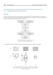
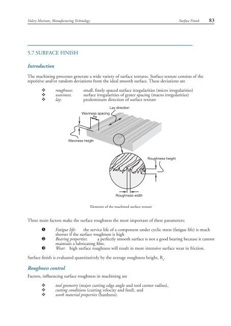
<strong>5.7</strong> SURFACE FINISH<br />
Introduction<br />
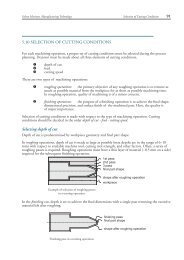
The machining processes generate a wide variety of surface textures. <strong>Surface</strong> texture consists of the<br />
repetitive and/or random deviations from the ideal smooth surface. These deviations are<br />
v roughness: small, finely spaced surface irregularities (micro irregularities)<br />
v waviness: surface irregularities of grater spacing (macro irregularities)<br />
v lay: predominant direction of surface texture<br />
Waviness spacing<br />
Lay direction<br />
Waviness heigth<br />
Roughness height<br />
Roughness width<br />
Elements of the machined surface texture<br />
Three main factors make the surface roughness the most important of these parameters:<br />
Fatigue life: the service life of a component under cyclic stress (fatigue life) is much<br />
shorter if the surface roughness is high<br />
Bearing properties: a perfectly smooth surface is not a good bearing because it cannot<br />
maintain a lubricating film.<br />
Wear: high surface roughness will result in more intensive surface wear in friction.<br />
<strong>Surface</strong> finish is evaluated quantitatively by the average roughness height, R a<br />
.<br />
Roughness control<br />
Factors, influencing surface roughness in machining are<br />
v<br />
v<br />
v<br />
tool geometry (major cutting edge angle and tool corner radius),<br />
cutting conditions (cutting velocity and feed), and<br />
work material properties (hardness).
84 <strong>Surface</strong> <strong>Finish</strong><br />
Valery Marinov, Manufacturing Technology<br />
Feed marks<br />
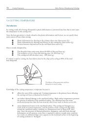
During cutting with a single point cutting tool (e.g. turning), the tool leaves a spiral profile on the<br />
machined surface as it moves across the workpiece, so called feed marks. The height of the feed marks is<br />
nothing but the surface roughness height and can be assumed equal to R a<br />
. From the figure, it is evident<br />
that the feed and the geometry of the cutting tool determine the value of R a<br />
:<br />
d<br />
Ra<br />
r<br />
r r<br />
feed<br />
V<br />
r<br />
Ra<br />
Direction of feed motion<br />
tool position after<br />
one full revolution<br />
of the workpiece<br />
feed<br />
tool initial position<br />
<br />
<br />
Definition of the average surface roughness height R a<br />
From geometrical considerations, the theoretical surface roughness R`a is approximately defined by<br />
R`a = f 2 /32r ∈<br />
where f is the feed, and r ∈<br />
is the tool corner radius.<br />
In case of machining with multi-point cutting tools or abrasive tools, the geometrical considerations are<br />
much more complex but the general tendency is the same.<br />
From the above equation, it follows that feed is the primary machining parameter to change in order<br />
to control the surface roughness as far as changing the tool corner radius is much less convenient. The<br />
other process parameters - cutting speed, rake angle, and work material hardness, also influence the<br />
surface finish although not to the same extend as feed. The relationships between surface roughness and<br />
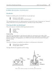
cutting conditions are shown in the figures:<br />
materials, which<br />
form built-up edge<br />
R a<br />
feed, f cutting speed, V<br />
materials, which<br />
do not form built-up edge<br />
<strong>Surface</strong> roughness versus cutting speed and feed<br />
For very low feeds, surface roughness worsens. The reason is a change in the nature of metal cutting<br />
process. The influence of cutting speed is more complex for materials, which tend to form built-up edge<br />
at low speeds. The influence of built-up edge on surface finish is discussed in Section 5.2 Mechanics of<br />
Machining. Depth of cut has secondary effect on surface finish.<br />
One major conclusion could be drawn from the above figures - best surface finish is achieved when<br />
cutting at high speed with low feed, a combination typical for finishing machining.
Valery Marinov, Manufacturing Technology<br />
<strong>Surface</strong> <strong>Finish</strong> 85<br />
The influence of the other process parameters is outlined below:<br />
v<br />
v<br />
v<br />
v<br />
Increasing the tool rake angle generally improves surface finish<br />
Higher work material hardness results in better surface finish<br />
Tool material has minor effect on surface finish.<br />
Cutting fluids affect the surface finish changing cutting temperature and as a result the<br />
built-up edge formation.<br />
The cumulative effect of these and other process parameters can be taken into account by an empirical<br />
correction coefficient r ai<br />
defined from the next figure:<br />
r ai<br />
1.75<br />
ductile materials<br />
1.50<br />
1.25<br />
1.00<br />
cast iron<br />
free machining alloys<br />
40 60 80 100 120<br />
cutting speed, m/min<br />
Correction coefficient to account for the influence of work material and cutting speed<br />
on surface finish<br />
The corrected value of R a<br />
is calculated as<br />
R a<br />
= r ai<br />
R`a<br />
where the theoretical surface roughness R`a is defined as shown before.