Wärtsilä Medium-Speed Marine Diesel Engines
Wärtsilä Medium-Speed Marine Diesel Engines
Wärtsilä Medium-Speed Marine Diesel Engines

Create successful ePaper yourself
Turn your PDF publications into a flip-book with our unique Google optimized e-Paper software.
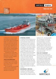
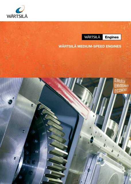
WÄRTSILÄ MEDIUM-SPEED ENGINES
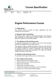
The Oasis of the Seas, equipped with six Wärtsilä 46 engines.<br />
MEDIUM-SPEED ENGINES<br />
<strong>Medium</strong>-speed diesel and dual-fuel<br />
engines for reliability<br />
and total economy .................................3<br />
Compliance with environmental<br />
regulations and other standards............4<br />
Main features.........................................4<br />
Engine performance ..............................5<br />
Engine design ........................................6<br />
Engine block......................................6<br />
Crankshaft and bearings.....................6<br />
Connecting rod ..................................7<br />
Cylinder liner and antipolishing ring.....7<br />
Piston & piston rings ..........................8<br />
Cylinder head.....................................8<br />
Multiduct ...........................................9<br />
Camshaft and valve gear ....................9<br />
Operational systems<br />
Fuel injection system........................10<br />
Turbocharging system ......................11<br />
Cooling system ................................12<br />
Lubricating oil system.......................12<br />
Automation system ..........................12<br />
Dual-fuel technology ...........................14<br />
Maintenance features..........................18<br />
Services ..............................................18<br />
2<br />
The Thetis, equipped with a Wärtsilä 20 engine.<br />
POWER RANGE FOR WÄRTSILÄ MEDIUMSPEED ENGINES<br />
DIESEL ENGINES<br />
Wärtsilä 20<br />
Wärtsilä 26<br />
Wärtsilä 32<br />
Wärtsilä 38<br />
Wärtsilä 46<br />
Wärtsilä 46F<br />
Wärtsilä 64<br />
DUALFUEL ENGINES<br />
Wärtsilä 20DF<br />
Wärtsilä 34DF<br />
Wärtsilä 50DF<br />
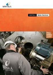
The submersible heavy load ship Blue Marlin is<br />
equipped with three Wärtsilä 8L32 engines.<br />
kW 5000 10,000 15,000 20,000 25,000
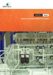
The LNG Tanker, GDF-Suez Global Energy is equipped with four Wärtsilä 50DF engines.<br />
The Naval vessel De Zeven Provincien is equipped with<br />
two Wärtsilä 16V26 engines.<br />
The tanker Bitflower is equipped with a<br />
Wärtsilä 6L38 engine.<br />
MEDIUM-SPEED DIESEL AND DUAL-FUEL ENGINES<br />
FOR RELIABILITY AND TOTAL ECONOMY<br />
The design of the Wärtsilä medium-speed<br />
engine range is based on the vast amount<br />
of knowledge accumulated over years of<br />
successful operation.<br />
Robust engines and generating sets,<br />
developed from pioneering heavy fuel<br />
technology, have been engineered to provide<br />
unquestionable benefits for the owners and<br />
operators of marine vessels.<br />
These benefits include:<br />
•Proven reliability<br />
•Low emissions<br />
•Low operating costs<br />
•Fuel flexibility<br />
•Integrated system solutions<br />
•All services from spare parts to<br />
reconditioning available from Wärtsilä’s<br />
global network<br />
In shipyard applications, the installation<br />
friendliness, embedded automation system,<br />
and built-on modularized auxiliary systems are<br />
amongst the many added advantages.<br />
Wärtsilä is continuously developing its<br />
portfolio of gas and multi-fuel engines to suit<br />
different marine applications, offshore oil<br />
and gas installations where gaseous fuel is<br />
available from the process, and merchant<br />
vessels operating in environmentally<br />
sensitive areas. Wärtsilä engines offer high<br />
efficiency, low exhaust gas emissions, and<br />
safe operation. The innovative multi-fuel<br />
technology allows the flexibility to choose<br />
between gas or liquid fuel. When necessary,<br />
the engines are capable of switching from<br />
one fuel to the other without any interruption<br />
in power generation.<br />
3
COMPLIANCE WITH ENVIRONMENTAL REGULATIONS AND OTHER STANDARDS<br />
Environmental issues, especially emissions<br />
reduction and fuel consumption, have<br />
become increasingly important in the<br />
shipping sector where enforcement of<br />
environmental regulations, at both global<br />
and local levels, has notably increased. This<br />
puts pressure on the marine industry to<br />
constantly explore new ways of reducing the<br />
environmental impact of ships.<br />
Wärtsilä creates added value for its<br />
customers by providing products, solutions<br />
and services that fulfill their needs and<br />
expectations. The development of highquality,<br />
reliable, and environmentally<br />
sound solutions and services has come<br />
as a result of long-term collaboration and<br />
continuous interaction with our customers.<br />
We provide service support to ensure<br />
optimal performance throughout the product<br />
lifecycle. The upgrading of installed products<br />
can also extend their service life.<br />
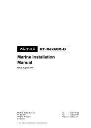
20<br />
18<br />
16<br />
14<br />
12<br />
10<br />
8<br />
6<br />
4<br />
2<br />
0<br />
NOx emissions, g/kWh<br />
IMO Tier I, 2000<br />
IMO Tier II, 2011<br />
IMO Tier III, 2016 in emission control areas<br />
0 200 400 600 800 1000 1200 1400 1600<br />
Engine speed, rpm<br />
WÄRTSILÄ MEETS THE NEW<br />
REQUIREMENTS ON SHIP EMISSIONS<br />
The International Maritime Organization (IMO)<br />
has approved amendments to the MARPOL<br />
Annex VI regulations on ship emissions. These<br />
regulations set stricter limits on emissions<br />
of Nitrogen Oxides (NO X ) from the engines,<br />
as well as on the sulphur content of the fuel.<br />
The new requirements will enter into force in<br />
various phases during the years 2010–2020.<br />
As regards NO X emissions, Wärtsilä has<br />
already introduced solutions that comply with<br />
these requirements. Wärtsilä engines are<br />
designed for operation on any fuel sulphur<br />
content. As a response to the tightening<br />
Sulfur Oxides (SO X ) emissions, Wärtsilä has<br />
developed scrubber technology that allows<br />
exhaust gases to be cleaned to meet the tight<br />
regulations.<br />
GAS ENGINES HIGHLIGHTED<br />
Wärtsilä has a multifaceted gas engine<br />
strategy, and can provide gas engines<br />
for vessels. Being at the forefront of<br />
technological developments gives Wärtsilä<br />
many opportunities arising from the tightening<br />
environmental regulations. Shipping can<br />
reduce its carbon footprint through ship<br />
design, efficient engines, and optimal<br />
propulsion solutions.<br />
MAIN FEATURES<br />
Wärtsilä engines offer outstanding powerto-weight<br />
and power-to-space ratios in their<br />
power range. They have bore sizes from 200 to<br />
640 mm and different cylinder configurations<br />
to cover a power range from 0.5 MW to<br />
20 MW and are capable of using various fuels.<br />
Wärtsilä 4-stroke engines comply with both<br />
IMO Tier I and IMO Tier II emission legislation<br />
without secondary purification systems.<br />
Full advantage is taken of the proven<br />
solutions developed in earlier Wärtsilä engines,<br />
while new features and customer benefits<br />
have been added. Reliability and total economy<br />
are the guiding principles, although emission<br />
control options and installation friendliness are<br />
strongly emphasized.<br />
• Cylinder power from 185 kW to 2150 kW<br />
• Nominal speed from 500 to 1000 rpm<br />
• Multi-fuel operation capability<br />
• High thermal efficiency and low emissions<br />
• High reliability and low maintenance costs<br />
• Low exhaust gas emissions<br />
• Fuel economy throughout the entire engine<br />
operational range<br />
• Embedded automation system including<br />
speed control<br />
4
ENGINE PERFORMANCE<br />
Wärtsilä 4-stroke engines utilize the latest<br />
developments in turbo-charging technology, which<br />
enables Miller valve timing and the Variable Inlet<br />
Valve Closing (VIC) system to be employed.<br />
At full-load operation, early closure of the<br />
inlet valves enables a low effective compression<br />
ratio, and as a result, comparatively low<br />
temperatures at the end of the compression<br />
stroke. The charge air, being both somewhat<br />
expanded and cooled on its way through the<br />
receiver into the cylinders, has a low global<br />
temperature that is still high enough to<br />
guarantee reliable and stable ignition of the<br />
fuel/air mixture in the combustion chamber.<br />
This contributes to the creation of favourable<br />
conditions for an environmentally friendly<br />
combustion process.<br />
In Wärtsilä engines, these advantageous<br />
initial conditions are combined with a higher<br />
engine speed and a high expansion ratio,<br />
i.e. with design parameters that make the<br />
combustion chamber expand quickly when<br />
the combustion process has started. Due to<br />
the quick expansion of the combustion gases,<br />
high temperatures that are most critical to the<br />
formation of intensive NO X within the combustion<br />
chamber are rapidly abated. This combination<br />
creates a combustion process that is not only<br />
environmentally friendly, but also extremely<br />
efficient as the high expansion ratio produces<br />
the conditions needed for efficient utilization of<br />
the heat energy released by combustion at the<br />
beginning of the power stroke.<br />
However, it is not only the choice of the<br />
compression/expansion ratio that makes<br />
Wärtsilä engines highly efficient. All versions<br />
of the engine are equipped with fuel injection<br />
systems that allow adjustment of the injection<br />
characteristics to the prevailing load conditions.<br />
The advanced common-rail fuel injection<br />
system offers the freedom to control and finetune<br />
the injection process. This enables full use<br />
of the engine’s loading potential over a wide<br />
power range in order to achieve optimum fuel<br />
economy. Similarly, this freedom offered by the<br />
flexible fuel injection equipment can be utilized<br />
to adjust the engine to the existing limitations<br />
of exhaust gas emissions, to minimize smoke<br />
formation. Thermal load and mechanical stress<br />
levels are kept within the safety margins<br />
established by Wärtsilä over decades of engine<br />
development.<br />
5
ENGINE DESIGN<br />
ENGINE BLOCK<br />
Nodular cast iron is the natural choice for<br />
engine blocks today because of its strength<br />
and stiffness properties. Wärtsilä engine monoblock<br />
designs are based on modern foundry<br />
technology to integrate most oil and water<br />
channels, as well as the charge air receiver.<br />
The result is a virtually pipe-free engine with a<br />
clean outer exterior.<br />
Resilient mounting, available as an option,<br />
is required in many application types. The<br />
engine block has been designed especially for<br />
this purpose. Integrated channels designed<br />
with this in mind serve a double purpose.<br />
CRANKSHAFT AND BEARINGS<br />
The latest advances in combustion<br />
development require a crank gear that can<br />
operate reliably at high cylinder pressures.<br />
The crankshaft must be robust and the<br />
specific bearing loads kept at a safe level.<br />
This is achieved by careful optimization of the<br />
crankshaft’s throw dimensions and fillets. The<br />
specific bearing loads are conservative and<br />
the cylinder spacing, which is important to<br />
the overall length of the engine, is minimized.<br />
Besides low bearing loads, the other crucial<br />
factor for safe bearing operation is oil film<br />
thickness. Ample oil film thickness in the main<br />
bearings is ensured by optimal balancing of the<br />
rotational masses and, in the big end bearing,<br />
by ungrooved bearing surfaces in the critical<br />
areas. All the factors needed for a free choice<br />
of the most appropriate bearing material are<br />
present..<br />
The main features of the crankshaft and<br />
bearings design are:<br />
•Clean steel technology to minimize the<br />
amount of slag forming elements, and to<br />
guarantee superior material properties<br />
•A crankshaft line assembled from three<br />
elements: the crankshaft, gear and end<br />
piece. The crankshaft itself is forged in one<br />
piece<br />
•Each throw is fully balanced individually for<br />
safe bearing function<br />
•Main bearing temperature monitoring<br />
•Patented crankpin bearing temperature<br />
monitoring<br />
•Modest bearing loads thanks to generous<br />
bearing dimensions.<br />
CONNECTING ROD<br />
The three-piece connecting rod is of the<br />
marine type used in Wärtsilä engines having<br />
a cylinder power of more than 400 kW, where<br />
the combustion forces are distributed over<br />
a maximum bearing area, and the relative<br />
movements between mating surfaces are<br />
minimized. The connecting rod is optimized for<br />
6
oth strength and weight. The shank is fully<br />
machined. The three-piece design simplifies<br />
piston overhauling, as this can be carried out<br />
without touching the big end bearing. The big<br />
end bearing can also be inspected without<br />
removing the piston.<br />
The two-piece design is used for smaller<br />
engines having a cylinder power of less than<br />
400 kW. The design offers the maximum pin<br />
diameter while still making it possible to pull<br />
the connecting rod through the cylinder liner.<br />
The main features of the connecting rod<br />
design are:<br />
•Two/three-piece type design depending on<br />
engine size<br />
•Hydraulically tightened bolts<br />
•Both strength and weight are optimized<br />
•Easy maintenance<br />
CYLINDER LINER AND ANTIPOLISHING RING<br />
The cylinder liner is designed to have the<br />
stiffness needed to withstand both pretension<br />
forces and combustion pressures with virtually<br />
no deformation. This gives the best cylinder<br />
function and ensures good basics for the<br />
tightness of the cylinder head gasket. The<br />
temperature is controlled by optimizing the<br />
cooling water flow in the upper part of the<br />
collar to achieve a low thermal load, and to<br />
avoid sulphuric acid corrosion.<br />
The liner is made of wear-resistant material<br />
developed from a dedicated and long-term<br />
R&D programme. To eliminate the risk of bore<br />
polishing, the liner is provided with an antipolishing<br />
ring on the upper part. The purpose<br />
of this ring is to limit the carbon deposits<br />
built up on the piston top land to a thickness<br />
small enough to prevent contact between<br />
the inner liner wall and the deposits on any<br />
position of the piston. The absence of contact<br />
between the liner and piston top land deposits<br />
eliminates the risk of bore polishing. Nor can<br />
oil be scraped upwards by the piston. This<br />
significantly reduces liner wear and keeps the<br />
lube oil consumption stable for long periods of<br />
time.<br />
The main features of the cylinder liner<br />
design are:<br />
•Centrifugal casting with high strength and<br />
good wear resistance<br />
•Cooling of the bore for optimum wall<br />
temperatures<br />
•High-collar technology to ensure good<br />
cylinder head gasket tightness<br />
•Anti-polishing ring removes deposits from<br />
the piston top land, ensuring proper cylinder<br />
function, no bore polishing, stable lube oil<br />
consumption, and low wear to the liner.<br />
7
PISTON & PISTON RINGS<br />
For years, the outstanding piston concept<br />
for highly rated heavy fuel engines has been<br />
a rigid composite piston with a steel crown<br />
and nodular cast-iron skirt. More than twenty<br />
years of experience has fine-tuned this<br />
concept. When it comes to reliability, there is<br />
no real alternative today for modern engines<br />
with high cylinder pressures and combustion<br />
temperatures.<br />
Wärtsilä’s patented skirt lubrication<br />
minimizes frictional losses, and ensures the<br />
appropriate lubrication of both piston rings and<br />
the piston skirt. In Wärtsilä’s three-ring concept<br />
each ring has a specific task. The rings are<br />
dimensioned and profiled for consistent<br />
performance throughout their operating lives.<br />
To avoid carbon deposits in the ring<br />
grooves of a heavy fuel engine, the pressure<br />
balance above and below each ring is crucial.<br />
Experience has shown that this effect is most<br />
likely achieved with a three-ring pack. Finally,<br />
it is well known that most frictional losses in<br />
a reciprocating combustion engine originate<br />
from the rings. Thus a three-ring pack is the<br />
obvious choice in this respect, too. The piston<br />
ring package and ring grooves are optimized<br />
for long life by a special wear-resistant coating<br />
and groove treatment.<br />
The main features of the piston design are:<br />
•A two-piece composite structure<br />
•A steel crown and nodular cast-iron skirt<br />
•Two compression rings and one oil scraper<br />
ring, which in combination with a pressure<br />
lubricated piston skirt, achieve low friction<br />
and high seizure resistance<br />
•Optimized piston ring groove temperature to<br />
prevent cold corrosion.<br />
CYLINDER HEAD<br />
The cylinder head design features high<br />
reliability and easy maintenance. A stiff cone- /<br />
box-like design can cope with high combustion<br />
pressures, and is essential for obtaining both<br />
liner roundness and even contact between the<br />
exhaust valves and their seats. Wärtsilä’s vast<br />
global experience of heavy fuel operation has<br />
contributed greatly to the efficient design and<br />
development of exhaust valves.<br />
The basic criterion in exhaust valve design<br />
is having the correct temperature. This is<br />
achieved through optimized cooling and closed<br />
seat ring technology, which extend the life of<br />
the valves and seats.<br />
The cylinder head design is based on the<br />
four-screw concept developed and used by<br />
Wärtsilä for many years. A four-screw cylinder<br />
head design also provides the possibility<br />
for having inlet and exhaust ports with a<br />
minimum of flow losses. The port design<br />
has been optimized using a combination of<br />
computational fluid dynamics analysis and fullscale<br />
flow measurements.<br />
The main features of the cylinder head design<br />
are:<br />
•Four cylinder head screws only, giving<br />
space for flow-efficient ports<br />
•Inlet and exhaust gas ports that are on the<br />
same side<br />
•The height and rigid design, which ensure<br />
even and sufficient surface pressure on the<br />
cylinder head gasket<br />
•A bore-cooled flame plate for optimum<br />
temperature distribution<br />
•Two inlet valves and two exhaust gas<br />
valves, all with valve rotators.<br />
8
MULTI-DUCT<br />
A multifunctional duct is connected to the<br />
cylinder head. The functions of this multi-duct<br />
are as follows:<br />
•Air transfer from air receiver to cylinder head<br />
•Introduction of an initial swirl to the inlet air<br />
for optimal part load combustion<br />
•Exhaust transfer to the exhaust system<br />
•Cooling water transfer from the cylinder<br />
head to the return channel in the engine<br />
block<br />
•Insulation/cooling of the exhaust transfer<br />
duct<br />
•Support for the exhaust system, including<br />
insulation<br />
CAMSHAFT AND VALVE GEAR<br />
The engine is available with either traditional<br />
mechanical valve actuation, or variable inlet<br />
valve closing actuation.<br />
The camshaft is built of single cylinder<br />
sections with integrated cams. The camshaft<br />
sections are connected through separate<br />
bearing journals, which make it possible to<br />
remove the shaft sections sideways from the<br />
camshaft compartment.<br />
The valve follower is of the roller tappet<br />
type, where the roller profile is slightly<br />
convex for good load distribution. The valve<br />
mechanism includes rocker arms working on<br />
yokes guided by pins.<br />
Both exhaust and inlet valves are equipped<br />
with valve rotators to ensure a safe valve and<br />
seat function. The rotation means that the<br />
temperature distribution and wear to the valves<br />
is even, and that the sealing surface is kept<br />
free of deposits.<br />
The main features of the camshaft and valve<br />
design are:<br />
•Each cylinder section of the camshaft is<br />
forged in one piece with integrated cams<br />
•Separate bearing journals<br />
•The valve follower is of the roller tappet type<br />
•Traditional valve actuation<br />
•Variable Inlet Valve Closing (VIC) for<br />
IMO Tier II compliance.<br />
The VIC system is designed to improve the<br />
engine’s partial load performance by enabling<br />
alternative inlet valve closing timings. The<br />
major advantages are a reduction in visible<br />
smoke, load application improvement, and<br />
thermal load reduction. The variation of inlet<br />
valve closing timing is achieved through the<br />
addition of a hydraulic chamber between<br />
the inlet valve tappet and the push rod.<br />
Adjustability of the inlet valve movement is<br />
achieved by controlling the oil flow into and out<br />
the hydraulic chamber.<br />
The main features of the VIC system are:<br />
•Inlet valve closing timing that can be<br />
adjusted<br />
•With VIC employed, the inlet valve is open<br />
longer<br />
As compared to the standard valve train, the<br />
VIC system comprises the following additional<br />
parts:<br />
•Pressure accumulator<br />
•Piston and oil supply<br />
•Non-return valve<br />
9
OPERATIONAL SYSTEMS<br />
FUEL INJECTION SYSTEM<br />
The patented Wärtsilä multi-housing principle<br />
ensures outstanding safety of the low-pressure<br />
fuel system. The fuel line consists of channels<br />
drilled in cast parts, which are clamped firmly<br />
to the engine block. For easy assembly and<br />
disassembly, these parts are connected to<br />
each other using slide connections.<br />
Wärtsilä 4-stroke engines are available<br />
with three alternative fuel injection systems<br />
depending on configuration: a conventional<br />
fuel injection system, with either single- or<br />
twin plunger injection pumps, and commonrail<br />
fuel injection. High injection pressures<br />
giving low smoke emissions characterize all<br />
three systems. The common-rail technology<br />
in particular, enables operation at any load<br />
without visible smoke.<br />
An unmatched level of safety is achieved<br />
through housing both the entire low-pressure<br />
and high-pressure systems in a fully covered<br />
compartment.<br />
Common-rail technology offers almost<br />
unlimited possibilities to adjust the fuel<br />
injection process to the prevailing engine<br />
operating conditions, fuel characteristics,<br />
and to achieve emission levels. The main<br />
components of the common-rail injection<br />
system that are designed especially for<br />
Wärtsilä engines are the high-pressure pumps,<br />
the balance accumulators, the fuel injection<br />
valves, and the built-on control oil pump. The<br />
control oil is engine oil with additional filtration.<br />
The system’s high-pressure pumps are<br />
camshaft-driven and amply dimensioned for<br />
supplying fuel to two cylinders. Each pump is<br />
connected to a fuel accumulator that evens<br />
out the pressure and feeds the two cylinders.<br />
The accumulators are connected to each other<br />
through double-walled pipes, a detail that<br />
both guarantees continuously even pressure<br />
in all accumulators, and that allows the engine<br />
to operate with one or two disconnected<br />
high-pressure pumps, should this ever be<br />
necessary.<br />
From the accumulators, fuel is supplied<br />
at the required pressure into the cylinders<br />
through injection valves controlled by electrohydraulic<br />
actuators. The individual, and<br />
therefore cylinder-specific, control of injection<br />
timing and duration is an important feature that<br />
is made possible by this injection equipment.<br />
One significant safety detail is that the<br />
injection valves are designed to ensure that the<br />
10
injection nozzles are totally unloaded between<br />
injection periods. This feature eliminates the<br />
risk of unintended fuel supply into the cylinders<br />
caused, for example, by incomplete closure of<br />
the nozzle needle at the end of injection.<br />
The twin-pump system, likewise, offers the<br />
possibility to optimize the prevailing engine<br />
operating conditions, fuel characteristics and<br />
emission levels, thanks to twin plunger pump<br />
elements. One plunger controls the quantity<br />
of fuel while the other controls the injection<br />
timing.<br />
TURBOCHARGING SYSTEM<br />
Turbocharger technology has undergone<br />
intense design and performance development<br />
in recent years, resulting in higher performance<br />
and greater reliability. Only the best available<br />
charger technology is used on Wärtsilä<br />
engines.<br />
The main features of the turbocharging<br />
system are:<br />
•One-stage turbocharging<br />
•An oil-cooled turbocharger with plain<br />
bearings lubricated by engine oil<br />
•A two-stage charge air cooler depending on<br />
engine configuration<br />
•An LT water bypass valve for charge air<br />
temperature control<br />
•The charge air receiver is integrated into<br />
the engine block<br />
•A water mist catcher as a standard option<br />
•Air and exhaust waste gate functions for<br />
best engine performance, depending on<br />
engine configuration<br />
•A single-pipe exhaust gas system (SPEX)<br />
or pulse charging, depending on engine<br />
configuration<br />
The SPEX system is designed for minimum<br />
flow losses on both the exhaust and air sides.<br />
The charging systems are designed to give<br />
high efficiency and good load acceptance.<br />
SPEX is designed for best possible full-load<br />
performance. SPEX, combined with the<br />
exhaust waste gate and air bypass, meets<br />
the established low load performance of<br />
pulse charging. With its unique design, the<br />
load acceptance is close to that of pulse<br />
charging. Non-cooled chargers, with inboard<br />
plain bearings lubricated by the engine’s lube<br />
oil system, are used. The end result is that<br />
intervals between overhauls are reduced, as is<br />
maintenance.<br />
11
Lubricating<br />
oil<br />
cooler<br />
Charge<br />
air cooler<br />
LT<br />
Heat recovery<br />
Charge<br />
air cooler<br />
HT<br />
Cyl.<br />
Central<br />
cooler<br />
LT<br />
standby<br />
pump<br />
LT<br />
pump<br />
HT<br />
pump<br />
HT<br />
standby<br />
pump<br />
Preheater<br />
PRINCIPLE LAYOUT OF THE COOLING SYSTEM.<br />
Automatic filter<br />
Oil cooler<br />
Oil pump<br />
Electric<br />
standby<br />
oil pump<br />
Centrifugal filter<br />
Electric<br />
prelube<br />
oil pump<br />
Dry oil sump<br />
Suction<br />
strainer<br />
System oil tank<br />
PRINCIPLE LAYOUT OF THE LUBRICATING SYSTEM.<br />
COOLING SYSTEM<br />
The cooling system on the engine is split<br />
into two separate circuits: high-temperature<br />
(HT) and low-temperature (LT). The cylinder<br />
liner, the cylinder head, and the first stage<br />
in the charge air cooler are all connected to<br />
the HT circuit. The lubricating oil cooler and<br />
the second stage in the charge air cooler are<br />
connected to the LT circuit.<br />
The amount of water passing through the<br />
LT stage in the charge air cooler is controlled<br />
by a thermostatic valve. This maintains the<br />
desired intake air temperature, regardless of<br />
load level or variations in the cooling water<br />
temperature. Engine-driven pumps and builton<br />
thermostatic valves are standard. As an<br />
option, the engine is also available without<br />
built-on pumps and thermostatic valves.<br />
LUBRICATING OIL SYSTEM<br />
The engine is available with a complete builton<br />
lube oil system that offers the following<br />
features:<br />
•An engine-driven main lube oil pump (screw<br />
type) with built-in safety valve<br />
•A pressure regulating valve that keeps the<br />
pressure before the main bearings at a<br />
constant level<br />
•A lubricating oil module, including lube oil<br />
cooler, filter and thermostatic valves<br />
•The lube oil filtration is based on a full flow<br />
automatic back-flushing filter. This requires<br />
a minimum of maintenance and needs no<br />
disposable filter cartridges<br />
•A centrifugal filter connected to the backflushing<br />
line of the automatic filter. This<br />
enables wear particles from the system to<br />
be extracted<br />
•An electric motor driven pre-lubricating<br />
pump, depending on engine configuration<br />
•The oil sump is either a wet or dry type,<br />
depending on engine configuration. A<br />
separate system oil tank is needed for the<br />
dry sump<br />
•Connections for stand-by auxiliaries.<br />
AUTOMATION SYSTEM<br />
Wärtsilä engines can be equipped with a<br />
modular embedded automation system, the<br />
Wärtsilä Unified Controls – UNIC, which is<br />
available in three different versions. The basic<br />
functionality is the same in all versions, but<br />
the functionality can be easily expanded to<br />
cover different applications. UNIC C1 and<br />
UNIC C2 are versions applicable for engines<br />
with conventional fuel injection, whereas UNIC<br />
C3 additionally includes fuel injection control<br />
12
IOM<br />
Hardwired<br />
connections<br />
Loadsh.<br />
CAN<br />
Ethernet<br />
LDU<br />
LCP<br />
CCM<br />
CCM<br />
ESM<br />
MCM<br />
PDM<br />
UNIC<br />
for engines with common-rail fuel injection.<br />
UNIC C3 automation is also used in gas<br />
engines.<br />
The Wärtsilä UNIC is a flexible and fully<br />
scalable control system for large reciprocating<br />
diesel and gas engines.<br />
The UNIC system is designed to fulfill the<br />
long lifetime expectations for large marine<br />
diesel and gas engines operating in the<br />
toughest of conditions. The system is based<br />
on a high degree of commonalities and<br />
standard interfaces, covering different engine<br />
sizes and fuel systems in a modular way.<br />
A modular, standardized interface provides<br />
an easily reusable design for off-engine<br />
automation systems. It allows, for example,<br />
diesel engines to be converted to dual fuel or<br />
common rail with a minimum of modifications.<br />
Thanks to the pre-tested configuration,<br />
minimal commissioning or installation work<br />
is needed before the engine or generating<br />
set is operational. The critical parts of the<br />
UNIC system are either redundant or very<br />
fault-tolerant to guarantee high safety and<br />
availability in all circumstances. In particular,<br />
parts like the communication and power supply<br />
are fully redundant to allow single failures<br />
without interruptions in engine operation.<br />
The electronic control enables the engine to<br />
be adapted to different operating conditions.<br />
The main features of the UNIC system are:<br />
•A complete engine safety system<br />
•Local monitoring<br />
•<strong>Speed</strong> control with load sharing<br />
•Fuel injection<br />
•Timing control and knock detection<br />
•Alarm signal acquisition<br />
AUTOMATION SYSTEM COMPONENTS<br />
ESM<br />
MCM<br />
TCM<br />
IOM<br />
PDM<br />
LCP<br />
LDU<br />
CCM<br />
Engine Safety Module<br />
Main Control Module<br />
Thermocouple Module<br />
Input Output Module<br />
Power Distribution Module<br />
Local Control Panel<br />
Local Display Unit<br />
Cylinder Control Module<br />
•Start/stop sequencing and load reduction<br />
request<br />
•System diagnostics and a fieldbus interface<br />
applicable to each engine’s configuration.<br />
13
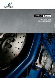
BMEP (bar)<br />
Knocking<br />
Operating<br />
window<br />
45%<br />
0.6 0.8 1.0 1.2 1.4 1.6 1.8 2.0 2.2<br />
Air/fuel ratio<br />
2 g/kWh<br />
2.4<br />
Misfiring<br />
2.6<br />
Thermal efficiency (%)<br />
NO (g/kWh)<br />
X<br />
DUAL-FUEL TECHNOLOGY<br />
THE LEAN-BURN CONCEPT<br />
The Wärtsilä dual-fuel technology operates<br />
on the lean-burn principle: the mixture of air<br />
and gas in the cylinder has more air than<br />
is needed for complete combustion. Lean<br />
combustion reduces peak temperatures<br />
and therefore NO X emissions. Efficiency<br />
is increased and higher output is reached<br />
while avoiding knocking.<br />
Combustion of the lean air-fuel mixture<br />
is initiated by injecting a small amount of<br />
LFO (pilot fuel) into the cylinder. The pilot<br />
fuel is ignited in a conventional diesel<br />
process, providing a high-energy ignition<br />
source for the main charge. To obtain the<br />
best efficiency and lowest emissions, every<br />
cylinder is individually controlled to ensure<br />
operation at the correct air-fuel ratio and<br />
with the correct amount and timing of pilot<br />
fuel injection.<br />
Wärtsilä has developed a special<br />
electronic control system to cope with<br />
the demanding task of controlling the<br />
combustion in each cylinder, and to ensure<br />
optimal performance in terms of efficiency<br />
and emissions under all conditions by<br />
keeping each cylinder within the operating<br />
window. Stable and well-controlled<br />
combustion also contributes to less<br />
mechanical and thermal load on the engine<br />
components.<br />
FUEL SYSTEM<br />
The fuel system of the Wärtsilä dual-fuel engine<br />
has been divided into three: for gas, for liquid fuel,<br />
and for a separate pilot fuel system. The Wärtsilä<br />
dual-fuel engine is started in diesel mode using<br />
both main diesel and pilot fuel. Gas admission<br />
is activated when combustion is stable in all<br />
cylinders. When running the engine in gas mode,<br />
the pilot fuel amounts to less than 1% of full-load<br />
fuel consumption. The amount of pilot fuel is<br />
controlled by the engine control system. When<br />
running the engine in liquid fuel mode the pilot is<br />
also in use to ensure nozzle cooling.<br />
GAS SUPPLY<br />
The natural gas is supplied to the engine<br />
through a gas valve unit. The gas is first filtered<br />
to ensure a clean supply. The gas pressure<br />
is controlled by a valve located in the valve<br />
station. The gas pressure is dependent on<br />
engine load. At full load the pressure before<br />
the engine is 3.5 bar (g) for LHV 36 MJ/m 3 .<br />
For lower LHV the pressure has to be<br />
increased. The system includes the necessary<br />
shut-off and venting valves to ensure a safe<br />
and trouble-free gas supply.<br />
On the engine, the gas is supplied through<br />
large common-rail pipes running along the<br />
engine. Each cylinder then has an individual<br />
feed pipe to the gas admission valve on the<br />
cylinder head.<br />
Gas piping in marine installations is of<br />
double wall design as standard.<br />
LIQUID FUEL OIL SUPPLY<br />
The fuel oil supply on the engine is divided into<br />
two separate systems: pilot fuel and back-up<br />
fuel oil system.<br />
The pilot fuel is elevated to the required<br />
pressure by a pump unit. This includes<br />
duplex filters, pressure regulator and an<br />
engine-driven radial piston-type pump. The<br />
high-pressure pilot fuel is then distributed<br />
through a common-rail pipe to the injection<br />
valves at each cylinder. Pilot fuel is injected at<br />
approximately 900 bar pressure and the timing<br />
and duration are electronically controlled. The<br />
pilot fuel system is separated from the back-up<br />
fuel system with separate connections on the<br />
engine. The back-up fuel system is fed to a<br />
normal camshaft-driven injection pump. From<br />
the injection pump, the high-pressure fuel goes<br />
to a spring-loaded injection valve of standard<br />
design for a diesel engine.<br />
INJECTION VALVE<br />
The Wärtsilä dual-fuel has a twin-needle<br />
injection valve. The larger needle is used in<br />
back-up mode for LFO or HFO operation and<br />
the smaller for pilot fuel oil when the engine<br />
is running in gas mode and also in back-up<br />
fuel operation to ensure nozzle cooling. Pilot<br />
14
RETURN FUEL<br />
FUEL INJECTION PUMPS FOR<br />
LIQUID FUEL OPERATION<br />
INJECTION VALVES<br />
BOOSTER<br />
PUMP<br />
UNIT<br />
BOOSTER<br />
PUMP<br />
UNIT<br />
PRESSURE<br />
PRESSURE<br />
M<br />
Control<br />
system<br />
PRESSURE<br />
COMMON RAIL FOR HIGH<br />
PRESSURE PILOT FUEL<br />
RETURN FUEL<br />
PILOT FUEL PUMP UNIT<br />
MAIN FUEL TANK<br />
LFO or HFO<br />
PILOT FUEL TANK<br />
LFO<br />
injection is electronically controlled and the<br />
main diesel injection is hydromechanically<br />
controlled. The individually controlled solenoid<br />
valve allows optimum timing and duration of<br />
pilot fuel injection into every cylinder when<br />
the engine is running in gas mode. Since NO X<br />
formation depends greatly on the amount of<br />
pilot fuel, this design ensures very low NO X<br />
formation while still employing a stable and<br />
reliable ignition source for the lean air-gas<br />
mixture in the combustion chamber.<br />
15
GAS ADMISSION VALVE<br />
Gas is admitted to the cylinders just before<br />
the air inlet valve. The gas admission valves<br />
are electronically actuated and controlled by<br />
the engine control system to give exactly the<br />
correct amount of gas to each cylinder. In this<br />
way, the combustion in each cylinder can be<br />
fully and individually controlled. Since the valve<br />
can be timed independently of the inlet valves,<br />
the cylinder can be scavenged without risk of<br />
gas being fed directly to the exhaust system.<br />
Independent gas admission ensures the<br />
correct air-fuel ratio and optimal operating<br />
point with respect to efficiency and emissions.<br />
It also enables reliable performance without<br />
shutdowns, knocking or misfiring. The gas<br />
admission valves have a short stroke and<br />
specially selected materials, thus providing low<br />
wear and long maintenance intervals.<br />
INJECTION PUMP<br />
The Wärtsilä dual-fuel engine utilizes the wellproven<br />
monoblock injection pump developed<br />
by Wärtsilä. This pump withstands the high<br />
pressures involved in fuel injection and has<br />
a constant-pressure relief valve to avoid<br />
cavitation. The fuel pump is ready for operation<br />
at all times and will switch over from gas to<br />
fuel oil if necessary. The plunger is equipped<br />
with a wear-resistant coating.<br />
PILOT PUMP<br />
The pilot fuel pump is engine-driven. It receives<br />
the signal for correct outgoing fuel pressure<br />
from the engine control unit and independently<br />
sets and maintains the pressure at the required<br />
level. It transmits the prevailing fuel pressure to<br />
the engine control system.<br />
High-pressure fuel is delivered to each<br />
injection valve through a common-rail pipe,<br />
which acts as a pressure accumulator and<br />
damper against pressure pulses in the system.<br />
The fuel system has a double wall design with<br />
alarm for leakage.<br />
16
100 %<br />
“INSTANT” CHANGE OVER FROM GAS TO LIQUID FUEL MODE<br />
WITH THE DUAL-FUEL SOLUTION<br />
Gas<br />
gas to liquid fuel<br />
Instant<br />
LFO<br />
~0,5 h<br />
Exhaust wastegate<br />
HFO<br />
~80%<br />
Gas<br />
*<br />
liquid fuel to gas<br />
~0,1 h<br />
LFO<br />
~0,5 h<br />
In the dual-fuel solution the twin injection nozzles are used also for HFO operation.<br />
The LFO pilot is in use also during the HFO operation.<br />
* The time needed to reach full load on gas depends on the duration of HFO-mode operation.<br />
Engine control<br />
system<br />
HFO<br />
Load<br />
<strong>Speed</strong><br />
OPERATION MODE TRANSFER<br />
The engine can be switched automatically<br />
from liquid fuel oil to gas operation at loads<br />
below 80% of the full load. Transfer takes place<br />
automatically after the operator’s command<br />
without load changes. During switchover, which<br />
lasts about one minute, the fuel oil is gradually<br />
substituted by gas.<br />
In the event of for instance a gas supply<br />
interruption, the engine converts from gas to<br />
liquid fuel operation at any load instantaneously<br />
and automatically. Futhermore, the separate<br />
liquid fuel system makes it possible to switch<br />
over from LFO to HFO without power reduction.<br />
The pilot fuel is in operation at liquid fuel mode to<br />
ensure nozzle cooling. The pilot fuel consumption<br />
is less than 1% of full load fuel consumption.<br />
Switching over to LFO from HFO operation can<br />
also be done without load reduction. From LFO<br />
to gas operation, the switch can be made as<br />
described above. This operation flexibility is the<br />
real advantage of the dual-fuel system.<br />
P I<br />
Air<br />
Exhaust<br />
TC<br />
T<br />
P<br />
AIR-FUEL RATIO CONTROL<br />
The correct air-fuel ratio under any operating<br />
conditions is essential to optimum performance<br />
and emissions. For this function, Wärtsilä dualfuel<br />
engines are equipped with an exhaust gas<br />
waste-gate valve.<br />
Part of the exhaust gases bypasses the<br />
turbocharger through the waste-gate valve. The<br />
valve adjusts the air-fuel ratio to the correct value<br />
independent of the varying site conditions under<br />
high engine loads.<br />
17
MAINTENANCE FEATURES<br />
During design and development, engine<br />
manufacturers typically emphasize ease of<br />
maintenance by including tooling and easy<br />
access in the basic design, and by providing<br />
easy-to-understand instructions.<br />
Wärtsilä´s maintenance principle is<br />
substantiated by the following:<br />
•A cylinder head with four fixing studs and<br />
simultaneous hydraulic tightening of all four<br />
studs<br />
•Uniform one-cylinder camshaft pieces<br />
•Slip-on fittings wherever possible<br />
•Exhaust gas system insulation using easyto<br />
remove panels on an engine mounted<br />
frame<br />
•A hydraulic jack for the overhaul of the main<br />
bearing where applicable<br />
•A three-piece connecting rod in bigger<br />
engines, allowing inspection of the big end<br />
bearing without removal of the piston, and<br />
piston overhaul without dismantling the big<br />
end bearing<br />
•Weight-optimized and user-friendly<br />
maintenance tools<br />
SERVICES<br />
Several customers have recognized us as<br />
their preferred service supplier to ensure the<br />
availability and cost-efficient operation of their<br />
installations. They benefit from having their<br />
entire power system fully serviced by one<br />
global supplier. Wärtsilä Services provides full<br />
service throughout the product lifecycle for<br />
both marine and power plant customers, and is<br />
constantly developing its network worldwide.<br />
Additionally we are continually broadening<br />
our range of services by adding valuable<br />
products and specialist services to our<br />
portfolio. In this way we also support<br />
equipment onboard your vessel or at your<br />
installation and in our numerous workshops<br />
around the globe and in key ports, regardless<br />
of equipment make.<br />
We offer lifecycle efficiency solutions in the<br />
following services product lines:<br />
•Engine Services<br />
•Propulsion Services<br />
•Electrical & Automation Services<br />
•Boiler Services<br />
•Operations & Management Services<br />
•Training Services<br />
•Environmental Services<br />
These services cover everything from basic<br />
support with parts, field service and technical<br />
support to service agreements and condition<br />
based maintenance; from installation and<br />
commissioning, performance optimization,<br />
including upgrades and conversions, to<br />
environmental solutions, technical information<br />
and online support.<br />
The choice available to you extends from<br />
parts and maintenance services to a variety<br />
of comprehensive, customized long-term<br />
service agreements, including performance<br />
and operations & management agreements.<br />
Our Services organization currently features<br />
more than 11,000 dedicated professionals in<br />
70 countries.<br />
Wärtsilä adds value to your business at<br />
every stage in the lifecycle of your installations.<br />
With us as your service partner, you receive<br />
many measurable benefits such as availability<br />
and performance, productivity gains and<br />
cost benefits. Above all, peace of mind in<br />
the knowledge that your installation is being<br />
serviced by the most experienced partner you<br />
could have – Wärtsilä.<br />
18
Wärtsilä is a global leader in complete lifecycle power solutions for the marine<br />
and energy markets. By emphasising technological innovation and total<br />
efficiency, Wärtsilä maximises the environmental and economic performance<br />
of the vessels and power plants of its customers. Wärtsilä is listed on the<br />
NASDAQ OMX Helsinki, Finland.<br />
06.2010 / Bock´s Office / Waasa Graphics<br />
WÄRTSILÄ ® is a registered trademark. Copyright © 2010 Wärtsilä Corporation.