C040101013029.pdf
International Journal of Computational Engineering Research(IJCER) is an intentional online Journal in English monthly publishing journal. This Journal publish original research work that contributes significantly to further the scientific knowledge in engineering and Technology.
International Journal of Computational Engineering Research(IJCER) is an intentional online Journal in English monthly publishing journal. This Journal publish original research work that contributes significantly to further the scientific knowledge in engineering and Technology.

Create successful ePaper yourself
Turn your PDF publications into a flip-book with our unique Google optimized e-Paper software.
International Journal Of Computational Engineering Research (ijceronline.com) Vol. 04 Issue. 01<br />
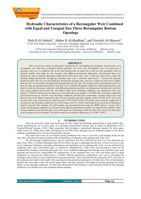
Hydraulic Characteristics of a Rectangular Weir Combined<br />
with Equal and Unequal Size Three Rectangular Bottom<br />
Openings<br />
Rafa H.Al-Suhaili 1 , Jabbar H.Al-Baidhani 2 , and NassrinJ.Al-Mansori 3<br />
1 Prof. Civil Engineering Dept., University of Baghdad, Baghdad, Iraq. Visiting Prof. at City College<br />
of New York, New York, USA.<br />
2 Prof. Environmental Engineering Dept., University of Babylon, Babylon, Iraq.<br />
3 Assistant Lecturer, Environmental Engineering Dept., University of Babylon, Babylon, Iraq.<br />
ABSTRACT<br />
This research was based on laboratory experiments for investigating the hydraulic characteristics of a<br />
rectangular weir with three rectangular bottom openings. Two cases were investigated ,case A of equal size of<br />
openings, and case B of different size of the mid opening than an equal size of the two side openings(. Fifty-six<br />
physical models were made for this structure with different geometrical dimensions. Experimental data were<br />
analyzed in order to find the discharge coefficient for three flow cases. Case 1 when the water level is under the<br />
openings height (partial flow through the openings only), case 2 when the water level is between the openings<br />
height and under the weir crest level (full flow through the openings only), and case 3 when the water level is higher<br />
than the weir crest level (flow through both openings and over the weir). The analysis of the experimental results was<br />
done by using an equation prepared for each flow case, to find the discharge coefficients. Dimensional analysis was<br />
made to relate the discharge coefficient with different geometrical and flow non dimensional variables for each flow<br />
case, using Artificial neural networks. The highest value of the discharge coefficient, was obtained for flow case<br />
number 3, (0.6188, while its lowest value was occurred for flow case number 1,( 0.0288).The correlation coefficients<br />
found between each of the flow cases discharge coefficient, and the ratio of individual opening width to the total<br />
head (b o /H) are the highest among the other relevant variables and have negative values (-0.942,-0.937,-0.871) for<br />
the three flow cases respectively for equal size and (-0.953,-0.941,-0.503. For all the cases tested the coefficients of<br />
variation for the discharge coefficient were in the range of (0.211 - 0.563) which indicate the necessity of obtaining a<br />
model to describe this variation. Six ANN models were developed herein using the (SPSS software, version 19) to<br />
express the discharge coefficient as a function of the different geometrical and flow non dimensional variables. Three<br />
of these models are for the three flow cases with equal size of openings, while the other three are for the three flow<br />
case for unequal size of openings. The models range of correlation coefficients is (r=0.999 - 0.997).<br />
I. INTRODUCTION<br />
Gates and weirs have been used extensively for flow control and discharge measurement in open channel flow.<br />
Works concerning the use of sluice gates as a discharge measurement structure may be found in, Rajaratnam (1977),<br />
French(1986),and Swamee (1992). Many researchers had developed a generalized discharge equation for sluice gates,<br />
Abdel-Azim et al. (2002), Bos (1989), and Munson et al.(1994). Weirs and gates may be combined together in one device<br />
yielding a simultaneous flow over the weir and below the gate.<br />
The reason lead to the use of a bottom opening combined with weirs is to provide a self-cleaning facility for the<br />
weir. This will reduce the typical problem of the accumulation of sediments at the upstream side of the weir.<br />
The flow through combined devices may be classified as free flow when both the flow over weir and below the<br />
gate is free, while it is termed submerged when the flow below the gate is submerged and the flow over the weir may or may<br />
not be submerged. Problems concerning sedimentation and depositions in the upstream side of the weir are minimized by<br />
combining these weirs with bottom gates as outlined by Alhamid(1997). Fadil (1997) had developed a meter for the<br />
combined flow through a contracted sluice gate and a weir. Combined-submerged flow through weirs and below gates were<br />
analyzed and discussed by Negm(2000).The characteristics of the combined flow over weirs and below gates of equal<br />
contraction are discussed by Abdel-Azim et al.(2002), different geometrical combinations were used to investigate the<br />
discharge characteristics of such combined weirs and gate structures. They found that the flow parameter (H/D ) (the ratio of<br />
the upstream water depth to the height of the opening) and the geometrical parameter (y/D) (the ratio of the vertical distance<br />
between the lower edge of the weir and the upper edge of the gate opening to the height of the gate opening) have major<br />
effects on the discharge coefficient. Al-Suhili and Shwana(2013) had obtained a neural networks model for the discharge<br />
coefficient of a Cipoletti weir with rectangular bottom opening.<br />
|| Issn 2250-3005 (online) || || January || 2014 || Page 13
Hydraulic Characteristics of a Rectangular Weir Combined with Equal and Unequal Size Three…<br />
All of the above cited researches concerning weirs combined with only one bottom opening located at<br />
the middle of the weir section. This is expected to help removing sediments accumulated at the upstream side<br />
from the mid-section only, keeping the accumulated sediments at both sides. Al-Suhili et al. (2013) had obtained<br />
ANN models for a rectangular weir with three equal sized bottom openings. The use of three bottom openings,<br />
one at the middle of the section and one in each side will enhance the self-cleaning efficiency of the weir. This<br />
will definitely remove the accumulated sediments from the whole section rather than from the mid-section only<br />
removed by providing one mid bottom opening. The characteristics of the combined flow over a rectangular<br />
weir with three equal sized and unequal sized rectangular bottom openings are experimentally investigated. The<br />
aim of this research is to develop models for estimating the discharge coefficients of such structure for the three<br />
flow cases expected, case one the partial flow through the openings only, case two the full flow through the<br />
openings only, and case 3 the combined flow through the openings and over the weir simultaneously, for both<br />
equal sized and unequal sized openings.<br />
Theoretical background<br />
To compute the discharge through a combined rectangular weir with three rectangular bottom openings<br />
an experimental work has been done, as mentioned above. Fifty six weir models were constructed and tested<br />
with different geometrical dimensions of the opening and weir. Each model is designated as configuration<br />
hereafter, as shown in table(1). The details of the experimental work will be explained later. First of all the<br />
derivation of the equations that describes the flow relationship for each flow case is presented as follows:<br />
CASE A: Three equal sized bottom openings:<br />
For this case three flow cases equations were developed as follows:<br />
Flow case no. (1)<br />
This flow case is the partial flow from the bottom openings only, which occurs when the water level in the<br />
flume is less than the height of the openings, and it's flow is designated as Q p . To compute the discharge through<br />
the three bottoms rectangular openings of this flow condition consider first,<br />
Q pt eo = 2 3 . b o 2g. H 3 2 1<br />
Q ptot = 3 Q pt eo (2)<br />
Where: Q ptheo is the theoretical partial discharge through one opening Q totm 3 /s); Q ptot is the total<br />
theoretical partial discharge through the three openings ; H is the total head (m), b o is the opening width (m), g is<br />
the gravitational acceleration (m/s 2 ). But the actual discharge for the opening is Q pacto which can be written as:<br />
Q pacto =Cd p1 . Q ptheo (3)<br />
Where: Cd p1 is the discharge coefficient for one opening.<br />
For the flow condition of three openings, the actual flow is:<br />
Q pactot =Cd p . Q ptot (4)<br />
Where: Cd p is the discharge coefficient for three openings.<br />
Flow case No. (2)<br />
This flow case is the full flow from the openings only, which occurs when the water level in the flume<br />
is more than the height of the openings and less than the height of the weir crest, and it's flow is designated as,<br />
Q f , . The difference between this flow case and flow case 1 is the area of flow which is here (b o x h o ) the width<br />
and height of the opening rather than (b o x H). However the same equations of flow case 1 can be used for this<br />
flow case, where the error can be accounted for by the discharge coefficient of this flow case.<br />
Q fact = Cd f . Q ptot (5)<br />
Where: Cd f is the discharge coefficient for the three openings.<br />
Flow case No. (3)<br />
This flow case is the combined full flow from the openings and that over the weir, that occurs when the<br />
water level in the flume is higher than the weir crest level, and it's flow is designated as, Q c . For this flow case,<br />
|| Issn 2250-3005 (online) || || January || 2014 || Page 14
Hydraulic Characteristics of a Rectangular Weir Combined with Equal and Unequal Size Three…<br />
the following equation can be obtained by adding the discharge over the weir and the discharge through three<br />
openings as follows:<br />
Q ctheo = Q f tot + Q wtheo (6)<br />
Q fteo = 2 3 . b o 2g. [(P + 1) − P + 1 − o ] 3 2 (7)<br />
Which, can be approximated by:<br />
Q fteo = b o . o 2gH (8)<br />
Q ftot = 3 Q fteo (9)<br />
Q wtheo = (2/3) (2g) 0.5 (h1) (2/3) = 2 3 . B w 2g 1<br />
3<br />
2<br />
(10)<br />
Where: Q ftot is the total discharge through the openings same as mentioned before but with H=P+h 1<br />
;Q wtheo is the theoretical discharge over the rectangular weir; H is the total head (m); b o is the opening width (m);<br />
h o is the opening; height (m), g is the gravitational acceleration (m/s 2 ); P is the crest height (m),P=d+ h o ;B w is<br />
the width of the weir(m)and h 1 is the head over the rectangular weir crest (m). But the actual discharge are: Q fact ,<br />
Q wact for the openings and the weir respectively.<br />
Q f act =Cd f . Qf tot (11)<br />
Q w act =Cd w .Qw theo (12)<br />
Q c. act =Q f act + Qw act. (13)<br />
Where: Cd f and Cd w are the discharge coefficients for the openings and the weir respectively. Then by<br />
substituting equations (11 and 12) into equation (13) yield s:<br />
Q c.act = C dc . 2g[ 3(b o . o H) + ( 2 3 B w 1<br />
3<br />
2<br />
)] (14)<br />
Where: C dc C dc is the discharge coefficient for the combined flow.<br />
CASE B: Three unequal Size bottom openings:<br />
For this case similar equations could be obtained as in case A above for each flow case, but with<br />
the modification for the flow area through the three openings, for example equation (2) will be:<br />
Q ptot = Q pt eom + 2 Q pt eos (15)<br />
Where, Q ptheom is the flow through the mid opening with area of (b o x H), and Q ptheos is the flow from either the left<br />
or right opening with area (b L x H) or(b R x H) since the left and right openings are equal in size , where b o ,b L , and b R are the<br />
width of the mid, left and right opening respectively. Similar modifications were made for the equations of the flow cases 2<br />
and 3.<br />
Experimental Setup:<br />
The experiments were carried out in a (17) m long horizontal channel (slope equal zero) of cross section (0.5) m<br />
width and (0. 5) m height. The flume channel is fabricated from glass walls and a stainless steel floor. Two movable<br />
carriages with point gauges were mounted on a brass rails at the top of channel sides see Figure (1).Fifty -six combined weirs<br />
models were manufactured from a 10mm thickness glass, the configurations details of these models are shown in table (1)<br />
and figure(2). For discharge measurements, a full width thin-plate sharp-crested rectangular weir was fixed at the tail end of<br />
the flume channel section manufactured according to the British standards (1965). The head upstream of the standard weir<br />
and head over the combined weir were measured with a precise point gauges whose least count was (0.1) mm.<br />
Dimensional analysis for Discharge Coefficient<br />
It is expected that the discharge coefficient of the three types of flow conditions mentioned above are<br />
dependent on the geometry of the models as well as on the flow conditions, i.e.<br />
|| Issn 2250-3005 (online) || || January || 2014 || Page 15
Hydraulic Characteristics of a Rectangular Weir Combined with Equal and Unequal Size Three…<br />
Cd=f ( h L ,b L ,h M , b M ,h R , b R , d ,H w , B w , h 1 ,H, v ,g, ρ , µ ,S o ,σ, B) (16)<br />
Where:<br />
h L : is the height of left bottom opening<br />
b L : is the width of left bottom opening<br />
h M : is the height of middle bottom opening<br />
b M : is the width of middle bottom opening,<br />
h R : is the height of right bottom opening<br />
b R : is the width of right bottom opening,<br />
d: is the vertical distance between the top of the opening and bottom of weir (weir crest)<br />
H w : is the vertical distance between weir crest and top of the weir.<br />
B w : is the width of the weir,<br />
h 1 : is the head measured over the weir for flow case no.(3),<br />
H: is the total head measured for each flow case,<br />
v: is the flow velocity.<br />
g: is the gravitational acceleration.<br />
ρ: is the water mass density.<br />
µ: is the water viscosity.<br />
S o : is the flume slope.<br />
σ: is the surface tension, and<br />
B: is the flume width.<br />
It should be noted that the flume bed slope and the flume width were kept constant. As well as v can be<br />
represented by the variable H. Then, the discharge coefficient will be for case B:<br />
<br />
<br />
as:<br />
Flow case No.(1)<br />
The functional relationship which describes the discharge coefficient for this flow case may be written as:<br />
Cd p =F 1 (h L /H ,b L /H , h M /H ,b M /H ,h R /H ,b R /H ) (17)<br />
Flow case No.(2)<br />
The functional relationship which describes the discharge coefficient for this flow case may be written<br />
Cd f = F 2 (h L /H ,b L /H , h M /H ,b M /H ,h R /H ,b R /H,d/H ) (18)<br />
Flow case no. (3)<br />
The functional relationship, which describes the discharge coefficient for this flow case can be written<br />
as:<br />
Cd c =F 3 (h L /H ,b L /H , h M /H ,b M /H ,h R /H ,b R /H,d/H ,H w /H,B w /H) (19)<br />
Statistical analysis of the experimental results<br />
The experimental results obtained were classified according to the two cases A and B, where as<br />
mentioned above the first one is that when the dimensions of three openings are equal, while the second one<br />
when the dimension of the mid opening is different than the equal dimensions of the two sides openings.<br />
Equations (17,18 and 19) are general and can be used for case B. For Case A these equation can be reduced as<br />
follows:<br />
a. Flow case no. (1): Cd p =F 1 (h o /H ,b o /H ) (20)<br />
b. Flow case no.(2): Cd f =F 2 (h o /H, b o /H ,d/H ) (21)<br />
c. Flow case no.(3): Cd c =F 3 (h 1 /H, h o /H, b o /H, d/H, H w /H, B w /H ) (22)<br />
Tables (2,3 and 4) show the descriptive statics and the correlation analysis for each flow case for this case<br />
of equal size openings( case A). In all of these tables, it is shown that the highest correlations of the three<br />
discharge coefficients are with b o /H and have negative values, which indicates that the discharge coefficients<br />
|| Issn 2250-3005 (online) || || January || 2014 || Page 16
Hydraulic Characteristics of a Rectangular Weir Combined with Equal and Unequal Size Three…<br />
are inversely proportional with this variable and that this variable has the highest effect on the value of these<br />
discharge coefficients among the other relevant variables.<br />
Tables (5,6 and 7) show the descriptive statistics and the correlation analysis for each flow case for the<br />
second case of different mid opening size than the two sides openings( Case B). In all these tables, same<br />
observation as in the first case was found that is the highest correlations of these discharge coefficients are with<br />
b o /H and have negative values.<br />
Results and discussion:<br />
Case A: Equal sized openings:<br />
The variation of (Cd p, Cd f ,Cd c) for this case, with each of the variables (h o /H, b o /H , d/H,h 1 /H,<br />
H w /H,B w /H,) are shown in Figures (3 to 8), respectively . Even though these Figures indicate high scattering<br />
which means single correlation between the Cd and each variable is low, it is expected that multiple correlation<br />
for Cd with these variables will be significant. Figure (3) shows the variation of discharge coefficients for the<br />
flow cases (Cd p, Cd f ,Cd c ), with the value of (h o /H) ratio. It is clear that the maximum discharge coefficient is less<br />
than 0.6188 and this means that the maximum correction that accounts for the assumptions of the theoretical<br />
discharge equation is 38 % .Moreover it is found that the discharge coefficient decreases as (h o /H) increases.<br />
Flow case no. (1), gives the lowest discharge coefficient followed by flow case no. (2), and finally flow case no.<br />
(3). This may be attributed to the increase of losses as the head increased. Figure (4) shows the variation of the<br />
discharge coefficients for the three flow cases (Cd p, Cd f ,Cd c ), with the values of (b o /H) ratio. Similar<br />
observations are found as these observed in Figure (3), however, the relation exhibits less fluctuated results.<br />
Figure (5) shows that in general the discharge coefficients for the flow cases (Cd f ,Cd c ),decreases when(d/H)<br />
value increase. The presented values are not for fixed (d value) and variable (H) value but both are varied. For<br />
the combined discharge, the variations are much higher than for Cd f (flow case no.2). For a given (d/H) value,<br />
different discharge coefficient can be obtained and that is indicates the effect of the other relevant<br />
variables.Similarly, the variations of the three discharge coefficients with (h 1 /H), (H w /H) and (B w /H) are shown<br />
in Figures (6), (7) and (8) respectively. These Figures indicate proportional variation of the first variable and<br />
inverse proportional variation for the other two variables .However, for each unique value of the variables<br />
different discharge coefficient values can be obtained which indicate the combined effects of the other relevant<br />
variables.<br />
Case B: Unequal sized openings:<br />
The variation of (Cd p, Cd f ,Cd c) for this with each of the variables (h o /H, b o /H ,b M /H,d/H, H w /H,B w /H,)<br />
are shown in Figures (9 to 14), respectively . Even though these Figures indicate high scattering which means<br />
single correlation between the Cd and each variable is low, it is expected that multiple correlation for Cd with<br />
these variables will be significant. The general observations found for this case are almost similar to those<br />
observed for case A. The variations of the three discharge coefficients with any single variable had shown<br />
considerable scattering, which reflects the effect of the other variables.<br />
The observations obtained for the two cases indicates the necessity of relating the discharge<br />
coefficients with all of the variables using a multivariate model , such as multiple regression or artificial neural<br />
networks. The artificial neural networks model had proved recently its effectiveness, hence used herein for the<br />
modeling process.<br />
Artificial neural networks modeling for the discharge coefficient<br />
The artificial neural network (ANN), is a mathematical model or computational model that is inspired<br />
by the structure and/or functional aspects of the biological neural networks. A neural network consists of an<br />
interconnected group of artificial neurons, and it processes information using a connectionist approach to<br />
computation. Six artificial neural network models were developed for estimating the discharge coefficients (Cd p<br />
,Cd f ,Cd c ) as a function of the variables listed in equations (17 to 22). These models are classified according to<br />
the cases A and B and for each according to the flow case. These model were developed using the software<br />
"SPSS,version 19", this software allows the modeling with different network architecture, and use back<br />
propagation algorithm for adjusting the weights of the model. The software needs to identify the input variables<br />
which are those mentioned above as shown in Figures (9, 10,11,12,13 and 14) respectively.<br />
CONCLUSIONS<br />
Under the limitations imposed in this study, the following conclusions are obtained:<br />
|| Issn 2250-3005 (online) || || January || 2014 || Page 17
Hydraulic Characteristics of a Rectangular Weir Combined with Equal and Unequal Size Three…<br />
1. All the flow conditions proposed exhibits sub critical flow at the upstream side of the structure, since<br />
Froude number range is less than (1).<br />
2. For each model, with specific dimensions, as the head increased, the discharge coefficients for all<br />
three flow cases were increased. The highest value of the discharge coefficient, was obtained for flow case no.3,<br />
(Cd c = 0.6188), while the lowest value of discharge coefficient was obtained for flow case no.1,(Cd p =0.0288).<br />
3. For the case of equal size of the three openings and for flow case no.(3) ,the discharge coefficient<br />
Cd c has the highest value for a size of opening of (5*10)cm, while the lowest value is for the size (10*10).This<br />
indicates that the width of opening has the major effect on the values of Cd c .<br />
4. Correlation analysis for all of the three flow cases between the discharge coefficients and the<br />
variables involved, indicates that (Cd p ) , (Cd f ) ,(Cd c ) have the highest correlation with (b o /H) with negative<br />
values of (-0.942,-0.937,-0.871) respectively for equal sizss and that for unequal sizes(-0.953,-0.941,-0.503).<br />
These negative values indicate inverse proportionality.<br />
5. For all the cases tested the coefficient of variation for the discharge coefficient were in the range of<br />
(0.6263 - 0.1643) for all of the three flow cases, which indicate the necessity of obtaining a model to describe<br />
this variation.<br />
6. The architecture of the three developed ANN models and the selected parameters and activation<br />
functions shown in the related figures and tables are suitable for relating the discharge coefficient with the<br />
geometry and the flow variables .The networks correlation coefficients between the observed and predicted<br />
discharge coefficients were in the range of (0.999- 0.997), which can be considered as a very good correlation.<br />
REFERENCES<br />
[1.] Abdel-Azim A.M.,(2002) ,"Combined of Free Flow Over Weirs and Below Gates ", Journal of<br />
Hydraulic Research, vol.40,no.3.<br />
[2.] Alhamid A.A., NegmA.M. and Al-Brahim A.M.,(1997),"Discharge Equation for Proposed Self-<br />
Cleaning Device", Journal of King Saud University, Engineering ,Science, Riyadh, Saudia<br />
Arabia,vol.9,no.1, pp.13-24.<br />
[3.] Al- Suhili R.H. and Shwana A. J., (2013), "Prediction of the Discharge Coefficient for a Cipolletti Weir<br />
with Rectangular Bottom Opening", submitted to journal of flow control and visualization, for<br />
publication.<br />
[4.] Al-Suhili R.H., Al-Baidhani J. H., and Al-Mansori N. J. , (2013),"Hydraulic characteristics of flow over<br />
Rectangular weir with three EqualSize Rectangular bottom openings using ANN", accepted for<br />
publication, Journal of Babylon university, Iraq.<br />
[5.] Bos M.G.,(1989),"Discharge Measurement Structure” 3 rd ed.,Int. Confer. for Land Reclamation and<br />
Improvement, Wageningen, the Netherlands.<br />
[6.] British Standard Institution (BSI);(1965);"Thin-Plate Weirs and Venturi Flumes in Methods of<br />
Measurement of Liquid Flow In Open Channel”,Part4A,BSI,3681,BSI,London.<br />
[7.] FadilH.A.,(1997) ,"Development of a Meter for the Combined Flow Through Contracted Slice Gate and<br />
Weir",Almuktar Science journal,No.4,University of Omar Almuktar ,Beida,Libya.<br />
[8.] French,R.H.,(1986),"Open Channel Hydraulic", pp.343-353,McGraw Hill Book Co., New York.<br />
[9.] Munson B.R.,YoungD.F. and OkllshiT.H.,(1994) ,"Fundamental of Fluid Mechanics", 2nd ed., John<br />
Wiley and Sons,Inc.,New Yourk.<br />
[10.] NegmA.M.,(2000), "Characteristics of Simultaneous Over Flow- Submerged Under Flow (Unequal<br />
Contraction) ", Engineering, Bulletin, Faculty of Engineering,AinShams<br />
University,vol.35,no.1,March,pp.137-154.<br />
[11.] RajaratnamN.(1977),"Free Flow Immediately Below Sluice Gates", Proceeding ,ASCE, Journal of<br />
Hydraulic Engineering Division, 103,No.HY4,pp.345-351.<br />
[12.] Swamee P.K.,(1992),"Sluice-Gate Discharge Equation", Proceeding ,ASCE, Journal, Irrigation and<br />
Drainage Engineering Division, vol.,93, no.IR3,pp.167-186<br />
|| Issn 2250-3005 (online) || || January || 2014 || Page 18
Hydraulic Characteristics of a Rectangular Weir Combined with Equal and Unequal Size Three…<br />
Models<br />
1.a 1<br />
1<br />
1<br />
1<br />
1<br />
1<br />
1<br />
1.b 1<br />
1<br />
1<br />
1<br />
1<br />
1<br />
1<br />
2.a 2<br />
2<br />
2<br />
2<br />
2<br />
2<br />
2<br />
2.b 2<br />
2<br />
2<br />
2<br />
2<br />
2<br />
2<br />
2.c 2<br />
2<br />
2<br />
2<br />
2<br />
2<br />
2<br />
3.a 3<br />
3<br />
.a.1<br />
.a.2<br />
.a.3<br />
.a.4<br />
.a.5<br />
.a.6<br />
.a.7<br />
.b.1<br />
.b.2<br />
.b.3<br />
.b.4<br />
.b.5<br />
.b.6<br />
.b.7<br />
.a.1<br />
.a.2<br />
.a.3<br />
.a.4<br />
.a.5<br />
.a.6<br />
.a.7<br />
.b.1<br />
.b.2<br />
.b.3<br />
.b.4<br />
.b.5<br />
.b.6<br />
.b.7<br />
.c.1<br />
.c.2<br />
.c.3<br />
.c.4<br />
.c.5<br />
.c.6<br />
.c.7<br />
.a.1<br />
.a.2<br />
Crest<br />
height<br />
(P=h o+d)<br />
cm<br />
Table (1) Details of the weir models investigated.<br />
Crest<br />
length (B w)<br />
cm<br />
Bottom Openings<br />
(b o x h o) cm<br />
Left middle Right<br />
28 20 5*10 5*10 5*10<br />
10*10 10*10 10*10<br />
10*5 10*5 10*5<br />
10*8 10*8 10*8<br />
8*8 8*8 8*8<br />
8*10 10*10 8*10<br />
5*8 8*8 5*8<br />
28 27 5*10 5*10 5*10<br />
10*10 10*10 10*10<br />
10*5 10*5 10*5<br />
10*8 10*8 10*8<br />
8*8 8*8 8*8<br />
8*10 10*10 8*10<br />
5*8 8*8 5*8<br />
24 33 5*10 5*10 5*10<br />
10*10 10*10 10*10<br />
10*5 10*5 10*5<br />
10*8 10*8 10*8<br />
8*8 8*8 8*8<br />
8*10 10*10 8*10<br />
5*8 8*8 5*8<br />
24 25 5*10 5*10 5*10<br />
10*10 10*10 10*10<br />
10*5 10*5 10*5<br />
10*8 10*8 10*8<br />
8*8 8*8 8*8<br />
8*10 10*10 8*10<br />
5*8 8*8 5*8<br />
24 17 5*10 5*10 5*10<br />
10*10 10*10 10*10<br />
10*5 10*5 10*5<br />
10*8 10*8 10*8<br />
8*8 8*8 8*8<br />
8*10 10*10 8*10<br />
5*8 8*8 5*8<br />
20 23 5*10 5*10 5*10<br />
10*10 10*10 10*10<br />
|| Issn 2250-3005 (online) || || January || 2014 || Page 19
Hydraulic Characteristics of a Rectangular Weir Combined with Equal and Unequal Size Three…<br />
3<br />
3<br />
3<br />
3<br />
.a.3<br />
.a.4<br />
.a.5<br />
.a.6<br />
10*5 10*5 10*5<br />
10*8 10*8 10*8<br />
8*8 8*8 8*8<br />
8*10 10*10 8*10<br />
Models<br />
Cre<br />
st height<br />
(P=<br />
h o +d) cm<br />
Table (1) continued<br />
Crest<br />
length (B w )<br />
Cm<br />
Bottom Openings<br />
(b o x h o ) cm<br />
left Middle right<br />
3.a 3<br />
3.b 3<br />
3<br />
3<br />
3<br />
3<br />
3<br />
3<br />
3.c 3<br />
3<br />
3<br />
3<br />
3<br />
3<br />
3<br />
.a.7<br />
.b.1<br />
.b.2<br />
.b.3<br />
.b.4<br />
.b.5<br />
.b.6<br />
.b.7<br />
.c.1<br />
.c.2<br />
.c.3<br />
.c.4<br />
.c.5<br />
.c.6<br />
.c.7<br />
20 23 5*8 8*8 5*8<br />
20 18 5*10 5*10 5*10<br />
10*10 10*10 10*10<br />
10*5 10*5 10*5<br />
10*8 10*8 10*8<br />
8*8 8*8 8*8<br />
8*10 10*10 8*10<br />
5*8 8*8 5*8<br />
20 15 5*10 5*10 5*10<br />
10*10 10*10 10*10<br />
10*5 10*5 10*5<br />
10*8 10*8 10*8<br />
8*8 8*8 8*8<br />
8*10 10*10 8*10<br />
5*8 8*8 5*8<br />
|| Issn 2250-3005 (online) || || January || 2014 || Page 20
Hydraulic Characteristics of a Rectangular Weir Combined with Equal and Unequal Size Three…<br />
Table (2) Descriptive statistics and correlation analysis for flow case1 of equal size openings.<br />
Corr<br />
elation with<br />
Cd p Min. Max. Mean<br />
Coefficie<br />
Std. nt of variance C.V<br />
Deviation<br />
Cd p 1 .0288 0.2464 0.08038 0.045 0.563<br />
h o /H -<br />
0.484<br />
b o /H -<br />
0.871<br />
.3137 2.8571 1.47319 .4609 0.312<br />
.3922 3.3333 1.47433 .5708 0.387<br />
Table (3) Descriptive statistics and correlation analysis for flow case.2 of equal size openings.<br />
Correl<br />
ation<br />
with<br />
Cdf<br />
Min.<br />
Max<br />
St<br />
. Mean d. Deviation<br />
Cdf 1 .1118 .463 .219 .0<br />
783<br />
h o /H -0.151 .2083 .862 .473 .1<br />
503488<br />
d/H -0.5 .5051 1.66 .931 .3<br />
140890<br />
b o /H -0.937 .2083 .862 .508 .1<br />
485248<br />
Coefficient of<br />
variance C.V<br />
0.3560<br />
0.3174<br />
0.3370<br />
0.2919<br />
Table (4) Descriptive statistics and correlation analysis for flow case.3 of equal size openings.<br />
Correl<br />
ation with Cdc<br />
Min.<br />
Max<br />
. Mean<br />
Std.<br />
Deviation<br />
Coefficient of<br />
variance<br />
C.V<br />
Cdc 1 .1233 .618 .3343 .109 0.3279<br />
h 1 /H -0.035 .0019 1.00 .1905<br />
4<br />
h o /H 0.122 .1220 .512 .2962<br />
88<br />
d/H -0.374 .2825 .804 .5180<br />
42<br />
h w /H -0.384 .2927 1.02 .6041<br />
75<br />
b w /H -0.222 .4237 1.17 .7513<br />
41<br />
b o /H -0.942 .1333 .497 .2772<br />
49<br />
.130 0.6263<br />
.080 0.2718<br />
.099 0.1927<br />
.185 0.3066<br />
.180 0.2399<br />
.091 0.3306<br />
|| Issn 2250-3005 (online) || || January || 2014 || Page 21
Hydraulic Characteristics of a Rectangular Weir Combined with Equal and Unequal Size Three…<br />
Table (5) Description of statistical and correlation analysis for flowcase.1 of unequal size<br />
openings.<br />
Corr<br />
elation with<br />
Cdp Min. Max. Mean<br />
Cd p 1 .0512 .1299 .0797<br />
89<br />
ho/<br />
H<br />
bo/<br />
H<br />
bm<br />
/H<br />
-<br />
0.829<br />
-<br />
0.953<br />
-<br />
0.891<br />
.9877 2.6316 1.568<br />
840<br />
.6173 1.6667 1.149<br />
196<br />
.9877 2.5000 1.546<br />
481<br />
Std.<br />
Deviation<br />
0.02<br />
2147<br />
.361<br />
8480<br />
.282<br />
9684<br />
.340<br />
0340<br />
Coefficient<br />
of variance C.V<br />
0.278<br />
0.230<br />
0.2462<br />
0.2199<br />
Table (6) Description of statistical and correlation analysis for flowcase.2 of unequal size openings.<br />
Corr<br />
elation with<br />
Cdf Min. Max. Mean<br />
Cdf 1 .1535 .4349 .257371 .0<br />
544150<br />
ho/H -<br />
0.863<br />
d/H -<br />
0.267<br />
bo/H -<br />
0.941<br />
bm/<br />
H<br />
-<br />
0.913<br />
.2963 .7246 .486850 .0<br />
935586<br />
.4184 1.4493 .785755 .2<br />
758444<br />
.1852 .5797 .347372 .0<br />
870414<br />
.2963 .7246 .481407 .0<br />
879130<br />
Coefficient<br />
St of variance C.V<br />
d. Deviation<br />
0.211<br />
0.192<br />
0.351<br />
0.2505<br />
0.182<br />
Table (7) Description of statistical and correlation analysis for flowcase.3 of unequal size openings<br />
Corr<br />
elation<br />
with<br />
Cdc Min. Max. Mean<br />
Cdc 1 .2291 .5200 .37248<br />
9<br />
h 1 /H 0.318 .0100 .4123 .17998<br />
9<br />
ho/H -<br />
0.462<br />
d/H -<br />
0.015<br />
Hw/<br />
H<br />
Bw/<br />
H<br />
-<br />
0.242<br />
-<br />
0.240<br />
bo/H -<br />
0.503<br />
bm/<br />
H<br />
-<br />
0.489<br />
.2145 .4854 .31712<br />
0<br />
.3343 .6667 .49295<br />
2<br />
.3217 .9950 .60821<br />
5<br />
.4310 1.1744 .74596<br />
5<br />
.1340 .3883 .22424<br />
0<br />
.2145 .4854 .31467<br />
7<br />
Std.<br />
Deviation<br />
.082<br />
3017<br />
.090<br />
8628<br />
.067<br />
3664<br />
.081<br />
0564<br />
.191<br />
3325<br />
.170<br />
9562<br />
.072<br />
1830<br />
.068<br />
9368<br />
Coeffi<br />
cient of<br />
variance C.V<br />
0.221<br />
0.504<br />
0.2122<br />
0.1643<br />
0.3145<br />
0.229<br />
0.3219<br />
0.219<br />
|| Issn 2250-3005 (online) || || January || 2014 || Page 22
4<br />
00mm<br />
Hydraulic Characteristics of a Rectangular Weir Combined with Equal and Unequal Size Three…<br />
Figure(1)Experimental setup used.<br />
H<br />
d<br />
p<br />
h<br />
w<br />
o<br />
B<br />
w<br />
b L b m b R<br />
500 mm<br />
Figure (2) the physical model section of the proposed weir.<br />
|| Issn 2250-3005 (online) || || January || 2014 || Page 23
Cdp,Cdf,Cdc<br />
Cdf, Cdc<br />
Cdp,Cdf,Cdc<br />
Hydraulic Characteristics of a Rectangular Weir Combined with Equal and Unequal Size Three…<br />
0.5<br />
0.45<br />
0.4<br />
0.35<br />
0.3<br />
0.25<br />
0.2<br />
0.15<br />
0.1<br />
0.05<br />
0<br />
0 1 2 3<br />
h o /H<br />
Cdp Cdf Cdc<br />
Figure (3) Variation of the three discharge coefficients with (h o /H), for equal sizes of openings(CASE A).<br />
0.5<br />
0.4<br />
0.3<br />
0.2<br />
0.1<br />
0<br />
0 0.5 1 1.5 2 2.5 3 3.5<br />
b o /H<br />
Cdp Cdf Cdc<br />
Figure (4) Variation of the three discharge coefficients with (b o /H), for equal sizes of openings (CASE A).<br />
0.5<br />
0.4<br />
0.3<br />
0.2<br />
0.1<br />
0<br />
d/H<br />
Cdf Cdc<br />
0 0.5 1 1.5 2<br />
Figure (5) Variation of the full opening flow and combined flow discharge coefficients with (d/H) for<br />
equal sizes of openings (CASE A).<br />
|| Issn 2250-3005 (online) || || January || 2014 || Page 24
Cdc<br />
Cdc<br />
Cdc<br />
Hydraulic Characteristics of a Rectangular Weir Combined with Equal and Unequal Size Three…<br />
0.5<br />
0.45<br />
0.4<br />
0.35<br />
0.3<br />
0.25<br />
0.2<br />
0.15<br />
0.1<br />
0.05<br />
0<br />
0 0.1 0.2 0.3 0.4 0.5<br />
h 1 /H<br />
Figure (6) Variation of the combined flow discharge coefficient with (h 1 /H) for equal sizes of<br />
openings(CASE A).<br />
0.5<br />
0.45<br />
0.4<br />
0.35<br />
0.3<br />
0.25<br />
0.2<br />
0.15<br />
0.1<br />
0.05<br />
0<br />
0 0.2 0.4 0.6 0.8 1 1.2<br />
H w /H<br />
Figure (7) Variation of the combined flow discharge coefficient with (H w /H) for equal sizes of openings<br />
(CASE A).<br />
0.5<br />
0.4<br />
0.3<br />
0.2<br />
0.1<br />
0<br />
0 0.2 0.4 0.6 0.8 1 1.2 1.4<br />
B w /H<br />
Figure (8) Variation of the combined flow discharge coefficient with (Bw/H) for equal sizes of openings<br />
(CASE A).<br />
|| Issn 2250-3005 (online) || || January || 2014 || Page 25
Cdp,Cdf,Cdc<br />
Cdop,Cdof,Cdc<br />
Cdp, Cdf, Cdc<br />
Hydraulic Characteristics of a Rectangular Weir Combined with Equal and Unequal Size Three…<br />
0.5<br />
0.4<br />
0.3<br />
0.2<br />
0.1<br />
0<br />
0 0.5 1 1.5 2 2.5 3<br />
h o /H<br />
Cdp Cdf Cdc<br />
Figure (9) Variation of the three discharge coefficients with (h o /H) for different sizes of openings(CASE B).<br />
0.5<br />
0.4<br />
0.3<br />
0.2<br />
0.1<br />
0<br />
b o /H<br />
Cdp Cdf Cdc<br />
0 0.5 1 1.5 2<br />
Figure (10) Variation of the three discharge coefficients with (b o/H) for different sizes of openings(CASE B).<br />
0.5<br />
0.4<br />
0.3<br />
0.2<br />
0.1<br />
0<br />
0 0.5 1 1.5 2 2.5 3<br />
b m /H<br />
Cdp Cdf Cdc<br />
Figure (11) Variation of the three discharge coefficients with (b m/H) for different sizes of openings(CASE B).<br />
|| Issn 2250-3005 (online) || || January || 2014 || Page 26
Cdc<br />
Cdc<br />
Cdf, Cdc<br />
Hydraulic Characteristics of a Rectangular Weir Combined with Equal and Unequal Size Three…<br />
0.5<br />
0.45<br />
0.4<br />
0.35<br />
0.3<br />
0.25<br />
0.2<br />
0.15<br />
0.1<br />
0.05<br />
0<br />
0 0.5 1 1.5 2<br />
d/H<br />
Cdof<br />
Figure (12) Variation of the full openings flow and combined flow discharge coefficients with (d/H) for different<br />
sizes of openings(CASE B).<br />
0.5<br />
0.45<br />
0.4<br />
0.35<br />
0.3<br />
0.25<br />
0.2<br />
0.15<br />
0.1<br />
0.05<br />
0<br />
Figure (13) Variation of the combined flow discharge coefficient with (H w/H) for different sizes of openings (CASE B).<br />
Cdc<br />
0 0.2 0.4 0.6 0.8 1 1.2<br />
H w /H<br />
0.5<br />
0.45<br />
0.4<br />
0.35<br />
0.3<br />
0.25<br />
0.2<br />
0.15<br />
0.1<br />
0.05<br />
0<br />
0 0.2 0.4 0.6 0.8 1 1.2 1.4<br />
B w /H<br />
Figure (14) Variation of the combined flow discharge coefficient with (B w/H) for different sizes of openings (CASE B).<br />
|| Issn 2250-3005 (online) || || January || 2014 || Page 27
Hydraulic Characteristics of a Rectangular Weir Combined with Equal and Unequal Size Three…<br />
Figure (15) The ANN model architecture for case A, flow case no.(1) (R=0.999).<br />
Figure (16) The ANN model architecture for case A, flow case no.(2) (R=0.999)<br />
Figure (17) The ANN model architecture for case A, flow case no.(3) (R=0.999).<br />
|| Issn 2250-3005 (online) || || January || 2014 || Page 28
Hydraulic Characteristics of a Rectangular Weir Combined with Equal and Unequal Size Three…<br />
Figure (18) The ANN model architecture for case B, flow case no.(1) (R=0.997)<br />
Figure (19) The ANN model architecture for case B, flow case no.(2) (R=0.998)<br />
Figure (20) The ANN model architecture for case A, flow case no.(3) (R=0.997)<br />
|| Issn 2250-3005 (online) || || January || 2014 || Page 29