Makita - SG1250 - Wall Chasing Machine
Makita - SG1250 - Wall Chasing Machine
Makita - SG1250 - Wall Chasing Machine

Create successful ePaper yourself
Turn your PDF publications into a flip-book with our unique Google optimized e-Paper software.
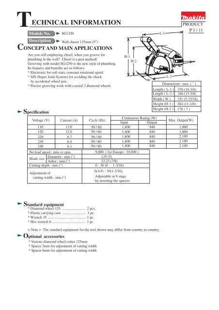
TECHNICAL INFORMATION<br />
Models No.<br />
Description<br />
CONCEPT AND MAIN APPLICATIONS<br />
Specification<br />
<strong>SG1250</strong><br />
<strong>Wall</strong> chaser 125mm (5")<br />
Are you still employing chisel, when you groove for<br />
plumbing in the wall? Chisel is a past method!<br />
Grooving with model <strong>SG1250</strong> is the new style of plumbing.<br />
Its features and benefits are as follows.<br />
* Electronic for soft start, constant rotational speed<br />
* SJS (Super Joint System) for avoiding the shock<br />
by accidental wheel jam.<br />
* Precise grooving work with coaxial 2 diamond wheels<br />
Voltage (V) Current (A) Cycle (Hz)<br />
Continuous Rating (W)<br />
Input<br />
Output<br />
110 13.0<br />
50 / 60<br />
1,400<br />
840<br />
120<br />
12.0<br />
50 / 60<br />
1,400<br />
840<br />
220<br />
6.7<br />
50 / 60<br />
1,400<br />
840<br />
230<br />
6.4<br />
50 / 60<br />
1,400<br />
840<br />
240<br />
6.1<br />
50 / 60<br />
1,400<br />
840<br />
No load speed : min-1= rpm.<br />
Blade size<br />
Diameter : mm (")<br />
Arbor : mm (")<br />
Cutting depth : mm (")<br />
Adjustment of<br />
cutting width : mm (")<br />
H-1<br />
H-2<br />
9,000 ( for Europe : 10,000 )<br />
125 (5)<br />
22.23 (7/8)<br />
0 - 30 (0 - 1-3/16)<br />
6(1/4) - 30(1-3/16)<br />
Adjustable in 9 stage<br />
by inserting the spacers<br />
W<br />
L-1<br />
L-2<br />
PRODUCT<br />
P 1 / 11<br />
Dimensions : mm ( " )<br />
Length ( L-1 )<br />
Length ( L-2 )<br />
Width ( W )<br />
Height (H-1 )<br />
Height (H-2 )<br />
376 (14-3/4)<br />
346 (13-5/8)<br />
151 (5-15/16)<br />
284 (11-1/8)<br />
178 ( 7 )<br />
Max. Output(W)<br />
1,800<br />
1,800<br />
2,100<br />
2,100<br />
2,100<br />
Standard equipment<br />
* Diamond wheel 125 ......................... 2 pcs.<br />
* Plastic carrying case ......................... 1 pc.<br />
* Wrench 35 .......................................... 1 pc.<br />
* Hex wrench 6 .................................... 1 pc.<br />
< Note > The standard equipment for the tool shown may differ from country to country.<br />
Optional accessories<br />
* Various diamond wheel cutter 125mm<br />
* Spacer 3mm for adjustment of cutting width<br />
* Spacer 6mm for adjustment of cutting width
Features and benefits<br />
Electronic features for<br />
* Soft start for suppressing shock at start<br />
* Auto cut-off when overloading<br />
* Speed control<br />
SJS (Super Joint System)<br />
provides the following benefits.<br />
* Smooth and comfortable<br />
cutting work<br />
* Suppression of shock by reaction<br />
at starting<br />
* Protection of the mechanical section<br />
from the shock by accidental wheel jam<br />
<strong>SG1250</strong><br />
Comfortable gripping by<br />
ergonomically designed handle<br />
Connectable with<br />
vacuum cleaner for<br />
dustless work<br />
P 2 / 11<br />
Aluminum blade case,<br />
structured for easy replacement<br />
of wheels, and easy adjusting<br />
of cutting depth.<br />
Adjustable groove width in 9 stage<br />
by inserting spacers<br />
of 3mm(1/8") and 6mm(1/4") in<br />
thickness.<br />
Diamond<br />
wheels<br />
Inner<br />
flange<br />
Spacer<br />
of 6mm<br />
Spacer<br />
of 3mm<br />
Comparison of products<br />
Outer<br />
flange<br />
Groove width<br />
inc. wheel<br />
thickness<br />
Q'ty of<br />
6mm flange<br />
Q'ty of<br />
3mm flange<br />
6mm<br />
1 pc.<br />
9mm 1 pc.<br />
12mm 1 pc. 1 pc.<br />
15mm 2 pcs.<br />
18mm 2 pcs. 1 pc.<br />
21mm 3 pcs.<br />
24mm 3 pcs. 1 pc.<br />
27mm 4 pc.<br />
30mm 4 pc. 1 pc.<br />
Conveniently located front<br />
cover efficiently prevents the<br />
dust from spreading, in every<br />
cutting depth.<br />
Model No. MAKITA Competitor A Competitor B MAKITA<br />
Specifications <strong>SG1250</strong> Model A<br />
Model B<br />
SG150<br />
Power input : W<br />
Rated amperage in USA : A<br />
1,400<br />
12<br />
1,400<br />
12<br />
1,500<br />
N/A<br />
1,800<br />
N/A<br />
No load<br />
9,000<br />
speed : min-1= rpm.<br />
10,000 (Europe)<br />
8,200 9,500<br />
5,100<br />
Blade diameter : mm (")<br />
Cutting depth : mm<br />
125 (5)<br />
0 - 30<br />
125 (5)<br />
0 - 30<br />
125 (5)<br />
8 - 30<br />
150 (6)<br />
7 - 45<br />
(")<br />
Possible adjustment of<br />
cutting width : mm (")<br />
Auto cut-off carbon brush<br />
Overload protection<br />
Electronic<br />
for<br />
Soft start<br />
Speed control<br />
Torque limiter<br />
Connection with vacuum cleaner<br />
Double insulation<br />
Vibration : m/s2 (instruction manual)<br />
Sound power level : dB(A)<br />
(instruction manual)<br />
Cord length : m (ft)<br />
Dimensions<br />
Net<br />
weight : Kg (lbs)<br />
Length : mm ( " )<br />
Width : mm ( " )<br />
Height : mm ( " )<br />
Catalogue<br />
Measured<br />
(0 - 1-3/16) (0 - 1-3/16) (5/16 - 1-3/16) (9/32 - 1-3/4)<br />
6(1/4) - 30(1-3/16) 10(3/8), 17(11/16) Stepless<br />
7(9/32) -<br />
in 9 stage 23(7/8), 30(1-3/16) 15 - 26 (9/16 - 1) 35(1-3/8)<br />
Yes<br />
Yes Yes Yes<br />
Yes<br />
Yes Yes Yes<br />
Yes<br />
Yes<br />
Yes<br />
Yes<br />
Yes<br />
Yes<br />
Yes<br />
Yes<br />
Yes (SJS)<br />
Yes<br />
No<br />
No<br />
Yes<br />
Yes Yes Yes<br />
Yes<br />
Yes<br />
Yes<br />
Yes<br />
less than 2.5 5<br />
less than 2.5 (No data)<br />
86<br />
5.0 (16.4) 4.0 (13.1) 4.0 (13.1)<br />
2.5 (8.2)<br />
346 (13-5/8) 344 (13-1/2)<br />
151 (5-15/16) 164 (6-1/2)<br />
178 (7) 248 (9-3/4)<br />
4.1 (9.0) 3.9 (8.6)<br />
92 86<br />
4.13 (9.1) 4.13 (9.1) 4.14 (9.1)<br />
(No data)<br />
358 (14-1/8) 416 (16-3/8)<br />
267 (10-1/2) 172 (6-3/4)<br />
165 (6-1/2)<br />
203 (8)<br />
3.8 (8.4) 5.6 (12.3)
Repair P 3 / 11<br />
< 1 > Lubrication<br />
Apply MAKITA grease SG. No.0 to the following portions designated by black triangle to protect<br />
parts and product from unusual abrasion.<br />
Position<br />
No.<br />
Parts item<br />
Portion to be lubricated<br />
Amount : g<br />
(oz)<br />
(65) Gear housing where spiral bevel gear 35 rotates<br />
12 (0.42)<br />
(65)<br />
Spiral bevel<br />
gear 35<br />
Fig. 1<br />
< 2 > Removing spiral bevel gear 9 and armature<br />
( 1 ) Remove blade case section and handle L and R from the motor section as illustrated in Fig. 2 and Fig. 3.<br />
Pan head<br />
screw M5x40<br />
Hex socket<br />
head bolt M5x30<br />
Fig. 2<br />
Blade case section<br />
Tapping screw 4x18 (5 pcs.)<br />
Handle R<br />
Handle L<br />
Motor section<br />
Fig. 3
Repair P 4 / 11<br />
( 2 ) Remove gear housing from motor housing. See Fig. 4.<br />
( 3 ) Separate rear cover by unscrewing tapping screw 4x18. And remove carbon brush. See Fig. 5.<br />
( 4 ) Remove armature with gear housing cover. See Fig. 6.<br />
( 5 ) Remove retaining S-6 and flat washer 6 from armature shaft. See Fig. 7.<br />
( 6 ) Remove spiral bevel gear 9 together with flat washer 12 by employing bearing extractor.<br />
Remove lock spring 12 by hand, and remove retaining ring S-12 with retaining ring plier. See Fig. 8.<br />
( 7 ) Remove armature from gear housing cover with gear extractor. See Fig. 9.<br />
Be careful, not to lose flat washer 12 in this step.<br />
Tapping screw 4x18<br />
Motor housing<br />
Rear cover<br />
Gear housing<br />
Carbon<br />
brush<br />
Carbon<br />
brush<br />
Tapping screw 4x28<br />
(4 pcs.)<br />
Fig. 4<br />
Fig. 5<br />
Armature<br />
Retaining ring S-6<br />
Flat washer 6<br />
Fig. 7<br />
Gear housing<br />
cover<br />
Fig. 6<br />
No. 1R045 Gear extractor (large)<br />
1R269 Bearing extractor<br />
Spiral bevel<br />
gear 9<br />
Lock spring 12<br />
Gripping spiral bevel gear 9<br />
together with flat washer 12,<br />
remove them from armature shaft.<br />
Retaining ring S-12<br />
Flat washer 12<br />
Flat<br />
washer 12<br />
Gear housing<br />
cover<br />
Fig. 8 Fig. 9<br />
Armature
Repair P 5 / 11<br />
< 3 > Mounting spiral bevel gear 9 and armature<br />
( 1 ) Mount ball bearing 6001LLB to gear housing cover. See Fig. 10.<br />
( 2 ) Mount flat washer 12 to the armature shaft. See Fig. 11.<br />
( 3 ) Mount the armature to gear housing cover with arbor press. See Fig. 12.<br />
( 4 ) Mount retaining ring S-12, lock spring 12 and flat washer 12 to the armature shaft. See Fig. 13.<br />
( 5 ) Mount spiral bevel gear 9 to the armature shaft . See Fig. 14.<br />
( 6 ) Mount flat washer 6 to the armature shaft. And then, secure the parts with retaining ring 6. See Fig. 15.<br />
< Note for replacing spiral bevel gear 9 ><br />
The following parts have to be replaced as a set with the fresh ones.<br />
* Spiral bevel gear 9<br />
* Lock spring 12<br />
* Retaining ring S-6<br />
Ball bearing 6001LLB<br />
Flat washer 12<br />
Gear housing cover<br />
Fig. 10 Fig. 11<br />
Retaining ring S-12<br />
*Lock spring 12<br />
Flat washer 12<br />
Armature<br />
Fig. 13<br />
Gear housing<br />
cover<br />
Strongly push spiral bevel gear<br />
toward lock spring 12 side<br />
by hand with glove, while turning<br />
it clockwise.<br />
Fig. 12<br />
1R217 Ring 22<br />
*Spiral<br />
bevel gear 9<br />
After mounting flat washer 6, secure the<br />
parts mounted to the armature shaft,<br />
with retaining ring 6.<br />
Fig. 14<br />
Flat washer 6<br />
*Retaining ring 6<br />
Fig. 15
Repair P 6 / 11<br />
< 4 > Disassembling gear section<br />
( 1 ) Unscrew 4 pcs. of hex socket head bolt M4x6. See Fig. 16.<br />
( 2 ) Remove bearing box. See Fig. 17.<br />
( 3 ) Remove spindle from helical gear 35 by pressing with arbor press. See Fig. 18.<br />
( 4 ) Remove bearing retainer with No.1R316 "Adjustable Bearing Retainer Wrench". See Fig. 19.<br />
( 5 ) Remove ball bearing 6201DDW. See Fig. 20.<br />
Spindle<br />
Spiral bevel<br />
gear 35<br />
Bearing box<br />
1R217 Ring 22<br />
Fig. 16<br />
Hex socket head<br />
bolt M4x6 (4 pcs.)<br />
Hit the illustrated position.<br />
So, bearing box can be<br />
removed, if it is difficult<br />
to remove it by hand.<br />
Fig. 17<br />
Spindle<br />
Labyrinth ring<br />
Fig. 18<br />
Bearing<br />
retainer<br />
No.1R316<br />
Adjustable bearing<br />
retainer wrench<br />
Ball bearing<br />
6201DDW<br />
When removing bearing retainer,<br />
turn the adjustable bearing retainer<br />
wrench counter clockwise.<br />
Fig. 19<br />
Hit bearing box with plastic<br />
hammer for removing ball<br />
bearing 6201DDW.<br />
Fig. 20
Repair P 7 / 11<br />
< 5 > Assembling gear section<br />
( 1 ) Mount ball bearing 6201DDW to bearing box. See Fig. 21.<br />
( 2 ) Secure the ball bearing 6201DDW by mounting bearing retainer. See Fig. 22.<br />
( 3 ) Mount labyrinth ring to spindle . See Fig. 23.<br />
( 4 ) Mount spindle with labyrinth ring and spiral bevel gear 35 to bearing box as illustrated in Fig. 24.<br />
Ball bearing<br />
6201DDW<br />
Bearing retainer<br />
No.1R316<br />
Adjustable bearing<br />
retainer wrench<br />
Spindle<br />
Labyrinth<br />
ring<br />
Bearing box<br />
Bearing box<br />
Fig. 21<br />
When mounting bearing retainer,<br />
turn the adjustable bearing retainer<br />
wrench clockwise.<br />
Fig. 22<br />
Fig. 23<br />
Spindle<br />
Spiral bevel gear 35<br />
Bearing box<br />
No.1R028<br />
Bearing setting pipe<br />
Fig. 24
Repair P 8 / 11<br />
< 6 > Removing shoulder shaft and base<br />
( 1 ) Remove retaining ring S-10 from shoulder shaft as illustrated in Fig. 25.<br />
( 2 ) Remove shoulder shaft as illustrated in Fig. 26.<br />
( 3 ) Now base can be removed from blade case as illustrated in Fig. 27.<br />
Shoulder shaft<br />
Retaining ring S-10<br />
Fig. 25<br />
Fig. 26<br />
Make sure that torsion spring 11 has<br />
been mounted to base, before mounting.<br />
Wave washer 10<br />
Base<br />
Thin washer 10<br />
Base<br />
Fig. 27A<br />
Fig. 27<br />
< 7 > Mounting shoulder shaft and base<br />
( 1 ) Take reverse step of the above illustrations, with paying attention to the following matters.<br />
* Make sure that torsion spring 11 has been mounted to base. See Fig. 27A.<br />
* Mount thin washers and wave washer as illustrated in Fig. 27.
Repair P 9 / 11<br />
< 8 > Mounting handle<br />
( 1 ) Secure handle L to blade case with pan head screw of M5 size. See Fig. 28.<br />
The pan head screw of M5 size functions as a pilot screw for the step ( 3 ).<br />
( 2 ) Mount motor section to the handle L. See Fig. 29.<br />
( 3 ) Secure the motor section to the blade case with hex socket head bolt M5x30, while pressing the blade case<br />
toward the boss of bearing box. See Fig. 30 and Fig. 30A. And remove pan head screw of M5 size.<br />
( 4 ) Mount handle R and secure it with the following order.<br />
1. Pan head screw M5x40<br />
2. Tapping screw 4x18 (3 pcs.) of A group<br />
3. Tapping screw 4x18 (2 pcs.) of B group<br />
See Fig. 31.<br />
Pan head screws<br />
of M5 size<br />
Pan head screws<br />
of M5 size<br />
Fig. 28<br />
Fig. 29<br />
Fig. 30<br />
Hex socket head<br />
bolt M5x30<br />
Tapping screw 4x18<br />
A group<br />
Boss<br />
Bearing box<br />
Tapping screw 4x18<br />
B group<br />
Fig. 31<br />
Pan head<br />
screw M5x40<br />
Fig. 30A<br />
Blade case<br />
While pressing blade case toward the boss<br />
of bearing box, secure blade case to bearing<br />
box with hex socket head bolt M5x30.
Circuit diagram<br />
P 10 / 11<br />
Color index of lead wires<br />
Black<br />
White<br />
Red<br />
Blue<br />
SB2<br />
Brush holder<br />
(Switch block side)<br />
Switch block<br />
SB4<br />
Power supply<br />
cord<br />
SB1<br />
SB3<br />
Controller<br />
Brush holder<br />
(Controller side)<br />
Fig. 32<br />
Wiring diagram<br />
Switch block<br />
< View from controller side ><br />
Controller<br />
Put the lead wires of controller in the lead holder<br />
so that they are not slacken.<br />
Speed<br />
Control<br />
Dial<br />
Be careful not to loosen the lead wires of field in motor housing.<br />
Put the loosened lead wires in the above place.<br />
Fig. 33
Wiring diagram P 11 / 11<br />
< View from switch block side ><br />
Switch block<br />
Controller<br />
Put lead wires of power<br />
supply cord by strain relief<br />
as illustrated in Fig. 34.<br />
Do not loosen the lead<br />
wires of filed in motor<br />
housing.<br />
Put the loosened ones in the<br />
place as illustrated<br />
in Fig.34.<br />
Fix lead wires of controller<br />
with lead holder.<br />
Put the slack part of controler's lead wire<br />
in the place as illustrated in Fig.34.<br />
Fig. 34