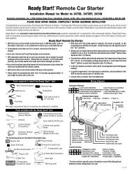
Remote Control Car Starter Installation Manual for ... - Ready Remote
Remote Control Car Starter Installation Manual for ... - Ready Remote
Remote Control Car Starter Installation Manual for ... - Ready Remote

Create successful ePaper yourself
Turn your PDF publications into a flip-book with our unique Google optimized e-Paper software.
On cars with airbags, you may notice bright yellow tubes or harnesses<br />
marked SRS (Supplemental Restraint System) underneath the steering<br />
column area. DO NOT tamper with these wires in any way, to prevent<br />
personal injury and/or damage to the air bag system.<br />
Battery gases are explosive.<br />
Do not smoke while working near the car’s battery.<br />
Note: Some installers connect a battery charger to the vehicle’s battery during<br />
installation. This is fine, but it must be removed be<strong>for</strong>e running the vehicle under<br />
remote starter control.<br />
All General Motors (GM), rear wheel drive vehicles built prior to 1995<br />
with automatic transmissions and Dodge Dakota trucks (4 cylinder<br />
engines only) with automatic transmissions built prior to 1996 have a<br />
MECHANICAL TYPE of NEUTRAL SAFETY SWITCH. See important<br />
warning on the last page of these instructions.<br />
When running the wires through the car’s firewall, be sure to protect<br />
them from sharp metal edges and from hot surfaces on and around the<br />
engine.<br />
INSTALLATION INSTRUCTIONS<br />
1. Be<strong>for</strong>e You Start<br />
Take time to read through the whole installation manual be<strong>for</strong>e beginning.<br />
Always leave a window open to avoid locking your keys in your car.<br />
IMPORTANT: After having read the entire manual, start the installation<br />
by putting the yellow WARNING STICKER in the engine compartment.<br />
Choose a surface that is clean and readily visible when the hood is open.<br />
WARNING<br />
This car is equipped with a remote control starting device.<br />
Disable be<strong>for</strong>e working on car!<br />
AVERTISSEMENT<br />
Ce véhicule est équipé d’un systéme de démarrage a distance. Mettez-le<br />
hors fonction avant d’eflectuer toute opération d’entretien ou de réparation!<br />
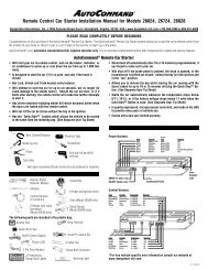
POWER & IGNITION HARNESS<br />
The remote starter module will be installed under the dash once all wiring has been<br />
completed. Do not mount the module at this time! You will need to check<br />
the red diagnostic LED light as the installation progresses. Locate (or<br />
drill) a hole in the firewall to run the PURPLE and GREEN wires of the <strong>Control</strong><br />
Harness and the PINK wire of the Power Harness into the engine compartment.<br />
The remaining short wires stay in the passenger area. Leave about a foot of the wire<br />
harness under the dash <strong>for</strong> ease of working and visual access to the diagnostic light.<br />
The <strong>Installation</strong> In<strong>for</strong>mation section of our web site www.designtech-intl.com is<br />
available 24 hours/day to provide you with free, up-to-date vehicle wiring in<strong>for</strong>mation<br />
<strong>for</strong> your particular vehicle after you log in.<br />
Note: Always connect the PINK and BLACK wires be<strong>for</strong>e connecting any of the<br />
other wires. Do not insert the fuse until step 11.<br />
2. Black Wire (16 AWG) – Ground<br />
Connect the BLACK wire to a very good, clean chassis ground in the driver’s kick<br />
panel area. Use the small ring terminal. (The thin metal bracing around or beneath<br />
the dash board is not always adequate.)<br />
3. Pink Wire (12 AWG) – Power (+12 Volts)<br />
Connect the ring terminal at the end of the short PINK wire to the +12 Volt terminal of<br />
the battery. Run the long PINK wire through the firewall of your vehicle. Join the<br />
remaining ends of the power wire together by soldering them. Tape with electrical<br />
tape to leave no exposed wires. Alternatively, you may wish to use the yellow butt<br />
connector, but we recommend soldering. Wait to insert the 30 amp green fuse into<br />
the holder until step 11. As the power is first applied to the unit the red diagnostic<br />
LED light will blink once.<br />
Note: Failure to properly install the fuse holder and 30 amp fuse to the PINK wire to<br />
the battery voids all product warranties.<br />
Ignition Key Diagram <strong>for</strong> Steps 4-7<br />
The vehicle’s wires are found coming off of the key switch.<br />
Remove the panel under the steering column to access<br />
these wires.<br />
4. Blue Wire (14 AWG) – Ignition 1<br />
Connect the BLUE wire to the ignition 1 wire of your vehicle. This wire will measure<br />
+12 Volts on the test meter in the “run” and “start” position, and is off in the “lock/<br />
off” and “accessory” positions.<br />
5. Green (14 AWG) – Ignition 2<br />
Connect the GREEN wire to the Ignition 2 wire in the vehicle. The Ignition 2 wire can<br />
function in several different ways in your vehicle. It is important to understand how it<br />
works. The Ignition 2 wire will usually measure +12 Volts in the “run” position and is<br />
off (ground) in the “lock/off” and “accessory” positions. In certain vehicles, it may<br />
also show +12 Volts in the “Start” position or Ignition 2 may turn OFF during “Crank”<br />
and turn back ON after the starter disengages. <strong>Car</strong>efully note the function of the Ignition<br />
2 wire. If the Ignition 2 turns OFF during “Crank”, set Option #4 (in section 24). If<br />
Ignition 2 stays ON during “Crank,” no options need to be changed.<br />
6. White Wire (14 AWG) – Accessory<br />
Connect the WHITE wire to the accessory wire which is +12 Volts in the “run” and<br />
“accessory” position, but off in the “start” and “off” positions. In GM vehicles, connect<br />
the white wire to the orange wire that is hot in “run” only.<br />
7. Yellow (14 AWG) – <strong>Starter</strong><br />
Connect the YELLOW wire to the starter wire. This wire will measure +12 Volts on<br />
the test meter in the “start” position only.<br />
Note: Most Nissan vehicles have two starter wires. Connect both starter wires of the<br />
vehicle to the YELLOW start wire of the remote starter.<br />
8A. Plug-In On/0ff Switch<br />
Mount the control switch so that it is easily accessible and so that<br />
the “ON” position is facing upward. Make sure there is enough clearance behind the<br />
mounted switch <strong>for</strong> the wire connections. Do not let the switch wires touch ground.<br />
Do not plug the switch into the unit until it is mounted first. Connection of this switch<br />
is mandatory. Use a 1/4" drill-bit <strong>for</strong> the mounting hole.<br />
Plug the ON/OFF control switch into the module just to the right of the power wires.<br />
Turn the switch on.<br />
8B. Plug-In LED Light<br />
Drill a 5/16" hole in to the dash or panel to mount the LED light and plug the LED<br />
light plug into the red connector. Mounting the LED light is not mandatory but the<br />
LED light is used <strong>for</strong> alarm status, troubleshooting and programming options.<br />
CONTROL HARNESS<br />
ALL WIRES ARE THE SMALLER 18 AWG SIZE<br />
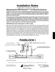
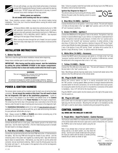
9. Purple Wire – Hood Pin Switch – <strong>Control</strong> Harness<br />
The hood pin switch MUST be installed with the remote starter. It prevents operation<br />
of the remote starter when the hood is open and is used to initialize the unit. Connect<br />
the PURPLE wire to the hood pin switch using the red<br />
connector.<br />
Note: If you already have a hood pin switch which is<br />
being used by a car alarm system, you may share the<br />
wiring – but be sure to diode isolate each wire going to<br />
the hood pin switch with the bands of diodes pointing<br />
towards the pin switch as shown at right.<br />
To Alarm<br />
To <strong>Remote</strong> <strong>Starter</strong><br />
How to share a hood pin<br />
switch with an alarm<br />
v3.1 2428<br />
2