for the proposed 800 MW Combined Cycle Power Plant ...
for the proposed 800 MW Combined Cycle Power Plant ...
for the proposed 800 MW Combined Cycle Power Plant ...

Create successful ePaper yourself
Turn your PDF publications into a flip-book with our unique Google optimized e-Paper software.
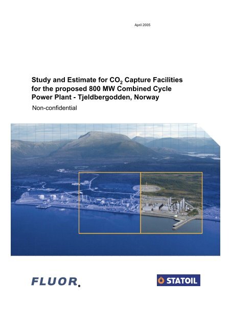
April 2005<br />
Study and Estimate <strong>for</strong> CO 2<br />
Capture Facilities<br />
<strong>for</strong> <strong>the</strong> <strong>proposed</strong> <strong>800</strong> <strong>MW</strong> <strong>Combined</strong> <strong>Cycle</strong><br />
<strong>Power</strong> <strong>Plant</strong> - Tjeldbergodden, Norway<br />
Non-confidential
CO 2 Capture Study<br />
For <strong>800</strong> <strong>MW</strong> <strong>Power</strong> <strong>Plant</strong> – Tjeldbergodden<br />
TABLE OF CONTENTS<br />
1.0 EXECUTIVE SUMMARY<br />
1.0 Executive Summary<br />
2.0 BASIS OF DESIGN<br />
2.1 <strong>Power</strong> <strong>Plant</strong><br />
2.2 CO 2 <strong>Plant</strong><br />
2.3 Process Design Basis<br />
2.4 Codes and Standards<br />
2.5 Units of Measurement<br />
2.6 Equipment Numbering<br />
2.7 <strong>Power</strong> <strong>Plant</strong> Design Assumptions<br />
3.0 PROCESS DESCRIPTION & DISCUSSIONS.<br />
3.1 CO 2 Capture<br />
3.2 Cooling Water Supplies<br />
3.3 Energy Integration<br />
3.4 Off Gas Plume Dispersion<br />
3.5 Emissions and Effluents<br />
3.6 Process Utility Interfaces<br />
3.7 <strong>Power</strong> <strong>Plant</strong> Pre-investment<br />
4.0 KEY DELIVERABLES –<br />
PFD’s, UFD’s, Mass Balances, Equipment List<br />
4.1 Block Flow Diagram<br />
4.2 PFD Economine FG Plus<br />
4.3 PFD Economine FG Plus – Compression<br />
4.4 Heat and Material Balances<br />
4.5 UFD Cooling Water<br />
4.6 Water Balance<br />
4.7 Equipment list<br />
5.0 FACILITIES LAYOUT<br />
5.1 Montage of <strong>Plant</strong><br />
5.2 3D Perspective of CO 2 <strong>Plant</strong><br />
5.3 Plot Plan CO 2 plant<br />
6.0 CAPEX ESTIMATE<br />
6.0 Total Installed Cost<br />
CB2005-0022_Final Report.Doc
CO 2 Capture Study<br />
For <strong>800</strong> <strong>MW</strong> <strong>Power</strong> <strong>Plant</strong> – Tjeldbergodden<br />
1.0 EXECUTIVE SUMMARY<br />
1.1 Introduction<br />
Statoil ASA are proposing to build an <strong>800</strong> <strong>MW</strong> combined cycle power plant as part<br />
of <strong>the</strong> overall expansion of <strong>the</strong>ir methanol plant facilities at Tjeldbergodden. The<br />
plant will comprise two gas turbines, two HRSGs and a single steam turbine. As<br />
part of <strong>the</strong> <strong>Power</strong> <strong>Plant</strong> Statoil are considering using Fluor’s Economine FG +<br />
CO 2 capture licensed technology <strong>for</strong> emission control.<br />
1.2 Executive Summary<br />
Fluor have developed and licensed a CO 2 capture technology to be used <strong>for</strong><br />
capture of acid gases in an oxidising environment where normal amines are<br />
rapidly degraded, such as are found in <strong>the</strong> exhaust gases of a combined cycle<br />
power plant.<br />
Statoil ASA engaged Fluor to undertake selective studies leading to <strong>the</strong><br />
development of a capital cost estimate <strong>for</strong> <strong>the</strong> process facilities comprising <strong>the</strong><br />
CO 2 capture plant, to be incorporated on an adjacent plot to <strong>the</strong> <strong>proposed</strong> power<br />
plant facilities at Tjeldbergodden.<br />
This report, which presents <strong>the</strong> non-confidential aspects of this study, outlines <strong>the</strong><br />
studies undertaken to define <strong>the</strong> design basis <strong>for</strong> <strong>the</strong> CO 2 <strong>Plant</strong>, establishes <strong>the</strong><br />
interface considerations, and assess <strong>the</strong> issues that may influence <strong>the</strong> design<br />
requirements of <strong>the</strong> power plant. The study draws conclusions that support <strong>the</strong><br />
completion of <strong>the</strong> capital cost estimate <strong>for</strong> this plant.<br />
In summary, <strong>the</strong> report concludes that a CO 2 capture plant can be built as an<br />
integral addition to <strong>the</strong> power plant <strong>for</strong> an indicated total installed cost of $500.MM<br />
CB2005-0022_Final Report.Doc
CO 2 Capture Study<br />
For <strong>800</strong> <strong>MW</strong> <strong>Power</strong> <strong>Plant</strong> – Tjeldbergodden<br />
2.0 BASIS OF DESIGN<br />
2.1 Introduction<br />
This section presents <strong>the</strong> general design criteria <strong>for</strong> <strong>the</strong> CO 2 Capture Study at<br />
Tjeldbergodden, Base Scope – <strong>800</strong> <strong>MW</strong> <strong>Power</strong> <strong>Plant</strong>.<br />
Statoil is planning to install a combined cycle (CC) power plant based on 2<br />
commercially available gas turbines (GT) in <strong>the</strong> 250 -300 <strong>MW</strong> class with dedicated<br />
waste heat boilers and one common steam turbine whose nominal power output<br />
would be <strong>800</strong> <strong>MW</strong>. The flue gas quantity and quality from <strong>the</strong> two GTs was<br />
estimated by Fluor using standard software.<br />
Statoil is assessing <strong>the</strong> feasibility of capturing carbon dioxide from <strong>the</strong>se two new<br />
plants <strong>for</strong> Enhanced Oil Recovery (EOR) using Fluor’s proprietary Econamine FG<br />
Plus SM (EFG+) technology. The carbon dioxide recovery is set at 85% resulting in<br />
an EFG+ plant with a 6,170 Te/day (100% CO 2 ) capacity.<br />
2.2 Site Data<br />
• The EFG+ plant is located at Statoil’s existing complex in Tjeldbergodden,<br />
Norway.<br />
2.3 Process Design Basis<br />
Design Philosophy<br />
The EFG+ plant consists of three absorption trains and one common stripper<br />
train. Three was chosen <strong>for</strong> <strong>the</strong> number of absorption trains based on <strong>the</strong><br />
maximum allowable diameter of 15 meters <strong>for</strong> each absorber column.<br />
<strong>Plant</strong> Life<br />
The plant is designed <strong>for</strong> an operating life of no less than thirty (30) years.<br />
On-Stream Factor<br />
All systems are designed to achieve a minimum on-stream availability of 330 days<br />
per year.<br />
CB2005-0022_Final Report.Doc
CO 2 Capture Study<br />
For <strong>800</strong> <strong>MW</strong> <strong>Power</strong> <strong>Plant</strong> – Tjeldbergodden<br />
Feedstock Properties<br />
The properties of <strong>the</strong> flue gas from <strong>the</strong> gas turbines were estimated by Fluor using<br />
<strong>the</strong> GTPRO program and are provided in Table 2-1.<br />
Table 2-1 – EFG+ <strong>Plant</strong> Feedstock Properties<br />
Description<br />
Flue Gas<br />
Temperature, °C 80<br />
Pressure, kg/cm 2 (g) 0<br />
Flow, kg/s 1384.8<br />
Composition (vol%)<br />
Nitrogen 74.65<br />
Oxygen 12.70<br />
Carbon Dioxide 3.91<br />
Water 7.84<br />
Argon 0.90<br />
SO 2<br />
0 ppm<br />
NO<br />
22 ppm<br />
NO 2 Component of NOx<br />
3 ppm<br />
NOx Total<br />
25 ppm<br />
Product Specification<br />
The specification of <strong>the</strong> carbon dioxide product is shown in Table 2-2.<br />
Table 2-2 – Product Specification at Battery<br />
Limits<br />
Water<br />
Description<br />
Specification<br />
50 ppmw (max)<br />
Pressure, kg/cm 2 (g) 102<br />
CB2005-0022_Final Report.Doc
CO 2 Capture Study<br />
For <strong>800</strong> <strong>MW</strong> <strong>Power</strong> <strong>Plant</strong> – Tjeldbergodden<br />
Utilities<br />
The conditions <strong>for</strong> <strong>the</strong> utilities are shown in Table 2-3.<br />
Table 2-3 – Utilities<br />
Temperature<br />
°C<br />
Pressure,<br />
kg/cm 2 (g)<br />
Low Pressure Steam 148 3.5<br />
Medium Pressure Steam 160 5.4<br />
Make-up Water 40 6.5-7.0<br />
Sea Water Cooling Water Supply 18 4.5<br />
O<strong>the</strong>r required utilities are:<br />
• Service water<br />
• Steam condensate return<br />
• <strong>Plant</strong> and instrument air<br />
• Nitrogen <strong>for</strong> blanketing<br />
2.4 Codes and Standards<br />
Return<br />
28 (max)<br />
Fluor standards are used <strong>for</strong> <strong>the</strong> equipment codes and standards (e.g. ASME,<br />
API, TEMA, ANSI).<br />
2.5 Units of Measurement<br />
All units of measurement are in <strong>the</strong> metric system and are shown in Table 5-1.<br />
Table 5-1<br />
Units of Measurement<br />
Temperature °C<br />
Pressure (gauge)<br />
(absolute)<br />
kg/cm 2 (g)<br />
kg/cm 2 (a)<br />
Vacuum<br />
mm H 2 O<br />
Liquid flow<br />
m 3 /hr, kg/hr<br />
Steam flow<br />
kg/hr<br />
Gas flow<br />
Nm 3 /hr<br />
(at 0°C & 760 mmHg)<br />
Heat flow<br />
kcal, Gcal<br />
<strong>Power</strong><br />
kW<br />
Viscosity<br />
cP<br />
Dimensions<br />
m, mm<br />
CB2005-0022_Final Report.Doc
CO 2 Capture Study<br />
For <strong>800</strong> <strong>MW</strong> <strong>Power</strong> <strong>Plant</strong> – Tjeldbergodden<br />
2.6 Equipment Numbering<br />
Every piece of equipment is identified with an identification letter symbol indicating<br />
<strong>the</strong> equipment type and a three-digit item number with <strong>the</strong> notation A/B in <strong>the</strong><br />
presence of a spare. The following table shows <strong>the</strong> different identification letter<br />
symbols.<br />
Equipment Identification<br />
Letter Symbol<br />
BL<br />
C<br />
E<br />
F<br />
K<br />
P<br />
PK<br />
SU<br />
T<br />
V<br />
Equipment / Instrument<br />
Blowers<br />
Columns/Towers<br />
Heat Exchangers and Coolers<br />
Filters<br />
Compressors<br />
Pumps<br />
Vendor Packages<br />
Sumps<br />
Tanks<br />
Vessels<br />
An example of equipment numbering is BL-100 <strong>for</strong> <strong>the</strong> Blower.<br />
2.7 <strong>Power</strong> plant design assumptions.<br />
GT Master Simulations. ( For Simulation Reports See Section 4.8)<br />
The exhaust gas composition was obtained from <strong>the</strong> GT-Pro simulation. As an<br />
input, <strong>the</strong> following gas composition which had been provided by Statoil was<br />
applied under <strong>the</strong> title Statoil Gas.<br />
Component<br />
Percentage by<br />
volume<br />
Nitrogen 0.39<br />
Carbon Dioxide 2.03<br />
Methane 86.65<br />
Ethane 6.52<br />
Propane 2.29<br />
Butane 1.27<br />
Pentane 0.46<br />
Hexane 0.39<br />
TOTAL 100.00<br />
From this analysis GT-Pro calculated <strong>the</strong> Lower Calorific Value at 25°C as 46662<br />
kJ/kg, and a molecular weight of 19.28. The calorific value was applied to give<br />
<strong>the</strong> correct combustion conditions in <strong>the</strong> gas turbine which results in <strong>the</strong> fuel flow<br />
rate and hence <strong>the</strong> exhaust gas composition was derived.<br />
CB2005-0022_Final Report.Doc
3.0 PROCESS DESCRIPTION & DISCUSSIONS.<br />
CO 2 Capture Study<br />
For <strong>800</strong> <strong>MW</strong> <strong>Power</strong> <strong>Plant</strong> – Tjeldbergodden<br />
This section provides <strong>the</strong> process basis <strong>for</strong> <strong>the</strong> CO 2 capture facilities and<br />
discusses under separate headings <strong>the</strong> various <strong>Power</strong> plant interface<br />
considerations and design basis assumptions used to establish <strong>the</strong> CO 2 plant<br />
base case design.<br />
3.1 CO 2 Capture – Process Description<br />
The following is a process description <strong>for</strong> <strong>the</strong> <strong>proposed</strong> Econamine FG Plus SM<br />
(EFG+) plant that will be located at Statoil’s site in Tjeldbergodden, Norway.<br />
The plant is designed <strong>for</strong> a carbon dioxide production capacity of 6,170 Te/d. The<br />
product carbon dioxide is compressed and sent to <strong>the</strong> battery limits of <strong>the</strong> plant <strong>for</strong><br />
Enhanced Oil Recovery (EOR).<br />
The non-confidential process configuration <strong>for</strong> <strong>the</strong> EFG+ plant and carbon dioxide<br />
compression is shown in Process Flow Diagrams PFD-001 and PFD-002.<br />
The EFG+ plant battery limit <strong>for</strong> <strong>the</strong> flue gas feed is at <strong>the</strong> stacks of <strong>the</strong> Heat<br />
Recovery Steam Generators (HRSG). All of <strong>the</strong> flue gas from <strong>the</strong> two HRSGs is<br />
diverted from <strong>the</strong> stacks and is routed to <strong>the</strong> EFG+ plant thus resulting in a zero<br />
flow of gas through <strong>the</strong> stacks to <strong>the</strong> atmosphere.<br />
The tie-in points are at <strong>the</strong> two stacks where <strong>the</strong> flue gas is routed to a common<br />
header. The flue gas is <strong>the</strong>n divided equally and routed through three ducts to <strong>the</strong><br />
EFG+ plants in parallel. The following is a description of Train A <strong>for</strong> absorption,<br />
which is identical to Trains B and C. The stripper and CO 2 compression is one<br />
train common to <strong>the</strong> three absorption trains.<br />
The flue gas, at 80°C, enters <strong>the</strong> Direct Contact Cooler (DCC) (C-100) where <strong>the</strong><br />
gas is cooled to 30°C by a circulating water stream and any particulates present in<br />
<strong>the</strong> flue gas are removed by scrubbing. The flue gas and <strong>the</strong> circulating water are<br />
contacted over packing. By lowering <strong>the</strong> gas temperature, much of <strong>the</strong> water<br />
vapor contained in <strong>the</strong> flue gas is condensed and separated from <strong>the</strong> feed gas<br />
be<strong>for</strong>e entering <strong>the</strong> Absorber (C-101).<br />
The circulating water enters <strong>the</strong> DCC at 25°C and is heated to 42°C by <strong>the</strong> cooling<br />
and condensing of water vapor in <strong>the</strong> flue gas. The circulating water from <strong>the</strong><br />
DCC is routed through <strong>the</strong> DCC Water Cooler (E-100) by <strong>the</strong> DCC Circulating<br />
Water Pump (P-100A/B) and returned to <strong>the</strong> DCC. Cooling water at 18°C is used<br />
to cool <strong>the</strong> circulating water to 25°C. All cooling water used in <strong>the</strong> EFG+ plant is<br />
sea water from <strong>the</strong> cooling system in <strong>the</strong> power plant.<br />
A slip stream is diverted from <strong>the</strong> circulating water upstream of <strong>the</strong> pump and<br />
routed by <strong>the</strong> DCC Filter Pump (P-101A/B) through <strong>the</strong> DCC Circulating Water<br />
Filter (F-100) to continuously remove particulate matter. A portion of <strong>the</strong> filtered<br />
water is returned to <strong>the</strong> liquid surge volume in <strong>the</strong> bottom of <strong>the</strong> DCC. Excess<br />
water, produced in <strong>the</strong> DCC from <strong>the</strong> condensing of water vapor in <strong>the</strong> flue gas, is<br />
routed to <strong>the</strong> battery limits after filtration. The flow rate of this excess water is<br />
controlled by a flow controller with a reset by a level controller in <strong>the</strong> DCC.<br />
The cooled, overhead gas from <strong>the</strong> DCC is routed to Blower (BL-100) to<br />
overcome <strong>the</strong> pressure drop in <strong>the</strong> system. The flow rate of <strong>the</strong> feed gas to <strong>the</strong><br />
Blower is maintained by controlling <strong>the</strong> inlet guide vanes of <strong>the</strong> blower.<br />
CB2005-0022_Final Report.Doc
CO 2 Capture Study<br />
For <strong>800</strong> <strong>MW</strong> <strong>Power</strong> <strong>Plant</strong> – Tjeldbergodden<br />
The treated flue gas is routed to <strong>the</strong> Absorber (C-101). The gas flows upwards<br />
counter current to <strong>the</strong> circulating MEA solvent. The MEA solvent reacts chemically<br />
with carbon dioxide, absorbing 80-90% of <strong>the</strong> carbon dioxide in <strong>the</strong> incoming flue<br />
gas. Residue gas, mainly nitrogen and oxygen , is vented after <strong>the</strong> wash section<br />
through <strong>the</strong> top of <strong>the</strong> absorber.<br />
The rich MEA solvent from all three trains is pumped from <strong>the</strong> bottom of <strong>the</strong><br />
Absorber to <strong>the</strong> top of <strong>the</strong> Stripper (C-102) by <strong>the</strong> Rich Solvent Pump (P-103A/B).<br />
It is preheated in Solvent Cross Exchanger (E-103A-L) be<strong>for</strong>e entering <strong>the</strong> top of<br />
<strong>the</strong> stripping tower. In <strong>the</strong> Stripper, <strong>the</strong> rich MEA solvent is fur<strong>the</strong>r heated in <strong>the</strong><br />
Reboiler (E-104A/B/C/D) by means of low pressure steam, releasing <strong>the</strong> carbon<br />
dioxide.<br />
From <strong>the</strong> reboiler, <strong>the</strong> lean MEA solvent is pumped by <strong>the</strong> Lean Solvent Pump (P-<br />
104A/B/C), cooled against rich solvent in <strong>the</strong> Solvent Cross Exchanger (E-103A-L)<br />
and fur<strong>the</strong>r cooled in <strong>the</strong> Lean Solvent Cooler (E-106A/B/C). A part of <strong>the</strong> lean<br />
MEA solvent is routed through <strong>the</strong> Lean Solvent Filter (F-102) in order to remove<br />
solution contaminants. The filtered solvent returns to <strong>the</strong> main lean solvent line.<br />
The combined solvent is <strong>the</strong>n divided equally and routed to <strong>the</strong> three absorption<br />
trains.<br />
Water in <strong>the</strong> overhead gas from <strong>the</strong> Stripper is condensed in Condenser (E-<br />
105A/B) and separated from <strong>the</strong> carbon dioxide product in <strong>the</strong> Overhead<br />
Accumulator (V-100). A portion of <strong>the</strong> condensed water is returned to <strong>the</strong> Stripper<br />
with <strong>the</strong> balance being equally distributed to each of <strong>the</strong> Absorbers. The carbon<br />
dioxide product is <strong>the</strong>n sent to <strong>the</strong> battery limit.<br />
To maintain <strong>the</strong> highest possible absorption capacity of <strong>the</strong> MEA solvent,<br />
contaminants, such as heat stable salts, are removed in <strong>the</strong> Reclaimer (E-107).<br />
The Reclaimer is operated as a semi-batch process. Heat stable salts are<br />
removed using a <strong>the</strong>rmal process utilizing both LP and MP steam.<br />
The carbon dioxide product from <strong>the</strong> Overhead Accumulator is compressed in <strong>the</strong><br />
Product CO 2 Compressor (K-100) to <strong>the</strong> required 103 kg/cm 2 (a) pressure. The<br />
compressor consists of five stages with intercooling provided. Each stage of<br />
compression is followed by an air cooler (E-108, 110, 112 and 114) and trim<br />
coolers (E-109, 111, 113 and 115) where <strong>the</strong> carbon dioxide product is cooled to<br />
25°C against cooling water. After each stage of cooling, <strong>the</strong> carbon dioxide is<br />
routed to knock-out drums (V-103, 104, 105 and 106) to remove condensate. At<br />
an interstage pressure of 39.5 kg/cm 2 (a), <strong>the</strong> compressed carbon dioxide is sent<br />
to a Dehydration Package (ME-100), which reduces <strong>the</strong> moisture level down to<br />
less than 50 ppm (weight basis).<br />
3.2 Cooling Water Supplies<br />
To achieve a temperature rise of 10°C, <strong>the</strong> basic power plant requires a cooling<br />
water flow of 41500 tons per hour. After <strong>the</strong> carbon capture plant is added <strong>the</strong><br />
steam flow to <strong>the</strong> power plant condenser is greatly diminished however <strong>the</strong> flow<br />
through <strong>the</strong> condenser is unchanged so that <strong>the</strong> temperature rise now becomes<br />
5.28°C.<br />
The Carbon Dioxide capture plant has been specified to use outlet sea water from<br />
<strong>the</strong> power plant condenser as it does not have to reach such a low temperature to<br />
CB2005-0022_Final Report.Doc
CO 2 Capture Study<br />
For <strong>800</strong> <strong>MW</strong> <strong>Power</strong> <strong>Plant</strong> – Tjeldbergodden<br />
provide <strong>the</strong>rmal efficiency in <strong>the</strong> power cycle. Its consumption was based on a<br />
temperature rise of 10°C, which required a flow rate of 36750 tons per hour.<br />
It is <strong>proposed</strong> to install a booster pump to serve <strong>the</strong> carbon dioxide capture plant,<br />
which takes suction from <strong>the</strong> return sea water connection on <strong>the</strong> power plant<br />
condenser. It will boost <strong>the</strong> pressure so that <strong>the</strong>re is sufficient flow through <strong>the</strong><br />
carbon dioxide capture plant coolers and fill <strong>the</strong> system to its highest elevation,<br />
which is 6 meters above grade <strong>for</strong> <strong>the</strong> highest condenser.<br />
If <strong>the</strong>re is a weir box to control <strong>the</strong> pressure at <strong>the</strong> outlet of <strong>the</strong> power plant<br />
condenser, <strong>the</strong> suction to <strong>the</strong> booster pump and discharge from <strong>the</strong> carbon<br />
capture plant cooling system, may be made at this weir box without any<br />
connections to existing piping being required<br />
After passing through <strong>the</strong> heat exchangers <strong>the</strong> sea water is collected in <strong>the</strong> return<br />
main and is discharged to <strong>the</strong> outfall pit in <strong>the</strong> power plant. This prevents outlet<br />
sea water returning to <strong>the</strong> booster pump inlet.<br />
The system is depicted on <strong>the</strong> Cooling Water utility flow diagram, and <strong>the</strong> method<br />
of connection using <strong>the</strong> weir box in <strong>the</strong> outfall from <strong>the</strong> main power plant<br />
condenser is shown in <strong>the</strong> figure below<br />
Given a total flow of 41500 tons per hour <strong>the</strong> overall temperature rise is expected<br />
to be just above 14°C.<br />
To arrive at a specification <strong>for</strong> <strong>the</strong> booster pump an allowance of 0.7 Bar <strong>for</strong> <strong>the</strong><br />
pipework in addition to <strong>the</strong> 0.7 bar <strong>for</strong> <strong>the</strong> heat exchangers and 0.6 bar <strong>for</strong> <strong>the</strong><br />
control valves has been made. The static head difference between <strong>the</strong> level in<br />
<strong>the</strong> main weir box and <strong>the</strong> elevated weir box (see figure below) has been taken as<br />
7 metres. This give a total discharge pressure of 2.7 bar and <strong>for</strong> a flow of<br />
40000m3/h a hydraulic power of 3000kW is calculated. These are default values<br />
pending a full layout study and <strong>the</strong> investigation of operating some condensers<br />
under vacuum on <strong>the</strong> cooling water side. It is recognized <strong>the</strong>re<strong>for</strong>e that power<br />
consumptions could be optimized during plant design.<br />
CB2005-0022_Final Report.Doc
C.W. Users at Carbon Capture <strong>Plant</strong><br />
Elevated Weir Box <strong>for</strong><br />
Carbon Capture <strong>Plant</strong><br />
Return from<br />
Main<br />
Condenser<br />
Booster Pump<br />
Outfall Weir Box<br />
Outfall to Sea<br />
Flow Schematic showing Cooling Water Supply and Return connected at Outfall Weir Box
CO 2 Capture Study<br />
For <strong>800</strong> <strong>MW</strong> <strong>Power</strong> <strong>Plant</strong> – Tjeldbergodden<br />
3.3 Energy Integration<br />
In a conventional <strong>Combined</strong> <strong>Cycle</strong> Gas Turbine power plant <strong>the</strong> steam circuit<br />
is arranged to follow <strong>the</strong> decay in temperature of <strong>the</strong> exhaust gas as heat is<br />
abstracted to give <strong>the</strong> most efficient <strong>the</strong>rmal cycle as shown below:<br />
HP Steam<br />
Source<br />
Reheat<br />
Coils<br />
IP Steam<br />
Source<br />
LP Steam<br />
Source<br />
Condenser<br />
Conventional Steam Circuit <strong>for</strong> CCGT <strong>Power</strong> <strong>Plant</strong><br />
Where a plant is to be fitted with Carbon Dioxide capture, a considerable<br />
amount of heat is required <strong>for</strong> <strong>the</strong> regeneration of <strong>the</strong> scrubbing liquor. We<br />
have <strong>for</strong>mulated a number of rules, which will give <strong>the</strong> best <strong>the</strong>rmal efficiency<br />
of <strong>the</strong> total unit and are:<br />
1. Add “source heat at as high a temperature as possible so as to achieve<br />
<strong>the</strong> highest possible Carnot efficiency (set by source and sink<br />
temperatures). Add this heat to <strong>the</strong> highest efficiency combustion system<br />
and do nt add auxiliary low efficiency combustion devices.<br />
2. Reject heat to <strong>the</strong> “sink” at as low a temperature as possible<br />
3. Extract as much work from <strong>the</strong> working fluids in <strong>the</strong> expansion turbines of<br />
<strong>the</strong> power train and only extract LP steam <strong>for</strong> amine reboilers at <strong>the</strong><br />
lowest possible pressure and temperature.<br />
4. Reject as little heat as possible to <strong>the</strong> “sink” and utilise as much waste<br />
heat as possible without violating any pinch rules<br />
5. Use <strong>the</strong> lowest possible energy in <strong>the</strong> amine stripper. This requires <strong>the</strong><br />
use of <strong>the</strong> best solvents plus intensive integration within <strong>the</strong> amine<br />
capture plant.<br />
In designing a plant where <strong>the</strong> CO 2 capture plant is commissioned with <strong>the</strong><br />
power plant, <strong>the</strong> steam turbine is sized so that it is working under optimum<br />
conditions when steam is being extracted <strong>for</strong> <strong>the</strong> CO 2 capture plant.<br />
If <strong>the</strong> CO 2 capture plant is to be commissioned some time after <strong>the</strong> power<br />
plant, <strong>the</strong>n one can ei<strong>the</strong>r:<br />
CB2005-0022_Final Report.Doc
CO 2 Capture Study<br />
For <strong>800</strong> <strong>MW</strong> <strong>Power</strong> <strong>Plant</strong> – Tjeldbergodden<br />
1. The alternative of using an auxiliary boiler to provide <strong>the</strong> steam <strong>for</strong> <strong>the</strong><br />
CO2 capture plant has been demonstrated to be of lesser <strong>the</strong>rmal<br />
efficiency<br />
If <strong>the</strong> rules of integration are to be followed <strong>the</strong>n <strong>the</strong> alternatives are:<br />
2. Install <strong>the</strong> optimum steam turbine <strong>for</strong> <strong>the</strong> capture case and accept <strong>the</strong><br />
inefficiency resulting while <strong>the</strong> capture plant is not present.<br />
3. Install <strong>the</strong> optimum steam turbine <strong>for</strong> <strong>the</strong> capture case and add a small<br />
steam turbine to accept <strong>the</strong> steam which will be used by <strong>the</strong> capture plant<br />
when it is eventually commissioned<br />
4. Install <strong>the</strong> optimum steam turbine <strong>for</strong> <strong>the</strong> non-capture case and accept <strong>the</strong><br />
inefficiency resulting after <strong>the</strong> capture plant is commissioned and <strong>the</strong><br />
plant will be configured as shown below<br />
HP Steam<br />
Source<br />
Reheat<br />
Coils<br />
IP Steam<br />
Source<br />
LP Steam<br />
Source<br />
Condenser<br />
Steam to CO 2<br />
capture plant<br />
Steam Circuit <strong>for</strong> CCGT <strong>Power</strong> <strong>Plant</strong> with steam extraction <strong>for</strong> CO 2<br />
capture plant<br />
GT-Master versions of <strong>the</strong> abated and non-abated cases were made and<br />
used to demonstrate each case in <strong>the</strong> off design <strong>for</strong>m. The net <strong>the</strong>rmal<br />
efficiencies obtained are:<br />
With Extract Without Extract<br />
Small LP Turbine (Abated case) 51.71% 55.31%<br />
Large LP Turbine (Non-abated case) 51.50% 56.63%<br />
In reality <strong>the</strong>se results show so little difference between ei<strong>the</strong>r configuration of<br />
turbine that <strong>the</strong>re is no point in considering <strong>the</strong> addition of a small temporary<br />
turbine (alternative 3 above). Alternative 4 will give a marginally greater<br />
output until <strong>the</strong> Carbon dioxide capture plant is commissioned but <strong>the</strong> capital<br />
cost of <strong>the</strong> turbine is likely to be higher. It is suggested that options 2 & 4<br />
should be developed during detailed design with a turbine supplier when <strong>the</strong><br />
costs can be developed in greater detail and when <strong>the</strong> minor per<strong>for</strong>mance<br />
differences can be quantified with assurance.<br />
CB2005-0022_Final Report.Doc
CO 2 Capture Study<br />
For <strong>800</strong> <strong>MW</strong> <strong>Power</strong> <strong>Plant</strong> – Tjeldbergodden<br />
3.4 Off Gas Plume Dispersion<br />
Stack Gas from Absorber Towers<br />
The stack gas has been passed through <strong>the</strong> absorber towers, <strong>the</strong>re<strong>for</strong>e it will<br />
have been saturated with water as well as having had <strong>the</strong> majority of its acidic<br />
components removed.<br />
These acidic components include oxides of nitrogen as well as carbon<br />
dioxide. Thus <strong>the</strong> final effluent gas will be air from which a portion of <strong>the</strong><br />
oxygen has been removed and which is saturated with water vapour at 37°C.<br />
The gas is not hazardous to life, however upon contact with cooler air, a<br />
visible plume of water vapour will <strong>for</strong>m. Under freezing conditions this could<br />
<strong>for</strong>m ice on exposed cold surfaces.<br />
The need <strong>for</strong> plume dispersal by heating or dilution with ambient air, will<br />
depend on <strong>the</strong> location of <strong>the</strong> plume in relation to access roads and work<br />
areas, where it could reduce visibility; and structures, where icing could lead<br />
to overloading of such structures. It is recommended that this be studied in a<br />
later phase.<br />
3.5 Emissions and Effluents Introduction<br />
The Econamine FG Plus SM (EFG+) process produces three main<br />
emissions/effluents:<br />
• Absorber Stack Emissions: MEA and Ammonia<br />
• Reclaimer Waste<br />
• DCC Excess Water containing dissolved carbon dioxide<br />
3.5.1 Absorber Stack Emissions<br />
The expected concentrations of MEA and ammonia in <strong>the</strong> absorber stack gas<br />
are as follows.<br />
Expected Emissions<br />
Expected<br />
Emissions<br />
MEA<br />
Ammonia<br />
ppmv 0.2 23<br />
3.5.2 Reclaimer Waste<br />
Heat stable salts (HSS) are <strong>for</strong>med in <strong>the</strong> EFG+ process due to acid-base<br />
reaction between MEA and different acid products present in <strong>the</strong> flue gas or in<br />
<strong>the</strong> solution, including:<br />
• SO 2 and SO 3 in <strong>the</strong> flue gas<br />
• The NO 2 portion of NO x in <strong>the</strong> flue gas<br />
• Small quantities of acids generated by oxidation MEA<br />
CB2005-0022_Final Report.Doc
CO 2 Capture Study<br />
For <strong>800</strong> <strong>MW</strong> <strong>Power</strong> <strong>Plant</strong> – Tjeldbergodden<br />
HSS are removed from <strong>the</strong> system using <strong>the</strong>rmal reclaiming. The expected<br />
amount of reclaimer waste and a typical waste composition as follows.<br />
Table 2<br />
Reclaimer Waste<br />
Expected Amount Tonnes/yr 2,300<br />
Composition<br />
MEA %wt 15<br />
Water %wt 7<br />
MEA Degradation Products %wt 75<br />
Inorganic Residue %wt 3<br />
3.5.3 DCC Excess Water<br />
The hot flue gas from <strong>the</strong> Heat Recovery Steam Generators must first be<br />
cooled to <strong>the</strong> operating conditions of <strong>the</strong> EFG+ plant to minimize amine<br />
degradation. The gas is cooled in <strong>the</strong> Direct Contact Cooler (DCC) by a<br />
circulating water stream. By lowering <strong>the</strong> gas temperature, much of <strong>the</strong> water<br />
vapor contained in <strong>the</strong> flue gas is condensed and separated from <strong>the</strong> feed<br />
upstream of <strong>the</strong> absorber. The condensed water from <strong>the</strong> flue gas is taken<br />
out of <strong>the</strong> DCC with <strong>the</strong> hot circulating water. A slip stream of excess water is<br />
taken from <strong>the</strong> circulating water stream to maintain <strong>the</strong> water balance around<br />
<strong>the</strong> DCC. This DCC excess water contains some dissolved carbon dioxide<br />
and is combined with <strong>the</strong> cooling water return. The expected amount of DCC<br />
excess water is shown in table 3.<br />
Table 3<br />
DCC Excess Water<br />
Expected Amount m 3 /hr 116.4<br />
pH pH 5.0 – 5.5<br />
It is <strong>proposed</strong> that this water be used as demineralized plant make-up after<br />
degassing <strong>the</strong> carbon dioxide.<br />
3.6 Process Utility Interfaces<br />
The following table provides a listing of <strong>Power</strong> plant utility interfaces with<br />
relevant stream in<strong>for</strong>mation.<br />
ECONAMINE FG PLUS SM INTERFACE TABLE<br />
Commodity Unit In/Out Flow Temp.<br />
(°C)<br />
Pressure<br />
BAR(G)<br />
PROCESS<br />
Flue Gas<br />
Vent Gas<br />
CO 2 Product<br />
DCC Excess<br />
Water<br />
1000 m 3 /hr<br />
(actual)<br />
1000 m 3 /hr<br />
(actual)<br />
m 3 /hr<br />
(actual)<br />
Te/hr<br />
In 5,090 80 0.0<br />
Out 4,231 37 0.0<br />
Out 90,361 25 0.6<br />
Out 115.5 42 2.5<br />
UTILITIES<br />
Demin Water Te/hr In 55.2 40 7.0<br />
CB2005-0022_Final Report.Doc
CO 2 Capture Study<br />
For <strong>800</strong> <strong>MW</strong> <strong>Power</strong> <strong>Plant</strong> – Tjeldbergodden<br />
Seawater<br />
Coolant Te/hr In 36,750 18<br />
2.7 @ Booster<br />
Pump Discharge<br />
Seawater<br />
Coolant<br />
Te/hr Out 36,750 28<br />
Low Pressure<br />
Steam Te/hr In 424.4 148 3.5<br />
Medium<br />
Pressure Steam<br />
Condensate<br />
Nitrogen<br />
Instrument Air<br />
CB2005-0022_Final Report.Doc<br />
ATM @ 7m<br />
elevation<br />
Te/hr In 24.1 (Note 1) 161 5.4<br />
Te/hr Out 424.4 147 7.2<br />
Nm 3 /hr In 4,839 30 7.0<br />
Nm 3 /hr In 122 30 7.0<br />
Notes:<br />
1) Medium Pressure Steam is required intermittently towards <strong>the</strong> end of <strong>the</strong> reclaiming cycle<br />
(8-12 hours per month).<br />
2) Pressure drop across water cooled exchangers = 0.7 BAR. Add additional 0.6 BAR <strong>for</strong><br />
variable loss. Pressure loss in inlet lines allowance = 0.7 BAR. Elevation of outlet weir<br />
box taken as 7 meters.<br />
3.7 <strong>Power</strong> <strong>Plant</strong> Pre-investment<br />
It is anticipated that limited pre investment would be required in <strong>the</strong> <strong>Power</strong><br />
plant to accommodate <strong>the</strong> carbon capture plant. Main pre investment would<br />
be in <strong>the</strong> specification of <strong>the</strong> HRSG and <strong>the</strong> steam turbine where a change to<br />
<strong>the</strong> specification of <strong>the</strong> equipment is best accommodated prior to purchase.<br />
Recommended changes to <strong>the</strong> specification are as follows.<br />
Qualifications to HRSG Specification to facilitate addition of Carbon Capture<br />
`<strong>Plant</strong><br />
1. Steam Extracted <strong>for</strong>m <strong>the</strong> crossover <strong>for</strong>m <strong>the</strong> IP to LP sections of <strong>the</strong><br />
turbine should be arranged to be at 4.6 Bar (a) at <strong>the</strong> turbine, so as to suit<br />
<strong>the</strong> temperature requirement of <strong>the</strong> carbon capture plant.<br />
2. Low pressure steam supply to <strong>the</strong> Carbon Capture <strong>Plant</strong> is to be supplied<br />
from <strong>the</strong> boiler drum plus extraction <strong>for</strong> <strong>the</strong> IP/LP crossover of <strong>the</strong> steam<br />
turbine. It will be desuperheated to near saturation conditions using an<br />
enthalpy controlled desuperheater. (See attached sketch at <strong>the</strong> end of this<br />
section.)<br />
3. No provision <strong>for</strong> a LP superheater is needed<br />
4. Preferred configuration of <strong>the</strong> HRSG is horizontal to enable <strong>the</strong> ductwork<br />
to <strong>the</strong> Carbon Capture plant to be arranged <strong>for</strong> minimum pressure loss<br />
5. Space provision should be made so that <strong>the</strong> structure of <strong>the</strong> HRSG can<br />
have a diverter damper installed at a later date, which will divert flue gas<br />
from <strong>the</strong> stack to <strong>the</strong> future Carbon Capture <strong>Plant</strong><br />
Qualifications to Steam Turbine Specification to facilitate addition of Carbon<br />
Capture <strong>Plant</strong><br />
1. Pressure at <strong>the</strong> IP/LP crossover to be 4.6 bar(a)<br />
2. The turbine is to be constructed to enable <strong>the</strong> later addition of controlled<br />
steam extraction from <strong>the</strong> IP/LP crossover.<br />
3. The actual LP steam pressure supplied should be controlled at <strong>the</strong> turbine<br />
to meet <strong>the</strong> load on <strong>the</strong> carbon capture plant
CO 2 Capture Study<br />
For <strong>800</strong> <strong>MW</strong> <strong>Power</strong> <strong>Plant</strong> – Tjeldbergodden<br />
Sea Water Off Take.<br />
Sea water <strong>for</strong> cooling of <strong>the</strong> carbon capture plant is taken from <strong>the</strong> main<br />
<strong>Power</strong> plant cooling water supply. It is <strong>the</strong>re<strong>for</strong>e recommended that <strong>the</strong> Wier<br />
Box associated with <strong>the</strong> SW return from <strong>the</strong> main condenser is sized sufficient<br />
to accommodate <strong>the</strong> suction and discharge piping to and from <strong>the</strong> carbon<br />
capture plant.<br />
As shown in <strong>the</strong> attached accompanying diagram.<br />
CB2005-0022_Final Report.Doc
CO 2 Capture Study<br />
For <strong>800</strong> <strong>MW</strong> <strong>Power</strong> <strong>Plant</strong> – Tjeldbergodden<br />
FW<br />
13.14p<br />
26T<br />
109.8h<br />
785.3M<br />
5.274p<br />
26T<br />
109.8h<br />
785.3M<br />
LPE<br />
103560 Q<br />
5.12p<br />
139T<br />
584.5h<br />
785.3M<br />
LPB<br />
65766 Q<br />
5.12p<br />
153T<br />
2748.6h<br />
90.23M<br />
ST extraction<br />
5.12p<br />
304T<br />
3073h<br />
289.2M<br />
695.1 M<br />
HP/IP<br />
5.12 p<br />
153 T<br />
2748.6 h<br />
90.23 M<br />
4.592p<br />
149T<br />
2739.3h<br />
424.4M<br />
45 M<br />
CB2005-0022_Final Report.Doc
4.0 KEY DELIVERABLES –<br />
PFD’S, UFD’S, Mass Balances, Equipment List<br />
CO 2 Capture Study<br />
For <strong>800</strong> <strong>MW</strong> <strong>Power</strong> <strong>Plant</strong> – Tjeldbergodden<br />
4.1 Block Flow Diagram<br />
CB2005-0022_Final Report.Doc
Battery Limits<br />
Flue Gas to<br />
Atmosphere<br />
Gas<br />
Turbine 1<br />
HRSG<br />
1<br />
Stack<br />
Gas<br />
NNF<br />
Excess<br />
Water<br />
DCC<br />
Train A<br />
Cooling<br />
Water<br />
Return<br />
Blower<br />
Train A<br />
Cooling<br />
Water<br />
Supply<br />
Absorber<br />
Train A<br />
Flue Gas to<br />
Atmosphere<br />
Steam<br />
Reclaimer<br />
Condensate<br />
Dehydration<br />
Package<br />
CO 2<br />
Compressor<br />
Carbon Dioxide<br />
Product<br />
6,170 MTPD<br />
Gas<br />
Turbine 2<br />
HRSG<br />
2<br />
Stack<br />
Gas<br />
NNF<br />
Excess<br />
Water<br />
DCC<br />
Train B<br />
Cooling<br />
Water<br />
Return<br />
Cooling<br />
Water<br />
Supply<br />
Blower<br />
Train B<br />
Absorber<br />
Train B<br />
Flue Gas to<br />
Atmosphere<br />
Steam<br />
Stripper<br />
Reboiler<br />
Condensate<br />
Cooling<br />
Water<br />
Return<br />
Cooling<br />
Water<br />
Supply<br />
DCC<br />
Train C<br />
Blower<br />
Train C<br />
Absorber<br />
Train C<br />
Excess<br />
Water<br />
Abbreviations:<br />
DCC - Direct Contact Cooler<br />
HRSG - Heat Recovery Steam Generator<br />
MTPD - Metric Tons per Day<br />
NNF - Normally No Flow<br />
Cooling<br />
Water<br />
Return<br />
Cooling<br />
Water<br />
Supply<br />
Flue Gas<br />
Solvent<br />
CO2 Product<br />
Steam/Condensate<br />
Cooling Water<br />
Rev. Date Revision Description By<br />
A 2/15/05 Issued to Client. VJF<br />
Chk<br />
JG<br />
Appv<br />
SR<br />
Statoil<br />
Block Flow Diagram<br />
®<br />
Drawing Number: BFD-001
CO 2 Capture Study<br />
For <strong>800</strong> <strong>MW</strong> <strong>Power</strong> <strong>Plant</strong> – Tjeldbergodden<br />
4.2 PFD Economine FG Plus<br />
CB2005-0022_Final Report.Doc
CO 2 Capture Study<br />
For <strong>800</strong> <strong>MW</strong> <strong>Power</strong> <strong>Plant</strong> – Tjeldbergodden<br />
4.3 PFD Economine FG Plus – Compression<br />
CB2005-0022_Final Report.Doc
CO 2 Capture Study<br />
For <strong>800</strong> <strong>MW</strong> <strong>Power</strong> <strong>Plant</strong> – Tjeldbergodden<br />
4.4 Heat and Material Balances<br />
CB2005-0022_Final Report.Doc
Statoil<br />
Revision A<br />
Econamine FG Plus SM<br />
Contract: A0NL<br />
Overall Heat and Material Balance March 31, 2005<br />
Stream Description<br />
Flue Gas to Direct<br />
Contact Cooler<br />
Absorber Overhead to<br />
Atmosphere<br />
Make-Up Wash Water<br />
to Absorber<br />
Excess Water from<br />
DCC<br />
Carbon Dioxide<br />
Product<br />
Compressed CO2<br />
Product<br />
Stream Numbers<br />
Temperature, °C<br />
Pressure, kg/cm² (a)<br />
1 (Note 2)<br />
80.0<br />
1.03<br />
2 (Note 2)<br />
36.9<br />
1.03<br />
3 (Note 2)<br />
40.0<br />
1.03<br />
4 (Note 2)<br />
41.7<br />
3.53<br />
5<br />
25.0<br />
1.65<br />
6<br />
124.0<br />
103.43<br />
Component Flows <strong>MW</strong> kgmol/hr mol% kgmol/hr mol% kgmol/hr mol% kgmol/hr mol% kgmol/hr mol% kgmol/hr mol%<br />
H 2 O 18.02 13,782 7.8% 10,332 6.2% 3,072 100.0% 6,402 100.0% 120 2.0% 0 0.0%<br />
CO 2 44.01 6,873 3.9% 1,032 0.6% 0 0.0% 0 0.0% 5,841 98.0% 5,841 100.0%<br />
MEA 61.08 0 0.0% Trace 0.0% 0 0.0% 0 0.0% Trace 0.0% 0 0.0%<br />
N 2 + Ar 28.02 132,801 75.5% 132,801 79.8% 0 0.0% 0 0.0% 0 0.0% 0 0.0%<br />
O 2 32.00 22,323 12.7% 22,323 13.4% 0 0.0% 0 0.0% 0 0.0% 0 0.0%<br />
HSS - 0 0.0% 0 0.0% 0 0.0% 0 0.0% 0 0.0% 0 0.0%<br />
Total kgmol/hr<br />
Total kg/hr<br />
Molecular Weight<br />
Density, kg/m³<br />
Liquid Flow, m³/hr<br />
Vapor Flow, m³/hr<br />
175,779<br />
4,985,400<br />
28.4<br />
0.980<br />
1,696,580<br />
166,488<br />
4,665,900<br />
28.0<br />
1.103<br />
1,410,319<br />
3,072<br />
55,200<br />
18.0<br />
992<br />
18.5<br />
6,402<br />
115,500<br />
18.0<br />
992<br />
38.8<br />
5,961<br />
259,200<br />
43.5<br />
2.869<br />
90,361<br />
5,841<br />
257,000<br />
44.0<br />
720<br />
356.9<br />
NOTES:<br />
1) Stream in<strong>for</strong>mation corresponds to Process Flow Diagram PFD-001.<br />
2) Stream flow rate listed is <strong>the</strong> total flow to/from all three absorption trains of <strong>the</strong> Econamine FG Plus plant. Flow to/from each absorption train is<br />
one-third of <strong>the</strong> indicated flow.
CO 2 Capture Study<br />
For <strong>800</strong> <strong>MW</strong> <strong>Power</strong> <strong>Plant</strong> – Tjeldbergodden<br />
4.5 UFD Cooling Water<br />
CB2005-0022_Final Report.Doc
12,984 Te/hr<br />
28°C<br />
Seawater<br />
Return<br />
129.8<br />
Gcal/hr<br />
229.5 Gcal/hr<br />
2.24<br />
Gcal/hr<br />
1.95<br />
Gcal/hr<br />
1.85<br />
Gcal/hr<br />
2.08<br />
Gcal/hr<br />
E-100/200/300<br />
DCC Water<br />
Coolers<br />
Econamine FG<br />
Plus SM Absorption<br />
and Stripping<br />
E-109<br />
Compressor<br />
Trim Cooler #1<br />
E-111<br />
Compressor<br />
Trim Cooler #2<br />
E-113<br />
Compressor<br />
Trim Cooler #3<br />
E-115<br />
Compressor<br />
Trim Cooler #4<br />
22,955 Te/hr<br />
223 Te/hr<br />
194 Te/hr<br />
185 Te/hr<br />
208 Te/hr<br />
Seawater from<br />
<strong>Power</strong> <strong>Plant</strong><br />
18°C<br />
36,749 Te/hr<br />
Rev. Date Revision Description By<br />
A 4/4/05 Issued to Client JPG<br />
Chk<br />
VJF<br />
Appv<br />
SR<br />
Statoil<br />
Cooling Water Utility Flow Diagram<br />
Non-Confidential Version<br />
Drawing Number: UFD-001<br />
®
CO 2 Capture Study<br />
For <strong>800</strong> <strong>MW</strong> <strong>Power</strong> <strong>Plant</strong> – Tjeldbergodden<br />
4.6 Water Balance<br />
CB2005-0022_Final Report.Doc
186.0 Te/hr<br />
H 2<br />
O in Absorber<br />
Vent to Atmosphere<br />
H 2<br />
O in Flue Gas from<br />
<strong>Power</strong> <strong>Plant</strong><br />
Demin H 2<br />
O from<br />
<strong>Power</strong> <strong>Plant</strong><br />
248.4 Te/hr<br />
55.2 Te/hr<br />
CARBON DIOXIDE<br />
RECOVERY UNIT<br />
2.1 Te/hr H 2<br />
O in CO 2<br />
to<br />
Compression<br />
115.5 Te/hr DCC Excess H 2<br />
O to<br />
<strong>Power</strong> <strong>Plant</strong><br />
Rev. Date Revision Description By<br />
A 2/14/05 Issued to Client JPG<br />
Chk<br />
VJF<br />
Appv<br />
SR<br />
Statoil<br />
Water Balance<br />
®<br />
Drawing Number: BFD-002
CO 2 Capture Study<br />
For <strong>800</strong> <strong>MW</strong> <strong>Power</strong> <strong>Plant</strong> – Tjeldbergodden<br />
4.7 Equipment list<br />
CB2005-0022_Final Report.Doc
Econamine FG Plus SM<br />
Preliminary Equipment List<br />
Compressors / Blowers<br />
Statoil<br />
Contract: A0NL<br />
Date: 04-Apr-2005<br />
Tag No.<br />
Description<br />
Actual Inlet<br />
Flow<br />
Inlet Flow<br />
Suction<br />
Pressure<br />
Normal Pres.<br />
Rise<br />
<strong>Power</strong><br />
m 3 /hr kg/hr kg/cm 2 (g) kg/cm 2 kW<br />
Materials<br />
Comments<br />
BL-100 Blower Data is Fluor Confidential<br />
BL-100M Blower Motor Data is Fluor Confidential<br />
BL-200 Blower Data is Fluor Confidential<br />
BL-200M Blower Motor Data is Fluor Confidential<br />
BL-300 Blower Data is Fluor Confidential<br />
BL-300M Blower Motor Data is Fluor Confidential<br />
K-100<br />
CO 2 Product<br />
Compressor<br />
90,361 259,200<br />
0.620<br />
102 22,281 316L SS<br />
Major Ticket Item: Cost = $3,922,695<br />
5-stage - 3 body centrifugal compressor.<br />
Cost does not include interstage coolers or interstage<br />
knockout pots.<br />
Cost basis: Factored from ano<strong>the</strong>r vendor budgetary quote.
Econamine FG Plus SM<br />
Preliminary Equipment List<br />
Exchangers<br />
Statoil<br />
Contract: A0NL<br />
Date: 04-Apr-2005<br />
Tag No.<br />
E-100, E-200,<br />
E-300<br />
Description<br />
Pres Temp Pres Temp<br />
Gcal/hr m 2 kg/cm 2 (g) °C bar (g) °C<br />
DCC Water Cooler Plate 43.3 1,548 6.0 125 6.0 125 CS Titanium<br />
E-101, E-201, E-<br />
Wash Water Cooler<br />
301<br />
TEMA<br />
Type or<br />
Plate<br />
Exch.<br />
Operating<br />
Duty<br />
Surface Area<br />
Shell/Hot (<strong>for</strong> Plate or<br />
AC)<br />
Design Conditions<br />
Tube/Cold<br />
(<strong>for</strong> Plate or AC)<br />
Shell/<br />
Frame/ Fin<br />
Cost = $490,000 (per train)<br />
Cost basis: Vendor budgetary quote.<br />
Data is Fluor Confidential<br />
E-103 Solvent Cross Exhanger Data is Fluor Confidential<br />
Material<br />
Tube/ Plate<br />
Comments<br />
E-104 Reboiler Data is Fluor Confidential<br />
E-105 Condenser Data is Fluor Confidential<br />
E-106 Lean Solvent Cooler Data is Fluor Confidential<br />
E-107 Reclaimer Data is Fluor Confidential<br />
E-108<br />
CO 2 Compressor Air<br />
Cooler #1<br />
Air Cooler 2.33 - 4.5 125 - - Aluminum 304L SS<br />
Cost = $349,000<br />
Cost basis: In-house sizing and pricing<br />
E-109<br />
CO 2 Compressor Trim<br />
Cooler #1<br />
AEU 2.24 739.5 4.5 125 6.0 125 304 SS Titanium<br />
Cost = $425,000<br />
Cost basis: In-house sizing and pricing<br />
E-110<br />
CO 2 Compressor Air<br />
Cooler #2<br />
Air Cooler 2.42 - 8.3 125 - - Aluminum 304L SS<br />
Cost = $315,000<br />
Cost basis: In-house sizing and pricing<br />
E-111<br />
CO 2 Compressor Trim<br />
Cooler #2<br />
AEU 1.95 715.2 8.3 125 6.4 125 304 SS Titanium<br />
Cost = $416,000<br />
Cost basis: In-house sizing and pricing<br />
E-112<br />
CO 2 Compressor Air<br />
Cooler #3<br />
Air Cooler 2.61 - 17.4 125 - - Aluminum 304L SS<br />
Cost = $286,000<br />
Cost basis: In-house sizing and pricing<br />
E-113<br />
CO 2 Compressor Trim<br />
Cooler #3<br />
AEU 1.85 694.6 17.4 125 13.4 125 304 SS Titanium<br />
Cost = $414,000<br />
Cost basis: In-house sizing and pricing<br />
E-114<br />
CO 2 Compressor Air<br />
Cooler #4<br />
Air Cooler 3.27 - 42.0 125 - - Aluminum 304L SS<br />
Cost = $321,000<br />
Cost basis: In-house sizing and pricing<br />
E-115<br />
CO 2 Compressor Trim<br />
Cooler #4<br />
AEU 2.08 743.8 42.0 125 32.3 125 304 SS Titanium<br />
Cost = $486,000<br />
Cost basis: In-house sizing and pricing
Econamine FG Plus SM<br />
Preliminary Equipment List<br />
Filters<br />
Statoil<br />
Contract: A0NL<br />
Date: 04-Apr-2005<br />
Tag No.<br />
Description<br />
Operating<br />
Vol. Flow<br />
Part. Size<br />
Op.<br />
Temp<br />
Pressure<br />
Design<br />
Temp<br />
m 3 /hr micron °C kg/cm 2 (g) °C<br />
Material<br />
Comments<br />
F-100, F-200, F-<br />
300<br />
DCC Circulating Water Filter 105.1 5 42 6.6 125<br />
Shell: 304LSS<br />
Internals: 304 SS<br />
Cost = $7,500 (per train)<br />
Cost basis: Vendor budgetary quote.<br />
F-101, F-201, F-<br />
301<br />
Wash Water Filter<br />
Data is Fluor Confidential<br />
F-102 Lean Solvent Filter Data is Fluor Confidential<br />
F-103 Solvent Sump Filter Data is Fluor Confidential
Econamine FG Plus SM<br />
Preliminary Equipment List<br />
Columns and Vessels<br />
Statoil<br />
Contract: A0NL<br />
Date: 04-Apr-2005<br />
Tag No.<br />
Description<br />
Vertical /<br />
Horizontal<br />
Dimensions<br />
Diameter T/T<br />
meter<br />
meter<br />
Design<br />
Press Temp<br />
kg/cm 2 (g) °C<br />
C-100/200/300 Direct Contact Cooler Vertical 13.8 15.9 0.7 125<br />
Material<br />
CS with 0.10"<br />
min 304L<br />
cladding<br />
Comments<br />
Major Ticket Item: Cost = $1,942,605 (per train)<br />
Cost basis: Factored from ano<strong>the</strong>r project.<br />
Internals<br />
304 SS<br />
Major Ticket Item: Cost = $1,948,500 (per train)<br />
Cost basis: Vendor budgetary quote.<br />
C-101/201/301 Absorber Data is Fluor Confidential<br />
Internals<br />
Data is Fluor Confidential<br />
C-102 Stripper Data is Fluor Confidential<br />
Internals<br />
Data is Fluor Confidential<br />
V-100 Overhead Accumulator Data is Fluor Confidential<br />
V-101 A/B<br />
Reboiler Condensate<br />
Drums<br />
Data is Fluor Confidential<br />
V-102<br />
Reclaimer Condensate<br />
Drum<br />
Data is Fluor Confidential
Econamine FG Plus SM<br />
Preliminary Equipment List<br />
Columns and Vessels (continued)<br />
Statoil<br />
Contract: A0NL<br />
Date: 18-Feb-2005<br />
Tag No. Description V/H<br />
Dimensions<br />
Diameter T/T<br />
meter meter<br />
Design<br />
Press Temp<br />
kg/cm 2 (g) °C<br />
Material<br />
Comments<br />
V-103<br />
CO 2 Compressor KO<br />
Drum #1<br />
Vertical 3.4 4.5 3.5 125 316 SS<br />
Cost = $108,700<br />
Cost basis: K-base<br />
V-104<br />
CO 2 Compressor KO<br />
Drum #2<br />
Vertical 2.9 3.9 7.4 125 316 SS<br />
Cost = $86,<strong>800</strong><br />
Cost basis: K-base<br />
V-105<br />
CO 2 Compressor KO<br />
Drum #3<br />
Vertical 2.4 3.4 17.0 125 316 SS<br />
Cost = $90,700<br />
Cost basis: K-base<br />
V-106<br />
CO 2 Compressor KO<br />
Drum #4<br />
Vertical 2.0 3.1 41.6 125 316 SS<br />
Cost = $116,100<br />
Cost basis: K-base<br />
V-107<br />
Reclaimer Waste<br />
Vessel<br />
Data is Fluor Confidential
Econamine FG Plus SM<br />
Preliminary Equipment List<br />
Pumps<br />
Statoil<br />
Contract: A0NL<br />
Date: 04-Apr-2005<br />
Tag No.<br />
Description<br />
Pump Type<br />
Operating Diff. Hyd. Spec.<br />
Material<br />
Flow Head <strong>Power</strong> Grav.<br />
m 3 /hr m kW @ PT Impeller Casing<br />
Comments<br />
P-100/200/300 A/B DCC Circulating Water Pump Centrifugal 2,652 35.6 280.1 0.99 316L SS 316L SS<br />
P-101/201/301 A/B DCC Filter Pumps Centrifugal 105 53.7 15.5 0.99 CS CS<br />
Cost = $353,010 (per train)<br />
Cost basis: Factored from ano<strong>the</strong>r project.<br />
Cost = $36,330 (per train)<br />
Cost basis: Factored from ano<strong>the</strong>r project.<br />
Class S-4, if CS construction<br />
P-103/203/303 A/B Rich Solvent Pump Data is Fluor Confidential<br />
P-104 A/B/C Lean Solvent Pump Data is Fluor Confidential<br />
P-105 A/B Reflux Pump Data is Fluor Confidential<br />
P-106/206/306 A/B Wash Water Cooler Pump Data is Fluor Confidential<br />
P-107 Solvent Make-up Pump Data is Fluor Confidential<br />
P-108 Solvent Charge Pump Data is Fluor Confidential<br />
P-109 A/B<br />
Reboiler A/B Condensate<br />
Pump<br />
Data is Fluor Confidential
Tag No. Description Pump Type<br />
Econamine FG Plus SM<br />
Preliminary Equipment List<br />
Pumps (continued)<br />
Operating Diff. Hyd. Spec.<br />
Material<br />
Flow Head <strong>Power</strong> Grav.<br />
m 3 /hr m kW @ PT Impeller Casing<br />
Statoil<br />
Contract: A0NL<br />
Date: 18-Feb-2005<br />
Comments<br />
P-110 A/B<br />
Reboiler C/D Condensate<br />
Pump<br />
Data is Fluor Confidential<br />
P-111 A/B Solvent Sump Pump Data is Fluor Confidential<br />
P-112 A/B/C Seawater Booster Pump Data is Fluor Confidential
Econamine FG Plus SM<br />
Preliminary Equipment List<br />
Sumps<br />
Statoil<br />
Contract: A0NL<br />
Date: 04-Apr-2005<br />
Tag No.<br />
Description<br />
Dimensions<br />
Length Width Depth<br />
meter meter meter<br />
Comments<br />
SU-100 Solvent Sump Data is Fluor Confidential
Econamine FG Plus SM<br />
Preliminary Equipment List<br />
Tanks<br />
Statoil<br />
Contract: A0NL<br />
Date: 04-Apr-2005<br />
Dimensions<br />
Design<br />
Tag No.<br />
Description<br />
Diameter<br />
T/T<br />
Pres<br />
Temp<br />
Material<br />
Comments<br />
meter<br />
meter<br />
mm H 2 O (g) °C<br />
TK-100<br />
Solvent Storage Tank<br />
(with Solvent Pump Suction Heater H-<br />
100)<br />
Data is Fluor Confidential
Econamine FG Plus SM<br />
Preliminary Equipment List<br />
Miscellaneous<br />
Statoil<br />
Contract: A0NL<br />
Date: 04-Apr-2005<br />
Tag No.<br />
Description<br />
Material<br />
Comments<br />
PK-101 Soda Ash Injection Package Data is Fluor Confidential<br />
ME-100<br />
Dehydration Package<br />
Major Ticket Item: Cost = $1,914,885<br />
Cost basis: Factored from ano<strong>the</strong>r project.<br />
Glycerol Dryer dehydrating product CO2 to 50 pp (wt ) of water (-46°C water dew point): All equipment skid mounted.<br />
CR-01<br />
Cranes, Hoists, etc, CO2<br />
Compressor Building Service<br />
Crane<br />
Cost = $276,400
CO 2 Capture Study<br />
For <strong>800</strong> <strong>MW</strong> <strong>Power</strong> <strong>Plant</strong> – Tjeldbergodden<br />
5.0 FACILITIES LAYOUT<br />
5.1 Montage of <strong>Plant</strong><br />
CB2005-0022_Final Report.Doc
CO 2 Capture Study<br />
For <strong>800</strong> <strong>MW</strong> <strong>Power</strong> <strong>Plant</strong> – Tjeldbergodden<br />
5.2 3D Perspective of CO 2 <strong>Plant</strong><br />
CB2005-0022_Final Report.Doc
CO 2 Capture Study<br />
For <strong>800</strong> <strong>MW</strong> <strong>Power</strong> <strong>Plant</strong> – Tjeldbergodden<br />
5.3 Plot Plan CO 2 plant<br />
CB2005-0022_Final Report.Doc
THE INFORMATION ON THIS DRAWING DEPICTS THE IMPLEMENTATION OF FLUOR'S<br />
SM<br />
ECONAMINE FG PLUS TECHNOLOGY, WHICH IS CONFIDENTIAL AND THE SOLE PROPERTY<br />
OF AND PROPRIETARY TO THE FLUOR CORPORATION.<br />
CONFIDENTIAL
SECTION AA<br />
SECTION BB<br />
THE INFORMATION ON THIS DRAWING DEPICTS THE IMPLEMENTATION OF FLUOR'S<br />
SM<br />
ECONAMINE FG PLUS TECHNOLOGY, WHICH IS CONFIDENTIAL AND THE SOLE PROPERTY<br />
OF AND PROPRIETARY TO THE FLUOR CORPORATION.<br />
CONFIDENTIAL
THE INFORMATION ON THIS DRAWING DEPICTS THE IMPLEMENTATION OF FLUOR'S<br />
SM<br />
ECONAMINE FG PLUS TECHNOLOGY, WHICH IS CONFIDENTIAL AND THE SOLE PROPERTY<br />
OF AND PROPRIETARY TO THE FLUOR CORPORATION.<br />
CONFIDENTIAL
THE INFORMATION ON THIS DRAWING DEPICTS THE IMPLEMENTATION OF FLUOR'S<br />
SM<br />
ECONAMINE FG PLUS TECHNOLOGY, WHICH IS CONFIDENTIAL AND THE SOLE PROPERTY<br />
OF AND PROPRIETARY TO THE FLUOR CORPORATION.<br />
CONFIDENTIAL
CO 2 Capture Study<br />
For <strong>800</strong> <strong>MW</strong> <strong>Power</strong> <strong>Plant</strong> – Tjeldbergodden<br />
6.0 CAPEX ESTIMATE<br />
6.0 Total Installed Cost<br />
CB2005-0022_Final Report.Doc
SECTION 6<br />
TOTAL INSTALLED COST<br />
Direct Field Costs<br />
O<strong>the</strong>r Costs<br />
$325 MM<br />
$175 MM<br />
Total Installed Cost<br />
$500 MM