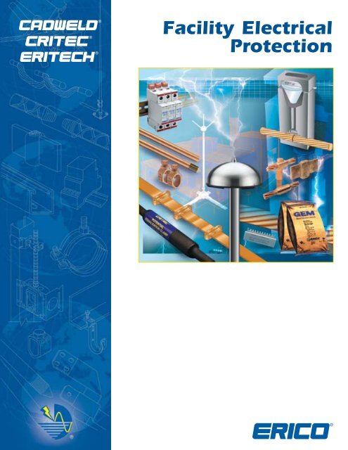
Facility Electrical Protection
Facility Electrical Protection
Facility Electrical Protection

Create successful ePaper yourself
Turn your PDF publications into a flip-book with our unique Google optimized e-Paper software.
<strong>Facility</strong> <strong>Electrical</strong><br />
<strong>Protection</strong>
FACILITY ELECTRICAL PROTECTION<br />
Founded in 1903 as the Electric Railway Improvement Company, ERICO developed the CADWELD ®<br />
exothermic welding process in 1938. CADWELD connections have found industry-wide acceptance as the ultimate<br />
grounding and bonding connection. During the 1970s, ERICO pioneered the copperbonded steel ground rod electrode.<br />
Today, ERICO’s range of facility electrical protection products includes ERITECH ® ground rods, clamps, grounding and<br />
bonding assemblies, ground enhancement material, ground testers, structural lightning protection, equipotential mesh<br />
and mats, and signal reference grids; CRITEC ® low-voltage TVSS devices; and CADWELD ® exothermic connections.<br />
<strong>Facility</strong> <strong>Electrical</strong> <strong>Protection</strong><br />
Lightning protection, grounding, equipotential<br />
bonding and surge protection are all<br />
interdependent disciplines and the focus of our<br />
<strong>Facility</strong> <strong>Electrical</strong> <strong>Protection</strong> product group.<br />
Reliable protection of personnel and structures<br />
demands a systematic and comprehensive<br />
approach to minimizing threats caused by<br />
transients and other<br />
system disturbances. For<br />
instance, no air terminal<br />
can safely capture and<br />
arrest the lightning energy<br />
without a dependable route<br />
to ground. Equally, even the<br />
most expensive Surge<br />
<strong>Protection</strong> Device (SPD) will<br />
not provide optimum protection<br />
if a low-impedance<br />
electrical connection to the<br />
ground is not present.<br />
Additionally, a lowimpedance<br />
ground system<br />
may create hazards to<br />
equipment and personnel<br />
alike if equipotential<br />
bonding is not in place.<br />
These interdependent<br />
disciplines are best applied<br />
when looking at a total facility rather than an<br />
individual piece of equipment or a portion of the<br />
facility.<br />
Since no single technology can eliminate the<br />
harmful effects of lightning or induced-surge<br />
transients, ERICO has developed the Six Point Plan<br />
of <strong>Protection</strong>. The concept behind this plan is a<br />
holistic and coordinated approach that embraces<br />
all aspects of effective facility electrical protection.<br />
The six interdependent disciplines that form the<br />
protection plan are:<br />
1. Capture the lightning strike<br />
2. Convey this energy to ground<br />
3. Dissipate energy into the grounding system<br />
4. Bond all ground points together<br />
5. Protect incoming AC power feeders<br />
6. Protect low voltage data/telecommunications circuits<br />
At ERICO, we offer innovative,<br />
efficient grounding and bonding<br />
products as well as engineering<br />
experience and technical support.<br />
With this experience, ERICO is a<br />
world-leading authority in the design<br />
and construction of permanent,<br />
low-impedance grounding systems.<br />
ERICO employs a quality-assurance<br />
program to help ensure that detailed<br />
procedures required for every step of<br />
the operation produce the best<br />
possible system for our clients. This<br />
attention to detail includes design,<br />
materials procurement, manufacturing,<br />
installation and testing.<br />
Our research and development<br />
capabilities provide continuous<br />
design improvement with new and improved products<br />
that preempt the challenging requirements of everevolving<br />
industry applications. Engineering expertise is<br />
shared among the other ERICO operations worldwide,<br />
to provide a comprehensive global knowledge pool.<br />
Trust ERICO for all of your facility electrical<br />
protection needs.<br />
www.erico.com
FACILITY ELECTRICAL PROTECTION<br />
Table of Contents<br />
Technical Information ..................................................................................Pages 4-16<br />
ERITECH ® Lightning <strong>Protection</strong>............................................................Pages 17-26<br />
ERITECH ® Conductors ................................................................................Pages 27-29<br />
ERITECH ® Grounding and Bonding ..................................................Pages 30-41<br />
CRITEC ® Surge <strong>Protection</strong> ........................................................................Pages 42-44<br />
CADWELD ® /CADWELD ® PLUS/CADWELD ® MULTI ..................Pages 45-56<br />
Index ......................................................................................................................Pages 57-59<br />
www.erico.com<br />
1
CATALOGUE OVERVIEW<br />
LIGHTNING PROTECTION<br />
Point 1 - Capture the<br />
lightning strike<br />
ERICO ® Six Point Plan of <strong>Protection</strong><br />
Effective lightning protection involves the integration<br />
of several concepts. ERICO ® employs the Six Point Plan of <strong>Protection</strong><br />
as a useful guide to ensure the highest level of system security.<br />
PAGES 17 TO 19<br />
PAGES 21 TO 22<br />
Point 2 - Convey this<br />
energy to ground<br />
PAGES 23 TO 26<br />
GROUNDING & BONDING<br />
Point 3 - Dissipate energy into<br />
the grounding system<br />
Point 4 - Bond all ground<br />
points together<br />
PAGES 27 TO 29<br />
PAGES 31 TO 37 PAGES 38 TO 41<br />
2 www.erico.com
CATALOGUE OVERVIEW<br />
SURGE PROTECTION<br />
Point 5 - Protect incoming AC<br />
power feeders<br />
1<br />
2<br />
3<br />
Capture the lightning strike. Capture the lightning<br />
strike to a known and preferred attachment<br />
point using a purpose-designed air terminal system.<br />
Convey this energy to ground. Conduct the<br />
energy to the ground via a purpose-designed<br />
downconductor.<br />
Dissipate energy into the grounding system.<br />
Dissipate energy into a low impedance<br />
grounding system.<br />
Point 6 - Protect low voltage data/<br />
telecommunications circuits<br />
Bond all ground points together. Bond all ground points to<br />
help eliminate ground loops and create an equipotential plane.<br />
CADWELD ® PLUS<br />
PAGES 46 TO 48<br />
CADWELD ®<br />
PAGES 48 TO 56<br />
CADWELD ® MULTI<br />
PAGES 43 TO 44 PAGES 43 TO 44 PAGE 49<br />
4<br />
5<br />
6<br />
Protect incoming AC power feeders. Protect equipment from<br />
surges and transients on incoming power lines to help prevent<br />
equipment damage and costly operational downtime.<br />
Protect low voltage data/telecommunications circuits.<br />
Protect equipment from surges and transients on incoming<br />
telecommunications and signal lines to help prevent equipment<br />
damage and costly operational downtime.<br />
NEW<br />
CADWELD SURGE PROTECTION GROUNDING & BONDING CONDUCTORS LIGHTNING PROTECTION TECHNICAL INFORMATION<br />
www.erico.com<br />
3
TECHNICAL INFORMATION<br />
TECHNICAL INFORMATION<br />
ERITECH ® SYSTEM 3000<br />
PROTECTION OF STRUCTURES<br />
AGAINST LIGHTNING<br />
There are 2 types of devices for the protection of structures against<br />
lightning: the conventional one, based only on passive components<br />
(copper, galvanized steel...), and the active protection system, The<br />
latter being based on advanced knowledge and more than 15<br />
years of experience.<br />
ACTIVE PROTECTION<br />
WHAT IS THE SYSTEM?<br />
The ERITECH ® SYSTEM 3000 is a technically advanced lightningprotection<br />
system. The unique features of this system allow the<br />
achievement of superior technical performance and hence provide<br />
more reliable lightning capture.<br />
The ERITECH ® DYNASPHERE air terminal provides a preferred point for<br />
lightning discharges which would otherwise strike and damage an<br />
unprotected structure and/or its contents. The ERITECH DYNASPHERE<br />
is connected to an ERITECH ® ERICORE downconductor and the ground<br />
system in such a way as to provide a totally integrated system.<br />
PROTECTION LEVEL<br />
Lightning is a statistical phenomena where 100% protection is virtually<br />
impossible to achieve, and certainly, is not economically practical. IEC<br />
62305-3 defines 4 protection levels together with associated interception<br />
efficiencies. This information is used to determine the appropriate air<br />
terminal location and spacing.<br />
LEVEL I 99% Very high risk structures<br />
LEVEL II 97% High risk structures<br />
LEVEL III 91% Medium risk structures<br />
LEVEL IV 84% Low risk structures, e.g. Residential<br />
AIR TERMINAL<br />
THE ERITECH DYNASPHERE<br />
ENHANCED AIR TERMINAL<br />
The patented ERITECH DYNASPHERE is an enhanced air terminal.<br />
• Non radioactive<br />
• Not externally powered<br />
• Has no moving parts<br />
• Responds dynamically to the approach of a lightning downleader.<br />
PRINCIPLES OF THE ERITECH DYNASPHERE<br />
For more than 200 years little improvement was made in lightning protection<br />
systems.<br />
Modern research and recording methods have led to a better understanding<br />
of the lightning discharge process and various breakthroughs have<br />
been achieved in the simulation of lightning electric-field conditions.<br />
Two fundamental concepts have emerged from recent research into<br />
the lightning attachment process and air terminal performance:<br />
1. Air terminals that produce copious quantities of corona (space charge)<br />
are likely to be less efficient in the interception of a lightning<br />
downward leader.<br />
2. An optimum air terminal is one which launches an upward streamer<br />
when it is highly likely to convert into a stable, propagating leader<br />
(to intercept the downward leader)<br />
The ERITECH DYNASPHERE has been developed with these two<br />
concepts in mind.<br />
The ERITECH DYNASPHERE is an enhanced Franklin rod with a<br />
spherical dome which is capacitively coupled to the electric field of an<br />
approaching lightning downleader.<br />
This spherical conductive surface surrounds a central earthed lightning<br />
rod. The sphere is insulated from the rod but connected to ground via<br />
a high impedance with DC conduction.<br />
The ERITECH DYNASPHERE is isolated from the structure using an insulated<br />
support mast. The mast also enables the safe connection of the<br />
ERITECH ERICORE downconductor to the air terminal.<br />
4<br />
www.erico.com
TECHNICAL INFORMATION<br />
PLASTIC FILLER TO INCREASE EFFECTIVE<br />
DIAMETER OF CORE CONDUCTOR<br />
(Inductance-Skin effect)<br />
MAIN CONDUCTOR<br />
COPPER TAPE<br />
SEMI-CONDUCTIVE STRESS CONTROL LAYER<br />
POLYETHYLENE H.V. INSULATION<br />
SEMI-CONDUCTIVE STRESS CONTROL LAYER<br />
MAIN COPPER TAPE SCREEN<br />
SEMI-CONDUCTIVE OUTER SHEATH<br />
METAL SADDLES SECURE CABLE & BOND<br />
OUTER SCREEN TO STRUCTURE<br />
TECHNICAL AND DESIGN<br />
CHARACTERISTICS<br />
OF ERITECH ® ERICORE<br />
The ERITECH ERICORE downconductors have been<br />
designed to meet the criteria for an effective and<br />
reliable downconductor with the following key<br />
characteristics:<br />
• a low inductance per unit length<br />
• a low surge impedance<br />
• a carefully controlled internal electric field distribution<br />
to minimise field stresses under current impulse<br />
conditions<br />
• carefully designed, stress reducing upper<br />
termination.<br />
TECHNICAL INFORMATION<br />
ERITECH ® SYSTEM 1000<br />
ERITECH ® INTERCEPTOR SI ESE LIGHTNING TERMINALS<br />
• Designed and tested to NFC17-102 and UNE-21186<br />
• Stainless steel design suitable for most environments<br />
• Available in three models to suit specific site requirements<br />
• Suitable for connection to a variety of downconductor systems including<br />
tape, cable, smooth-weave and ERICORE conductor<br />
• Fully compatible with the ERITECH ® SYSTEM 3000 mast, ERITECH ERICORE<br />
cable and accessories<br />
CONVENTIONAL PROTECTION<br />
Conventional protection of buildings or structures<br />
involves the use of suitably positioned air terminals<br />
(lightning rods) which are interconnected with a metal<br />
downconductor network (usually copper) to provide the<br />
most direct path from the air termination to a low<br />
impedance grounding system.<br />
This helps ensure a safe and effective dissipation of the<br />
lightning impulse. Comprehensive conventional systems<br />
are often referred to as Faraday Cages.<br />
ERITECH ® SYSTEM 2000<br />
Simple lightning rod<br />
Faraday cage<br />
www.erico.com<br />
5
TECHNICAL INFORMATION<br />
TECHNICAL INFORMATION<br />
For the efficient performance of a lightning protection system, it is<br />
essential that a low impedance ground be provided to facilitate the<br />
dissipation of the lightning energy into the earth mass.<br />
Because soil conditions and seasonal patterns vary from site to<br />
site, the methods of grounding need to be considered on an<br />
individual basis.<br />
GROUND RODS,<br />
TAPES AND CLAMPS<br />
ERITECH ® copperbonded, galvanized and stainless steel earth rods<br />
facilitate the transfer of surges and fault currents into the earth, and<br />
provide a long service life due to superior construction and quality.<br />
GROUND ENHANCEMENT<br />
MATERIAL (GEM)<br />
Ground enhancing materials can be applied around the conductors in<br />
a grounding system to reduce the local soil resistivity and lower ground<br />
impedance. They are particularly useful in areas of moisture variation,<br />
sandy soils and rocky ground.<br />
GROUND POTENTIAL<br />
EQUALISATION<br />
ERICO’s range of equipotential ground bars, plates, pre-engineered<br />
grids, and Potential Equalization Clamps combine to create a safe<br />
equipotential ground plane for the protection of personnel and equipment.<br />
CADWELD ® /CADWELD ® PLUS<br />
MOLECULAR BONDING<br />
Connections are often the most critical element of grounding<br />
systems, and subsequently can become the weak point due to<br />
ageing and corrosion. The preferred method of connection is the<br />
CADWELD ® exothermic welding process producing a molecular<br />
bond. The capacity of an earthing circuit to protect the safety of<br />
personnel depends on the quality of the connections made.<br />
Polymeric<br />
Cover<br />
CADWELD PLUS<br />
Package<br />
Graphite<br />
Mould<br />
Conductor<br />
Ignitor Strip<br />
Tap Hole<br />
Weld Cavity<br />
COVER<br />
CRUCIBLE<br />
STARTING<br />
POWDER<br />
THE CADWELD MOULD<br />
WELDING<br />
MATERIAL<br />
DISC<br />
SEAT<br />
TAP<br />
HOLE<br />
WELD<br />
CAVITY<br />
CONDUCTOR<br />
CONDUCTOR<br />
6<br />
www.erico.com
TECHNICAL INFORMATION<br />
GROUND ELECTRODES<br />
The ground electrode is a critical component of the grounding<br />
system. Many different types of electrodes are available, some<br />
"natural" and some "made”. The natural types include metal<br />
underground water pipe, the metal frame of a building (if effectively<br />
grounded), a copper wire or reinforcing bar in a concrete foundation<br />
or underground structures or systems. Consideration should be<br />
given to bonding of natural earths to ensure electrical continuity<br />
with a facilities’ other "earths".<br />
"Made" electrodes are specifically installed to improve the system<br />
grounding or earthing. These earth electrodes must ideally penetrate<br />
into the moisture level below the ground level to reduce resistance.<br />
They must also consist of metal conductors (or a combination of<br />
metal conductor types), which do not corrode excessively for the<br />
period of time they are expected to serve. Made electrodes include<br />
rods or pipes driven into the earth, metallic plates buried in the earth<br />
or a copper wire ring encircling the structure. Underground gas<br />
piping or aluminium electrodes are NOT permitted for use as ground<br />
electrodes.<br />
TECHNICAL INFORMATION<br />
GROUND RODS<br />
Which ground rod should be used?<br />
Ground rods are often selected on the basis of their resistance to corrosion.<br />
The other major factor is cost. All too often, the cost of a product is seen as<br />
the initial up front price, but the real cost is determined by the serviceable life<br />
of the ground rod.<br />
Galvanized steel rods are one of the cheapest electrodes available. However,<br />
they are not the most cost effective since they have a relatively short service<br />
life. Solid copper and stainless steel rods have a long service life. However,<br />
they are considerably more expensive than galvanized steel rods. In addition to<br />
this, solid copper rods are not suited to deep driving or even driving short<br />
lengths into hard ground, without bending.<br />
As a compromise, steel cored ground rods,<br />
swaged in a copper or stainless steel<br />
sheath were developed. These ground<br />
rods are much less expensive than their<br />
solid counterparts. They are capable of<br />
being deep driven. However, the sheath<br />
of this rod type has been known to slip<br />
or tear, particularly the copper version. Once<br />
this sheath has been damaged, the integrity<br />
of the entire electrode is at risk.<br />
Ask for the ERICO ® White Paper on Ground Rods –<br />
Copperbonded vs. Galvanized.<br />
Copperbonded ground rod<br />
versus Galvanized ground rod.<br />
COPPERBONDED<br />
GROUND ROD<br />
• Cost effective<br />
long service life<br />
Copperbonded<br />
coating:<br />
• Permanent<br />
molecular bond<br />
• Low resistance<br />
performance<br />
• High fault current<br />
capacity (IEEE ® Std 80)<br />
• Will not slip or tear<br />
when driven<br />
• Will not crack<br />
if rod is bent<br />
Carbon Steel<br />
core and tip:<br />
• Greater tensile<br />
strength<br />
• Deep driving<br />
capability<br />
GALVANIZED<br />
GROUND ROD<br />
• Lower purchase<br />
price - not as cost<br />
effective as<br />
Copperbonded<br />
Galvanized coating:<br />
• Relatively short<br />
service life<br />
• May crack if rod<br />
is bent<br />
Steel core and tip:<br />
• High tensile<br />
strength<br />
• Deep driving<br />
capability<br />
www.erico.com<br />
7
TECHNICAL INFORMATION<br />
TECHNICAL INFORMATION<br />
GROUND ELECTRODES<br />
The copperbonded ground rod has an<br />
electrolytic coating of copper deposited<br />
over a layer of nickel. This process<br />
ensures a long lasting, molecular bond<br />
between the copper layer and the steel<br />
core. ERICO ® recommends<br />
copperbonded ground rods because<br />
the copper coating will not slip or tear<br />
when driven nor will it crack if the rod<br />
is bent. The tough, carbon steel core<br />
has good characteristics for deep<br />
driving. Copperbonded ground rods<br />
have a high resistance to corrosion and<br />
provide a low resistance path to<br />
ground.<br />
Above photo shows two ground rods<br />
subjected to the same pressure load test.<br />
The ERITECH ® copperbonded ground rod,<br />
shown on the left, will bend without tears,<br />
cracks or folds, to the outer sheath. The<br />
inferior copperclad rod shown on the right,<br />
has developed cracks and creases to the<br />
outer sheath, which will significantly<br />
reduce its serviceable life and put the<br />
integrity of the entire electrode at risk.<br />
The Stainless Steel Option<br />
It is important to note that certain soils<br />
and land fill areas may not be compatible<br />
with copper. In these situations, stainless<br />
steel is a better proposition. Stainless<br />
steel may also be an alternative, where<br />
structures or components, such as steel<br />
towers, poles or lead sheathed cables are<br />
in close proximity to an array of ground<br />
electrodes. In these circumstances,<br />
consideration must be given to the<br />
consequence of galvanic corrosion. The<br />
high cost of stainless steel rods prohibits<br />
their widespread use.<br />
GROUND ROD LIFE EXPECTANCY<br />
GROUND ROD ANNUAL COST<br />
YEARS<br />
COMPARATIVE COST<br />
Zinc<br />
Galvanized<br />
Copperbonded<br />
Steel (10 mil/254μm)<br />
Copperbonded<br />
Steel (13 mil/330μm)<br />
Stainless<br />
Steel<br />
Zinc<br />
Galvanized<br />
Copperbonded<br />
Steel (10 mil/254μm)<br />
Copperbonded<br />
Steel (13 mil/330μm)<br />
Stainless<br />
Steel<br />
8<br />
www.erico.com
TECHNICAL INFORMATION<br />
WHY IS GOOD GROUNDING IMPORTANT?<br />
The transient nature of lightning with its associated fast rise times and<br />
large magnitude currents mean that special consideration needs to be<br />
given to grounding, for lightning protection to be effective. Many<br />
factors such as soil resistivity variations, installation accessibility, layout<br />
and existing physical features are all site specific and tend to affect<br />
decisions on grounding methods employed. The primary aim of a<br />
direct strike grounding system is to:<br />
• Efficiently dissipate lightning surge energy into the ground<br />
• Help ensure safety of equipment and personnel<br />
GROUNDING PRINCIPLES<br />
Low impedance is the key to lightning protection. All grounding<br />
connections should be as short and direct as possible to minimise<br />
inductance and reduce peak voltages induced in the connections. The<br />
ground electrode system must efficiently couple lightning surges into<br />
the ground by maximising capacitive coupling to the soil. The<br />
resistance of the ground itself to lightning currents must also be<br />
minimised. Only when all these factors are taken into account will<br />
maximum lightning protection be achieved.<br />
GROUND IMPEDANCE<br />
Soil resistivity is an important design consideration. It varies markedly<br />
for different soil types, moisture content and temperatures and gives<br />
rise to variations in ground impedances.<br />
Figure 1-B illustrates current flow from the injection point of a single<br />
ground electrode. As current flows out from the central injection<br />
point, a voltage gradient on the ground surface around the electrode<br />
is produced. This gradient levels off to a plateau at some distance from<br />
the electrode, as seen in Figure 1-A. The impedance seen by the<br />
current is determined by the soil particles in direct contact with the<br />
surface of the rod, and by the general impedance of the soil.<br />
SHORT, DIRECT GROUND CONNECTIONS<br />
The voltage generated by a lightning surge depends primarily on the<br />
risetime of the surge current and the impedance (primarily inductance)<br />
of the path to ground. Extremely fast rise times result in significant<br />
voltage rises due to any series inductance resulting from long, indirect<br />
paths, or sharp bends in the routing of ground conductors.<br />
COUPLING FROM THE ELECTRODE<br />
SYSTEM TO THE GROUND<br />
The efficiency of a ground electrode system in coupling a lightning<br />
surge current to ground is dependent on a number of factors, including<br />
the geometry of the ground electrode system, the shape of the<br />
conductors and the effective coupling into the soil.<br />
Fig.1-A<br />
Fig.1-B<br />
Earth Rod<br />
CHARACTERISTICS OF A GOOD<br />
GROUNDING SYSTEM<br />
• Good electrical conductivity<br />
• Conductors capable of withstanding high fault currents<br />
• Long life - at least 40 years<br />
• Low ground resistance and impedance<br />
The basis philosophy of any grounding installation should be an<br />
attempt to maximise the surface area of electrodes or conductors with<br />
the surrounding soil. Not only does this help to lower the earth<br />
resistance of the grounding system, but it also greatly improves<br />
the impedance of the grounding system under lightning surge<br />
conditions.<br />
• Equipotential bonding<br />
Equipotential bonding helps ensure that hazardous potential differences<br />
do not occur between different incoming conductors<br />
such as metallic water services, power systems, telecommunication<br />
systems and the local ground, and also minimises step and<br />
touch potentials.<br />
• Good corrosion resistance<br />
Distance<br />
from the<br />
electrode<br />
TECHNICAL INFORMATION<br />
GEM<br />
DOWNCONDUCTOR<br />
EARTH PIT<br />
The ground electrode system should be corrosion resistant, and<br />
compatible with other conductors that are buried and bonded to<br />
the ground system. Copper is by far the most common material<br />
used for grounding conductors. In general, some form of maintenance<br />
or inspection procedure should be adopted to ensure the<br />
long-term effectiveness of a grounding system.<br />
• <strong>Electrical</strong>ly and mechanically robust and reliable<br />
A typical grounding system.<br />
www.erico.com<br />
Mechanical coupling can be used to join ground conductors, but<br />
suffers from corrosion effects when dissimilar metals are involved.<br />
As well as mechanical strength, CADWELD ® connections provide<br />
excellent low impedance, long life electrical connections with<br />
excellent corrosion resistance.<br />
9
TECHNICAL INFORMATION<br />
TECHNICAL INFORMATION<br />
COMPONENTS OF A GROUNDING<br />
SYSTEM<br />
A grounding system for lightning protection serves to deliver<br />
the lightning current into ground. It consists of one or more<br />
ground electrodes (earthing rods) along with any interconnecting<br />
conductors. Components include:<br />
WITHOUT<br />
PROTECTION<br />
WITHOUT<br />
PROTECTION<br />
• Ground rods<br />
• Ground enhancing materials<br />
• CADWELD ® exothermic welded connections<br />
• Ground connectors – tapes, stranded cables, rod clamps,<br />
mesh, plates etc<br />
• Ground pits - for access to the ground system<br />
DESIGNING A GROUND ELECTRODE SYSTEM<br />
A significant factor governing the choice of a grounding system are<br />
the applicable standards and codes:<br />
European IEC 10234-1, IEC 61364-5, ENV 61024-1,<br />
BS 1400, BS 7430, NFC 17100, NFC 17102<br />
EN-50164-2<br />
American NFPA ® 780, IEEE ® STD80, IEEE 837, NFPA 70<br />
Australian AS1768<br />
Other factors to consider include:<br />
• The needs and layout of the facility<br />
(location and space confinement issues)<br />
• The ground environment of the facility itself<br />
(eg soil resistivity)<br />
• Existing grounding systems<br />
• Susceptibility to seasonal variations in soil moisture<br />
content and temperature<br />
• Exposure to pedestrian traffic<br />
• Step and Touch Potentials<br />
While it is clear that a low impedance grounding system will allow the<br />
lightning surge energy to be dissipated into the ground, this will not<br />
necessarily minimise hazards to personnel in close proximity to the<br />
grounding system. High voltage gradients on the surface of the<br />
ground give rise to undesirable step and touch potential hazards. In<br />
order to reduce the chance of injury to personnel, both step and touch<br />
potentials must be minimised. Figure 2 graphically illustrates the<br />
danger of such potentials.<br />
• Selecting the right connections<br />
The connections between the conductors and the main grid, and<br />
between the grid and ground rods, are as important as the conductors<br />
themselves in maintaining a permanent low-resistance path to ground.<br />
Figure 2<br />
DIFFERENCE OF<br />
POTENTIAL<br />
Step and Touch Potential. Step potential is the voltage difference between a<br />
person’s feet caused by the dissipation gradient of a fault entering the earth.<br />
Touch potential is similar to “step potential” except that the fault current passes<br />
through the person’s arm and torso on the way to the ground.<br />
• Reducing ground impedance<br />
Resistivity of the soil varies markedly for different soil types, moisture<br />
content and temperatures, and this gives rise to variations in ground<br />
system impedance. The lower the resistivity, the easier it is to achieve<br />
an effective grounding system. Measures that can be used for reducing<br />
earth impedance include:<br />
• Connecting additional buried conductors to the ground electrode<br />
• Use of multiple interconnected ground electrodes<br />
• Use of flat tape rather than circular conductors<br />
• Use of spaced conductors connected in parallel<br />
• Use of equipotential mesh electrodes<br />
• Use of multiple short interconnected buried conductor<br />
• Use of ground enhancing compounds<br />
<strong>Electrical</strong>ly conductive ground enhancing compounds can be applied<br />
to help lower ground resistance and impedance. They are particularly<br />
useful for rocky ground, areas of moisture variation and sandy soils.<br />
These compounds are generally applied around electrodes in oversized<br />
drill holes and around horizontal buried conductors.<br />
• Use of mineral or chemical ground rods<br />
Mineral or chemical ground rods are also used to decrease ground<br />
impedance. These consist of a perforated hollow copper tube sealed<br />
at the bottom. A salt compound is placed inside the tube which<br />
gradually leaches out to maintain a conductive environment around<br />
the electrode.<br />
• Use of concrete slabs or footings<br />
The use of reinforced concrete slabs and footings is one of the most<br />
effective ways to provide a low impedance ground electrode system. If<br />
addressed at the design stage this method can provide a very stable,<br />
permanent distributed ground electrode system at very little additional<br />
cost to the civil works.<br />
10<br />
www.erico.com
TECHNICAL INFORMATION<br />
GROUND POTENTIAL EQUALISATION<br />
Creating an equipotential earth plane under transient conditions is<br />
essential for equipment and personnel safety. However, separate earths<br />
are sometimes installed for lightning, mains power, computer and<br />
communications equipment in buildings and other installations.<br />
Although this may be desirable under normal operating conditions,<br />
when lightning or other transient voltages occur, potential differences<br />
between the separate earths are inevitable. These can enter buildings,<br />
destroying equipment and creating dangers for personnel.<br />
TECHNICAL INFORMATION<br />
The PEC (Potential Equalization<br />
Clamp) usually operates as an<br />
effective open circuit. However,<br />
once the earth potential difference<br />
exceeds the breakdown voltage<br />
of the PEC (under transient<br />
conditions), the circuit closes<br />
immediately and the earth<br />
potential’s are equalised, thereby<br />
protecting equipment and people.<br />
GROUND ENHANCEMENT MATERIAL (GEM)<br />
A superior conductive material that improves grounding effectiveness,<br />
especially in areas of poor conductivity (rocky ground, areas of<br />
moisture variation, sandy soils) :<br />
Estimated linear feet of ground conductor covering<br />
with each bag of GEM<br />
TELECOM<br />
EARTH<br />
BAR<br />
POWER<br />
EARTH<br />
BAR<br />
MAINS<br />
POWER<br />
EARTH<br />
WIRE<br />
LIGHTNING<br />
DOWNCONDUCTOR<br />
Trench<br />
Width<br />
Total thickness of GEM<br />
2, 5 cm 5, 1 cm 7, 6 cm 10, 2 cm<br />
(1”) (2”) (3”) (4”)<br />
EARTH<br />
PIT<br />
10 cm (4”) 4.3 m (14.0’) 2.1 m (7.0’) 1.4 m (4.7’) 1.1 m (3.5’)<br />
15 cm (6”) 2.8 m (9.3’) 1.4 m (4.7’) 0.9 m (3.1’) 0.7 m (2.3’)<br />
20 cm (8”) 2.1 m (7.0’) 1.1 m (3.5’) 0.7 m (2.3’) 0.5 m (1.8’)<br />
25 cm (10”) 1.7 m (5.6’) 0.9 m (2.8’) 0.6 m (1.9’) 0.4 m (1.4’)<br />
30 cm (12”) 1.4 m (4.7’) 0.7 m (2.3’) 0.5 m (1.6’) 0.4 m (1.2’)<br />
TELECOM EARTH MAINS EARTH LP EARTH<br />
Equipotential earth plane created by bonding all earths<br />
together with Potential Equalization Clamps (PEC).<br />
• Appropriate depth and separation of electrodes<br />
The length, number and placement of ground rods affects the resistivity<br />
of the path to ground. The most cost-effective depth to which an electrode<br />
should be driven is usually dependent on specific soil conditions. Soils<br />
are rarely homogeneous or uniform and it may be advantageous to<br />
install electrodes to a particular depth where a low resistivity soil layer,<br />
such as a clay base, is encountered. Electrode depths commonly used<br />
are in the range of 1 to 4 m. Electrodes should be separated by a<br />
distance of at least twice the depth to which they are installed.<br />
• Equipotential Bonding<br />
Potential equalisation ensures that any potential rise due to the injection<br />
of lightning current into the impedance of the grounding network, is<br />
experienced by all the conductive services in the building. Thus everything<br />
rises in potential together and hazardous potential differences are avoided.<br />
Estimated bags of GEM for backfilling around ground<br />
rods to a density of 90 lb/cu ft (1442 kg/m3)<br />
Dia. of<br />
hole<br />
Depth of hole (Feet) *<br />
1.8 m 2.1 m 2.4 m 2.7 m 5.2 m 5.8 m 6.1 m<br />
(6’) (7’) (8’) (9’) (17’) (19’) (20’)<br />
7.5 cm (3”) 2 2 2 2 4 4 4<br />
10.0 cm (4”) 2 3 3 3 6 7 7<br />
12.5 cm (5”) 3 4 4 5 9 10 10<br />
15.0 cm (6”) 5 5 6 7 13 14 15<br />
17.5 cm (7”) 6 7 8 9 17 19 20<br />
20.0 cm (8”) 8 9 11 12 22 25 26<br />
22.5 cm (9”) 10 12 13 15 28 31 32<br />
25.0 cm (10”) 12 14 16 18 34 38 40<br />
www.erico.com<br />
11
TECHNICAL INFORMATION<br />
TECHNICAL INFORMATION<br />
PROTECTION FROM POWER SURGES<br />
To meet the fundamental requirements of performance, longer service life and greater safety under real world conditions, ERICO ® has<br />
developed a range of technologies covering all aspects of the Six Point Plan of <strong>Protection</strong>. In the field of surge protection, several<br />
technologies play a critical role in the provision of premium performance.<br />
The DINLINE Product range offers both shunt or series protection utilising differing technologies in compact DIN rail mounted products.<br />
A number of different options are available to suit your individual application or performance requirements.<br />
SHUNT SURGE PROTECTION DEVICES<br />
SERIES SURGE PROTECTION DEVICES<br />
For strategic or critical applications the DINLINE Surge Filter<br />
(DSF/TDF) provides, superior protection for sensitive electronic<br />
equipment. In addition to simply diverting the surge energy, the<br />
units filter the clamped waveform. The products should be<br />
installed prior to sensitive and valuable electronic equipment<br />
and installations utilising electronic and communications<br />
systems.<br />
Shunt Surge protection devices alone do not help modify the<br />
excessive wavefront characteristics of lightning. The high rate<br />
of current rise (dI/dt) and the rate of induced voltage rise (dV/dt)<br />
are properties of the lightning waveform which are often the<br />
principle causes of damage to sensitive electronic components<br />
and equipment.<br />
The DINLINE Surge Diverters (DSD) offer economical and reliable protection<br />
from transients on power lines with the convenience of easy<br />
installation on 35 mm DIN rail mountings.<br />
The DSF and TDF product range is therefore designed to provide<br />
suitable low pass filter technologies that act to limit and slow<br />
down the Output Voltage (or Let-through voltage under surge<br />
conditions). The figure below illustrates the fundamental<br />
performance difference between the DSD and DSF/TDF product<br />
lines under surge conditions.<br />
The DSD range includes the three phase DSD340 series for<br />
simple installation into TN-C, TN-S and TT systems.<br />
Alternatively multiple DSD1x units may be configured for<br />
TN-C, TN-S, TN-C-S, TT & IT systems with surge ratings ranging<br />
form 10kA to 150kA.<br />
TEST<br />
WAVEFORM<br />
OPEN CIRCUIT<br />
CLOSED CIRCUIT<br />
OUTPUT VOLTAGE (Volts)<br />
Internal thermal disconnect devices ensure safe isolation<br />
during sustained and abnormal events on the distribution<br />
network. Most units feature visual indication in the event of<br />
such operation. In addition, select units are available with<br />
voltage-free contacts for remote signaling if replacement is due.<br />
DSD SHUNT-ONLY PROTECTOR<br />
TIME (μs)<br />
DSF/TDF SURGE FILTER<br />
12<br />
www.erico.com
TECHNICAL INFORMATION<br />
PROTECTION OF COMMUNICATIONS EQUIPMENT<br />
Transients and surges caused by lightning, or switching of power equipment, affect communications signals carried on copper<br />
cables. Telecommunications lines, industrial process control, coaxial feeders and computer networks are all vulnerable to surges,<br />
which may be up to 20kA for some high-risk environments. In the field of communications surge protection, several product<br />
variations are required to ensure all applications are met. Therefore ERICO ® offers protection products to meet a wide variety of<br />
applications, from telecommunication line protectors for either KRONE ® or DIN connection to coaxial surge protectors suitable for<br />
either BNC or N type coax cables.<br />
TECHNICAL INFORMATION<br />
The various product families and applications are summarised below:<br />
Subscriber Line<br />
<strong>Protection</strong> (SLP) and<br />
High Speed Digital<br />
<strong>Protection</strong> (HSP)<br />
Product family<br />
- High 20kA (8/20us)<br />
surge rating<br />
- KRONE LSA-Plus<br />
Termination<br />
- Both Single Stage<br />
and Multi-Stage<br />
models available<br />
Universal Transient<br />
Barrier (UTB)<br />
- High 20kA (8/20us)<br />
surge rating<br />
- Premium three<br />
stage protection<br />
- Self-resetting,<br />
over-voltage and<br />
over-current protection<br />
Co-axial Surge<br />
Protectors (CSP)<br />
- Robust, plug-in style<br />
design<br />
- Range of connections<br />
types and operating<br />
voltages available<br />
- Wide operating<br />
frequency from DC<br />
up to 3GHz<br />
Data Line Protectors<br />
(DLP) / Data Equipment<br />
Protectors (DEP) / Local<br />
Area Network<br />
Protectors (LAN)<br />
- Range of connections<br />
types available, from<br />
DB to RJ45 and KRONE<br />
- Wide range of operating<br />
voltages and frequencies<br />
available<br />
- Surge Ratings from<br />
500A to 20kA<br />
depending on product<br />
and application<br />
Knowing where to install surge protection can be difficult. To<br />
ensure cost-effective protection is provided for data, signaling<br />
and control circuits, two issues need to be considered:<br />
WHAT TYPE OF SPD IS APPROPRIATE FOR<br />
EACH CIRCUIT TYPE AND LOCATION ?<br />
Five parameters must be considered to ensure that surge<br />
protection devices for use on data, signalling or control circuits<br />
are suitable and do not adversely affect operation of the circuit.<br />
1) SPDs are designed to clamp the excess transient voltage to<br />
safe levels sustainable by the equipment, yet should not<br />
interfere with the normal signalling voltages. As a guide, the<br />
SPD clamping voltage should be selected to be approximately<br />
20% higher than peak working voltage of the circuit.<br />
2) The line current rating of the SPD should be sufficient to<br />
handle the maximum expected signalling current.<br />
3) The SPD bandwidth should be sufficient to allow<br />
correct operation of the system without adverse<br />
attenuation. For most SPDs, frequency attenuation data or<br />
a maximum recommended baud rate is generally specified.<br />
4) The connection termination, mounting method, number of<br />
lines to be protected and other physical aspects must be considered.<br />
5) The SPD surge rating should be appropriate for the<br />
intended location. For circuits internal to the building,<br />
surge ratings of 1-5kA are generally sufficient. For the<br />
protection of circuits that connect to exposed lines<br />
entering or exiting the facility, 10-20kA is recommended.<br />
WHERE SHOULD THE SPDs BE INSTALLED ?<br />
Communications devices are at risk from transients being induced<br />
onto the interconnecting signal lines. The use of surge protection<br />
barriers, installed at either end of the lines, provides cost<br />
effective mitigation. Communication or signal lines that enter<br />
or exit the building pose the highest risk. In such circumstances,<br />
protection devices should be installed at the point of entry or at<br />
the equipment termination itself.<br />
www.erico.com<br />
13
TECHNICAL INFORMATION<br />
TECHNICAL INFORMATION<br />
CADWELD ® /CADWELD ® PLUS<br />
THE MOLECULAR BOND<br />
CADWELD ® EXOTHERMIC CONNECTION<br />
A welding process that eliminates the<br />
connection by forming a molecular bond.<br />
Connections are the weak point of all electrical circuits and especially<br />
earthing circuits subjected to ageing and corrosion. The capacity of an<br />
earthing circuit to protect the safety of personnel depends on the quality of<br />
the connections made.<br />
BS 6651 (1992) STATES :<br />
"Any joint other than welded represents a discontinuity in the current<br />
conducting system and is susceptible to variation and failure.”<br />
THE CADWELD ® PROCESS<br />
The CADWELD ® process provides a way to produce copper/copper,<br />
copper/galvanized or plain steel, copper/copper clad steel,<br />
copper/bronze/brass/stainless steel, steel/steel, molecular bonds with<br />
no external energy or heat source.<br />
The principle consists of bringing together a welding filler material and<br />
ignition agent in a suitable graphite mould.<br />
The reduction of copper oxide by aluminium produces molten copper<br />
and aluminium oxide slag at extremely high temperatures.<br />
The shape of the mould, its dimensions, and the size of the weldmetal,<br />
are all dependent on the items to be welded and their size.<br />
Installation Is Easy!<br />
4 Simple Steps For Permanently Welded<br />
<strong>Electrical</strong> Connections<br />
CADWELD PLUS Control Unit initiates the reaction of<br />
the metal crucible. The standard unit includes a 6-foot (1.8<br />
meter) high temperature control unit lead. The lead attaches to<br />
the ignition strip using a custom made, purpose-designed<br />
termination clip.<br />
After the termination clip is installed on the ignition strip, the<br />
installer pushes and holds the ignition button to start a charging<br />
and discharging sequence. Within a few seconds the control<br />
unit sends a predetermined voltage to the ignition strip and the<br />
reaction is initiated.<br />
THE CADWELD ® MOULD<br />
USING CADWELD PLUS<br />
Polymeric<br />
Cover<br />
CADWELD PLUS<br />
Package<br />
Graphite<br />
Mould<br />
Conductor<br />
1 2<br />
Insert CADWELD PLUS<br />
package into mould<br />
3 4<br />
Attach control unit<br />
termination clip to<br />
ignition strip<br />
Ignitor Strip<br />
Tap Hole<br />
Weld Cavity<br />
Press and hold control<br />
unit switch and wait for<br />
the ignition<br />
Open the mould and<br />
remove the expended<br />
steel cup – no special<br />
disposal required<br />
14<br />
www.erico.com
TECHNICAL INFORMATION<br />
THE CADWELD ® WELD<br />
• Will carry more current than the conductor.<br />
• Will not deteriorate with age.<br />
• Is a molecular bond that eliminates any risk of<br />
loosening or corrosion.<br />
• Will resist repeated fault currents<br />
• Can be quality controlled simply by visual<br />
inspection.<br />
TECHNICAL INFORMATION<br />
RELIABILITY<br />
As the molecular bond eliminates the concept<br />
of surface contact, an electrolyte cannot penetrate<br />
between the conductors and cause oxidation and<br />
deterioration in the course of time.<br />
CORROSIVE ENVIRONMENTS<br />
This reliability is of particular interest for humid<br />
or chemical environments or for<br />
bonds directly buried in the ground.<br />
ABILITY TO WITHSTAND HIGH<br />
CURRENT<br />
The melting temperature of CADWELD filler<br />
material is higher than the melting temperature of<br />
copper (1082°C). For this reason, in the event<br />
of abnormal heating due to a high fault<br />
current, the conductor is destroyed before the<br />
connection.<br />
CONDUCTIVITY<br />
The CADWELD connections form a solid bond<br />
around the conductors assuring continuity. The<br />
cross sectional area of the weld has greater<br />
current carrying capacity than the conductors.<br />
CORROSION TEST<br />
This accelerated ageing test, carried out<br />
in a saline atmosphere at a controlled<br />
temperature, demonstrates that<br />
CADWELD ® welds retain all their<br />
electrical properties during the period<br />
of the test whereas the resistance of<br />
mechanical connections increase with<br />
time and this alters their conductive<br />
properties.<br />
CADWELD'S fine performance is due<br />
to its reliability resulting from the<br />
molecular bond.<br />
Comparison between CADWELD<br />
Bonded Connection and Mechanical<br />
Connection CADWELD Weld (Metal A)<br />
(Metal B).<br />
The CADWELD bonded connection provides permanent conductivity over the<br />
whole of the section due to molecular bonding between the metal surfaces.<br />
RELATIVE RESISTANCE<br />
SET CABLE/CABLE<br />
2 SAMPLES<br />
MECHANICAL<br />
2 SAMPLES<br />
SET<br />
CABLE/CABLE<br />
4 SAMPLES<br />
END 4 SAMPLES CADWELD<br />
CABLE/CABLE<br />
3 SAMPLES<br />
CADWELD<br />
TIME IN YEARS<br />
PERFORMANCE<br />
Standard CADWELD welds have a cross<br />
section greater than that of the conductors<br />
to be joined, which compensates for the<br />
difference in resistivity between the<br />
conductor and the weld material.<br />
Consequently, under fault conditions the<br />
weld will always remain cooler than the<br />
conductor.<br />
If special applications do not allow for the<br />
required increase in cross section to be<br />
employed, the use of the formula:<br />
R = p x l and V= R x l<br />
S<br />
will make it possible to define precisely the<br />
resistance of the CADWELD ® weld.<br />
Comparison between CADWELD ® Bonded Connection and Mechanical Connection<br />
CADWELD WELD<br />
(Metal A)<br />
(Metal B)<br />
The CADWELD bonded connection provides<br />
permanent conductivity over the whole of<br />
the section due to molecular bonding<br />
between the metal surfaces.<br />
MECHANICAL<br />
CRIMPED CONNECTION<br />
Line of current<br />
Actual Contact Surface<br />
The mechanical connection presents a significant<br />
difference between the apparent contact surface<br />
and the actual surface.<br />
www.erico.com<br />
15
TECHNICAL INFORMATION<br />
TECHNICAL INFORMATION<br />
Nominal Wire Size ERICO CADWELD Number Nominal Nominal Nominal Nominal Nominal<br />
Cross Mould Reference of Strands Diameter of Cable Cable Strand Wire Cross<br />
AWG Sectional Strands Diameter Diameter Area Sectional<br />
Area (mm 2 ) (mm) (mm) (inch) (mm 2 ) Area (mm 2 )<br />
#10 1B 7 0.98 2.95 0.12 0.75 5.26<br />
6 A7 7 1.04 3.12 0.12 0.85 5.95<br />
#8 1E 7 1.23 3.71 0.15 1.19 8.32<br />
10 W2 7 1.35 4.05 0.16 1.43 10.02<br />
#6 1H 7 1.55 4.67 0.18 1.89 13.21<br />
16 W3 7 1.70 5.10 0.20 2.27 15.89<br />
#4 1L 7 1.96 5.89 0.23 3.02 21.12<br />
25 Y1 7 2.14 6.42 0.25 3.60 25.18<br />
#3 1Q 7 2.20 6.60 0.26 3.80 26.61<br />
25 Y1 19 1.35 6.75 0.27 1.43 27.20<br />
#2 1V 7 2.47 7.42 0.29 4.79 33.54<br />
#2 Solid 1T 1 6.54 6.54 0.26 33.62 33.62<br />
35 Y2 19 1.53 7.65 0.30 1.84 34.93<br />
#1 1Y 19 1.50 8.43 0.33 1.77 33.58<br />
#1 Solid 1X 1 7.35 7.35 0.29 42.41 42.41<br />
50 Y3 19 1.78 8.90 0.35 2.49 47.28<br />
1/0 Solid 2B 1 8.25 8.25 0.32 53.49 53.49<br />
1/0 2C 19 1.89 9.46 0.07 2.81 53.43<br />
2/0 Solid 2F 1 9.27 9.27 0.36 67.43 67.43<br />
2/0 2G 19 2.13 10.65 0.42 3.56 67.70<br />
70 Y4 19 2.14 10.70 0.42 3.60 68.34<br />
95 Y5 37 1.78 12.46 0.49 2.49 92.07<br />
95 Y5 19 2.52 12.60 0.50 4.99 94.76<br />
3/0 2L 19 2.59 12.95 0.47 5.27 100.10<br />
4/0 Solid 2P 1 11.68 11.68 0.46 107.22 107.22<br />
4/0 2Q 19 2.89 13.41 0.53 6.56 124.63<br />
120 Y6 37 2.03 14.21 0.56 3.24 119.75<br />
250 KCM 2V 37 2.07 14.61 0.58 3.37 124.52<br />
150 Y7 37 2.25 15.75 0.62 3.98 147.11<br />
300 KCM 3A 37 2.29 16.00 0.63 4.12 152.39<br />
350 KCM 3D 37 2.47 17.30 0.68 4.79 177.29<br />
185 Y8 37 2.52 17.64 0.69 4.99 184.54<br />
400 KCM 3H 37 2.64 18.49 0.73 5.47 202.53<br />
240 Y9 61 2.25 20.25 0.80 3.98 242.54<br />
500 KCM 3Q 61 2.30 20.65 0.81 4.15 253.44<br />
300 Y0 61 2.52 22.68 0.89 4.99 304.24<br />
KCM was previously MCM, ie 1000 circular mils, a measure of the wire cross-sectional area.<br />
Note that KCM "overstates" the true cross sectional area (measured in sq. mils) of a conductor by 4/π (i.e. 1.273)<br />
1 mil = 0.001 inch<br />
Square Inches x 1273 = KCM<br />
Square Millimeters x 1.974 = KCM<br />
KCM x 0.5607 = Square Millimeters<br />
16<br />
www.erico.com
ERITECH ® LIGHTNING PROTECTION<br />
ERITECH ® SYSTEM 3000 ERITECH ® SYSTEM 1000<br />
CLT Terminal<br />
FRP Insulated Mast<br />
Inline Coupling<br />
Support Mast<br />
ERITECH ® ERICORE<br />
Insulated Downconductor<br />
ESE Terminal<br />
Metallic Mast<br />
Bare Downconductor<br />
1 or 2 Required<br />
LIGHTNING PROTECTION<br />
The ERITECH ® SYSTEM 3000 is a technically advanced lightning<br />
protection system. The unique Collection Volume Method<br />
design (CVM), and features of this system allow the<br />
achievement of superior technical performance, and hence more<br />
reliable lightning capture.<br />
The ERITECH ® DYNASPHERE air terminal provides a preferred<br />
point for lightning discharges which would otherwise strike and<br />
damage an unprotected structure and/or its contents. The<br />
ERITECH DYNASPHERE is connected to a single insulated downconductor<br />
(ERITECH ERICORE) and the ground system in such a<br />
way as to provide a totally integrated system.<br />
The ERITECH ® SYSTEM 1000 SI Interceptor terminal is designed<br />
and tested to the French Standard NFC17-102 and Spanish norm<br />
UNE-21186. For applications up to 65 m tall, these standards<br />
provide simple placement rules and determination of protected<br />
area.<br />
The terminals are erected with conductive masts and dependant<br />
upon structure height and terminal location one or two bare<br />
downconductors are required.<br />
www.erico.com<br />
17
ERITECH ® LIGHTNING PROTECTION<br />
LIGHTNING PROTECTION<br />
ERITECH ® SYSTEM 3000<br />
ERITECH ® DYNASPHERE AIR TERMINAL<br />
702085 702089<br />
Reference code Part No. Description<br />
Unit<br />
weight kg<br />
D/SMKIV-SS 702085 ERITECH ® DYNASPHERE 1 5<br />
INTMKIV-SS 702089 ERITECH ® INTERCEPTOR 1 2<br />
INLINE COUPLING<br />
Ø 70 mm<br />
Reference code<br />
Part No.<br />
Unit<br />
weight kg<br />
I/LCOUPL 701320 1 10,5<br />
ALUMINIUM MASTS<br />
ERITECH ® ERICORE DOWNCONDUCTORS<br />
Ø 68 mm<br />
Ø 60 mm<br />
Reference code Part No. Section<br />
Unit<br />
weight kg<br />
ERICORE/PER M 701875 50 mm 2 1,2 per meter<br />
Reference code Part No. Description<br />
Unit<br />
weight<br />
kg<br />
• • • Terminations<br />
ERICORE/TRM/OS 701915 Factory Upper Termination, outside drum 1 1,5<br />
ERICORE/TRM/IS 701895 Factory Upper Termination, inside drum 1 1,5<br />
ERICORE/LT KITA 702005 Lower Termination 1 1,5<br />
Reference code Part No. Length (mm)<br />
Unit<br />
weight kg<br />
• • • Aluminium<br />
ALUM 3ME 502000 3000 1 8,25<br />
ALUM 4M 701370 4000 1 11<br />
ALUM 5M 701380 5000 1 13<br />
ALUM 6M 701390 6000 1 16<br />
ALUMINIUM MASTS & BASES<br />
225 mm<br />
225 mm<br />
INSULATED MASTS<br />
Ø 69,9 mm<br />
Ø 61,9 mm<br />
Reference code Part No. Length (mm)<br />
Unit<br />
weight kg<br />
• • • Aluminium<br />
MBMAST3ME 502040 3000 1 9,6<br />
MBMAST4M 701340 4000 1 12<br />
MBMAST5M 701350 5000 1 15<br />
MBMAST6M 701360 6000 1 17<br />
MAST BRACKETS<br />
702065<br />
701460<br />
r=38<br />
10 mm<br />
Reference code Part No. Colour Length (mm)<br />
Unit<br />
weight kg<br />
• • • Fiberglass reinforced<br />
FRP/2M/WHITE 702040 White 2000 1 5<br />
FRP/2M/BLACK 702030 Black 2000 1 5<br />
31 mm<br />
213 mm<br />
87 mm<br />
195 mm<br />
90 mm<br />
Reference code Part No. Description<br />
Unit<br />
weight kg<br />
7000250S4 702065 Stainless steel mast bracket 1 1,12<br />
UBOLT 701460 Pair of UBOLTs 1 pair 0,4<br />
18 www.erico.com<br />
2
ERITECH ® LIGHTNING PROTECTION<br />
ERITECH ® DYNASPHERE/ERITECH ®<br />
INTERCEPTOR SI ADAPTORS<br />
ERITECH ® ERICORE FIXINGS<br />
701990 701410 701420<br />
101925<br />
701840<br />
702296<br />
702297<br />
702298<br />
702299<br />
702301 702306<br />
Reference code<br />
Part No.<br />
Unit<br />
weight kg<br />
CONSAD/E2 701990 5 0,19<br />
CONSAD/FX 701410 100 0,01<br />
CABTIE-SS 701420 1 0,05<br />
LIGHTNING EVENT COUNTER<br />
Meets NFC-17100/NFC-17102<br />
LIGHTNING PROTECTION<br />
Reference code Part No. Description<br />
GUY RING<br />
Unit<br />
weight<br />
kg<br />
ER1-ARCC-SS 101925 Adaptor to fix ARC to ER1-xxx-SS* 1 0,1<br />
THERMLUGCOUPL 701840 For bare downconductor 1 0,1<br />
INTCPT-ADBUTT 702296 For SI terminal to FRP 1 0,05<br />
INTCPT-ADF2BSPF 702297 SI terminal to 2” pipe. British thread 1 0,1<br />
INTCPT-ADF2NSP 702298 SI terminal to 2” pipe. USA thread 1 0,1<br />
INTCPT-ADM3/4UNC 702299 SI terminal to 3/4” pipe. USA thread 1 0,1<br />
INTCPT-ADM116UN 702301 SI terminal to ER2-xxxx-SS* 1 0,1<br />
INTCPT-ADM16 702306 16mm Conventional Rod to ER2-xxxx-SS* 1 0,1<br />
* See ERITECH ® INTERCEPTOR SI Masts<br />
Reference code<br />
Part No.<br />
Unit<br />
weight kg<br />
LEC-IV 702050 1 2<br />
ERITECH ® SYSTEM 1000<br />
ERITECH ® INTERCEPTOR SI AIR TERMINAL<br />
Reference code Part No. Description<br />
Unit<br />
weight kg<br />
SI25 701535 ESE, 25μs 1 3<br />
SI40 701536 ESE, 40μs 1 3<br />
SI60 701537 ESE, 60μs 1 3<br />
ERITECH ® INTERCEPTOR SI MASTS<br />
Reference code Part No.<br />
in<br />
ø mm<br />
out<br />
Unit<br />
weight kg<br />
• • • Aluminium<br />
GUYRING 701280 60 91 1 0,11<br />
ERITECH INTERCEPTOR SI<br />
ER1<br />
GUY KIT<br />
ER2<br />
ER3<br />
OR<br />
ER3-BASE<br />
ER2-BASE<br />
Reference code Part No. Description<br />
Unit<br />
weight kg<br />
GUYKIT 4MGRIP 701305 4m vertical guy 1 0,400<br />
GUYKIT 7MGRIP 701315 7m vertical guy 1 0,700<br />
www.erico.com<br />
19<br />
Reference code Part No. Description<br />
Unit<br />
weight kg<br />
• • • Stainless Steel<br />
ER1-1000-SS 702255 Upper Section, 1m 1 3,5<br />
ER1-2000-SS 702260 Upper Section, 2m 1 6,2<br />
ER2-2000-SS 702265 Mid Section, 2m 1 4,9<br />
ER2-3000-SS 702270 Mid Section, 3m 1 7,3<br />
ER2-BASE 702290 Base for ER2 mast 1 5,2<br />
ER3-2000-SS 702275 Lower Section, 2m 1 5,3<br />
ER3-3000-SS 702280 Lower Section, 3m 1 7,9<br />
ER3-BASE 702295 Base for ER3 mast 1 5,6
ERITECH ® LIGHTNING PROTECTION<br />
ERITECH ® SYSTEM 2000<br />
LIGHTNING PROTECTION<br />
PAGE 25<br />
PAGE 26<br />
PAGE 21<br />
PAGE 24<br />
PAGE 21 PAGE 21 PAGE 22 PAGE 24<br />
PAGE 23 PAGE 22 PAGE 26<br />
PAGE 22<br />
PAGE 38<br />
PAGE 24<br />
PAGE 21<br />
PAGE 27<br />
PAGE 25 PAGE 38 PAGE 24<br />
PAGE 38 PAGE 37 PAGE 41<br />
PAGE 26 PAGE 26<br />
PAGE 24 PAGE 31-35<br />
PAGE 24 PAGE 23<br />
The ERITECH ® SYSTEM 2000 lightning protection system is<br />
comprised of these principal components:<br />
• Air Termination Network<br />
• Downconductors<br />
• Grounding System<br />
• Bonding<br />
This Illustration is not drawn to scale, nor does it portray an actual or typical application.<br />
It is designed to illustrate some of the major components of the ERITECH ® SYSTEM 2000 Lightning<br />
<strong>Protection</strong> System and their relationship with one another.<br />
Air terminal placement is designed using the computer aided design to<br />
BS6651, NFC 17-100, AS1768 or NFPA 780. This ensures the most effective<br />
placement of air terminations on the structure. Downconductors<br />
are positioned to provide the most direct path from the air termination<br />
to a low impedance grounding system, to help ensure safe and<br />
effective dissipation of the lightning impulse. Equipotential bonding<br />
of all circuits and conductors is necessary to reduce ground potential<br />
differences and to limit equipotential damage.<br />
20 www.erico.com
ERITECH ® LIGHTNING PROTECTION<br />
AIR TERMINALS<br />
Meets BS1432 C101/BS2897/AS1567<br />
AIR TERMINAL TO TAPE COUPLING/BRACKETS<br />
70 mm<br />
L 25mm<br />
Ø 16.5mm<br />
Meets<br />
BS1400/BS149<br />
BS2897/AS1567<br />
Reference code Part No. ø mm L mm<br />
Unit<br />
weight kg<br />
• • • Copper<br />
CAR0510 711080 10 500 1 0,480<br />
CAR0515 711090 16 500 1 0,750<br />
CAR1010 711100 10 1000 1 1,100<br />
CAR1015 711110 16 1000 1 1,510<br />
CAR2015 711010 16 2000 1 3,000<br />
• • • Aluminium<br />
AAR0510 711050 10 500 1 0,190<br />
AAR1010 711060 10 1000 1 0,380<br />
AAR0515 710020 16 500 1 0,265<br />
AAR1015 711070 16 1000 1 0,530<br />
M16<br />
TTR Series<br />
Ø 27mm<br />
Reference code Part No. Material<br />
Unit<br />
weight kg<br />
• • • Threaded rod to tape coupling<br />
TTRC16 711210 Copper 1 0,230<br />
TTRA16 711200 Aluminium 1 0,080<br />
• • • Rod brackets<br />
CBR015 711190 Copper 2 0,900<br />
ABR015 711180 Aluminium 2 0,280<br />
SIMPLE AIR TERMINAL<br />
Extension Masts<br />
Meets NFC-17100<br />
LIGHTNING PROTECTION<br />
MULTIPLE POINT AIR TERMINAL<br />
Meets BS1432 C101/BS1400<br />
BS2897/BS2874/AS1567<br />
1<br />
L 2m<br />
2 3<br />
Air Terminal Number<br />
height (m) of mast<br />
2,40 0<br />
4,15 1 (ER1)<br />
5,90 2 (ER1+ER2)<br />
7,65 3 (ER1+ER2+ER3)<br />
Reference code Part No.<br />
Lightning<br />
Unit<br />
Rod height Ømm weight kg<br />
• • • Chrome - nickel plated copper<br />
ASL-240-CC 101700 2,40 m 30 1 3,750<br />
Reference code Part No. ø mm L mm<br />
Unit<br />
weight kg<br />
CMPR 711120 16 500 1 1,200<br />
Reference code<br />
Part No.<br />
Ømm<br />
Unit<br />
weight kg<br />
• • • Galvanized steel extension masts<br />
ER1-2000 101920 33 1 13,800<br />
ER2-2000 101930 36 1 14,200<br />
ER3-2000 101940 42 1 15,000<br />
AIR TERMINALS BASES<br />
A<br />
A<br />
Meets<br />
BS1400/BS1471<br />
AS1866/AS1567<br />
TRIPOD FOR MAST OR SIMPLE AIR TERMINAL<br />
ø int. maxi 50 mm<br />
800 mm<br />
Meets NFC-17100/NFC-17102<br />
B<br />
B<br />
ATBC/ATBA<br />
RSC<br />
Reference code Part No. A mm B mm<br />
Unit<br />
weight kg<br />
• • • Copper<br />
ATBC10 711150 10 25 1 0,500<br />
ATBC15 711160 16 25 1 0,500<br />
RSC115 711170 16 31 1 1,700<br />
• • • Aluminium<br />
ATBA10 711130 10 25 1 0,160<br />
ATBA15 711140 16 25 1 0,160<br />
385 mm<br />
Reference code<br />
Part No.<br />
Nr<br />
of masts<br />
Unit<br />
weight kg<br />
• • • Galvanized steel<br />
TFS 800 101950 0-3 1 8,280<br />
www.erico.com<br />
21
ERITECH ® LIGHTNING PROTECTION<br />
WATERPROOF CONE/AERIAL SPARK GAP<br />
6-50mm Ø<br />
STRIKING RODS<br />
Meets NFC-17100<br />
LIGHTNING PROTECTION<br />
Reference code<br />
Part No.<br />
Unit<br />
weight kg<br />
WPC 702230 1 0,070<br />
SG-AERIAL-302 702285 1 0,500<br />
SET OF TWO 54 cm BRACKETS<br />
550 mm<br />
38-77 mm<br />
670 mm<br />
Meets NFC-17100/NFC-17102<br />
Reference code Part No.<br />
Lightning<br />
rod height<br />
Unit<br />
weight kg<br />
• • • Chrome - nickel plated copper<br />
ARC-2205-CNC 101900 0,50m 1 0,550<br />
ARC-2210-CNC 101910 1m 1 0,800<br />
• • • Stainless steel<br />
ARC-2205-SS 102000 0.50m 1 0,500<br />
ARC-2210-SS 102010 1m 1 0,750<br />
AIR TERMINAL BASES AND FASTENERS<br />
102350<br />
102400<br />
102410<br />
Reference code<br />
Part No.<br />
Unit<br />
weight kg<br />
LSEB 4554 702180 1 pair 10,5<br />
BRACKETS FOR MAST OR AIR TERMINAL<br />
40 mm<br />
90 mm 120 mm<br />
280 mm<br />
Ø 28-55mm<br />
Reference code<br />
Part No.<br />
Unit<br />
weight kg<br />
• • • Galvanized steel<br />
ALOF1-GS 702175 1 1,500<br />
X-SHAPED BRACKET<br />
Meets NFC-17100<br />
NFC-17102<br />
Meets NFC-17100/NFC-17102<br />
102450<br />
Reference code Part No. Description<br />
Unit<br />
weight kg<br />
ASB-TCA 102350 Base rod support and cross-over 1 0,250<br />
ASP-100-TS 102400 Support plate 1 0,430<br />
ASA-TB 102410 Angle support plate 1 0,200<br />
ABFF-6530-TC 102450 For flat conductor (30x2) 1 0,070<br />
ABFR-6530-TC 102460 For round conductor (8mmø) 1 0,050<br />
ASFR-C 102500 Cement block support 10 1,000<br />
TMC-SS 702165 Tape to Mast Clamp 1 0,200<br />
FASTENERS FOR AIR TERMINAL<br />
102600<br />
102460 102500<br />
102620<br />
702165<br />
Meets NFC-17100<br />
Reference code Part No. Description<br />
Admissible<br />
ø mm<br />
Unit<br />
weight kg<br />
ACF-2-GS 103100 Set of 2 30 to 50 1 2,10<br />
Fasteners<br />
102610<br />
Reference code Part No. Description<br />
Unit<br />
weight kg<br />
ATR-10-SS 102600 M10 threaded rod, 100 mm long 10 0,080<br />
ACB-10-SS 102610 Supporting anchor bolt* 10 0,060<br />
Angle support plate<br />
AEM-10-SS 102620 Expanding support pin, M10 10 0,040<br />
85 mm long, drilling depth 60 mm<br />
*Supplied with impermeable collar<br />
22 www.erico.com
ERITECH ® LIGHTNING PROTECTION<br />
PUDDLE FLANGES<br />
3mm<br />
150 mm<br />
150 mm<br />
Meets<br />
BS1432C101/BS2897<br />
NON METALLIC DC TAPE CLIPS<br />
Meets BS1400/BS1471<br />
Reference code Part No. Material<br />
Unit<br />
weight kg<br />
PFC001 710290 Copper 1 -<br />
PFA001 710295 Aluminium 1 -<br />
DC TAPE CLIPS<br />
Reference code Part No. Description<br />
Unit<br />
weight kg<br />
• • • Copper<br />
DCC203 711630 for 20x3 bare copper tape 50 0,050<br />
DCC253 711220 for 25x3 bare copper tape 50 0,070<br />
DCC254 711640 for 25x4 bare copper tape 50 0,070<br />
DCC256 711230 for 25x6 bare copper tape 50 0,080<br />
DCC313 711650 for 31x3 bare copper tape 25 0,090<br />
DCC316 711660 for 31x6 bare copper tape 25 0,090<br />
DCC383 711670 for 38x3 bare copper tape 25 0,120<br />
DCC385 711680 for 38x5 bare copper tape 25 0,130<br />
DCC386 711690 for 38x6 bare copper tape 25 0,014<br />
DCC503 711700 for 50x3 bare copper tape 25 0,015<br />
DCC504 711710 for 50x4 bare copper tape 25 0,015<br />
DCC506 711240 for 50x6 bare copper tape 25 0,160<br />
DCC600 711250 for 25x3 PVC covered Cu tape 50 0,100<br />
DCC605 711260 for 25x6 PVC covered Cu tape 50 0,130<br />
DCC610 711270 for 50x6 PVC covered Cu tape 25 0,260<br />
• • • Aluminium<br />
DCA253 711730 for 25x3 bare aluminium tape 50 0,030<br />
DCA256 711740 for 25x6 bare aluminium tape 50 0,080<br />
DCA506 711750 for 50x6 bare aluminium tape 25 0,050<br />
DCA600 711760 for 25x3 PVC covered Al. tape 25 0,040<br />
BARE TAPE CLIPS<br />
w<br />
l<br />
ø 5/8”<br />
450 mm<br />
Meets BS1400/BS1471/BS2874<br />
BS2897/AS1567<br />
Meets BS2870/BS1471<br />
Reference code Part No. Colour<br />
Unit<br />
weight kg<br />
• • • For use with 25x3 bare Cu/Al tape<br />
PDC253BN 711280 Brown 50 0,01<br />
PDC253GY 711290 Grey 50 0,01<br />
• • • For use with 50x6 bare Cu/Al tape<br />
PDC506BL 711360 Black 50 0,02<br />
• • • For use with 25x3 PVC covered Cu/Al tape<br />
PDC25WH 711350 White 50 0,01<br />
PDC25BN 711310 Brown 50 0,01<br />
PDC25BL 711300 Black 50 0,01<br />
PDC25GN 711320 Green 50 0,01<br />
PDC25GY 711330 Grey 50 0,01<br />
PDC25ST 711340 Stone 50 0,01<br />
SLATE HOLDFAST NON METALLIC<br />
DC CLIP & GLAZING BAR HOLDFAST<br />
HF<br />
Reference code Part No. Colour<br />
Unit<br />
weight kg<br />
• • • For 25x3 bare tape<br />
HF250BN 711800 Brown 50 0,020<br />
HF250GY 711810 Grey 50 0,020<br />
• • • For 25x3 PVC covered tape<br />
HFP253BN 711820 Brown 50 0,020<br />
HFP253GY 711830 Grey 50 0,020<br />
HFP253ST 711840 Stone 50 0,020<br />
GLAZING BAR HOLDFAST<br />
Meets BS1400/BS2874<br />
Reference code<br />
Part No.<br />
Unit<br />
weight kg<br />
• • • Copper<br />
GBH C 710300 5 -<br />
• • • Aluminium<br />
GBH A 710305 5 -<br />
ONE HOLE CABLE CLIP<br />
W<br />
GB<br />
Meets<br />
BS1400<br />
BS2874<br />
Meets BS2879/BS1474<br />
LIGHTNING PROTECTION<br />
Reference<br />
Part No.<br />
Description<br />
l w Unit<br />
code mm mm weight<br />
kg<br />
• • • Copper<br />
TAPC203 711560 for 20x3 bare copper tape clip 40 15 25 0,500<br />
TAPC253 711570 for 25x3 bare copper tape clip 40 15 25 0,500<br />
TAPC506 711590 for 50x6 bare copper tape clip 69 15 25 0,800<br />
• • • PVC Covered Copper<br />
TAPC254 711580 for 25x3 PVC covered copper 44.5 15 25 0,500<br />
tape clip<br />
• • • Aluminium<br />
TAPA203 711540 for 20x3 bare aluminium tape clip 40 15 25 0,100<br />
TAPA253 711550 for 25x3 bare aluminium tape clip 40 15 25 0,100<br />
A<br />
Reference code Part No.<br />
ø<br />
mm<br />
A<br />
mm<br />
W<br />
mm<br />
Unit<br />
weight kg<br />
• • • Copper<br />
PC008C 711380 8 28 10 50 0,01<br />
PC010C 711390 10 42 15 50 0,01<br />
• • • Aluminium<br />
PC008A 711370 8 28 10 50 0,01<br />
PC010A 711040 10 42 15 50 0,01<br />
www.erico.com<br />
23
ERITECH ® LIGHTNING PROTECTION<br />
LIGHTNING PROTECTION<br />
PLATE TYPE TEST CLAMP<br />
Reference code Part No. Description<br />
Unit<br />
weight kg<br />
• • • Copper<br />
PCT400 711450 26x12 mm 1 0,60<br />
SQUARE TAPE CLAMP<br />
Meets BS1400<br />
Meets BS1471/BS2874/BS1400<br />
PROTECTIVE SLEEVE FOR DOWN CONDUCTOR<br />
ø 21mm 40 mm<br />
100 mm<br />
2 m<br />
2 m<br />
3 m<br />
10 mm<br />
25 mm<br />
55 mm<br />
PCF-40-GS<br />
PCR-27-GS<br />
AVG3.0<br />
Meets<br />
BS1449-1<br />
BS970<br />
AS1397<br />
NFC-17100<br />
NFC-17102<br />
Reference code Part No. Description<br />
Unit<br />
weight kg<br />
• • • Galvanized<br />
PCF-40-GS 102800 Protective sleeve for<br />
down conductors<br />
1 1<br />
PCR-21-GS 102850 Protective sleeve for<br />
round down conductors<br />
1 0,90<br />
AVG3.0 711030 Anti vandal guard 1 2,90<br />
BRASS SUPPORT FOR DOWNCONDUCTOR<br />
52 mm<br />
17 mm<br />
Meets NFC-17100/NFC-17102<br />
Reference code Part No. Description<br />
Unit<br />
weight kg<br />
• • • Copper<br />
STC253 711410 25x3 mm 5 0,200<br />
STC256-506 711425 25x6 mm to 50x6 mm 5 0,770<br />
• • • Aluminium<br />
STA253 711400 25x3 mm 5 0,090<br />
BI-METALLIC CONNECTORS<br />
711490 711500 711480<br />
Meets BS970/BS1471/BS2874<br />
Reference code<br />
Part No.<br />
Unit<br />
weight kg<br />
SR 545260 50 0,027<br />
ANCHOR WITH LEAD PIN<br />
107500<br />
50 mm<br />
102455<br />
Meets NFC-<br />
17100/NFC-17102<br />
Reference code Part No. Description<br />
Unit<br />
weight kg<br />
• • • Stainless Steel<br />
BIM800 711490 25x3 mm 5 0,200<br />
BIM900 711500 round max 8 mm 5 0,200<br />
• • • Copper / Aluminium<br />
BIM700 711480 25x3 mm 5 0,190<br />
Reference code Part No. Description<br />
Unit<br />
weight kg<br />
• • • Galvanized<br />
SDH-3-GI 107500 with lead pin 50 0,021<br />
PC302GS 102455 1 0,010<br />
OBLONG TEST OR JUNCTION CLAMP<br />
8 mm<br />
Meets BS1471<br />
BS2874/BS1400<br />
MULTIPURPOSE CLAMP<br />
56 mm<br />
Meets NFC-17100/NFC-17102<br />
26 mm<br />
Reference code Part No. Description<br />
Unit<br />
weight kg<br />
• • • Copper<br />
OCB268 711440 26x8 mm 2 0,290<br />
• • • Aluminium<br />
OBA268 711430 26x8 mm 2 0,100<br />
Reference code Part No. Material<br />
Unit<br />
weight kg<br />
• • • Round 8 mm max or tape 30 mm max<br />
CCFR-308 545270 Brass 25 0,150<br />
CCS-308 545170 Stainless steel 25 0,150<br />
CCG-308 545180 Galvanized steel 25 0,150<br />
24 www.erico.com
ERITECH ® LIGHTNING PROTECTION<br />
EARTH TESTING CLAMP<br />
Meets NFC-17100/NFC-17102<br />
SUPPORT FOR HIP OR RIDGE TILES<br />
105400<br />
Reference code<br />
Part No.<br />
Unit<br />
weight kg<br />
• • • For Round max 10 mm or flat max 30 mm<br />
CCJ-70-CA 102700 1 0,4<br />
SUPPORT HOOKS FOR ROOF TILES<br />
35<br />
104350 104450<br />
Meets NFC-17100/NFC-17102<br />
r=93<br />
105300<br />
Reference code Part No. Conductor<br />
Unit<br />
weight kg<br />
• • • Diameter 180-260 mm, plastic / stainless steel<br />
T1-SRL-25/6 105300 6 mm Ø 10 0,092<br />
T1-SFT-25 105400 5-11 mm Ø or 30x2 mm 10 0,105<br />
SUPPORT FOR ROUND CONDUCTOR<br />
LIGHTNING PROTECTION<br />
80<br />
23<br />
Reference code Part No. Conductor<br />
Unit<br />
weight kg<br />
• • • Plastic / Stainless steel 55 mm height<br />
R2-SRL-25 104350 6 mm Ø 50 0,038<br />
R2-SFT-25 104450 5-11 mm Ø or 30x2 mm 50 0,052<br />
Reference code Part No. Conductor<br />
Unit<br />
weight kg<br />
• • • Plastic 16 mm height<br />
SRL-23-N6 103700 6 mm Ø 50 0,008<br />
SRL-23-N8 103710 8 mm Ø 50 0,008<br />
SRL-23-N10 103720 10 mm Ø 50 0,008<br />
SUPPORTS WITH ADJUSTABLE FASTENING PLATE<br />
23<br />
Ø 6<br />
Meets NFC-17100/NFC-17102<br />
PLASTIC SUPPORT BLOCK<br />
106310 106300<br />
Meets NFC-17100/NFC-17102<br />
35<br />
175<br />
ø 110<br />
Reference code Part No. Conductor<br />
Unit<br />
weight kg<br />
• • • Plastic / Stainless steel 35mm height<br />
R1-SRL-25A6 104200 6 mm Ø 50 0,042<br />
R1-SFT-25 104300 5-11 mm Ø or 30x2 mm 50 0,042<br />
FIXOBAND<br />
106200<br />
Reference code Part No. Conductor Height<br />
Unit<br />
weight kg<br />
• • • Plastic<br />
SFRR-SRL-45/6 106200 6 mm Ø 45mm 10 0,014<br />
SFRR-SFT-45 106300 5-11 mm Ø or 30x2 45mm 10 0,028<br />
SFRR-SFT-65 106310 5-11 mm Ø or 30x2 65mm 10 0,029<br />
SLIDE RAIL FOR ROOF TILE OR TILE SLATE<br />
104950<br />
Meets NFC-17100/NFC-17102<br />
Reference code Part No. Description<br />
Unit<br />
weight kg<br />
CEI20 591080 Stainless steel bonding 100 0,009<br />
FEI20 591230 Stainless steel buckle 50 0,104<br />
BEI20 591280 Stainless steel serrated buckle 100 0,017<br />
42014 591290 Fixoband Tool 1 1,800<br />
104980<br />
Reference code Part No. Conductor<br />
Unit<br />
weight kg<br />
• • • Plastic / stainless steel 40mm height<br />
R6-SRL-40/6 104950 6 mm Ø 50 0,069<br />
R6-SFT-40 104980 5-11 mm Ø or 30x2 50 0,083<br />
www.erico.com<br />
25
ERITECH ® LIGHTNING PROTECTION<br />
PLASTIC SUPPORT FOR DOWNCONDUCTOR<br />
107650<br />
104600 52<br />
107660<br />
40<br />
Meets<br />
NFC-17100/<br />
NFC-17102<br />
T CONNECTOR<br />
45 mm<br />
40 mm<br />
Meets NFC-17100<br />
LIGHTNING PROTECTION<br />
Reference code Part No. Conductor<br />
Unit<br />
weight kg<br />
• • • Plastic<br />
SFT-23-N 107650 5-11 mm Ø or 30x2 mm 50 0,020<br />
SFTP-23-N 107660 5-11 mm Ø or 30x2 mm 50 0,020<br />
R3SFT-25 104600 5-11 mm Ø or 30x2 mm 50 0,037<br />
STAINLESS STEEL CLIP 30X2<br />
38mm<br />
25<br />
Meets<br />
NFC17100/<br />
NFC-17102<br />
Reference code Part No. Material<br />
Unit<br />
weight kg<br />
• • • 8 mm diam.<br />
CTR-10 101230 Galvanized 25 0,12<br />
CTR-8CU 710030 Copper 10 -<br />
CTR-8AL 710040 Aluminium 10 -<br />
CROSS CONNECTOR<br />
28 mm<br />
28 mm<br />
Meets NFC-17100/NFC-17102<br />
18mm<br />
TAPS302<br />
ALD-TAP302<br />
Reference code<br />
Part No.<br />
Unit<br />
weight kg<br />
TAPS302 711620 100 0,002<br />
ALD-TAP302 711195 100 -<br />
BLOCKS FOR ROUND OR FLAT CONDUCTORS<br />
80mm<br />
Meets NFC-17100/NFC-17102<br />
Reference code Part No. Material<br />
Unit<br />
weight kg<br />
• • • 6-8 mm diam.<br />
CCR-68-S 101250 Stainless steel 25 0,48<br />
CCR-68-CU 101260 Copper 25 0,54<br />
CCR-68-GS 101265 Galvanized steel 25 -<br />
SLIDE FASTENER ROOFSTILE FOR CONDUCTORS<br />
Meets NFC-17100/NFC-17102<br />
190mm<br />
Reference code Part No. Conductor Fill<br />
Unit<br />
weight kg<br />
SFR-BC-8 106030 8 mm Ø Concrete 20 0,970<br />
SFT-BC 106080 5-11 mm Ø or 30x2 Concrete 20 0,982<br />
SFT-BE 106060 5-10 mm Ø or 30x2 Empty 100 0,100<br />
Reference code<br />
Part No.<br />
Unit<br />
weight kg<br />
R7-SFT-20 702250 10 0,05<br />
STRAIGHT CONNECTOR<br />
101240<br />
Meets NFC-17100<br />
HOT STICKING STRIP<br />
Meets NFC-17100/NFC-17102<br />
35 mm<br />
150 mm<br />
Reference code Part No. Conductor<br />
Unit<br />
weight kg<br />
• • • Galvanized steel<br />
CLR-10 101240 9 mm Ø 25 0,11<br />
Reference code<br />
Part No.<br />
Unit<br />
weight kg<br />
HSF 702240 10 0,02<br />
26 www.erico.com
ERITECH ® CONDUCTORS<br />
COPPER CABLE<br />
Meets BS125/BS6360/AS1746/<br />
CEI1024-1/EN50164-2<br />
BARE COPPER TAPE<br />
Meets BS1432 C101/AS1567/<br />
NFC17-100/NFC17-102/<br />
CEI1024-1/EN50164-2<br />
WITHOUT INSULATION<br />
Reference code Part No.<br />
Strand Section Unit<br />
Description mm 2 weight kg<br />
SC-EC-10 710880 7x1,45 10 50 m 0,12/m<br />
SC-EC-16 710890 7x1,60 16 50 m 0,13/m<br />
SC-EC-25 197900 7x2,14 25 50 m 0,23/m<br />
SC-EC-35 197910 7x2,52 35 50 m 0,31/m<br />
SC-EC-50 197920 19x1,78 50 50 m 0,46/m<br />
SC-EC-70 197930 19x2,14 70 50 m 0,62/m<br />
SC-EC-95 197940 19x2,52 95 50 m 0,85/m<br />
SC-EC-120 710900 37x2,00 120 50 m 1,03/m<br />
SC-EC-150 710920 37x2,25 150 50 m 1,33/m<br />
SC-EC-185 197950 37x2,50 185 50 m 1,61/m<br />
Minimum Order Quantity to Consider<br />
Meets (IC-EC) CEI 1024-1 - Meets (IC-ECH)<br />
BS6004/6491X/AS1746/EN50164-2<br />
Reference code Part No.<br />
Width Thick. Unit<br />
(A)mm (B)mm weight kg<br />
TC-EC-1215-30 710460 12 1,5 30 m 0,17/m<br />
TC-EC-1230-30 710470 12 3,0 30 m 0,33/m<br />
TC-EC-2015-30 710480 20 1,5 30 m 0,27/m<br />
TC-EC-2030-30 710490 20 3,0 30 m 0,53/m<br />
TC-EC-2515-30 710500 25 1,5 30 m 0,33/m<br />
TC-EC-2530-25 710515 25 3,0 25 m 0,67/m<br />
TC-EC-2530-50 710510 25 3,0 50 m 0,67/m<br />
TC-EC-2540-30 710520 25 4,0 30 m 0,89/m<br />
TC-EC-2560-15 710535 25 6,0 15 m 1,34/m<br />
TC-EC-3020-30 197650 30 2,0 30 m 0,53/m<br />
TC-EC-3160-30 710540 31 6,0 30 m 1,65/m<br />
TC-EC-3650-50 710545 36 5,0 50 m 1,61/m<br />
TC-EC-3850-10 710555 38 5,0 10 m 1,70/m<br />
TC-EC-3860-30 710560 38 6,0 30 m 2,04/m<br />
TC-EC-5030-30 710570 50 3,0 30 m 1,34/m<br />
TC-EC-5060-20 710580 50 6,0 20 m 2,64/m<br />
Minimum Order Quantity to Consider<br />
TINNED COPPER TAPE<br />
Meets BS1432C101/BS6746/<br />
AS1567/NFC 17100/<br />
NFC 17102/EN50164-2<br />
CONDUCTORS<br />
WITH GREEN / YELLOW INSULATION<br />
Reference code Part No.<br />
Strand Section Unit<br />
Description mm 2 weight kg<br />
• • •<br />
IC-EC-25 198000 204x0,395 25 50 m 0,27/m<br />
IC-EC-35 198010 286x0,395 35 50 m 0,37/m<br />
IC-EC-50 198020 408x0,395 50 50 m 0,53/m<br />
• • •<br />
IC-ECH-16 198130 7x1,60 16 50 m -<br />
IC-ECH-25 198050 7x2,14 25 50 m 0,26/m<br />
IC-ECH-35 198060 7x2,52 35 50 m 0,36/m<br />
IC-ECH-50 198070 19x1,78 50 50 m 0,52/m<br />
IC-ECH-70 198080 19x2,14 70 50 m 0,72/m<br />
IC-ECH-95 198090 19x2,52 95 50 m 0,98/m<br />
IC-ECH-120 710980 37x2,03 120 50 m 1,16/m<br />
IC-ECH-150 710990 37x2,25 150 50 m 1,54/m<br />
IC-ECH-185 711000 37x2,52 185 50 m 2,10/m<br />
IC-ECH-240 710970 61x2,25 240 50 m 2,50/m<br />
IC-ECH-300 198100 61x2,52 300 50 m 3,13/m<br />
Minimum Order Quantity to Consider<br />
www.erico.com<br />
27<br />
Reference code Part No.<br />
Width Thick. Unit<br />
(A)mm (B)mm weight kg<br />
TC-ECT-2020-30 197700 20 2,0 30 m 0,36/m<br />
TC-ECT-2530-30 197720 25 3,0 30 m 0,67/m<br />
TC-ECT-3020-30 197710 30 2,0 30 m 0,53/m<br />
TC-ECT-3020-75 545200 30 2,0 75 m 0,53/m<br />
TC-ECT-4030-30 197970 40 3,0 30 m 1,06/m<br />
TC-ECT-4040-35 197975 40 4,0 35 m 1,42/m<br />
Minimum Order Quantity to Consider<br />
PVC COVERED COPPER TAPE<br />
CT<br />
Meets BS1432C101/BS6746/<br />
AS1567/EN50164-2<br />
Reference code Part No. Colour<br />
Dimensions<br />
Unit<br />
AmmxBmm<br />
weight kg<br />
CTBL253-25 710595 Black 25x3,0 25 m 0,77/m<br />
CTBN253-25 710605 Brown 25x3,0 25 m 0,77/m<br />
CTGN253-25 710616 Green 25x3,0 25 m 0,77/m<br />
CTGY253-25 710645 Grey 25x3,0 25 m 0,77/m<br />
CTST253-25 710655 Stone 25x3,0 25 m 0,77/m<br />
CTWH253-25 710666 White 25x3,0 25 m 0,77/m<br />
CTYGN253-25 710667 Yell./Green 25x3,0 25 m 0,77/m<br />
CTGN256-30 710620 Green 25x6,0 30 m 1,55/m<br />
CTGN506-20 710630 Green 50x6,0 20 m 2,95/m<br />
Minimum Order Quantity to Consider<br />
LSF COVERED COPPER TAPE Meets BS1432 C101/BS6746/AS1567<br />
Dimensions<br />
Reference code Part No. Colour<br />
Unit<br />
AmmxBmm<br />
weight kg<br />
LSF-253 710615 Green 25x3,0 50 m 0,77/m<br />
Minimum Order Quantity to Consider
ERITECH ® CONDUCTORS<br />
LEAD COVERED COPPER TAPE<br />
Meets BS1432 C101<br />
Reference code Part No.<br />
Width Thick. Unit<br />
(A)mm (B)mm weight kg<br />
LCT-253 710625 25 3,0 50 m 2,56/m<br />
Minimum Order Quantity to Consider<br />
COPPER PLATES AND LATTICES / GRIDS<br />
PC<br />
WM<br />
PLAIN COPPER BARS<br />
Meets BS1433/BS2874 C101<br />
EML<br />
Mesh: 115 x 55 mm<br />
SRGB<br />
CONDUCTORS<br />
Reference code Part No.<br />
Dimensions<br />
Unit<br />
mm<br />
weight kg<br />
HDB2003 710670 20x3x4000 1 2,14<br />
HDB2503 710680 25x3x4000 1 2,68<br />
HDB2506 710690 25x6x4000 1 5,34<br />
HDB3806 710700 38x6x4000 1 8,00<br />
HDB5006 710710 50x6x4000 1 10,68<br />
HDB5010 550900 50x10x4000 5 17,80<br />
Minimum Order Quantity to Consider<br />
TINNED COPPER BAR<br />
Meets BS1433/BS2874 C101<br />
Dimensions<br />
Reference code Part No.<br />
Unit<br />
mm<br />
weight kg<br />
THDB5060 710730 50x6x4000 1 10,68<br />
Minimum Order Quantity to Consider<br />
SOLID COPPER ROUND CONDUCTOR<br />
BARE SOLID COPPER ROUND CONDUCTOR<br />
Reference code Part No.<br />
ø Cross Unit<br />
(D) mm Section weight kg<br />
RC-EC-6 198150 6 28,3 100 m 0,25/m<br />
RC-EC-8 198160 8 50,3 100 m 0,45/m<br />
RC-EC-8-3 545210 8 50,3 30 m 0,45/m<br />
TINNED SOLID COPPER ROUND CONDUCTOR<br />
Meets BS1432 C101/AS1567/NFC 17100/NFC 17102/EN50164-2<br />
Reference code Part No.<br />
ø Cross Unit<br />
(D)mm Section weight kg<br />
RC-ET-6 198200 6 28,3 100 m 0,25/m<br />
RC-ET-8 198210 8 50,3 100 m 0,45/m<br />
PVC COVERED SOLID COPPER ROUND CONDUCTOR ø 8 mm<br />
Meets BS1432 C101/BS6746/AS1567/EN50164-2<br />
Reference code Part No.<br />
Cross<br />
Unit<br />
Colours<br />
Section<br />
weight kg<br />
SCBL 710800 Black 50,3 50 m 0,49/m<br />
SCBN 710810 Brown 50,3 50 m 0,49/m<br />
SCGY 710820 Grey 50,3 50 m 0,49/m<br />
SCST 710830 Stone 50,3 50 m 0,49/m<br />
SC<br />
Meets<br />
BS1432C101/<br />
AS1567/<br />
NFC17100/<br />
NFC17102/<br />
EN50164-2<br />
Tape = 50 x 0,40 mm<br />
COPPER PLATES<br />
Meets BS1432 C101/EN50164-2<br />
Reference code Part No. Dimensions mm<br />
Unit<br />
weight kg<br />
PC1.5-0606 710190 600 x 600 x 1,5 1 5,000<br />
PC3-0606 710200 600 x 600 x 3,0 1 9,600<br />
PC1.5-0909 710210 900 x 900 x 1,5 1 11,510<br />
PC2.-1020 504550 1000 x 2000 x 2 1 35,600<br />
PC3-0909 504590 900 x 900 x 3 1 21,630<br />
COPPER LATTICES AND GRIDS<br />
Meets BS1432 C101<br />
Reference code Part No. Dimensions mm<br />
Unit<br />
weight kg<br />
EML663 710230 600 x 600 x 3 1 3,980<br />
EML993 710240 900 x 900 x 3 1 7,200<br />
WM3-2088-B 504500 8800 x 2000 x 3 1 54,000<br />
WM2-1030-B 504510 3000 x 1000 x 2 1 5,000<br />
WM3-1020-B 504520 2000 x 1000 x 3 1 5,400<br />
WM2-1020-B 504530 2000 x 1000 x 2 1 4,000<br />
• • • Galvanized steel<br />
WMS-1030-B 504540 3000 x 1000 x 3 1 8,700<br />
SIGNAL REFERENCE GRIDS<br />
Reference code Part No. Length (m) Width (m) Spacing (m)<br />
SIGNAL REFERENCE GRID CONNECTOR & BRACKET<br />
Reference code Part No. Max. Size<br />
Unit<br />
weight kg<br />
SRGBC120 167900 36,57 2,44 0,60 1 86,18<br />
SRGBD100 167901 30,48 3,04 0,60 1 90,72<br />
SRGBE100 167902 30,48 3,65 0,60 1 104,33<br />
SRGBF100 167903 30,48 4,26 0,60 1 127,01<br />
SRGBG100 167904 30,48 4,87 0,60 1 145,15<br />
SRGC46<br />
SRGC46BR<br />
Unit<br />
weight kg<br />
SRGC46 167905 Up to 25 mm 2 stranded 50 0,10<br />
SRGC46BR 167906 25 mm pedestal 10 0,13<br />
28 www.erico.com
ERITECH ® CONDUCTORS<br />
BARE ALUMINIUM TAPE<br />
Meets BS2898/1350/AS1866/EN50164-2*<br />
BARE ALUMINIUM ROUND CONDUCTOR<br />
Meets BS2898/1350/AS1866/EN50164-2<br />
Reference code<br />
Part No.<br />
Width<br />
A mm<br />
Thick<br />
B mm<br />
Unit<br />
weight kg<br />
BAT-2030 710955 20 3 50 m 0,16/m<br />
FAT-253-50 710740 25 3 50 m 0,21/m<br />
BAT-2560 710960 25 6 50 m 0,41/m<br />
BAT-5060 710965 50 6 50 m 0,81/m<br />
Minimum Order Quantity to Consider<br />
Reference<br />
code<br />
Part No.<br />
Cross-section<br />
mm 2 D<br />
ø mm<br />
Unit<br />
weight kg<br />
RAW-8 198250 50,3 8 300 m 0,14/m<br />
ASCO8 711530 50,3 8 50 m 0,14/m<br />
PVC COVERED ALUMINIUM TAPE<br />
Reference<br />
code<br />
Part No.<br />
Width<br />
A mm<br />
Thick<br />
B mm<br />
Colours<br />
Unit<br />
weight kg<br />
ATBL253 710750 25 3 Black 50 m 0,30/m<br />
ATBN253 710760 25 3 Brown 50 m 0,30/m<br />
ATGY253 710770 25 3 Grey 50 m 0,30/m<br />
ATST253 710780 25 3 Stone 50 m 0,30/m<br />
ATWH253 710790 25 3 White 50 m 0,30/m<br />
BARE GALVANIZED STEEL TAPE<br />
Meets BS2898/1350/AS1866/EN50164-2<br />
Meets DIN 48801 /NFC 17100/NFC 17102/<br />
EN50164-2<br />
PVC COVERED ALUMINIUM ROUND CONDUCTOR<br />
Meets BS2898/1350/AS1866/EN50164-2<br />
Reference<br />
code<br />
Part No.<br />
Cross-section D<br />
mm 2 ø mm<br />
Colours<br />
Unit<br />
weight kg<br />
SABL 710840 50,3 8 Black 50 m 0,18/m<br />
SABN 710850 50,3 8 Brown 50 m 0,18/m<br />
SAGY 710860 50,3 8 Grey 50 m 0,18/m<br />
SAST 710870 50,3 8 Stone 50 m 0,18/m<br />
CONDUCTORS<br />
BARE GALVANIZED ROUND CONDUCTOR<br />
Meets NFC 17100/NFC 17102/EN50164-2<br />
Reference<br />
code<br />
Part No.<br />
Width<br />
A mm<br />
Thick<br />
B mm<br />
Unit<br />
weight kg<br />
30TC-HGSP-3035 197810 30 3,5 30 m 0,82/m<br />
70TC-HGSP-3035 197790 30 3,5 70 m 0,82/m<br />
BLACK STEEL TAPE<br />
Meets EN50164-2<br />
Reference<br />
code<br />
Part No.<br />
Cross-section<br />
mm 2 D<br />
ømm<br />
Unit<br />
weight kg<br />
RSCC-8 197860 50,3 8 100 m 0,400/m<br />
RSCC-10 197870 78,5 10 100 m 0,630/m<br />
Reference<br />
code<br />
Part No.<br />
Cross-section<br />
mm 2 Dimensions<br />
AxB mm<br />
Unit<br />
weight kg<br />
TC-BR-253 140250 75 25x3 30 m 0,590/m<br />
www.erico.com<br />
29
ERITECH ® GROUNDING & BONDING<br />
PAGE 37<br />
PAGE 31-35<br />
GROUNDING & BONDING<br />
PAGE 28 PAGE 28 PAGE 38 PAGE 37 PAGE 49-53 PAGE 27<br />
GROUNDING SOLUTIONS<br />
• High strength corrosion resistant ERITECH ® Ground Rods,<br />
clamps and accessories<br />
• Prefabricated wire mesh<br />
• Ground Enhancement Material (GEM) greatly improves<br />
ground grid resistance and impedance<br />
• CADWELD ® molecular bonding connections<br />
RADIAL DESIGN<br />
EQUIPOTENTIAL MESH ELECTRODES<br />
30 www.erico.com
ERITECH ® GROUNDING & BONDING<br />
ERITECH ® Copperbonded Pointed Ground Rods<br />
•A uniform copper thickness provides better corrosion resistance in most soil<br />
conditions. Copperbonded rods last longer, drive easier and will not crack.<br />
•Copper exteriors, molecularly bonded to nickel-sealed high-strength steel<br />
cores, exceed the requirements of<br />
ANSI ® /UL ® 467-1984 (ANSI C33.8-1972) and CSA ® .<br />
•Copper Coating: standard copper plating thickness exceeds UL and ANSI specs.<br />
of 0.254mm, conforms to KEMA 83C and EN50164-2 Norms.<br />
ERITECH solid copper and stainless steel<br />
threaded ground rods<br />
Type SCR (solid copper)<br />
•C101 to comply with BS2874 for solid copper ground rods.<br />
•For use in highly corrosive soil conditions.<br />
Rod to Cable Lug<br />
(Split Clamps)<br />
•The rods exceed a tensile strength of 515,000 kPa and straightness tolerance of<br />
8.3 x 10⁻⁴m/m.<br />
•Extending rods may be extended with use of threadless couplers.<br />
ERITECH ® TYPE CC Threadless Couplings<br />
for Copperbonded Pointed Rods<br />
•Enables ground rods to be driven deep quickly and easily<br />
without the risk of rod separation.<br />
•Made of high-strength silicon bronze.<br />
•Tapered so that when the rod is driven into the coupling,<br />
the two parts compress to form a conductive connection.<br />
Type DH<br />
Tempered steel<br />
Driving Heads<br />
Couplers<br />
•Manufactured in Gunmetal (LG2) and Naval Brass to comply BS1400, CZ112,<br />
BS2874<br />
•Rod to Cable Lug clamps (threaded and unthreaded)<br />
•Permits easy connection of ground conductors to both threaded and<br />
unthreaded ground rods<br />
Type SSR (Stainless steel)<br />
•BS 970 - (A2 grade)<br />
ERITECH ® Ground Rod Driver<br />
This one tool enables driving of rods to ground level, without heavy<br />
sledge-hammers or ladders and without deforming the end of the rod.<br />
Heavy-duty steel construction provides robustness and excellent driving<br />
force, while the soft rubber ergonomic grip provides user comfort.<br />
Earthrod<br />
Pigtail<br />
ERITECH Copperbonded Sectional Ground Rods<br />
•Copperbonded externally coupled ground rods have all the features of standard<br />
copperbonded rods plus cold-rolled threads at each end for joining with couplings.<br />
•The cold-rolled threads of ground rods with their continuous unbroken grain flows<br />
are stronger than cut-threads.<br />
•High-strength couplings are threaded bronze and chamfered at both ends for easy<br />
driving.<br />
•Threaded coupling design allows for full contact of rod point with butt end of<br />
preceding rod. These high strength, corrosion-resistant couplings ensure low<br />
resistance copper-to-copper connections.<br />
Couplers for threaded rods<br />
Steel driving studs for sectional<br />
ground rods<br />
The ERITECH ® Ground Rod Driver from<br />
ERICO ® is the simple, effective and<br />
affordable way to install ground rods.<br />
The ERITECH ® Ground Rod Driver includes driver<br />
body with soft rubber grip, insert for driving rods to<br />
ground level, and retaining collar which holds insert<br />
in place during storage.<br />
• Usable on all types of round ground rods: copperbonded, galvanized, stainless steel<br />
• 14,2 mm (5/8”) and 17,2 mm (3/4”) inserts are interchangeable with standard driver<br />
body to enable easy driving of standard rods.<br />
• The driver will not deform the end of the rod, making connection of the ground<br />
conductor quick and easy<br />
• Integral insert prevents driver from slipping off the rod near ground level.<br />
• Convenient retaining collar holds the insert in the tool when not in use.<br />
• Self-contained and easy to store.<br />
• Saves time and money and dramatically reduces risks of employee injury.<br />
GROUNDING & BONDING<br />
www.erico.com<br />
31
ERITECH ® GROUNDING & BONDING<br />
ERITECH ® Galvanized steel ground rods<br />
•Zinc-coated exteriors are hot-dip galvanized for solid protection against corrosion.<br />
•Surfaces are rigidly inspected to eliminate seams, slivers and other defects.<br />
Galvanized steel<br />
compression<br />
coupler<br />
(threadless)<br />
Driving<br />
Points<br />
ERITECH Type CG<br />
(X-Shaped Non-extensible)<br />
•Steel quality DIN 17100<br />
•Supplied with splice plate<br />
•Compliant with DIN 48-452<br />
•Zinc coating: minimum 55 μm, (average minimum 70 μm)<br />
•Sections 50 x 50 x 3 and 50 x 50 x 5<br />
Type DH<br />
Tempered steel<br />
Driving head<br />
Connecting<br />
Clamp<br />
GROUNDING & BONDING<br />
ERITECH ® Type Cloverleaf profile<br />
European application only<br />
(Non-extensible)<br />
•Galvanized thickness 150 μm according to UTE 66-400.<br />
•Resistance: > 70 daN/mm 2<br />
•Supplied with fitted splice socket.<br />
EARTH RESISTANCE ANALYSER<br />
Reference code<br />
Part No.<br />
Unit<br />
weight kg<br />
EARTH ANALYSER 702100 1 8,3<br />
EST101 702360 1 4,64<br />
EST201 702370 1 10,54<br />
EST301 702380 1 11,98<br />
ESTREELKIT500 702350 1 7,71<br />
Technical data available upon request.<br />
Type RG Round<br />
(Non-extensible)<br />
•Resistance: > 70 daN/mm 2<br />
•Supplied with fitted splice socket.<br />
ERITECH Type SG Round galvanized ground rods<br />
(Extensible)<br />
•Steel quality DIN 17100<br />
•Compliant with CEI 7/6<br />
•Zinc coating: minimum 78 μm, (average minimum 86 μm)<br />
•Resistance:> 70 daN/mm 2<br />
Driving Point<br />
Driving Head<br />
Driving Accessories for SG ground rods<br />
•Steel quality DIN 17100<br />
•Compliant with CEI 7/6<br />
•Zinc coating: minimum 78 μm,<br />
(average minimum 86 μm)<br />
•Resistance:> 70 daN/mm 2<br />
ERITECH Type SS Stainless steel ground rods<br />
(Extensible)<br />
•Stainless steel Z30 C13<br />
•Resistance:> 90/100 daN/mm 2 Extensible Rod Driving Head<br />
GROUND ENHANCEMENT MATERIAL (GEM)<br />
Developed in 1992, GEM Ground<br />
Enhancement Material is a superior<br />
conductive material that solves your<br />
toughest grounding problems.<br />
GEM improves grounding effectiveness<br />
regardless of soil conditions. It is<br />
the ideal material to use in areas of<br />
poor conductivity such as rocky<br />
ground, mountain tops and sandy soil.<br />
GEM is also the answer in situations<br />
where ground rods can't be driven. Or<br />
where limited land area makes adequate grounding difficult with<br />
conventional methods.<br />
Once GEM is installed, it maintains its low resistance for the life of the<br />
project. GEM's performance is backed by rigorous independent tests and<br />
proven field experience.<br />
32 www.erico.com
ERITECH ® GROUNDING & BONDING<br />
ERITECH ® COPPERBONDED GROUND RODS<br />
STANDARD TYPE<br />
Meets BS6651/C33,8<br />
UL467/ASTM A37/<br />
KEMA K83C/EN50164-2/BS7430<br />
• Electrolytically copperbonded steel<br />
• Copper coating min. 250u according<br />
to standard UL467<br />
Reference<br />
ø Nominal Length Unit<br />
Part No.<br />
Approx.<br />
code inches ø mm m feet weight kg<br />
• • • Non extending<br />
1,2M38 155000 3/8 9 1,2 4’ 5 0,650<br />
1,5M38 155010 3/8 9 1,5 5’ 5 0,800<br />
2,1M38 155030 3/8 9 2,1 7’ 5 1,100<br />
3,0M38 155050 3/8 9 3 10’ 5 1,600<br />
• • • Extending<br />
1,2M12 155060 1/2 12,5 1,2 4’ 5 0,800<br />
1,5M12 155070 1/2 12,5 1,5 5’ 5 1,150<br />
2,1M12 155090 1/2 12,5 2,1 7’ 5 1,600<br />
3,0M12 155110 1/2 12,5 3 10’ 5 2,300<br />
1,2M58 155240 5/8 14,2 1,2 4’ 5 1,500<br />
1,5M58 155250 5/8 14,2 1,5 5’ 5 1,900<br />
2,1M58 155270 5/8 14,2 2,1 7’ 5 2,650<br />
3,0M58 155290 5/8 14,2 3 10’ 5 3,750<br />
1,2M34 155420 3/4 17,2 1,2 4’ 5 2,150<br />
1,5M34 155430 3/4 17,2 1,5 5’ 5 2,750<br />
2,1M34 155450 3/4 17,2 2,1 7’ 5 3,800<br />
3,0M34 155470 3/4 17,2 3 10’ 5 5,450<br />
DRIVING HEADS FOR COPPERBONDED<br />
POINTED RODS<br />
Meets KEMA<br />
K83C/BS6651/UL467/EN50164-2<br />
Reference code Part No. Rod ø<br />
Unit<br />
weight kg<br />
• • • Tempered steel<br />
DH12 158120 1/2” 5 0,158<br />
DH58 158130 5/8” 5 0,435<br />
DH34 158140 3/4” 5 0,226<br />
THREADLESS COUPLINGS FOR COPPERBONDED<br />
POINTED RODS<br />
Meets KEMA K83C/BS6651/UL467/EN50164-2<br />
• BR-brass couplers 58% Cu, typical mechanical<br />
resistance 6 micro-Ohms<br />
• BZT-Copper couplers 99% Cu, typical mechanical<br />
strength 10kN, typical resistance 4 micro-Ohms<br />
Reference code Part No. Rod ø<br />
Unit<br />
weight kg<br />
• • • Bronze<br />
CC12F 158000 1/2” 5 0,108<br />
CC58 158010 5/8” 5 0,134<br />
CC34 158020 3/4” 5 0,202<br />
• • • Brass<br />
BR12 156650 1/2” 5 0,087<br />
• • • Copper<br />
BZT-12 156720 1/2” 5 0,102<br />
DRIVING POINTS FOR GROUND RODS<br />
ERITECH COPPERBONDED GROUND RODS<br />
THREADED TYPE, EXTENDING,<br />
WITH THREADED COUPLER<br />
Meets BS6651/C33,8<br />
UL467/ASTM A37/EN50164-2/BS7930<br />
• Rolled thread to preserve copper coating<br />
Reference<br />
ø Nominal Length Unit<br />
Part No.<br />
Approx.<br />
code inches ø mm m feet weight kg<br />
S1,2M916 155180 9/16 12,7 1,2 4’ 5 0,800<br />
S1,5M916 155190 9/16 12,7 1,5 5’ 5 1,150<br />
S2,1M916 155210 9/16 12,7 2,1 7’ 5 1,600<br />
S3,0M916 155230 9/16 12,7 3 10’ 5 2,300<br />
S1,2M58 155300 5/8 14,2 1,2 4’ 5 1,500<br />
S1,5M58 155310 5/8 14,2 1,5 5’ 5 1,900<br />
S2,1M58 155330 5/8 14,2 2,1 7’ 5 2,650<br />
S3,0M58 155350 5/8 14,2 3 10’ 5 3,750<br />
S1,2M34 155480 3/4 17,2 1,2 4’ 5 2,150<br />
S1,5M34 155490 3/4 17,2 1,5 5’ 5 2,750<br />
S2,1M34 155510 3/4 17,2 2,1 7’ 5 3,800<br />
S3,0M34 155530 3/4 17,2 3 10’ 5 5,450<br />
COUPLERS FOR THREADED RODS<br />
Meets KEMA<br />
K83C/BS6651/UL467/EN50164-2<br />
Reference code Part No. Rod ø<br />
Unit<br />
weight kg<br />
• • • Brass<br />
SC916 158030 9/16” 5 0,104<br />
SC58 158040 5/8” 5 0,086<br />
SC34 158050 3/4” 5 0,172<br />
DRIVING STUD FOR THREADED RODS<br />
Meets BS97/BS436<br />
Reference code Part No. Rod ø<br />
Unit<br />
weight kg<br />
• • • Tempered steel<br />
DS916 158090 9/16” 5 0,052<br />
DS58 158100 5/8” 5 0,074<br />
DS34 158110 3/4” 5 0,126<br />
GROUNDING & BONDING<br />
Reference code Part No. Rod ø<br />
Unit<br />
weight kg<br />
• • • Tempered steel<br />
DT12 158060 1/2” 5 0,110<br />
DT58 158070 5/8” 5 0,156<br />
DT34 158080 3/4” 5 0,272<br />
www.erico.com<br />
33
ERITECH ® GROUNDING & BONDING<br />
ERITECH EARTHROD PIGTAIL FOR GROUND RODS<br />
ERITECH SOLID COPPER OR STAINLESS STEEL<br />
GROUND RODS & ACCESSORIES<br />
Meets BS6651/EN50164-2/BS7430<br />
Reference<br />
code<br />
Part No.<br />
rod<br />
ø<br />
Cable<br />
size mm 2 Cable<br />
lengh mm<br />
Unit<br />
weight kg<br />
PT-12-25/3000 158600 1/2” 25 3000 5 0,645<br />
PT-12-25/300 158610 1/2” 25 300 5 0,180<br />
PT-58-25/300 158675 5/8” 25 300 5 0,200<br />
PT-58-35/300 158690 5/8” 35 300 5 0,200<br />
PT-58-50/300 158290 5/8” 50 300 5 0,365<br />
ERITECH ® HAMMERLOCK<br />
SCR15-710070 - Copper<br />
SCR20-710080 - Copper<br />
SCR16-710010 - Stainless steel<br />
ERITECH ® SOLID COPPER INTERNAL<br />
THREADED GROUND RODS TYPE SCR<br />
Reference code Part No.<br />
Rod ø<br />
mm<br />
L<br />
Unit<br />
weight kg<br />
SCR15 710070 15 1,20 m 5 1,64<br />
SCR20 710080 20 1,20 m 5 3,34<br />
GROUNDING & BONDING<br />
Reference Part No.<br />
rod Conductor Cond. Size Cond. Size Unit<br />
code ø Cross Sect. Diam. weight kg<br />
EHL12FCW3 166950 1/2" 16 mm 2 Stranded 16 mm 2 4,80 mm 25 0,21<br />
EHL12FCY1 166951 1/2" 25 mm 2 Stranded 25 mm 2 6,40 mm 25 0,21<br />
EHL12FCY2 166952 1/2" 35 mm 2 Stranded 35 mm 2 7,50 mm 25 0,21<br />
EHL12FCY3 166953 1/2" 50 mm 2 Stranded 50 mm 2 8,90 mm 25 0,21<br />
EHL12FCY4 166954 1/2" 70 mm 2 Stranded 70 mm 2 10,70 mm 25 0,21<br />
EHL12FC1G 166955 1/2" #6 Solid 13.3 mm 2 25 0,21<br />
EHL12FC1G1G 166956 1/2" #6 Solid 13.3 mm 2 25 0,21<br />
EHL12FC1H 166957 1/2" #6 Stranded 13 mm 2 4,70 mm 25 0,21<br />
EHL12FC1K 166958 1/2" #4 Solid 21.2 mm 2 25 0,21<br />
EHL12FC1K1K 166959 1/2" #4 Solid 21.2 mm 2 25 0,21<br />
EHL12FC1L 166960 1/2" #4 Stranded 21 mm 2 5,90 mm 25 0,21<br />
EHL12FC1T 166961 1/2" #2 Solid 30 mm 2 6,50 mm 25 0,21<br />
EHL12FC1V 166962 1/2" #2 Stranded 33 mm 2 7,50 mm 25 0,21<br />
EHL12FC6MM 166963 1/2" 6 mm Solid 28 mm 2 6 mm 25 0,21<br />
EHL12FC8MM 166964 1/2" 8mm Solid 50 mm 2 8 mm 25 0,21<br />
EHL58CW3 166965 5/8" 16 mm 2 Stranded 16 mm 2 4,80 mm 25 0,20<br />
EHL58CY1 166966 5/8" 25 mm 2 Stranded 25 mm 2 6,40 mm 25 0,20<br />
EHL58CY2 166967 5/8" 35 mm 2 Stranded 35 mm 2 7,50 mm 25 0,20<br />
EHL58CY3 166968 5/8" 50 mm 2 Stranded 50 mm 2 8,90 mm 25 0,20<br />
EHL58CY4 166969 5/8" 70 mm 2 Stranded 70 mm 2 10,70 mm 25 0,20<br />
EHL58C1G 166970 5/8" #6 Solid 13.3 mm 2 25 0,20<br />
EHL58C1G1G 166971 5/8" #6 Solid 13.3 mm 2 25 0,20<br />
EHL58C1H 166972 5/8" #6 Stranded 13 mm 2 4,70 mm 25 0,20<br />
EHL58C1K 166973 5/8" #4 Solid 21.2 mm 2 25 0,20<br />
EHL58C1K1K 166974 5/8" #4 Solid 21.2 mm 2 25 0,20<br />
EHL58C1L 166975 5/8" #4 Stranded 21 mm 2 5,90 mm 25 0,20<br />
EHL58C1T 166976 5/8" #2 Solid 30 mm 2 6,50 mm 25 0,20<br />
EHL58C1V 166977 5/8" #2 Stranded 33 mm 2 7,50 mm 25 0,20<br />
EHL58C2G 166978 5/8" #2/0 Stranded 66 mm 2 10,70 mm 25 0,20<br />
EHL58C6MM 166979 5/8" 6 mm Solid 28 mm 2 6 mm 25 0,20<br />
EHL58C8MM 166980 5/8" 8 mm Solid 50 mm 2 8 mm 25 0,20<br />
EHL34CW3 166981 3/4" 16 mm 2 Stranded 16 mm 2 4,80 mm 25 0,24<br />
EHL34CY1 166982 3/4" 25 mm 2 Stranded 25 mm 2 6,40 mm 25 0,24<br />
EHL34CY2 166983 3/4" 35 mm 2 Stranded 35 mm 2 7,50 mm 25 0,24<br />
EHL34CY3 166984 3/4" 50 mm 2 Stranded 50 mm 2 8,90 mm 25 0,24<br />
EHL34CY4 166985 3/4" 70 mm 2 Stranded 70 mm 2 10,70 mm 25 0,24<br />
EHL34C1G 166986 3/4" #6 Solid 13.3 mm 2 25 0,24<br />
EHL34C1H 166987 3/4" #6 Stranded 13 mm 2 4,70 mm 25 0,24<br />
EHL34C1K 166988 3/4" #4 Solid 21.2 mm 2 25 0,24<br />
EHL34C1L 166989 3/4" #4 Stranded 21 mm 2 5,90 mm 25 0,24<br />
EHL34C1T 166990 3/4" #2 Solid 30 mm 2 6,50 mm 25 0,24<br />
EHL34C1V 166991 3/4" #2 Stranded 33 mm 2 7,50 mm 25 0,24<br />
EHL34C2G 166992 3/4" #2/0 Stranded 66 mm 2 10,70 mm 25 0,24<br />
EHL34C6MM 166993 3/4" 6 mm Solid 28 mm 2 6 mm 25 0,24<br />
EHL34C8MM 166994 3/4" 8 mm Solid 50 mm 2 8 mm 25 0,24<br />
ACCESSORIES FOR SOLID COPPER THREADED<br />
Meets BS2784 C101<br />
GROUND RODS TYPE SCR<br />
See ground rods type SCR page 14<br />
Reference code Part No.<br />
Rod ø<br />
Unit<br />
mm<br />
weight kg<br />
• • • Steel driving stud (15 mm) for SCR15<br />
CDS15 710090 15 5 0,020<br />
• • • Steel driving stud (20 mm) for SCR20<br />
CDS20 710100 15 5 0,050<br />
• • • M10 Phosphor bronze internal coupling Dowel (PB102) for SCR15 and SCR20<br />
PBD10 710110 10 5 0,020<br />
• • • Driving point for SCR 15 (15 mm)<br />
SPK15 710120 15 5 0,020<br />
• • • Driving point for SCR 20 (20 mm)<br />
SPK20 710130 20 5 0,050<br />
STAINLESS STEEL INTERNAL THREADED<br />
GROUND RODS TYPE SSR<br />
Reference code<br />
Part No.<br />
diam.<br />
mm<br />
length<br />
m<br />
Unit<br />
weight kg<br />
SSR16 710010 16 1.20 5 1,640<br />
ACCESSORIES FOR STAINLESS STEEL<br />
THREADED GROUND RODS TYPE SSR<br />
Meets BS970<br />
316-S12<br />
Reference code<br />
Part No.<br />
Rod ø<br />
Unit<br />
mm<br />
weight kg<br />
• • • Steel driving stud (15 mm) for SSR16<br />
CDS15 710090 15 5 0,020<br />
• • • M10 DT58Stainless steel internal 158070coupling Dowel 25 6.10 5 0,156<br />
SSD10 710115 10 5 0,020<br />
• • • Driving point for SSR16<br />
SPK15 710120 15 5 0,020<br />
34 www.erico.com
ERITECH ® GROUNDING & BONDING<br />
ERITECH ® GALVANIZED STEEL GROUND<br />
RODS CLOVERLEAF PROFILE<br />
Meets<br />
UTE C 66-400/DIN 48-452<br />
• Supplied with fitted<br />
splice socket<br />
ERITECH GALVANIZED STEEL GROUND RODS<br />
TYPE CG (NON EXTENSIBLE) (X-SHAPED)<br />
Meets DIN 48-452<br />
• Supplied with splice plate<br />
• Zinc coating:<br />
min 55 micron/ Average min. 70 micron<br />
Reference code Part No. Length m<br />
Unit<br />
weight kg<br />
• • • Diameter 16 mm<br />
1,0TG16TPWC 156340 1 5 1,200<br />
1,5TG16TPWC 156350 1,5 5 1,800<br />
2,0TG16TPWC 156360 2 5 2,400<br />
ERITECH GALVANIZED STEEL ROUND<br />
GROUND RODS<br />
Meets UTE C 66-400/DIN 48-452<br />
• Supplied with fitted splice socket<br />
Reference code Part No. Length m<br />
Unit<br />
weight kg<br />
• • • Diameter 16 mm<br />
1,0RG16TPWC 156370 1 5 1,700<br />
1,5RG16TPWC 156380 1,5 5 2,500<br />
2,0RG16TPWC 156390 2 5 3,400<br />
ERITECH GALVANIZED STEEL GROUND RODS<br />
TYPE SG (EXTENSIBLE)<br />
Meets CEI 17/6<br />
Reference code Part No. Length m<br />
Unit<br />
weight kg<br />
• • • Section 50 x 50 x 3<br />
1,0CG50/3 158760 1 5 2,340<br />
1,5CG50/3 158770 1,5 5 3,510<br />
2,0CG50/3 158780 2 5 4,680<br />
2,5CG50/3 158790 2,5 5 5,850<br />
3,0CG50/3 158800 3 5 7,020<br />
• Supplied with splice plate<br />
• Zinc coating:<br />
min 78 micron/ Average min. 86 micron<br />
Meets DIN 48-452<br />
Reference code Part No. Length m<br />
Unit<br />
weight kg<br />
• • • Section 50 x 50 x 5<br />
1,0CG50/5 158710 1 5 3,900<br />
1,5CG50/5 158720 1,5 5 5,850<br />
2,0CG50/5 158730 2 5 7,800<br />
2,5CG50/5 158740 2,5 5 9,750<br />
3,0CG50/5 158750 3 5 11,750<br />
ERITECH STAINLESS STEEL GROUND RODS<br />
TYPE SS (EXTENSIBLE)<br />
• Stainless steel Z30 C13<br />
• Resistance: > 90 / 100 daN / mm 2<br />
GROUNDING & BONDING<br />
Reference code Part No.<br />
Length<br />
m<br />
ø mm<br />
Unit<br />
weight kg<br />
1,5SG20 158810 1,5 20 5 3,705<br />
1,5SG25 158820 1,5 25 5 5,600<br />
1,5SG30 158830 1,5 30 5 8,600<br />
Reference code Part No.<br />
Length<br />
m<br />
ø mm<br />
Unit<br />
weight kg<br />
15SS20 158540 1,5 20 5 3,700<br />
www.erico.com<br />
35
ERITECH ® GROUNDING & BONDING<br />
ERITECH ® DRIVING POINTS FOR<br />
GROUND RODS SG & SS<br />
ERITECH ® GROUND ROD DRIVER<br />
GROUNDING & BONDING<br />
FOR GROUND RODS SG<br />
Reference code<br />
Part No.<br />
Rod ø<br />
mm<br />
Unit<br />
weight kg<br />
• • • Tempered steel<br />
DT-P137-1-20 158400 20 5 0,200<br />
DT-P167-25 158390 25 5 0,300<br />
DT-P187-30 158480 30 5 0,400<br />
FOR GROUND RODS SS<br />
Reference code<br />
Part No.<br />
Rod ø<br />
mm<br />
Unit<br />
weight kg<br />
• • • Tempered steel<br />
DT-P11-20-SS 158550 20 5 0,040<br />
ERITECH DRIVING HEAD FOR<br />
GROUND RODS SG & SS<br />
Reference code<br />
Part No.<br />
Rod ø<br />
mm<br />
Unit<br />
weight kg<br />
• • • Tempered steel<br />
DH-TR167 158380 20-30 5 0,200<br />
ERITECH ® CONNECTING FLANGES FOR TAPE<br />
TO GROUND RODS SG<br />
Reference code<br />
Part No.<br />
Rod ø<br />
mm<br />
Unit<br />
weight kg<br />
• • • Hot-galvanized steel - Tape capacity 40x3<br />
MR127Z/20 158450 20 5 0,400<br />
MR137/25 158460 25 5 0,500<br />
MR187Z/30 158470 30 5 0,600<br />
TO GROUND RODS SS<br />
Reference code Part No.<br />
Rod ø<br />
Unit<br />
mm<br />
weight kg<br />
• • • Hot-galvanized steel - tape capacity 40x3<br />
MR127Z/20 158450 20 5 0,400<br />
ERITECH CONNECTING CLAMP FOR CABLE<br />
TO GROUNG RODS SG & SS<br />
Reference code Part No. Description<br />
Unit<br />
weight kg<br />
EGRD58 158500 1,5 m driver body with insert<br />
for up to 14,2 mm 1 10,420<br />
EGRD58L 158510 Replacement insert for<br />
14,2 mm (5/8”) 1 2,720<br />
EGRD34 158520 Driver body with insert for<br />
up to 17,2 1 10,420<br />
EGRD34L 158530 Replacement insert for<br />
17,2 mm (3/4”) 1 2,720<br />
ERITECH ® SADDLE AND ROD CLAMPS<br />
Reference code<br />
Part No.<br />
Reference code<br />
Conductor range<br />
area (mm 2 ) ø mm<br />
GUV16070 16-70 5,1-10,7<br />
GUV70185 70-185 10,7-17,6<br />
Nominal<br />
Rod ø mm<br />
Meets BS1400<br />
Unit<br />
weight kg<br />
• • • Gunmetal + Copper U bolt<br />
UB16 710370 16 10 0,200<br />
UB20 710380 20 10 0,200<br />
UB25 710390 25 10 0,210<br />
GUV16070 710400 10-20 5 0,390<br />
GUV70185 710410 16-20 5 0,390<br />
ERITECH ® ROD TO TAPE DISCONNECT CLAMP<br />
(type A)<br />
Meets BS1400<br />
Reference code Part No.<br />
Clamp capacity<br />
A mm B mm<br />
Unit<br />
weight kg<br />
• • • Gunmetal<br />
RTC1 158410 26x12 16 10 0,160<br />
RTC3020 710345 31x10 20 10 -<br />
RTC2051 710350 51x12 20 10 0,310<br />
RTC2526 710360 26x10 25 10 0,230<br />
ERITECH ® CONNECTING SOCKETS FOR CABLE<br />
TO GROUND ROD<br />
Reference code<br />
Part No.<br />
Rod ø<br />
mm<br />
Unit<br />
weight kg<br />
• • • Copper/Steel - Cable capacity 70mm 2<br />
S-136-20 158440 20 5 0,070<br />
Reference<br />
code<br />
Part No.<br />
Rod<br />
ø mm<br />
Cable<br />
capacity mm 2 Unit<br />
weight kg<br />
• • • Cuproaluminium<br />
C142 158320 14,2 95 5 0,072<br />
C162 158330 16 95 5 0,068<br />
C174 158340 17,2 95 5 0,068<br />
C205 158350 20 95 5 0,098<br />
36 www.erico.com
ERITECH ® GROUNDING & BONDING<br />
ERITECH ROD ® TO CABLE CLAMPS (type C)<br />
Meets BS2874/BS1400<br />
Type C<br />
Type CP<br />
INSPECTION PITS<br />
710180<br />
103470<br />
Conductor Capacity<br />
Type C: Max 70 sq mm<br />
Type CP: Max 25 sq mm<br />
Reference code<br />
Part No.<br />
Rod<br />
ø in mm<br />
Unit<br />
weight kg<br />
• • • Gunmetal<br />
C38 158150 9,0-9,0 5 0,026<br />
C12 158260 12,5-12,7 5 0,040<br />
C58 158160 12,5-15,0 5 0,084<br />
C34 158170 14,2-17,2 5 0,086<br />
C19 156900 14,2-19,0 5 0,085<br />
C20 156910 14,2-20,0 5 0,125<br />
C1 158250 5 0,110<br />
• • • Bronze<br />
Cond. size cross section<br />
CP38 158155 Max 16 sq mm 50 0,04<br />
CP12 158265 Max 25 sq mm 50 0,09<br />
CP58 158165 Max 25 sq mm 50 0,10<br />
CP34 158175 Max 25 sq mm 50 0,13<br />
ERITECH ® ROD TO TAPE LUG (SPLIT CLAMP)<br />
Meets<br />
BS2874/BS1400<br />
103450<br />
ø 180 mm<br />
ø 140 mm<br />
Reference<br />
code<br />
Part No. Material<br />
Dimensions<br />
mm<br />
Unit<br />
weight kg<br />
PIT03 710180 plastic 250x200x215 1 1,350<br />
IP-900-C 103450 concrete 325x325x145 1 27<br />
IP-R193x122MM 103470 Cast iron 210x140x120 1 7<br />
IP-SQ-180-CI 103480 Cast iron ø180 1 2,400<br />
EARTH BARS FOR INSPECTION PITS<br />
100 mm<br />
RCC10<br />
SRC15<br />
SRC20<br />
RCC16<br />
Reference<br />
code<br />
Part No.<br />
Description<br />
Unit<br />
weight kg<br />
• • • Gunmetal<br />
RCC10 710420 9,5 mm plain split Clamp 10 0,090<br />
RCC16 710430 16 mm split Clamp (threaded) 10 0,340<br />
SRC15 710440 14,2-15 mm plain split Clamp<br />
(SCR) for solid copper rod 10 0,330<br />
SRC20 710450 20 mm plain split Clamp<br />
(SCR) for solid copper rod 10 0,300<br />
GROUND ENHANCEMENT MATERIAL GEM<br />
Refer to page 11 for<br />
further information<br />
Reference<br />
code<br />
Part No.<br />
Dimensions &<br />
No. of holes<br />
Designed to<br />
suit Earth Pit<br />
Unit<br />
weight kg<br />
• • • Copper<br />
BEP25x5x300MM 545140 25x5x300 mm Concrete Earth Pit 1 0,300<br />
12 holes IP-900-C(103450)<br />
BEP25x5x200MM 545135 25x5x200 mm Plastic Earth Pit 1 0,260<br />
8 holes PIT03(710180)<br />
BEP25x5x150MM 545530 25x5x150 mm Cast Iron Earth Pit 1 0,150<br />
6 holes IPR193(103470)<br />
IP180(103480)<br />
TAPE METAL SUPPORT FOR FOUNDATIONS OR<br />
TRENCHES AND TAPE METAL WALL SUPPORT<br />
GROUNDING & BONDING<br />
Reference code<br />
Part No.<br />
Unit<br />
weight kg<br />
GEM 163670 1 11,500<br />
PREFABRICATED CROWSFOOT<br />
Reference code Part No.<br />
Rod<br />
ø in mm<br />
Unit<br />
weight kg<br />
GF-302 503900 Tinned copper<br />
30 x 2<br />
1 5,500<br />
107600<br />
107550<br />
TAPE METAL SUPPORT FOR FOUNDATIONS OR<br />
TRENCHES<br />
• Keeps the tape in a vertical position<br />
Reference code Part No.<br />
Rod height<br />
mm<br />
Unit<br />
weight kg<br />
• • • Galvanized steel<br />
STBF-25-GS 107600 250 25 0,200<br />
STBF-40-GS 107610 400 25 0,340<br />
TAPE METAL WALL SUPPORT<br />
Reference code Part No. Material<br />
Unit<br />
weight kg<br />
• • • For tape below 6 mm thick<br />
SSF-6-GS 107550 Galvanized steel 25 0,130<br />
SSF-6-C 107560 Copper 25 0,140<br />
www.erico.com<br />
37
ERITECH ® GROUNDING & BONDING<br />
TOWER EARTH CLAMP<br />
M10x30<br />
PIPE COLLARS<br />
Meets BS1432 C101/BS970<br />
12<br />
40<br />
Reference code<br />
Part No.<br />
Unit<br />
weight kg<br />
• • • Copper - ø 8mm<br />
TECLP-8-CU 710050 10 0,090<br />
• • • Aluminium - ø 8mm<br />
TECLP-8-AL 710060 10 0,058<br />
B - BOND<br />
M10x35<br />
22<br />
Meets BS1471/BS2874<br />
ø 6-11 mm<br />
Reference code Part No. ø min. / max.<br />
Unit<br />
weight kg<br />
• • • Stainless steel - conductor, 6 to 11 mm<br />
SPC-5080-S 107000 50/80 10 0,147<br />
SPC-70120-S 107010 70/120 10 0,170<br />
SPC-130180-S 107020 130/180 10 0,214<br />
• • • Copper - conductor, 6 to 11 mm<br />
SPC-5080-C 107050 50/80 10 0,165<br />
SPC-70120-C 107060 70/120 10 0,191<br />
SPC-130180-C 107070 130/180 10 0,240<br />
FASTENERS FOR GUTTER RIM<br />
Meets NFC 17100/NFC 17102<br />
33<br />
25 mm max.<br />
33<br />
GROUNDING & BONDING<br />
Reference code<br />
Part No.<br />
Unit<br />
weight kg<br />
• • • Copper - suit 26 mm max tape width<br />
BBBC 710260 25 0,12<br />
• • • Aluminium - suit 26 mm max tape width<br />
ABBC 710250 25 0,60<br />
WATER PIPE BOND<br />
Reference code<br />
Part No.<br />
Unit<br />
weight kg<br />
• • • Copper<br />
BWPB 710310 20 0,12<br />
• • • Aluminium<br />
AWPB 710270 20 0,08<br />
WATERMAIN PIPE BOND<br />
25 mm max.<br />
33 33<br />
Meets BS1400<br />
Meets BS1400/BS1471<br />
Reference code Part No. ø mm<br />
Unit<br />
weight kg<br />
• • • Copper<br />
WPB010 710320 5 0,26<br />
Reference code<br />
Part No.<br />
Unit<br />
weight kg<br />
• • • Copper - conductor, 6 to 10 mm<br />
SGR-610-2 107230 10 0,067<br />
INSULATORS<br />
ISO<br />
M10<br />
Reference code<br />
Part No.<br />
Unit<br />
weight kg<br />
ISO40M10 551520 25 0,102<br />
VFST10x40 593480 100 0,008<br />
EQUIPOTENTIAL BARS<br />
Cu 50x5mm<br />
SEB-62-DL<br />
SEB<br />
w<br />
VFST<br />
DLUNI<br />
NB: terminals do include Nuts and Bolts<br />
l<br />
40<br />
ø<br />
5mm<br />
SEB-06-DL<br />
173mm<br />
160mm<br />
171mm<br />
SEB-GER-08<br />
40mm<br />
52mm<br />
Meets<br />
BS1433/BS2874<br />
UL 94<br />
NFF 1611 F2<br />
Reference<br />
code Part No.<br />
Nr of Disconnect<br />
terminals links<br />
L<br />
mm<br />
W L Unit<br />
weight kg<br />
DLUNI 545000 - 1 125 100 94 1 1,192<br />
SEB-06 545010 6 0 400 100 94 1 1,642<br />
SEB-06-DL 545020 6 1 475 100 94 1 2,400<br />
SEB-10 545030 10 0 600 100 94 1 2,312<br />
SEB-10-DL 545040 10 1 675 100 94 1 2,800<br />
SEB-62-DL 545130 6 2 550 100 94 1 3,200<br />
SEB-GER-08 545001 7 x 25 mm 2<br />
10 0,314<br />
1 x tape 30 x 3,5<br />
1 x 8 mm ø<br />
38 www.erico.com
ERITECH ® GROUNDING & BONDING<br />
EQUIPOTENTIAL PLATE SET<br />
100 mm<br />
L. 200 mm<br />
Meets UL 94/NFF 1611 F2<br />
EARTH BOSS<br />
710160<br />
25 mm<br />
10,5 mm<br />
• 16 connection points<br />
Reference code<br />
Part No.<br />
Unit<br />
weight kg<br />
• • • Tinned copper 100 x 5<br />
SEP 545190 1 1,02<br />
Reference code Part No.<br />
Length<br />
mm<br />
ø<br />
mm<br />
Unit<br />
weight kg<br />
500-10-E-BOSS 710160 50 50 1 -<br />
EARTH BLOCKS<br />
20 mm<br />
88 mm<br />
EBL08<br />
13 mm<br />
50 mm<br />
EBL04<br />
13 mm<br />
20 mm<br />
EBL04<br />
- 3 x ø 5,2 mm<br />
- 1 x ø 6,5 mm<br />
EBL08<br />
- 6 x ø 5,2 mm<br />
- 2 x ø 6,5 mm<br />
Reference code<br />
Part No.<br />
Unit<br />
weight kg<br />
• • • Tinned brass<br />
EBL04 711460 10 0,090<br />
EBL08 711470 10 0,158<br />
STATIC EARTHING<br />
165410<br />
165620<br />
B2610A<br />
B2671A<br />
165400<br />
710330<br />
198400 5 ft = 1.5 m<br />
198410 10 ft = 3 m<br />
198420 20 ft = 6 m<br />
DOUBLE CONNECTING PLATE<br />
10100<br />
40<br />
M10<br />
80<br />
60<br />
Supporting plate for the connection of round<br />
conductors, diameter 10 mm, or flat conductors<br />
up to 40 x 4 mm on rebars up to 24 mm ø.<br />
Reference code Part No. Conductor Rebar<br />
Unit<br />
weight kg<br />
• • • Galvanized steel<br />
CPD-2440 101100 10 mm dia or 40x4 24 mm dia 25 0,340<br />
REBAR CLAMPS<br />
B2618B<br />
SEB001<br />
Reference code Part No. Description<br />
Unit<br />
weight kg<br />
B2610A 165410 Spring Clamp 1 0,144<br />
B2671A 165620 Aircraft Grounding Clamp 1 1,140<br />
A822SA111C-5 198400 Orange Coiled Cable, 5 ft (1.5 m) 1 0,450<br />
A822SA111C-10 198410 Orange Coiled Cable, 10 ft (3 m) 1 0,540<br />
A822SA111C-20 198420 Orange Coiled Cable, 20 ft (6 m) 1 0,820<br />
B2618B 165400 Cable Reel Assembly 1 3,150<br />
SEB001 710330 Static Earth Bar 1 0,260<br />
GROUNDING & BONDING<br />
RC<br />
EK<br />
Reference code Part No. Conductor Rebar<br />
• • • Galvanized steel<br />
Unit<br />
weight kg<br />
RC70 710325 8 mm dia 8-18 mm 1 0,340<br />
RC100 710335 8 mm dia 18-38 mm 1 0,780<br />
EK16 710355 25 mm 2 25 mm-parallel 50 0,091<br />
EK17 710365 25 mm 2 25 mm-perpendicular 50 0,091<br />
www.erico.com<br />
39
ERITECH ® GROUNDING & BONDING<br />
EYES BOLTS FOR COPPERBONDED<br />
GROUND RODS<br />
W<br />
OXIDE INHIBITING COMPOUND<br />
Reference code<br />
Part No.<br />
Unit<br />
weight kg<br />
OXINHIBCOMP 710220 1 0,314<br />
H<br />
ERITECH COPPER BONDING STRAPS<br />
GROUNDING & BONDING<br />
Reference code Part No. ø inch<br />
W H Unit<br />
weight kg<br />
EBR-58 710140 5/8” 68 96 5 -<br />
EBR-34 710150 3/4” 68 96 5 -<br />
GROUNDING RECEPTACLES<br />
165180 165220<br />
165230<br />
C<br />
B<br />
A<br />
Meets BS1400<br />
These receptacles provide earth connections for the frames of planes, ships, tankers trucks, etc.<br />
eliminating their electrostatic charge and obtaining equipotentiality with the surrounding earth.<br />
Parts are copper alloy, connections to the earth circuit can be made with CADWELD ® .<br />
Reference<br />
code<br />
Part No. Attachment<br />
Depth<br />
A<br />
ø B ø C<br />
Unit<br />
weight kg<br />
B165 165180 Cast 3/4” ball 4 1/2” 2 3/4” 1 0,800<br />
B166 165220 Cast 3/4” rod 6 1/4” 4 3/4” 3 7/8” 1 2,100<br />
B167 165230 Cast 1-1/2” rod 7 1/4” 6 1/2” 4 3/4” 1 7,000<br />
DENSO TAPE (DT) AND SILFOS TAPE (SFO)<br />
Reference code<br />
Part No.<br />
Unit<br />
weight kg<br />
DT50 711520 10 m x 50 mm 1 0,760<br />
SFO50 710170 8 m x 50 mm 1 0,430<br />
POTENTIAL EQUALIZATION CLAMP (PEC)<br />
Part<br />
Intensity Thick. Section L Ø J T<br />
Reference code<br />
Unit<br />
No. A mm mm 2 mm mm mm mm weight kg<br />
563540 MBJ 16-100-6 120 1.5 16 100 6,5 15 25 10 0,018<br />
556620 MBJ 16-100-8 120 1.5 16 100 8,5 15 25 10 0,018<br />
563550 MBJ 16-150-6 120 1.5 16 150 6,5 15 25 10 0,035<br />
556630 MBJ 16-150-8 120 1.5 16 150 8,5 15 25 10 0,035<br />
563300 MBJ 16-200-6 120 1.5 16 200 6,5 15 25 10 0,033<br />
556640 MBJ 16-200-8 120 1.5 16 200 8,5 15 25 10 0,033<br />
556650 MBJ 16-250-8 120 1.5 16 250 8,5 15 25 10 0,040<br />
563320 MBJ 16-300-6 120 1.5 16 300 6,5 15 25 10 0,05<br />
556660 MBJ 16-300-8 120 1.5 16 300 8,5 15 25 10 0,05<br />
556940 MBJ 16-500-8 120 1.5 16 500 8,5 15 25 10 0,082<br />
556670 MBJ 25-100-10 150 1.5 25 100 10,5 23 33 10 0,027<br />
556680 MBJ 25-150-10 150 1.5 25 150 10,5 23 33 10 0,039<br />
563340 MBJ 25-200-6 150 1.5 25 200 6,5 23 33 10 0,052<br />
556690 MBJ 25-200-10 150 1.5 25 200 10,5 23 33 10 0,052<br />
563430 MBJ 25-200-12 150 1.5 25 200 12,5 23 33 10 0,052<br />
556700 MBJ 25-250-10 150 1.5 25 250 10,5 23 33 10 0,064<br />
556710 MBJ 25-300-10 150 1.5 25 300 10,5 23 33 10 0,077<br />
556950 MBJ 25-500-10 150 1.5 25 500 10,5 23 33 10 0,013<br />
556720 MBJ 30-100-10 180 2 30 100 10,5 23 33 10 0,032<br />
556730 MBJ 30-150-10 180 2 30 150 10,5 23 33 10 0,047<br />
556740 MBJ 30-200-10 180 2 30 200 10,5 23 33 10 0,062<br />
556750 MBJ 30-250-10 180 2 30 250 10,5 23 33 10 0,075<br />
556760 MBJ 30-300-10 180 2 30 300 10,5 23 33 10 0,092<br />
556960 MBJ 30-500-10 180 2 30 500 10,5 23 33 10 0,155<br />
556770 MBJ 35-100-10 197 2.1 35 100 10,5 23 33 10 0,037<br />
556780 MBJ 35-150-10 197 2.1 35 150 10,5 23 33 10 0,054<br />
556790 MBJ 35-200-10 197 2.1 35 200 10,5 23 33 10 0,072<br />
556800 MBJ 35-250-10 197 2.1 35 250 10,5 23 33 10 0,089<br />
565000 MBJ 35-250-25 197 2.1 35 250 25,5 40 50 10 0,089<br />
556810 MBJ 35-300-10 197 2.1 35 300 10,5 23 33 10 0,110<br />
556970 MBJ 35-500-10 197 2.1 35 500 10,5 23 33 10 0,180<br />
556820 MBJ 50-100-10 250 2.5 50 100 10,5 28 38 10 0,052<br />
556830 MBJ 50-150-10 250 2.5 50 150 10,5 28 38 10 0,077<br />
563350 MBJ 50-200-6 250 2.5 50 200 6,5 28 38 10 0,12<br />
556840 MBJ 50-200-10 250 2.5 50 200 10,5 28 38 10 0,120<br />
563440 MBJ 50-200-12 250 2.5 50 200 12,5 28 38 10 0,120<br />
563360 MBJ 50-200-16 250 2.5 50 200 16,5 28 38 10 0,11<br />
563370 MBJ 50-200-18 250 2.5 50 200 18,5 28 38 10 0,11<br />
556850 MBJ 50-250-10 250 2.5 50 250 10,5 28 38 10 0,127<br />
556860 MBJ 50-300-10 250 2.5 50 300 10,5 28 38 10 0,153<br />
563390 MBJ 50-300-16 250 2.5 50 300 16,5 28 38 10 0,15<br />
563400 MBJ 50-300-18 250 2.5 50 300 18,5 28 38 10 0,14<br />
556980 MBJ 50-500-10 250 2.5 50 500 10,5 28 38 10 0,255<br />
563560 MBJ 50-500-12 250 2.5 50 500 12,5 28 38 10 0,255<br />
Reference code<br />
Part No.<br />
Unit<br />
weight kg<br />
PEC100 702900 1 0,500<br />
40 www.erico.com
ERITECH ® GROUNDING & BONDING<br />
ERITECH ® EARTH POINTS<br />
TYPE DB<br />
• FIG. 1: CADWELD ® mould ref. 197130 can be used to make CADWELD welded<br />
connection of 1 or 2 conductors (cross-section up to 50 mm 2 to the plate).<br />
• FIG. 2: Steel bar attached at right angles to shank of earth plate by<br />
CADWELD welding.<br />
• FIG. 3: Steel bar attached to end of earth plate by CADWELD welding.<br />
• FIG. 4: 50 mm2 green: yellow insulated conductor attached to end of earth plate by<br />
CADWELD welding.<br />
1<br />
2<br />
4<br />
3<br />
TYPE B161 - B164<br />
TYPE B162<br />
TYPE DB<br />
5<br />
Fig. No. Reference code Part No. øA<br />
øB øC øD F L Unit<br />
mm mm mm mm mm weight kg<br />
DB-8A 166090 M8 12,7 - 30 50 - 5 0,090<br />
1<br />
DB-10A 166120 M10 16 - 50 55 - 5 0,300<br />
DB-12A 166150 M12 16 - 50 55 - 5 0,305<br />
DB-16A 166180 M16 16 - 50 55 - 5 0,400<br />
DB-8K 166100 M8 12,7 12 30 50 500 1 0,450<br />
2<br />
DB-10K 166130 M10 16 19 50 55 500 1 1,520<br />
DB-12K 166160 M12 16 19 50 55 500 1 1,535<br />
DB-16K 166190 M16 16 19 50 55 500 1 1,560<br />
DB-8KS 166110 M8 12,7 12 30 50 500 1 0,440<br />
3<br />
DB-10KS 166140 M10 16 19 50 55 500 1 1,520<br />
DB-12KS 166170 M12 16 19 50 55 500 1 1,505<br />
DB-16KS 166200 M16 16 19 50 55 500 1 1,540<br />
DB-10-C5005 166480 M10 - 50mm 2 50 55 500 1 0,740<br />
4 DB-10-C501 166490 M10 - 50mm 2 50 55 1000 1 0,960<br />
DB-10-C502 166500 M10 - 50mm 2 50 55 2000 1 1,440<br />
TYPE B161-B164<br />
5<br />
6<br />
7<br />
8<br />
6<br />
8<br />
7<br />
Reference code Part No. øA<br />
øB øC øD F G L Unit<br />
mm mm mm mm mm mm weight kg<br />
B161-8A 166000 4xM8 14 - 65 42 30 - 1 0,435<br />
B161-10B 166030 4xM10 14 - 65 42 30 - 1 0,455<br />
B164-12A 166060 4xM12 10,7 - 85 75 44,5 - 1 0,770<br />
B161-8K 166010 4xM8 14 12 65 42 30 500 1 1,980<br />
B161-10KA 166040 4xM10 14 12 65 42 30 500 1 1,040<br />
B164-12K 166070 4xM12 10,7 12 85 75 44,5 400 1 1,080<br />
B161-8KS 166020 4xM8 14 12 65 42 30 500 1 1,980<br />
B161-10KM 166050 4xM10 14 12 65 42 30 500 1 0,850<br />
B164-12KS 166080 4xM12 10,7 12 85 75 44,5 400 1 1,100<br />
B161-10-C5005 166510 4xM10 - 50mm 2 65 - 30 500 1 0,840<br />
B161-10-C501 166520 4xM10 - 50mm 2 65 - 30 1000 1 1,100<br />
B161-10-C502 166530 4xM10 - 50mm 2 65 - 30 2000 1 1,600<br />
9<br />
10<br />
12<br />
11<br />
GROUNDING & BONDING<br />
TYPE B162<br />
9<br />
10<br />
11<br />
12<br />
Reference code Part No. øA<br />
øB øC D E F G L Unit<br />
mm mm mm mm mm mm mm weight kg<br />
B-162-12A 166210 2xM12 10,7 - 45 85 75 44,5 - 5 0,400<br />
B-162-12K 166220 2xM12 10,7 12 45 85 75 44,5 400 1 0,700<br />
B-162-12KS 162230 2xM12 10,7 12 45 85 75 44,5 400 1 0,700<br />
B-162-12-C5005 166540 2xM12 - 50mm 2 45 85 75 44,5 500 1 0,820<br />
B-162-12-C501 166550 2xM12 - 50mm 2 45 85 75 44,5 1000 1 1,060<br />
B-162-12-C502 166560 2xM12 - 50mm 2 45 85 75 44,5 2000 1 1,560<br />
www.erico.com<br />
41
CRITEC ® SURGE PROTECTION<br />
PAGE 44<br />
PAGE 44<br />
PAGE 44<br />
PAGE 44<br />
SURGE PROTECTION<br />
COLOUR CODE<br />
Power <strong>Protection</strong> device<br />
Telecommunication and Dataline<br />
<strong>Protection</strong> device.<br />
Power line<br />
Telecoms and Data<br />
Earthing network<br />
PAGE 43<br />
PAGE 44<br />
42<br />
www.erico.com
CRITEC ® SURGE PROTECTION<br />
DINLINE SURGE DIVERTERS 150kA<br />
DINLINE DECOUPLING INDUCTORS (DDI)<br />
Reference<br />
code<br />
Part No.<br />
Description<br />
Unit<br />
weight kg<br />
DSD1150 2SR 275 702420 150kA, 275V 1 0.33<br />
DINLINE SURGE DIVERTERS 100-10kA<br />
Reference<br />
code<br />
Part No.<br />
Description<br />
Unit<br />
weight kg<br />
DDI35 700465 35A 1 0.5<br />
DDI63 700475 63A 1 1.0<br />
DINLINE SURGE COUNTER<br />
Reference<br />
code<br />
Part No.<br />
Description<br />
Unit<br />
weight kg<br />
DSD160 1SR 275 702460 60kA, 275V, Relay 1 0.12<br />
DSD160 M 275 702466 60kA, 275V Module 1 0.10<br />
DSD140 1S 75 702478 40kA, 75V 1 0.12<br />
DSD140 1S 150 702480 40kA, 150V 1 0.12<br />
DSD140 1SR 150 702510 40kA, 150V, Relay 1 0.12<br />
DSD140 M 150 702436 40kA, 150V Module 1 0.10<br />
DSD140 1S 275 702491 40kA, 275V 1 0.12<br />
DSD140 1SR 275 702521 40kA, 275V, Relay 1 0.12<br />
DSD140 M 275 702496 40kA, 275V Module 1 0.10<br />
DSD140 1SR 440 702530 40kA, 440V, Relay 1 0.12<br />
DSD140 M 440 702506 40kA, 440V Module 1 0.10<br />
DSD110 1S 275 702560 10kA, 275V 1 0.12<br />
DSD110 M 275 702566 10kA, 275V Module 1 0.10<br />
DINLINE SURGE DIVERTERS THREE PHASE<br />
Reference<br />
Part No.<br />
Description<br />
Unit<br />
code<br />
weight kg<br />
TDS SC 701250 1 0.2<br />
TRANSIENT DISCRIMINATING FILTER (TDF)<br />
Reference<br />
code<br />
Part No.<br />
Description<br />
Unit<br />
weight kg<br />
TDF3A120V 700001 3A, 120V 1 0.35<br />
TDF3A240V 700002 3A, 240V 1 0.35<br />
TDF10A120V 700003 10A, 120V 1 0.75<br />
TDF10A240V 700004 10A, 240V 1 0.75<br />
TDF20A120V 700005 20A, 120V 1 0.8<br />
TDF20A240V 700006 20A, 240V 1 0.8<br />
DINLINE SURGE FILTER (DSF)<br />
Reference<br />
code<br />
Part No.<br />
Description<br />
Unit<br />
weight kg<br />
DSD340 TNC 275 A 702581 40kA, 275V TN-C, Modular 1 0.4<br />
DSD340 TNS 275 A 702591 40kA, 275V TN-S, Modular 1 0.4<br />
DSD340 TT 275 A 702601 40kA, 275V TT, Modular 1 0.4<br />
DINLINE SPARK GAP DIVERTER (SGD)<br />
Reference<br />
code<br />
Part No.<br />
Description<br />
Unit<br />
weight kg<br />
DSF6A 30V 702090 6A, 30V 1 0,200<br />
DSF6A 150V 701000 6A, 150V 1 0,200<br />
DSF6A 275V 701030 6A, 275V 1 0,200<br />
REMOTE TRANSMITTER PROTECTOR (RTP)<br />
SURGE PROTECTION<br />
Reference<br />
code<br />
Part No.<br />
Description<br />
Unit<br />
weight kg<br />
SGD1100 2S NE 702400 100kA 10/350 1 0.3<br />
SGD112 1S NE 702402 12kA 10/350 1 0.12<br />
www.erico.com<br />
Reference<br />
code<br />
Part No.<br />
Description<br />
Unit<br />
weight kg<br />
RTP 30 34 700865 30V, 145mA 3/4” NPT SS pipe 1 0,340<br />
43
CRITEC ® SURGE PROTECTION<br />
UNIVERSAL TRANSIENT BARRIER (UTB)<br />
TELECOMMUNICATION PROTECTORS (SLP/DLP/DLT)<br />
Reference<br />
code<br />
Part No.<br />
Description<br />
Unit<br />
weight kg<br />
UTB5 702800 5V, 1.5A 1 0,100<br />
UTB15 702810 15V, 1.5A 1 0,100<br />
UTB15EX 702811 15V, EX approved 1 0,100<br />
UTB30 702820 30V, 1.5A 1 0,100<br />
UTB30EX 702821 30V, EX approved 1 0,100<br />
UTB60 702830 60V, 1.5A 1 0,100<br />
UTB110 702840 110Vac, 1.5A 1 0,100<br />
UTBSA 702860 Analog Telephone 1 0,100<br />
DATA EQUIPMENT PROTECTORS (DEP)<br />
Reference<br />
code<br />
Part No.<br />
Description<br />
Unit<br />
weight kg<br />
SLP10K1F 701540 1 0,100<br />
HSP10K12 700815 12V, high speed 1 0,100<br />
HSP10K36 700805 36V, high speed 1 0,100<br />
HSP10K72 700850 72V, high speed 1 0,100<br />
HSP10K230 700860 230V, high speed 1 0,100<br />
DLT 702721 2.5mm 2 terminal block 1 0,150<br />
COAXIAL PROTECTORS - TV AND VIDEO<br />
Reference<br />
code<br />
Part No.<br />
Description<br />
Unit<br />
weight kg<br />
DEP RS232 25 25 700630 25 wire, 15V 1 0,050<br />
DEP RS232 9 9 700640 9 wire, 15V 1 0,050<br />
DEP RS422 9 9 700650 9 wire, 9V 1 0,050<br />
DINLINE DC PROTECTORS<br />
Reference<br />
code<br />
Part No.<br />
Description<br />
Unit<br />
weight kg<br />
CATV F 702535 Cable TV Protector 1 0,100<br />
CATV MF 702525 Antenna TV Protector 1 0,100<br />
CCTV 12 703000 CCTV protector (video) 1 0,200<br />
COAXIAL SURGE PROTECTORS (CSP)<br />
702750<br />
SURGE PROTECTION<br />
Reference<br />
code<br />
Part No.<br />
Description<br />
Unit<br />
weight kg<br />
DSD120 1S 12 702670 12V, 10kA 1 0,100<br />
DSD120 1S 24 702680 24V, 10kA 1 0,100<br />
DSD140 2BR 24/48 702750 24-48V, 40kA 1 0,150<br />
LOCAL AREA NETWORK PROTECTORS (LAN)<br />
Reference<br />
code<br />
Part No.<br />
Description<br />
Unit<br />
weight kg<br />
CSP BNC 90 700360 BNC, 90V 1 0,200<br />
CSP BNC 600 700405 BNC, 600V 1 0,200<br />
CSP NMF 90 700310 NMF, 90V 1 0,200<br />
CSP NMF 600 700355 NMF, 600V 1 0,200<br />
CSP NB 90 700410 NB, 90V 1 0,200<br />
CSP NB 600 700455 NB, 600V 1 0,200<br />
LOADCELL PROTECTORS (LCP)<br />
Reference<br />
code<br />
Part No.<br />
Description<br />
Unit<br />
weight kg<br />
LAN RJ45 1 700526 1 x RJ45 circuit 1 0,100<br />
LAN RJ45 24 700527 24 x RJ45 circuits 1<br />
Reference<br />
code<br />
Part No.<br />
Unit<br />
weight kg<br />
LCO01A 701610 1 0,274<br />
44<br />
www.erico.com
CADWELD ® / CADWELD ® PLUS / CADWELD ® MULTI<br />
XA<br />
PC<br />
BY<br />
LE<br />
THE CADWELD ® MOULD NUMBERING SYSTEM<br />
The CADWELD Mould Part Number code gives the complete<br />
information of the mould ie:<br />
- type of connection, mould price key, and conductor size(s).<br />
PA PG BD TA<br />
Mould type<br />
Mould Price Key<br />
Code for Main or Run Conductor<br />
Code for Tap Conductor<br />
XXX-XXXX<br />
EXAMPLES :<br />
TA<br />
C-Y6 Y4<br />
GT<br />
C-P143 Y6<br />
SS C- Y4<br />
VS<br />
C-Y2 -V76<br />
• Type TA<br />
• Price Key C<br />
• 120 mm 2 Run<br />
• 70 mm 2 Tap<br />
• Type GT<br />
• Price Key C<br />
• 14,2 mm Copper Clad<br />
Ground Rod<br />
• 120 mm 2 Tap<br />
• Type SS<br />
• Price Key C<br />
• 2 x 70 mm 2 cables<br />
• Type VS<br />
• Price Key C<br />
• Cable 35 mm 2<br />
• Vertical Pipe<br />
• 76 mm Diameter Pipe<br />
CADWELD<br />
www.erico.com<br />
45
CADWELD ® PLUS<br />
CADWELD ® PLUS<br />
connections offer all the<br />
benefits of conventional<br />
CADWELD ® connections:<br />
• Withstand repeated fault currents<br />
without failing during operation<br />
• Exceed requirements of “IEEE ® Std<br />
837- Std. for Qualifying Permanent<br />
Connections Used In Substation<br />
Grounding”<br />
• Join copper to copper, copper to<br />
galvanized or plain steel, copper to<br />
copper clad steel, copper to bronze/<br />
brass/stainless steel, steel to steel, etc.<br />
• Current carrying capacity equal to or<br />
greater than that of the conductor<br />
• Permanent, molecular bond that<br />
will not loosen or corrode, resulting in a<br />
connection with a lifetime equal to that of<br />
the installation<br />
NEW<br />
The ultimate welded connection that will never<br />
loosen, corrode or increase in resistance just got<br />
BETTER.<br />
CADWELD PLUS is the latest advancement in the continuing evolution of ERICO’s<br />
exothermic products. Since it’s development in 1938, CADWELD electrical<br />
connections have become recognized as the ultimate connection for rail, cathodic,<br />
power and grounding applications. ERICO ® has established itself as the worldwide<br />
connections leader. CADWELD PLUS continues this tradition of technical leadership.<br />
The revolutionary CADWELD PLUS System is a simplified method of performing<br />
exothermically welded electrical connections. The CADWELD PLUS integrated welding<br />
material package has streamlined the installation process by eliminating ignition<br />
materials – reducing set up time.<br />
The tamper proof, integrated welding material package consists of a steel cup<br />
containing CADWELD patented welding material alloys and ignition source. This new<br />
welding material package is designed for use in all standard CADWELD moulds including<br />
CADWELD ® MULTI. Once placed in the CADWELD mould, the welding material is<br />
electronically ignited using a simple battery-powered control unit with six (6) foot lead.<br />
• No external power or heat source required<br />
• Quality Assurance Inspection is<br />
easy and visual<br />
• Minimal installation training required<br />
• Consists of a tamper proof, disposable,<br />
moisture-resistant welding material cup. The<br />
welding material, disk and ignition source<br />
are incorporated into the self-contained package<br />
• Virtually unlimited shelf life<br />
• Completes welds at distances of up to 6<br />
ft/1.8 meters (up to 15 ft/4.6 meters with<br />
optional lead)<br />
• Requires minimum components – no<br />
starting material, no disks, no flint igniters<br />
Polymeric<br />
Cover<br />
CADWELD PLUS<br />
Package<br />
Graphite<br />
Mould<br />
Conductor<br />
Ignitor Strip<br />
Tap Hole<br />
Weld Cavity<br />
CADWELD<br />
• Easy to handle, store and transport<br />
– by air, land or sea in unlimited quantities<br />
• Reduces installation time by 20%<br />
• Has colour-coded welding material<br />
containers – by size and alloy type – for easy<br />
identification<br />
• Has electronic ignition with a CE/UL ®<br />
battery powered controller box that is<br />
designed for 600 connections with one set<br />
of 8 standard AA batteries (included) –<br />
requiring no special batteries or chargers<br />
• Designed for use in standard CADWELD ®<br />
moulds including CADWELD ® MULTI<br />
Feature<br />
Integrated Welding<br />
Material Package<br />
Colour Coded<br />
Welding Material<br />
Electronic Control Unit<br />
Six Foot Control Unit Lead<br />
CADWELD ® PLUS<br />
Benefits<br />
• Simplifies training and set up<br />
• Saves labour<br />
• Simplifies cleaning<br />
• Reduces risk of misapplication<br />
• Simple visual verification of<br />
correct welding material size<br />
• No starting material required<br />
• Easy ignition<br />
• Increased flexibility in hard to<br />
reach areas<br />
46<br />
www.erico.com
CADWELD ® PLUS<br />
NEW<br />
Installation Is Easy!<br />
4 Simple Steps For Permanently Welded <strong>Electrical</strong> Connections<br />
1 2 3 4<br />
Insert CADWELD ® PLUS<br />
package into mould<br />
CADWELD PLUS<br />
Reference Code<br />
15PLUSF20<br />
25PLUSF20<br />
32PLUSF20<br />
45PLUSF20<br />
65PLUSF20<br />
90PLUSF20<br />
115PLUSF20<br />
150PLUSF20<br />
200PLUSF20<br />
250PLUSF20<br />
300PLUSF20<br />
400PLUSF20<br />
500PLUSF20<br />
Part No.<br />
165700<br />
165701<br />
165702<br />
165703<br />
165704<br />
165705<br />
165706<br />
165707<br />
165708<br />
165709<br />
165710<br />
165711<br />
165712<br />
Size Identification<br />
Ring Color<br />
Black<br />
Red<br />
White<br />
Light Blue<br />
Dark Green<br />
Gray<br />
Orange<br />
Dark Blue<br />
Yellow<br />
Purple<br />
Light Green<br />
Brown<br />
Light Brown<br />
Attach control unit<br />
termination clip to<br />
ignition strip<br />
CADWELD PLUS for Grounding Applications<br />
CADWELD PLUS<br />
Reference Code<br />
25PLUSXF19<br />
32PLUSXF19<br />
45PLUSXF19<br />
65PLUSXF19<br />
Traditional Welding<br />
Material Part Number<br />
(Clear Cap)<br />
15<br />
25<br />
32<br />
45<br />
65<br />
90<br />
115<br />
150<br />
200<br />
250<br />
use 2 x 150<br />
use 2 x 200<br />
500<br />
CADWELD PLUS for Cast Iron Applications<br />
Part No.<br />
165718<br />
165719<br />
165720<br />
165721<br />
Size Identification<br />
Ring Color<br />
Red<br />
White<br />
Light Blue<br />
Dark Green<br />
Traditional Welding<br />
Material Part Number<br />
(Orange Cap)<br />
25XF19<br />
32XF19<br />
45XF19<br />
65XF19<br />
Press and hold control unit<br />
switch and wait for the<br />
ignition<br />
CADWELD PLUS<br />
Reference Code<br />
CA15PLUSF33<br />
CA25PLUSF33<br />
CA32PLUSF33<br />
CA45PLUSF33<br />
CA65PLUSF33<br />
CADWELD PLUS<br />
Reference Code<br />
CA25PLUSXF19<br />
CA32PLUSXF19<br />
CA45PLUSXF19<br />
CA65PLUSXF19<br />
Part No.<br />
165722<br />
165723<br />
165724<br />
165725<br />
Accessories<br />
Open the mould and<br />
remove the expended steel<br />
cup – no special disposal<br />
required<br />
CADWELD PLUS for Cathodic Applications<br />
Part No.<br />
165713<br />
165714<br />
165715<br />
165716<br />
165717<br />
Size Identification<br />
Ring Color<br />
Black<br />
Red<br />
White<br />
Light Blue<br />
Dark Green<br />
Size Identification<br />
Ring Color<br />
Red<br />
White<br />
Light Blue<br />
Dark Green<br />
Gram weight PLUS welding material type i.e. 45PLUSF20<br />
Traditional Welding<br />
Material Part Number<br />
(Green Cap)<br />
CA15/CA15S<br />
CA25<br />
CA32<br />
CA45<br />
CA65<br />
Traditional Welding<br />
Material Part Number<br />
(Orange Cap)<br />
CA25XF19<br />
CA32XF19<br />
CA45XF19<br />
CA65XF19<br />
Reference Code Part No. Description<br />
PLUSCU Baffle Cover Kit PLUSCULD<br />
CADWELD PLUS Patent Numbers 6,553,911 6,835,910 6,703,578<br />
CADWELD PLUS Control Unit initiates the reaction of<br />
the metal crucible. The standard unit includes a 6-foot (1.8<br />
meter) high temperature control unit lead. The lead attaches to<br />
the ignition strip using a custom made,<br />
purpose-designed termination clip.<br />
www.erico.com<br />
After the termination clip is installed on the ignition strip, the<br />
installer pushes and holds the ignition button to start a charging<br />
and discharging sequence. Within a few seconds the control<br />
unit sends a predetermined voltage to the ignition strip and the<br />
reaction is initiated.<br />
47<br />
PLUSCU 165738 CADWELD PLUS Control Unit<br />
PLUSCU15L 165745 CADWELD PLUS Control Unit with 15 ft. (4.6 meters) Lead<br />
PLUSCULD 165739 CONTROL UNIT Replacement Lead 6 ft. (1.8 meters)<br />
PLUSCULD15 165746 CONTROL UNIT Replacement Lead 15 ft. (4.6 meters)<br />
MC2X2KIT 165740 Kit, Baffle Cover, Graphite - 2” X 2” Mould<br />
MC25X3KIT 165744 Kit, Baffle Cover, Graphite - 2 1 ⁄2” X 3” Mould<br />
MC3X3KIT 165741 Kit, Baffle Cover, Graphite - 3” X 3” Mould<br />
MC4X4KIT 165742 Kit, Baffle Cover, Graphite - 4” X 4” Mould<br />
CADWELD
CADWELD ® AND CADWELD ® PLUS<br />
Traditional CADWELD ® & CADWELD ® PLUS Welding Material<br />
NEW<br />
Welding Traditional CADWELD CADWELD PLUS<br />
Material Reference Part No. Unit Disk Reference Part No. Unit<br />
Size code Weight kg Type* code Weight kg<br />
F20 Alloy - Clear Cap - Copper/Copper - Copper/Steel - Steel/Steel<br />
15 15 163590 20 0,015 19 15PLUSF20 165700 20 0,049<br />
25 25 163000 20 0,025 19 25PLUSF20 165701 20 0,063<br />
32 32 163010 20 0,032 19 32PLUSF20 165702 20 0,065<br />
45 45 163020 20 0,045 19 45PLUSF20 165703 20 0,086<br />
65 65 163030 20 0,065 19 65PLUSF20 165704 20 0,104<br />
90 90 163040 10 0,090 25 90PLUSF20 165705 10 0,158<br />
115 115 163050 10 0,115 25 115PLUSF20 165706 10 0,185<br />
150 150 163060 10 0,150 38 150PLUSF20 165707 10 0,217<br />
200 200 163070 10 0,200 38 200PLUSF20 165708 10 0,267<br />
250 250 163080 10 0,250 38 250PLUSF20 165709 10 0,353<br />
300 use (2) 150 300PLUSF20 165710 10 0,376<br />
400 use (2) 200 400PLUSF20 165711 10 0,480<br />
500 500 163090 10 0,500 38 500PLUSF20 165712 10 0,585<br />
F33 Alloy - Green Cap - Cathodic protection - Steel pipe<br />
15 CA15 163200 20 0,015 19 CA15PLUSF33 165713 20 0,049<br />
25 CA25 163210 20 0,025 19 CA25PLUSF33 165714 20 0,063<br />
32 CA32 163220 20 0,032 19 CA32PLUSF33 165715 20 0,065<br />
45 CA45 163230 20 0,045 19 CA45PLUSF33 165716 20 0,086<br />
65 CA65 163240 20 0,065 19 CA65PLUSF33 165717 20 0,104<br />
90 CA90 163250 10 0,090 25<br />
115 CA115 163260 10 0,115 25<br />
150 CA150 163270 10 0,150 38<br />
XF19 Alloy - Orange Cap - Cast Iron application<br />
25 25XF19 163280 20 0,025 19 25PLUSXF19 165718 20 0,063<br />
32 32XF19 163290 20 0,032 19 32PLUSXF19 165719 20 0,065<br />
45 45XF19 163300 20 0,045 19 45PLUSXF19 165720 20 0,086<br />
65 65XF19 163310 20 0,065 19 65PLUSXF19 165721 20 0,104<br />
90 90XF19 163320 10 0,090 25<br />
115 115XF19 163330 10 0,115 25<br />
XF19 Alloy - Orange Cap - Cathodic protection - Cast Iron pipe<br />
CA25PLUSXF19 165722 20 0,063<br />
CA32PLUSXF19 165722 20 0,065<br />
CA45PLUSXF19 165722 20 0,086<br />
CA65PLUSXF19 165722 20 0,104<br />
CADWELD<br />
*Disk Type:<br />
Welding material disks are supplied with “Traditional CADWELD”<br />
welding material. However, spare disks can be ordered as follows:<br />
Welding Material<br />
size<br />
Disk Type<br />
(Diameter - mm)<br />
Reference Code<br />
Part No.<br />
15-65 19 DISC PACK21/19 141154<br />
90-115 25 DISC PACK11/25 141156<br />
150-500 38 DISC PACK11/38 141157<br />
48<br />
www.erico.com
CADWELD ® MULTI<br />
CADWELD ® MULTI Connection Capabilities<br />
Copper Cable/Solid to Copper Cable/Solid<br />
4<br />
Easy steps for multiple, permanently<br />
welded, electrical connections<br />
Unit<br />
• Copper cable/solid sizes up to 1/0 (50 mm 2 ) stranded or .40” (10 mm) diameter<br />
Step<br />
1<br />
Layer batting and variable<br />
conductor sizes to be<br />
welded into dry mold<br />
Close mold and drop<br />
Step<br />
metal disk in place<br />
2<br />
• Copper cable/solid sizes up to #3 (25 mm 2 ) stranded or .26” (6,5 mm) diameter<br />
Copper Cable/Solid/Strip to Rebar<br />
• Copper conductor sizes up to 1/0 (50 mm 2 ) stranded or .40” (10 mm) diameter<br />
• Copper or steel strip/lug sizes up to 1” x .138” (30 x 3,5 mm)<br />
• Rebar sizes up to #3 (10 mm)<br />
Copper Cable/Solid to Copper or Steel Strip/Lug<br />
• Copper conductor sizes up to 1/0 (50 mm 2 ) stranded or .40” (10 mm) diameter<br />
• Copper or steel strip/lug sizes up to 1” x .138” (30 x 3,5 mm)<br />
Copper Strip to Copper Strip<br />
• BB and CG 1” x (.020” - .118”), (30 x 3,5 mm)<br />
• BG and EB 1” x (.020” - .079”), (30 x 3 mm)<br />
Galvanized Steel Strip<br />
to Galvanized Steel Strip<br />
• Galvanized steel strip sizes up to 1” x .138” (30 x 3,5 mm)<br />
* in KITCDM01 = Traditional CADWELD MULTI Kit<br />
** in KITCDM01PLUS = CADWELD PLUS MULTI Kit<br />
Step<br />
3<br />
Deposit welding material<br />
and tap bottom of<br />
container to release<br />
starting material<br />
CADWELD MULTI Available Items<br />
Step<br />
4<br />
Close the cover and ignite<br />
with flint ignitor. Open<br />
the mold after 10 seconds<br />
The CADWELD MULTI<br />
combines a versatile mold<br />
block and a range of<br />
gaskets (batting) to allow<br />
numerous different welded connections to<br />
be produced without the need to change the<br />
mold for each connection type.<br />
The process is similar to the traditional CADWELD with one<br />
distinct difference... there is no need to change the mold<br />
for different connection types.<br />
The whole process is complete in about one minute. The connection<br />
table details the gasket quantities required for each weld.<br />
Description Reference Code Part No.<br />
Unit<br />
Weight (kg)<br />
Kit for 20 welds, in metallic box KITCDM01 167780 1 10.00<br />
14” x 13” x 6” (360 x 330 x 160 mm)<br />
Kit for 20 welds using CADWELD PLUS,<br />
in metallic box (Control Unit sold separately)<br />
KITCDM01<br />
PLUS<br />
167781 1 11.50<br />
14” x 13” x 11” (360 x 330 x 280 mm)<br />
Made from the following items which can be ordered separately: Qty. in Kit<br />
Mould CDM01 234720 1 1 1.000<br />
Handle Clamp FMCDM01 120882 1 1 1.100<br />
Set of 33 battings/gaskets SCDM01 120886 2 1 0.200<br />
Welding material 90* 90 163040 2 boxes of 10 10 0.090<br />
CADWELD PLUS Welding Material** 90PLUSF20 165705 2 boxes of 10 10 0.158<br />
Toolset TS-6A, including: TS6A 169930 1 1 0.490<br />
• gloves • cardcloth brush<br />
• soft brush • flint ignitor<br />
CADWELD<br />
www.erico.com<br />
49
CADWELD ®<br />
CADWELD<br />
Mould<br />
A<br />
B<br />
SS<br />
A<br />
B<br />
TA<br />
A<br />
B<br />
XA<br />
A<br />
B<br />
PG<br />
A<br />
PT<br />
B<br />
PC<br />
LJ<br />
LW<br />
A<br />
HA<br />
A<br />
LE<br />
B<br />
A<br />
VG<br />
VS<br />
A<br />
BM<br />
B<br />
A<br />
EB B<br />
Reference<br />
code<br />
Part No.<br />
Diameter<br />
Amm Bmm<br />
Section<br />
Amm 2 Bmm 2 Sizes<br />
mm<br />
Unit<br />
weight kg<br />
Remarks<br />
SSC-W6 221008 8,0 8,0 50 50 1 1,37 Solid core cable horizontal splice<br />
SSC-W8 221011 10,0 10,0 78,5 78,5 1 1,37<br />
SSC-Y1 221004 6,4 6,4 25 25 1 1,37 Multi -strand cable to cable splice<br />
SSC-Y2 221006 7,6 7,6 35 35 1 1,37<br />
SSC-Y3 221009 9,0 9,0 50 50 1 1,37<br />
SSC-Y4 221021 11,0 11,0 70 70 1 1,37<br />
SSC-Y5 221013 12,5 12,5 95 95 1 1,75<br />
SSC-Y6 221014 14,2 14,2 120 120 1 1,75<br />
TAC-Y1 221025 6,4 6,4 25 25 1 1,37 Horizontal + cable to cable connection<br />
TAC-Y2 221028 7,6 7,6 35 35 1 1,37<br />
TAC-Y2-Y1 221063 7,6 6,4 35 25 1 1,37<br />
TAC-Y3 222459 9,0 9,0 50 50 1 1,37<br />
TAC-Y4 221035 11,0 11,0 70 70 1 1,37<br />
TAC-Y4-Y2 221075 11,0 7,6 70 35 1 1,37<br />
TAC-Y5 222461 12,5 12,5 95 95 1 1,37<br />
TAC-Y5-Y6 225026 12,5 14,2 95 120 1 1,37<br />
TAC-Y6 222463 14,2 14,2 120 120 1 1,57<br />
TAC-Y6-Y4 221094 14,2 11,0 120 70 1 1,57<br />
TAC-Y7 221051 15,9 15,9 150 150 1 1,57<br />
TAC-Y8 221053 17,7 17,7 185 185 1 1,57<br />
XAC-Y1 221135 6,4 6,4 25 25 1 1,37 Horizontal X cable to cable connection,<br />
XAC-Y2 221138 7,6 7,6 35 35 1 1,37 one cable cut<br />
XAC-Y3 221142 9,0 9,0 50 50 1 1,37<br />
XAC-Y4 221148 11,0 11,0 70 70 1 1,37<br />
XAC-Y5 221153 12,5 12,5 95 95 1 1,57<br />
XAC-Y6 221159 14,2 14,2 120 120 1 1,75<br />
PGC-Y1 237901 6,4 6,4 25 25 1 1,37 Parallel horizontal conductors<br />
PGC-Y2 232556 7,6 7,6 35 35 1 1,37 cable to cable<br />
PGC-Y3 232648 9,0 9,0 50 50 1 1,37<br />
PGC-Y4 231342 11,0 11,0 70 70 1 1,37<br />
PGC-Y4-Y1 236084 11,0 6,4 70 25 1 1,37<br />
PGC-Y5 223943 12,5 12,5 95 95 1 1,57<br />
PGC-Y6 231692 14,2 14,2 120 120 1 1,57<br />
PTC-Y1 221268 6,4 6,4 25 25 1 1,75 Parallel vertical conductors<br />
PTC-Y2 226545 7,6 7,6 35 35 1 1,75 cable to cable<br />
PTC-Y3 221265 9,0 9,0 50 50 1 1,75<br />
PTC-Y4 221258 11,0 11,0 70 70 1 1,75<br />
PTC-Y5 221256 12,5 12,5 95 95 1 1,97<br />
PTC-Y6 222115 14,2 14,2 120 120 1 1,97<br />
PCC-Y1 223550 6,4 6,4 25 25 1 1,37 Cable to cable<br />
PCC-Y3 222560 9,0 9,0 50 50 1 1,75<br />
PCC-Y6 230199 14,2 14,2 120 120 1 1,97<br />
LJP-Y1-BAK 234737 6,4 25 60 30x2 1 0,70 Cable to tape<br />
LJP-Y2-BAK 234738 7,6 35 60 30x2 1 0,70<br />
LJP-Y3-BAK 234739 9,0 50 60 30x2 1 0,70<br />
LJC-Y3-FAM 232933 9,0 50 250 50x5 1 1,37<br />
LWP-Y3-BAK 234782 9,0 50 60 30x2 1 0,70<br />
HAA-Y1 221609 6,4 25 1 0,31 Horizontal round or cable<br />
HAA-Y1-CA 221466 6,4 25 1 0,31 conductor to flat steel surface<br />
HAA-Y2 221607 7,6 35 1 0,31 or top of horizontal pipe<br />
HAA-A3 222689 8,0 40 1 0,31<br />
HAA-Y3 221603 9,0 50 1 0,31<br />
HAA-Y4 221534 11,0 70 1 0,45<br />
HAA-B3-CA 240228 4,9 14,5-16 1 0,19<br />
HBA-B3 223044 4,9 14,5-16 1 0,31 Sleeve : H105<br />
LEP-Y3-BAK 234759 9,0 50 60 30x2 1 0,60 Tape to cable<br />
VGC-Y1 228521 6,4 25 1 1,37 Cable through connections on<br />
VGC-Y2 224815 7,6 35 1 1,37 vertical flat steel surface<br />
VGC-Y3 222939 9,0 50 1 1,75<br />
VGC-Y4 228347 11,0 70 1 1,75<br />
VGC-Y5 223076 12,5 95 1 1,97<br />
VGC-Y6 223609 14,2 120 1 1,97<br />
VSC-Y3 221407 9,0 50 1 1,57 Cable to vertical steel surface<br />
VSC-Y4 221405 11,0 70 1 1,57<br />
VSC-Y5 221404 12,5 95 1 1,57<br />
VSC-Y6 221403 14,2 120 1 1,57<br />
BMP-BAK 234429 60 60 30x2 1 0,87<br />
BMP-CAJ 234426 75 75 25x3 1 0,87 Tape to tape<br />
G-BMP-DAJ 224123 87,5 87,5 25x3,5 1 0,87<br />
BMP-CAJ-BAK 234736 75 60 25x3/30x2 1 0,60<br />
EBP-BAK 225788 60 60 30x2 1 0,87 Tape to tape<br />
EB-BGP-BAK 234398 60 60 30x2 1 0,85<br />
EBP-CAJ 234991 75 75 25x3 1 0,58<br />
G-EBP-DAJ 223432 87,5 87,5 25x3,5 1 0,58<br />
50<br />
www.erico.com
CADWELD ®<br />
Weld metal<br />
size required<br />
Frame<br />
Page 53<br />
Toolset<br />
Page 55<br />
Scraper tools<br />
Page 55<br />
45 L-160 TS CST TP-3B<br />
65 L-160 TS CST TP-3B<br />
32 L-160 TS CST TP-3B<br />
32 L-160 TS CST TP-3B<br />
45 L-160 TS CST TP-3B<br />
65 L-160 TS CST TP-3B<br />
90 L-160 TS CST TP-7A<br />
115 L-160 TS CST TP-7A<br />
32 L-160 TS CST TP-3B<br />
45 L-160 TS CST TP-3B<br />
45 L-160 TS CST TP-3B<br />
90 L-160 TS CST TP-7A<br />
90 L-160 TS CST TP-7A<br />
45 L-160 TS CST TP-3B<br />
115 L-160 TS CST TP-7A<br />
150 L-160 TS CST TP-2A<br />
150 L-160 TS CST TP-2A<br />
90 L-160 TS CST TP-7A<br />
200 L-160 TS CST TP-2A<br />
200 L-160 TS CST TP-2A<br />
45 L-160 TS CST TP-3B<br />
65 L-160 TS CST TP-3B<br />
90 L-160 TS CST TP-7A<br />
115 L-160 TS CST TP-7A<br />
150 L-160 TS CST TP-2A<br />
200 L-160 TS CST TP-2A<br />
45 L-160 TS CST TP-3B<br />
65 L-160 TS CST TP-3B<br />
90 L-160 TS CST TP-7A<br />
115 L-160 TS CST TP-7A<br />
90 L-160 TS CST TP-7A<br />
150 L-160 TS CST TP-2A<br />
200 L-160 TS CST TP-2A<br />
45 L-160 TS CST TP-3B<br />
65 L-160 TS CST TP-3B<br />
90 L-160 TS CST TP-7A<br />
115 L-160 TS CST TP-7A<br />
200 L-160 TS CST TP-2A<br />
250 L-160 TS CST TP-2A<br />
45 L-160 TS CST TP-3B<br />
90 L-160 TS CST TP-7A<br />
200 L-160 TS CST TP-2A<br />
65 L-161 TS CST TP-5B<br />
65 L-161 TS CST TP-5B<br />
90 L-161 TS CST TP-5B<br />
90 L-160 TS CST TP-7A<br />
90 L-161 TS CST TP-5B<br />
45 M-129 TS CST TP-3B<br />
32F33 M-129 TS CST TP-3B<br />
45 M-129 TS CST TP-3B<br />
45 M-129 TS CST TP-3B<br />
45 M-129 TS CST TP-3B<br />
65 M-129 TS CST TP-3B<br />
15F33 M-129 TS CST TP-3B<br />
25 M-129 TS CST TP-3B<br />
65 L-161 TS CST TP-5B<br />
45 L-160 TS CST TP-3B<br />
45 L-160 TS CST TP-3B<br />
115 L-160 TS CST TP-7A<br />
115 L-160 TS CST TP-7A<br />
150 L-160 TS CST TP-2A<br />
150 L-160 TS CST TP-2A<br />
90 L-160 TS CST TP-7A<br />
90 L-160 TS CST TP-7A<br />
115 L-160 TS CST TP-7A<br />
115 L-160 TS CST TP-7A<br />
65 L-161 TS CST TP-5B<br />
65 L-161 TS CST TP-5B<br />
65 L-161 TS CST TP-5B<br />
90 L-161 TS CST TP-2A<br />
90 L-161 TS CST TP-5B<br />
90 L-161 TS CST TP-5B<br />
65 L-161 TS CST TP-5B<br />
65 L-161 TS CST TP-5B<br />
www.erico.com<br />
51<br />
CADWELD ® PLUS Control Units<br />
PLUSCU<br />
Reference code Part No. Description<br />
Unit<br />
weight kg<br />
PLUSCU 165738 Control Unit with 1,80 m lead 1 0,907<br />
PLUSCU15L 165745 Control Unit with 4,60 m lead 1 1,088<br />
PLUSCULD 165739 Replacement Lead 1,80 m long 1 0,146<br />
PLUSCULD15 165746 Replacement Lead 4,60 m long 1 0,306<br />
FLINT IGNITOR T320 AND SPARE FLINTS<br />
T320<br />
T320A<br />
Reference code<br />
Part No.<br />
Unit<br />
weight kg<br />
T320 165000 1 0,090<br />
T320A 165010 10 0,015<br />
BRUSHES<br />
T313<br />
T314<br />
T314A<br />
KIT-120-3/4<br />
Reference code<br />
Part No.<br />
Unit<br />
weight kg<br />
T313 165040 1 0,070<br />
T314 165130 1 0,375<br />
T314A 165270 1 0,070<br />
KIT-120-3/4 165260 1 0,040<br />
BAFFLE MOULD COVER<br />
Reference code<br />
Part No.<br />
Unit<br />
weight kg<br />
MC2X2KIT 165740 1 0,113<br />
MC2.5X3KIT 165744 1 0,113<br />
MC3X3KIT 165741 1 0,227<br />
MC4X4KIT 165742 1 0,227<br />
CADWELD
CADWELD ®<br />
CH<br />
CG<br />
CC<br />
CF<br />
BW<br />
GR<br />
A<br />
GT<br />
B<br />
CP<br />
A<br />
GE<br />
A<br />
GF<br />
LA<br />
A<br />
Mould<br />
A<br />
A<br />
B<br />
B<br />
B<br />
B<br />
B<br />
CROWS FOOT edgewise<br />
CROWS FOOT horizontal<br />
RC<br />
A<br />
B<br />
B<br />
RT<br />
A<br />
A<br />
Reference<br />
Part No.<br />
Diameter Section Sizes Unit<br />
code Amm Bmm Amm<br />
Remarks<br />
2 Bmm 2 mm weight kg<br />
CHP-BAK 234733 60 30x2 1 0,70 Lug or tape to horizontal surface<br />
CGP-BAK 234732 60 30x2 1 0,70 Lug or tape to horizontal surface<br />
CCP-BAK 234734 60 30x2 1 0,70 Lug or tape to vertical surface<br />
CFP-BAK 232003 60 30x2 1 0,52 Lug or tape to vertical surface<br />
CFP-CAJ 233366 75 25x3 1 0,70<br />
G-CFP-DAJ 225147 87,5 25x3,5 1 0,70<br />
BWP-BAK 239887 60 30x2 1 0,90 Lug or tape to vertical surface<br />
GRC-P172-Y3 226567 17,2 9,0 232,4 50 1 1,75<br />
B-GRC-P143-Y3 238039 14,2 9,0 160,6 50 1 1,75 Single stranded cable to top of ground rod<br />
GTC-P143-Y1 233901 14,2 6,4 160,6 25 1 1,75 Single stranded cable to top of ground rod<br />
GTC-P143-Y2 229737 14,2 7,6 160,6 35 1 1,75<br />
GTC-P143-Y3 225814 14,2 9,0 160,6 50 1 1,75<br />
GTC-P143-Y4 232996 14,2 11,0 160,6 70 1 1,57<br />
GTC-P143-Y5 223520 14,2 12,5 160,6 95 1 1,57<br />
GTC-P172-Y1 228682 17,2 6,4 232,4 25 1 1,75<br />
GTC-P172-Y2 226670 17,2 7,6 232,4 35 1 1,75<br />
GTC-P172-Y3 226083 17,2 9,0 232,4 50 1 1,57<br />
GTC-P172-Y4 227687 17,2 11,0 232,4 70 1 1,57<br />
GTC-P172-Y5 227549 17,2 12,5 232,4 95 1 1,57<br />
GTC-P190-2G 223138 19 10,7 283,5 66,5 1 1,57<br />
CPP-P143-BAK 234735 14,2 160,6 60 30x2 1 0,70 Tape to ground rod<br />
CPP-P172-BAK 239694 17,2 232,4 60 30x2 1 0,68<br />
GEC-P128 232537 12,8 12,8 128,7 128,7 1 1,75 Horizontal ground round<br />
GEC-P143 237727 14,2 14,2 158 158 1 1,97 to ground rod splice<br />
GFC-P143-Y3 238544 14,2 9,0 160,6 50 1 1,75 Horizontal stranded cable to ground<br />
GFC-P165-G2-B 238556 16,5 9,5 214 50 1 1,75 or other rod splice<br />
LAC-Y1-BAH 224800 6,4 25 40 20x2 1 1,37 Stranded cable to lug or tape<br />
LAC-Y1-CAJ 222501 6,4 25 75 25x3 1 1,37<br />
LAC-Y2-BAH 224150 7,6 35 40 20x2 1 1,37<br />
LAC-Y2-CAJ 221443 7,6 35 75 25x3 1 1,37<br />
LAZ-Y3-BAK 234740 9,0 50 60 30x2 1 0,70<br />
LAC-Y3-BAH 239534 9,0 50 40 20x2 1 1,37<br />
LAC-Y3-BAJ 222122 9,0 50 50 25x2 1 1,37<br />
LAC-Y3-CAJ 221455 9,0 50 75 25x3 1 1,37<br />
LAC-L9-EAK-A 233795 10,0 60 120 30x4 1 1,75<br />
BJC-BAK-CROW 234770 60 60 30x2 1 2,20 Crowsfoot with edgewise tape<br />
BYC-BAK-CROW 234760 60 60 30x2 1 1,60 Crowsfoot with flat tape<br />
RCP-Y1 234581 10-40 6,4 S-2904B 25 1 0,68 Single stranded cable to rebar<br />
RCP-Y2 234585 10-40 7,6 S-2904B 35 1 0,68<br />
RCP-Y3 234582 10-40 9 S-2904B 50 1 0,68<br />
RCP-Y4 234588 10-40 11 S-2904B 70 1 0,68<br />
RCP-Y5 234592 10-40 12,5 S-2904B 95 1 0,68<br />
RCP-Y6 234593 10-40 14,2 S-2904C 120 1 0,68<br />
RTP-Y1 234441 10-40 6,4 S-2904B 25 1 0,62 Single stranded cable to rebar<br />
RTP-Y2 234444 10-40 7,6 S-2904B 35 1 0,62<br />
RTP-Y3 234445 10-40 9 S-2904B 50 1 0,62<br />
RTP-Y4 234447 10-40 11 S-2904B 70 1 0,62<br />
RTP-Y5 234453 10-40 12,5 S-2904A 95 1 0,62<br />
RTP-Y6 234454 10-40 14,2 S-3121 120 1 0,62<br />
Batting<br />
CADWELD<br />
52<br />
www.erico.com
CADWELD ®<br />
Weld metal<br />
size required<br />
Frame<br />
Page 53<br />
Toolset<br />
Page 55<br />
Scraper tools<br />
Page 55<br />
90 L-161 TS CST TP-5B<br />
90 L-161 TS CST TP-5B<br />
FRAMES<br />
L160<br />
161000 B134<br />
161740<br />
90 L-161 TS CST TP-5B<br />
65 L-161 TS CST TP-5B<br />
65 L-161 TS CST TP-5B<br />
65 L-161 TS CST TP-5B<br />
65 L-161 TS CST TP-5B<br />
L159<br />
Clamp for frame L160<br />
161020 B135<br />
161780<br />
90 L-160 TS CST TP-7A<br />
115 L-160 TS CST TP-7A<br />
90 L-160 TS CST TP-7A<br />
90 L-160 TS CST TP-7A<br />
90 L-160 TS CST TP-7A<br />
115 L-160 TS CST TP-7A<br />
115 L-160 TS CST TP-7A<br />
90 L-160 TS CST TP-7A<br />
90 L-160 TS CST TP-7A<br />
115 L-160 TS CST TP-7A<br />
115 L-160 TS CST TP-7A<br />
115 L-160 TS CST TP-7A<br />
115 L-160 TS CST TP-7A<br />
90 L-161 TS CST TP-5B<br />
115 L-161 TS CST TP-3B<br />
150 L-160 TS CST TP-7A<br />
150 L-160 TS CST TP-2A<br />
90 L-160 TS CST TP-7A<br />
115 L-160 TS CST TP-7A<br />
L161<br />
L160V<br />
Clamp for frame L159<br />
161010<br />
L161A<br />
161090<br />
161660<br />
SMK21<br />
161080<br />
32 L-160 TS CST TP-3B<br />
45 L-160 TS CST TP-3B<br />
32 L-160 TS CST TP-3B<br />
45 L-160 TS CST TP-3B<br />
90 L-161 TS CST TP-5B<br />
45 L-160 TS CST TP-3B<br />
45 L-160 TS CST TP-3B<br />
65 L-160 TS CST TP-3B<br />
90 L-160 TS CST TP-7A<br />
115 L-160 TS CST TP-2A<br />
M129<br />
Chain support clamp<br />
for C & R moulds<br />
161030<br />
SKK1<br />
162070<br />
200 L-160 TS CST TP-2A<br />
45 L-161A TS CST TP-5B<br />
45 L-161A TS CST TP-5B<br />
65 L-161A TS CST TP-5B<br />
90 L-161A TS CST TP-5B<br />
90 L-161A TS CST TP-5B<br />
90 L-161A TS CST TP-5B<br />
45 SMK 21 TS CST TP-5B<br />
45 SMK 21 TS CST TP-5B<br />
90 SMK 21 TS CST TP-5B<br />
90 SMK 21 TS CST TP-5B<br />
90 SMK 21 TS CST TP-5B<br />
115 SMK 21 TS CST TP-5B<br />
M32<br />
Clamp for frame L160<br />
161060<br />
Reference code<br />
Part No.<br />
Unit<br />
weight kg<br />
L160 161000 1 1,185<br />
L159 161020 1 1,325<br />
L161 161010 1 0,380<br />
B134 161740 1 0,360<br />
B135 161780 1 0,414<br />
L161A 161090 1 1,010<br />
L160V 161660 1 1,775<br />
M129 161030 1 0,315<br />
M32 161060 1 0,880<br />
SMK21 161080 1 0,670<br />
SKK1 162070 1 0,500<br />
CADWELD<br />
www.erico.com<br />
53
CADWELD ®<br />
RASP<br />
BATTING FOR P MOULD<br />
185030 - 185020 - 185010<br />
Used with CADWELD ® “P” moulds<br />
Reference code<br />
Part No.<br />
Unit<br />
weight kg<br />
T321C (complete) 162630 1 0,740<br />
T321 (holder) 162420 1 0,455<br />
T321A (blade) 162430 1 0,285<br />
CABLE CLAMP B265<br />
Reference code<br />
Part No.<br />
Sizes<br />
mm<br />
Unit<br />
weight kg<br />
S2904C 185030 50x60x12 25 0,005<br />
S2904B 185020 50x60x20 25 0,008<br />
S2904A 185010 50x60x25 25 0,009<br />
COPPER SLEEVES<br />
Reference code<br />
Part No.<br />
Unit<br />
weight kg<br />
B265 165020 1 0,348<br />
C<br />
Available on<br />
Request<br />
B<br />
A<br />
CADWELD MOULD SEALER<br />
Reference code<br />
Part No.<br />
Unit<br />
weight kg<br />
T403 165280 1 0,910<br />
Reference<br />
code<br />
Part No.<br />
A<br />
mm<br />
B<br />
mm<br />
C<br />
mm<br />
Unit<br />
weight kg<br />
H101 180140 8 6 26 50 0,005<br />
H102 180170 6,4 4,3 25 50 0,004<br />
H103 180180 7,7 5,3 25 50 0,006<br />
H104 180190 19 17 26 50 0,013<br />
H105 180230 5 3 23,5 50 0,003<br />
H107 180690 11 9 26 50 0,008<br />
H108 180010 20 18 26 50 0,014<br />
H109 180020 14 12 26 50 0,010<br />
H113 180350 10 8 26 50 0,007<br />
H115 180700 6,35 4,83 25 50 0,003<br />
H117 180430 9 7 25 50 0,006<br />
BLOWLAMP SOUDO 360 AND<br />
VALVED CARTRIDGE<br />
11200327 11200300<br />
CADWELD<br />
Reference code<br />
Part No.<br />
Unit<br />
weight kg<br />
11200327 140160 1 0,260<br />
11200330 140180 1 0,100<br />
54<br />
www.erico.com
CADWELD ®<br />
SLEEVES<br />
TOOL BOXES<br />
Length<br />
+ flair<br />
Available on<br />
Request<br />
T322<br />
Plywood Box<br />
B<br />
C<br />
Reference<br />
code<br />
Part No.<br />
A<br />
mm<br />
B<br />
mm<br />
C<br />
mm<br />
Length<br />
+ flair<br />
Unit<br />
weight kg<br />
H101F 180150 8 6 25 26 50 0,005<br />
H102F 180390 6,4 4,3 25 26 50 0,004<br />
H103F 180380 7,7 5,3 25 26 50 0,006<br />
H104F 180200 19 17 25 26 50 0,013<br />
H106F 180250 17 15 25 26 50 0,009<br />
H107F 180270 11 9 25 26 50 0,008<br />
H108F 180280 20 18 25 26 50 0,014<br />
H109F 180300 14 12 25 26 50 0,010<br />
H111F 180320 15 13 25 26 50 0,011<br />
H112F 180340 12 10 25 26 50 0,008<br />
H113F 180360 10 8 25 26 50 0,007<br />
H114F 180040 25 21 25 26 50 0,032<br />
H116F 180740 13 11,5 25 26 50 0,007<br />
H117F 180080 9 7 25 26 50 0,006<br />
H104BF 180220 19 17 34 35 50 0,018<br />
H106AF 180260 17 15 34 35 50 0,012<br />
H109AF 180310 14 12 34 35 50 0,013<br />
H111AF 180330 15 13 34 35 50 0,014<br />
H113AF 180030 10 8 34 35 50 0,009<br />
SCRAPER TOOLS<br />
A<br />
400 x 190 x 190 mm 300 x 155 x 500 mm<br />
Reference code<br />
Part No.<br />
Unit<br />
weight kg<br />
T322 165110 1 2,540<br />
Plywood box 4572 1 3,995<br />
WRAP SLEEVE<br />
Reference code<br />
Part No.<br />
Dimensions<br />
mm<br />
Unit<br />
weight kg<br />
B140 165610 76x25x0,20 25 0,001<br />
TOOLSET<br />
Reference code Part No.<br />
Equivalent<br />
Ref. Code<br />
Equivalent<br />
Part No.<br />
Unit<br />
weight kg<br />
TP2A 182030 B136B 182130 1 0,144<br />
TP4A 182040 B136F 182135 1 0,172<br />
TP5A 182010 B136A 182125 1 0,116<br />
TP6A 182050 B136A 182125 1 0,126<br />
TP7A 182020 B136B 182130 1 0,132<br />
TP3B 182060 B136A 182125 1 0,045<br />
TP5B 182070 B136A 182125 1 0,060<br />
B136A 182125 1 0,045<br />
B136B 182130 1 0,077<br />
B136F 182135 1 0,080<br />
Reference code<br />
Part No.<br />
Unit<br />
weight kg<br />
TS-CST 197290 1 0,450<br />
CADWELD<br />
www.erico.com<br />
55
CADWELD ® KITS<br />
CADWELD ® MULTI Kit and<br />
CADWELD ® PLUS MULTI Kit<br />
Description Reference Part No. Unit Weight<br />
Code<br />
(kg)<br />
Kit for 20 welds, in metallic box KITCDM01 167780 1 10.00<br />
14” x 13” x 6” (360 x 330 x 160 mm)<br />
Kit for 20 welds using CADWELD PLUS KITCDM01 167781 1 11.50<br />
in metallic box (Control Unit sold separately) PLUS<br />
14” x 13” x 11” (360 x 330 x 280 mm)<br />
Made from the following items which can be ordered separately: Qty. in Kit<br />
Mould CDM01 234720 1 1 1.000<br />
Handle Clamp FMCDM01 120882 1 1 1.100<br />
Set of 33 battings/gaskets SCDM01 120886 2 1 0.200<br />
Welding Material 90* 90 163040 2 boxes of 10 10 0.090<br />
CADWELD PLUS Welding Material** 90PLUSF20 165705 2 boxes of 10 10 0.158<br />
Toolset TS-6A, including: TS6A 169930 1 1 0.490<br />
• gloves • cardcloth brush<br />
• soft brush • flint ignitor<br />
* in KITCDM01 = Traditional CADWELD MULTI Kit<br />
** in KITCDM01PLUS = CADWELD PLUS MULTI Kit<br />
GROUND NETWORK KITS FOR RAISED<br />
ACCESS FLOORS<br />
546330<br />
546330<br />
+ 546320<br />
546330<br />
+ 546340<br />
Reference<br />
code<br />
Part No.<br />
Description<br />
Unit<br />
weight kg<br />
• • • Connections on lifting jack feet<br />
BK-CCR-2 546330 Basic kit, 200 welds 1 6,000<br />
RK-CCR-2 546300 Consumable item, kit 200 welds 1 3,000<br />
• • • Additional connections (for braid 5 to 16 mm 2 and tape 30 x2)<br />
BB-CCR 546320 Braid/braid accessory 1 0,200<br />
BF-CCR 546340 Braid/tape accessory 1 0,100<br />
CATHODIC PROTECTION KITS<br />
CADWELD ® KITS<br />
CADWELD<br />
GT<br />
1<br />
RC GY LA<br />
Reference code Part No. Figure<br />
Welds<br />
per kit<br />
10 mm<br />
35 mm 2<br />
A 15 mm<br />
Unit<br />
weight kg<br />
• • • Compact kit (20 welds)<br />
GT-P128 169310 1 20 1 2,110<br />
PG-25/29 168050 2 20 1 2,015<br />
PG-35 168060 2 20 1 2,225<br />
VG-25/29 168090 3 20 1 2,265<br />
VG-35 168100 3 20 1 2,265<br />
GY-35 168180 6 20 1 2,320<br />
GY-50 168190 6 20 1 2,600<br />
• • • Maxi kit (60 welds)<br />
PG-25/29-Z 168380 2 60 1 6,700<br />
PG-35-Z 168390 2 60 1 7,450<br />
PG-50-Z 168400 2 60 1 8,545<br />
PG-70-Z 168410 2 60 1 8,630<br />
VG25/29-Z 168440 3 60 1 6,525<br />
VG35-Z 168450 3 60 1 6,785<br />
VG50-Z 168460 3 60 1 7,200<br />
VG70-Z 168470 3 60 1 11,00<br />
RT-25-Z-10 169990 4 60 1 7,525<br />
RT-35-Z-10 168830 4 60 1 7,525<br />
RT-50-Z-10 168850 4 60 1 8,695<br />
RC-35-Z-10 168890 5 60 1 6<br />
RC-50-Z-10 168910 5 60 1 8,225<br />
GY-35-Z 168630 6 60 1 7,050<br />
GY-50-Z 168640 6 60 1 7,465<br />
GY-95-Z 168660 6 60 1 10,560<br />
LA-Y2-FAK 169600 7 60 1 16,750<br />
GYV-35-Z-10 169890 8 60 1 6,745<br />
RT<br />
GY<br />
CADWELD DIRECT<br />
Reference<br />
code<br />
Part No.<br />
Cable cross<br />
section mm 2 Unit<br />
weight kg<br />
• • • Basic CADWELD kit 20 welds<br />
KIT CPD 2,5/16 167260 2,5 to 16 1 5,760<br />
KIT CPD-25 167280* 25 1 5,700<br />
KIT CPD-35 167300* 35 1 5,650<br />
• • • Consumable item CADWELD kit 20 welds<br />
CPD 2,5/16 PACK 167270 2,5 to 16 1 1,025<br />
CPD-25 PACK 167290* 25 1 0,925<br />
CPD-35 PACK 167310* 35 1 0,945<br />
*Available upon request.<br />
CADWELD BRAZE<br />
Reference<br />
code<br />
Part No.<br />
Cable cross<br />
section mm 2 Unit<br />
weight kg<br />
• • • Basic CADWELD kit 20 welds<br />
KIT CPB 2,5/16 167200 2,5 to 16 1 6,185<br />
KIT CPB-25 167220* 25 1 6,095<br />
KIT CPB-35 167240* 35 1 6,110<br />
• • • Consumable item CADWELD kit 20 welds<br />
CPB 2,5/16 PACK 167210 2,5 to 16 1 1,425<br />
CPB-25 PACK 167230* 25 1 1,320<br />
CPB-35 PACK 167250* 35 1 1,325<br />
*Available upon request.<br />
56<br />
www.erico.com
INDEX OF PART NUMBERS IN NUMERICAL ORDER<br />
Part No. Reference code Page<br />
Part No. Reference code Page<br />
Part No. Reference code Page<br />
Part No. Reference code Page<br />
4572 Plywood box 55<br />
101100 CPD-2440 39<br />
101230 CTR-10 26<br />
101240 CLR-10 26<br />
101250 CCR-68-S 26<br />
101260 CCR-68-CU 26<br />
101265 CCR-68-GS 26<br />
101700 ASL-240-CC 21<br />
101900 ARC-2205-CNC 22<br />
101910 ARC-2210-CNC 22<br />
101920 ER1-2000 21<br />
101925 ER1-ARCC-SS 19<br />
101930 ER2-2000 21<br />
101940 ER3-2000 21<br />
101950 TFS 800 21<br />
102000 ARC-2205-SS 22<br />
102010 ARC-2210-SS 22<br />
102350 ASB-TCA 22<br />
102400 ASP-100-TS 22<br />
102410 ASA-TB 22<br />
102450 ABFF-6530-TC 22<br />
102455 PC302GS 24<br />
102460 ABFR-6530-TC 22<br />
102500 ASFR-C 22<br />
102600 ATR-10-SS 22<br />
102610 ACB-10-SS 22<br />
102620 AEM-10-SS 22<br />
102700 CCI-70-CA 25<br />
102800 PCF-40-GS 24<br />
102850 PCR-21-GS 24<br />
103100 ACF-2-GS 22<br />
103450 IP-900-C 37<br />
103470 IP-R193x122MM 37<br />
103480 IP-SQ-180CI 37<br />
103700 SRL23-N6 25<br />
103710 SRL-23-N8 25<br />
103720 SRL-23-N10 25<br />
104200 R1-SRL-25A6 25<br />
104300 R1-SFT-25 25<br />
104350 R2-SRL-25 25<br />
104450 R2-SFT-25 25<br />
104600 R3SFT-25 26<br />
104950 R6-SRL-40/6 25<br />
104980 R6-SFT-40 25<br />
105300 T1-SRL-25/6 25<br />
105400 T1-SFT-25 25<br />
106030 SFR-BC-8 26<br />
106060 SFT-BE 26<br />
106080 SFT-BC 26<br />
106200 SFRR-SRL-45/6 25<br />
106300 SFRR-SFT-45 25<br />
106310 SFRR-SFT-65 25<br />
107000 SPC-5080-S 38<br />
107010 SPC-70120-S 38<br />
107020 SPC-130180-S 38<br />
107050 SPC-5080-C 38<br />
107060 SPC-70120-C 38<br />
107070 SPC-130180-C 38<br />
107230 SGR-610-2 38<br />
107500 SDH-3-GI 24<br />
107550 SSF-6-GS 37<br />
107560 SSF-6-C 37<br />
107600 STBF-25-GS 37<br />
107610 STBF-40-GS 37<br />
107650 SFT-23-N 26<br />
107660 SFTP-23-N 26<br />
120882 FMCDM01 49<br />
120886 SCDM01 49<br />
140160 11200327 54<br />
140180 11200330 54<br />
140250 TC-BR-253 29<br />
155000 1,2M38 33<br />
155010 1,5M38 33<br />
155030 2,1M38 33<br />
155050 3,0M38 33<br />
155060 1,2M12 33<br />
155070 1,5M12 33<br />
155090 2,1M12 33<br />
155110 3,0M12 33<br />
155180 S1,2M916 33<br />
155190 S1,5M916 33<br />
155210 S2,1M916 33<br />
155230 S3,0M916 33<br />
155240 1,2M58 33<br />
155250 1,5M58 33<br />
155270 2,1M58 33<br />
155290 3,0M58 33<br />
155300 S1,2M58 33<br />
155310 S1,5M58 33<br />
155330 S2,1M58 33<br />
155350 S3,0M58 33<br />
155420 1,2M34 33<br />
155430 1,5M34 33<br />
155450 2,1M34 33<br />
155470 3,0M34 33<br />
155480 S1,2M34 33<br />
155490 S1,5M34 33<br />
155510 S2,1M34 33<br />
155530 S3,0M34 33<br />
156340 1,0TG16TPWC 35<br />
156350 1,5TG16TPWC 35<br />
156360 2,0TG16TPWC 35<br />
156370 1,0RG16TPWC 35<br />
156380 1,5G16TPWC 35<br />
156390 2,0RG16TPWC 35<br />
156650 BR12 33<br />
156720 BZT-12 33<br />
156900 C19 37<br />
156910 C20 37<br />
158000 CC12F 33<br />
158010 CC58 33<br />
158020 CC34 33<br />
158030 SC916 33<br />
158040 SC58 33<br />
158050 SC34 33<br />
158060 DT12 33<br />
158070 DT58 33<br />
158080 DT34 33<br />
158090 DS916 33<br />
158100 DS58 33<br />
158110 DS34 33<br />
158120 DH12 33<br />
158130 DH58 33<br />
158140 DH34 33<br />
158150 C38 37<br />
158155 CP38 37<br />
158160 C58 37<br />
158165 CP58 37<br />
158170 C34 37<br />
158175 CP34 37<br />
158250 C1 37<br />
158260 C12 37<br />
158265 CP12 37<br />
158290 PT-58-50/300 34<br />
158320 C142 36<br />
158330 C162 36<br />
158340 C174 36<br />
158350 C205 36<br />
158380 DH-TR167 36<br />
158390 DT-P167-25 36<br />
158400 DT-P137-1-20 36<br />
158410 RTC1 36<br />
158440 S-136-20 36<br />
158450 MR127Z/20 36<br />
158450 MR127Z/20 36<br />
158460 MR137/25 36<br />
158470 MR187Z/30 36<br />
158480 DT-P187-30 36<br />
158500 EGRD58 36<br />
158510 EGRD58L 36<br />
158520 EGRD34 36<br />
158530 EGRD34L 36<br />
158540 15SS20 35<br />
158550 DT-P11-20-SS 36<br />
158600 PT-12-25/3000 34<br />
158610 PT-12-25/300 34<br />
158675 PT-58-25/300 34<br />
158690 PT-58-35/300 34<br />
158710 1,0CG50/5 35<br />
158720 1,5CG50/5 35<br />
158730 2,0CG50/5 35<br />
158740 2,5CG50/5 35<br />
158750 3,0CG50/5 35<br />
158760 1,0CG50/3 35<br />
158770 1,5CG50/3 35<br />
158780 2,0CG50/3 35<br />
158790 2,5CG50/3 35<br />
158800 3,0CG50/3 35<br />
158810 1,5SG20 35<br />
158820 1,5SG25 35<br />
158830 1,5SG30 35<br />
161000 L160 53<br />
161010 L161 53<br />
161020 L159 53<br />
161030 M129 53<br />
161060 M32 53<br />
161080 SMK21 53<br />
161090 L161A 53<br />
161660 L160V 53<br />
161740 B134 53<br />
161780 B135 53<br />
162000 S3015 54<br />
162010 S3054 54<br />
162070 SKK1 53<br />
162230 B-162-12KS 41<br />
162420 T321 (holder) 54<br />
162430 T321A (blade) 54<br />
162630 T321C (complete) 54<br />
163000 25 48<br />
163010 32 48<br />
163020 45 48<br />
163030 65 48<br />
163040 90 48<br />
163040 90 49<br />
163050 115 48<br />
163060 150 48<br />
163070 200 48<br />
163080 250 48<br />
163090 500 48<br />
163200 CA15 48<br />
163210 CA25 48<br />
163220 CA32 48<br />
163230 CA45 48<br />
163240 CA65 48<br />
163250 CA90 48<br />
163260 CA115 48<br />
163270 CA150 48<br />
163280 25XF19 48<br />
163290 32XF19 48<br />
163300 45XF19 48<br />
163310 65XF19 48<br />
163320 90XF19 48<br />
163330 115XF19 48<br />
163590 15 48<br />
163670 GEM 37<br />
165000 T320 51<br />
165010 T320A 51<br />
165020 B265 54<br />
165040 T313 51<br />
165110 T322 55<br />
165130 T314 51<br />
165180 B165 40<br />
165220 B166 40<br />
165230 B167 40<br />
165260 KIT-120-3/4 51<br />
165270 T314A 51<br />
165280 T403 54<br />
165400 B2618B 39<br />
165410 B2610A 39<br />
165610 B140 55<br />
165620 B2671A 39<br />
165700 15PLUSF20 47<br />
165700 15PLUSF20 48<br />
165701 25PLUSF20 47<br />
165701 25PLUSF20 48<br />
165702 32PLUSF20 47<br />
165702 32PLUSF20 48<br />
165703 45PLUSF20 47<br />
165703 45PLUSF20 48<br />
165704 65PLUSF20 47<br />
165704 65PLUSF20 48<br />
165705 90PLUSF20 47<br />
165705 90PLUSF20 48<br />
165705 90PLUSF20 49<br />
165706 115PLUSF20 47<br />
165706 115PLUSF20 48<br />
165707 150PLUSF20 47<br />
165707 150PLUSF20 48<br />
165708 200PLUSF20 47<br />
165708 200PLUSF20 48<br />
165709 250PLUSF20 47<br />
165709 250PLUSF20 48<br />
165710 300PLUSF20 47<br />
165710 300PLUSF20 48<br />
165711 400PLUSF20 47<br />
165711 400PLUSF20 48<br />
165712 500PLUSF20 47<br />
165712 500PLUSF20 48<br />
165713 CA15PLUSF33 47<br />
165713 CA15PLUSF33 48<br />
165714 CA25PLUSF33 47<br />
165714 CA25PLUSF33 48<br />
165715 CA32PLUSF33 47<br />
165715 CA32PLUSF33 48<br />
165716 CA45PLUSF33 47<br />
165716 CA45PLUSF33 48<br />
165717 CA65PLUSF33 47<br />
165717 CA65PLUSF33 48<br />
165718 25PLUSXF19 47<br />
165718 25PLUSXF19 48<br />
165719 32PLUSXF19 47<br />
165719 32PLUSXF19 48<br />
165720 45PLUSXF19 47<br />
165720 45PLUSXF19 48<br />
165721 65PLUSXF19 47<br />
165721 65PLUSXF19 48<br />
165722 CA25PLUSXF19 47<br />
165722 CA25PLUSXF19 48<br />
165722 CA32PLUSXF19 48<br />
165722 CA45PLUSXF19 48<br />
165722 CA65PLUSXF19 48<br />
165723 CA32PLUSXF19 47<br />
165724 CA45PLUSXF19 47<br />
165725 CA65PLUSXF19 47<br />
165738 PLUSCU 47<br />
165738 PLUSCU 51<br />
165739 PLUSCULD 47<br />
165739 PLUSCULD 51<br />
165740 MC2X2KIT 47<br />
165740 MC2X2KIT 51<br />
165741 MC3X3KIT 47<br />
165741 MC3X3KIT 51<br />
165742 MC4X4KIT 47<br />
165742 MC4X4KIT 51<br />
165744 MC2.5X3KIT 51<br />
165744 MC25X3KIT 47<br />
165745 PLUSCU15L 47<br />
165745 PLUSCU15L 51<br />
165746 PLUSCULD15 47<br />
165746 PLUSCULD15 51<br />
166000 B161-8A 41<br />
166010 B161-8K 41<br />
166020 B161-8KS 41<br />
166030 B161-10B 41<br />
166040 B161-10KA 41<br />
166050 B161-10KM 41<br />
166060 B164-12A 41<br />
166070 B164-12K 41<br />
166080 B164-12KS 41<br />
166090 DB-8A 41<br />
166100 DB-8K 41<br />
166110 DB-8KS 41<br />
166120 DB-10A 41<br />
166130 DB-10K 41<br />
166140 DB-10KS 41<br />
166150 DB-12A 41<br />
166160 DB-12K 41<br />
166170 DB-12KS 41<br />
166180 DB-16A 41<br />
166190 DB-16K 41<br />
166200 DB-16KS 41<br />
166210 B-162-12A 41<br />
166220 B-162-12K 41<br />
166480 DB-10-C5005 41<br />
166490 DB-10-C501 41<br />
166500 DB-10-C502 41<br />
166510 B161-10-C5005 41<br />
166520 B161-10-C501 41<br />
166530 B161-10-C502 41<br />
166540 B-162-12-C5005 41<br />
166550 B-162-12-C501 41<br />
166560 B-162-12-C502 41<br />
166950 EHL12FCW3 34<br />
166951 EHL12FCY1 34<br />
166952 EHL12FCY2 34<br />
166953 EHL12FCY3 34<br />
166954 EHL12FCY4 34<br />
166955 EHL12FC1G 34<br />
166956 EHL12FC1G1G 34<br />
166957 EHL12FC1H 34<br />
166958 EHL12FC1K 34<br />
166959 EHL12FC1K1K 34<br />
166960 EHL12FC1L 34<br />
166961 EHL12FC1T 34<br />
166962 EHL12FC1V 34<br />
166963 EHL12FC6MM 34<br />
166964 EHL12FC8MM 34<br />
166965 EHL58CW3 34<br />
166966 EHL58CY1 34<br />
166967 EHL58CY2 34<br />
166968 EHL58CY3 34<br />
166969 EHL58CY4 34<br />
166970 EHL58C1G 34<br />
166971 EHL58C1G1G 34<br />
166972 EHL58C1H 34<br />
166973 EHL58C1K 34<br />
166974 EHL58C1K1K 34<br />
166975 EHL58C1L 34<br />
166976 EHL58C1T 34<br />
166977 EHL58C1V 34<br />
166978 EHL58C2G 34<br />
166979 EHL58C6MM 34<br />
166980 EHL58C8MM 34<br />
166981 EHL34CW3 34<br />
166982 EHL34CY1 34<br />
166983 EHL34CY2 34<br />
166984 EHL34CY3 34<br />
166985 EHL34CY4 34<br />
166986 EHL34C1G 34<br />
166987 EHL34C1H 34<br />
166988 EHL34C1K 34<br />
166989 EHL34C1L 34<br />
166990 EHL34C1T 34<br />
166991 EHL34C1V 34<br />
166992 EHL34C2G 34<br />
166993 EHL34C6MM 34<br />
166994 EHL34C8MM 34<br />
167200 KIT CPB 2,5/16 56<br />
167210 CPB 2,5/16 PACK 56<br />
167220 KIT CPB-25 56<br />
167230 CPB-25 PACK 56<br />
167240 KIT CPB-35 56<br />
167250 CPB-35 PACK 56<br />
167260 KIT CPD 2,5/16 56<br />
167270 CPD 2,5/16 PACK 56<br />
167280 KIT CPD-25 56<br />
167290 CPD-25 PACK 56<br />
167300 KIT CPD-35 56<br />
167310 CPD-35 PACK 56<br />
167780 KITCDM01 49<br />
167781 KITCDM01PLUS 49<br />
167900 SRGBC120 28<br />
167901 SRGBD100 28<br />
167902 SRGBE100 28<br />
167903 SRGBF100 28<br />
167904 SRGBG100 28<br />
167905 SRGC46 28<br />
167906 SRGC46BR 28<br />
168050 PG-25/29 56<br />
168060 PG-35 56<br />
168090 VF-25/29 56<br />
168100 VG-35 56<br />
168180 GY-35 56<br />
168190 GY-50 56<br />
168380 PG-25/29-Z 56<br />
168390 PG-35-Z 56<br />
168400 PG-50-Z 56<br />
168410 PG-70-Z 56<br />
168440 VG25/29-Z 56<br />
168450 VG35-Z 56<br />
168460 VG50-Z 56<br />
168470 VG70-Z 56<br />
168630 GY-35-Z 56<br />
168640 GY-50-Z 56<br />
168660 GY-95-Z 56<br />
168830 RT-35-Z-10 56<br />
168850 RT-50-Z-10 56<br />
168890 RC-35-Z-10 56<br />
168910 RC-50-Z-10 56<br />
169310 GT-P128 56<br />
www.erico.com<br />
57
INDEX OF PART NUMBERS IN NUMERICAL ORDER<br />
Part No. Reference code Page<br />
Part No. Reference code Page<br />
Part No. Reference code Page<br />
Part No. Reference code Page<br />
169600 LA-Y2-FAK 56<br />
169890 GYV-35-Z-10 56<br />
169930 TS6A 49<br />
169990 RT-25-Z-10 56<br />
180010 H108 54<br />
180020 H109 54<br />
180030 H113AF 55<br />
180040 H114F 55<br />
180080 H117F 55<br />
180140 H101 54<br />
180150 H101F 55<br />
180170 H102 54<br />
180180 H103 54<br />
180190 H104 54<br />
180200 H104F 55<br />
180220 H104BF 55<br />
180230 H105 54<br />
180250 H106F 55<br />
180260 H106AF 55<br />
180270 H107F 55<br />
180280 H108F 55<br />
180300 H109F 55<br />
180310 H109AF 55<br />
180320 H111F 55<br />
180330 H111AF 55<br />
180340 H112F 55<br />
180350 H113 54<br />
180360 H113F 55<br />
180380 H103F 55<br />
180390 H102F 55<br />
180430 H117 54<br />
180700 H115 54<br />
180740 H116F 55<br />
180960 H107 54<br />
182010 TP5A 55<br />
182020 TP7A 55<br />
182030 TP2A 55<br />
182040 TP4A 55<br />
182050 TP6A 55<br />
182060 TP3B 55<br />
182070 TP5B 55<br />
182125 B136A 55<br />
182130 B136B 55<br />
182135 B136F 55<br />
185010 S2904A 54<br />
185020 S2904B 54<br />
185030 S2904C 54<br />
197290 TS-CST 55<br />
197650 TC-EC-3020-30 27<br />
197700 TC-ECT-2020-30 27<br />
197710 TC-ECT-3020-30 27<br />
197720 TC-ECT-2530-30 27<br />
197790 70TC-HGSP-3035 29<br />
197810 30TC-HGSP-3035 29<br />
197860 RSCC-8 29<br />
197870 RSCC-10 29<br />
197900 SC-EC-25 27<br />
197910 SC-EC-35 27<br />
197920 SC-EC-50 27<br />
197930 SC-EC-70 27<br />
197940 SC-EC-95 27<br />
197950 SC-EC-185 27<br />
197970 TC-ECT-4030-30 27<br />
197975 TC-ECT-4040-35 27<br />
198000 IC-EC-25 27<br />
198010 IC-EC-35 27<br />
198020 IC-EC-50 27<br />
198050 IC-ECH-25 27<br />
198060 IC-ECH-35 27<br />
198070 IC-ECH-50 27<br />
198080 IC-ECH-70 27<br />
198090 IC-ECH-95 27<br />
198100 IC-ECH-300 27<br />
198130 IC-ECH-16 27<br />
198150 RC-EC-6 28<br />
198160 RC-EC-8 28<br />
198200 RC-ET-6 28<br />
198210 RC-ET-8 28<br />
198250 RAW-8 29<br />
198400 A822SA111C-5 39<br />
198410 A822SA111C-10 39<br />
198420 A822SA111C-20 39<br />
221004 SSC-Y1 50<br />
221006 SSC-Y2 50<br />
221008 SSC-W6 50<br />
221009 SSC-Y3 50<br />
221011 SSC-W8 50<br />
221013 SSC-Y5 50<br />
221014 SSC-Y6 50<br />
221021 SSC-Y4 50<br />
221025 TAC-Y1 50<br />
221028 TAC-Y2 50<br />
221035 TAC-Y4 50<br />
221051 TAC-Y7 50<br />
221053 TAC-Y8 50<br />
221063 TAC-Y2-Y1 50<br />
221075 TAC-Y4-Y2 50<br />
221094 TAC-Y6-Y4 50<br />
221135 XAC-Y1 50<br />
221138 XAC-Y2 50<br />
221142 XAC-Y3 50<br />
221148 XAC-Y4 50<br />
221153 XAC-Y5 50<br />
221159 XAC-Y6 50<br />
221256 PTC-Y5 50<br />
221258 PTC-Y4 50<br />
221265 PTC-Y3 50<br />
221268 PTC-Y1 50<br />
221403 VSC-Y6 50<br />
221404 VSC-Y5 50<br />
221405 VSC-Y4 50<br />
221407 VSC-Y3 50<br />
221443 LAC-Y2-CAJ 52<br />
221455 LAC-Y3-CAJ 52<br />
221466 HAA-Y1-CA 50<br />
221534 HAA-Y4 50<br />
221603 HAA-Y3 50<br />
221607 HAA-Y2 50<br />
221609 HAA-Y1 50<br />
222115 PTC-Y6 50<br />
222122 LAC-Y3-BAJ 52<br />
222459 TAC-Y3 50<br />
222461 TAC-Y5 50<br />
222463 TAC-Y6 50<br />
222501 LAC-Y1-CAJ 52<br />
222560 PCC-Y3 50<br />
222689 HAA-A3 50<br />
222939 VGC-Y3 50<br />
223044 HBA-B3 50<br />
223076 VGC-Y5 50<br />
223138 GTC-P190-2G 52<br />
223432 G-EBP-DAJ 50<br />
223520 GTC-P143-Y5 52<br />
223550 PCC-Y1 50<br />
223609 VGC-Y6 50<br />
223943 PGC-Y5 50<br />
224123 G-BMP-DAJ 50<br />
224150 LAC-Y2-BAH 52<br />
224800 LAC-Y1-BAH 52<br />
224815 VGC-Y2 50<br />
225026 TAC-Y5-Y6 50<br />
225147 G-CFZ-DAJ 52<br />
225788 EBP-BAK 50<br />
225814 GTC-P143-Y3 52<br />
226083 GTC-P172-Y3 52<br />
226545 PTC-Y2 50<br />
226567 GRC-P172-Y3 52<br />
226670 GTC-P172-Y2 52<br />
227549 GTC-P172-Y5 52<br />
227687 GTC-P172-Y4 52<br />
228347 VGC-Y4 50<br />
228521 VGC-Y1 50<br />
228682 GTC-P172-Y1 52<br />
229737 GTC-P143-Y2 52<br />
230199 PCC-Y6 50<br />
231342 PGC-Y4 50<br />
231692 PGC-Y6 50<br />
232003 CFZ-BAK 52<br />
232537 GEC-P128 52<br />
232556 PGC-Y2 50<br />
232648 PGC-Y3 50<br />
232933 LJP-Y3-FAM 50<br />
232996 GTC-P143-Y4 52<br />
233366 CFZ-CAJ 52<br />
233795 LAC-L9-EAK-A 52<br />
233901 GTC-P143-Y1 52<br />
234398 EB-BGP-BAK 50<br />
234426 BMP-CAJ 50<br />
234429 BMP-BAK 50<br />
234441 RTZ-Y1 52<br />
234444 RTZ-Y2 52<br />
234445 RTZ-Y3 52<br />
234447 RTZ-Y4 52<br />
234453 RTZ-Y5 52<br />
234454 RTZ-Y6 52<br />
234581 RCZ-Y1 52<br />
234582 RCZ-Y3 52<br />
234585 RCZ-Y2 52<br />
234588 RCZ-Y4 52<br />
234592 RCZ-Y5 52<br />
234593 RCZ-Y6 52<br />
234720 CDM01 49<br />
234732 CGZ-BAK 52<br />
234733 CHZ-BAK 52<br />
234734 CCZ-BAK 52<br />
234735 CPZ-P143-BAK 52<br />
234736 BMP-CAJ-BAK 50<br />
234737 LJP-Y1-BAK 50<br />
234738 LJP-Y2-BAK 50<br />
234739 LJP-Y3-BAK 50<br />
234740 LAZ-Y3-BAK 52<br />
234759 LEP-Y3-BAK 50<br />
234760 BYC-BAK-CROW 52<br />
234770 BJC-BAK-CROW 52<br />
234782 LWP-Y3-BAK 50<br />
234991 EBP-CAJ 50<br />
236084 PGC-Y4-Y1 50<br />
237727 GEC-P143 52<br />
237901 PGC-Y1 50<br />
238039 B-GRC-P143-Y3 52<br />
238544 GFC-P143-Y3 52<br />
238556 GFC-P165-G2-B 52<br />
239534 LAC-Y3-BAH 52<br />
239694 CPZ-P172-BAK 52<br />
239887 BWZ-BAK 52<br />
240228 HAA-B3-CA 50<br />
502000 ALUM 3ME 18<br />
502040 MBMAST3ME 18<br />
503900 GF-302 37<br />
504500 WM3-2088-B 28<br />
504510 WM2-1030-B 28<br />
504520 WM3-1020-B 28<br />
504530 WM2-1020-B 28<br />
504540 WMS-1030-B 28<br />
504550 PC2.-1020 28<br />
504590 PC3-0909 28<br />
545000 DLUNI 38<br />
545001 SEB-GER-08 38<br />
545010 SEB-06 38<br />
545020 SEB-06-DL 38<br />
545030 SEB-10 38<br />
545040 SEB-10-DL 38<br />
545130 SEB-62-DL 38<br />
545135 BEP25x5x200 37<br />
545140 BEP25x5x300 37<br />
545170 CCS-308 24<br />
545180 CCG-308 24<br />
545190 SEP 39<br />
545200 TC-ECT-3020-75 27<br />
545210 RC-EC-8-3 28<br />
545260 SR 24<br />
545270 CCFR-308 24<br />
545530 BEP25x5x150 37<br />
546300 RK-CCR-2 56<br />
546320 BB-CCR 56<br />
546330 BK-CCR-2 56<br />
546340 BF-CCR 56<br />
550900 HDB5010 28<br />
551520 ISO40M410 38<br />
556620 MBJ 16-100-8 40<br />
556630 MBJ 16-150-8 40<br />
556640 MBJ 16-200-8 40<br />
556650 MBJ 16-250-8 40<br />
556660 MBJ 16-300-8 40<br />
556670 MBJ 25-100-10 40<br />
556680 MBJ 25-150-10 40<br />
556690 MBJ 25-200-10 40<br />
556700 MBJ 25-250-10 40<br />
556710 MBJ 25-300-10 40<br />
556720 MBJ 30-100-10 40<br />
556730 MBJ 30-150-10 40<br />
556740 MBJ 30-200-10 40<br />
556750 MBJ 30-250-10 40<br />
556760 MBJ 30-300-10 40<br />
556770 MBJ 35-100-10 40<br />
556780 MBJ 35-150-10 40<br />
556790 MBJ 35-200-10 40<br />
556800 MBJ 35-250-10 40<br />
556810 MBJ 35-300-10 40<br />
556820 MBJ 50-100-10 40<br />
556830 MBJ 50-150-10 40<br />
556840 MBJ 50-200-10 40<br />
556850 MBJ 50-250-10 40<br />
556860 MBJ 50-300-10 40<br />
556940 MBJ 16-500-8 40<br />
556950 MBJ 25-500-10 40<br />
556960 MBJ 30-500-10 40<br />
556970 MBJ 35-500-10 40<br />
556980 MBJ 50-500-10 40<br />
563300 MBJ 16-200-6 40<br />
563320 MBJ 16-300-6 40<br />
563340 MBJ 25-200-6 40<br />
563350 MBJ 50-200-6 40<br />
563360 MBJ 50-200-16 40<br />
563370 MBJ 50-200-18 40<br />
563390 MBJ 50-300-16 40<br />
563400 MBJ 50-300-18 40<br />
563430 MBJ 25-200-12 40<br />
563440 MBJ 50-200-12 40<br />
563540 MBJ 16-100-6 40<br />
563550 MBJ 16-150-6 40<br />
563560 MBJ 50-500-12 40<br />
565000 MBJ 35-250-25 40<br />
591080 CEI20 25<br />
591230 FEI20 25<br />
591280 BEI20 25<br />
591290 42014 25<br />
593480 VFST10x40 38<br />
700001 TDF3A120V 43<br />
700002 TDF3A240V 43<br />
700003 TDF10A120V 43<br />
700004 TDF10A240V 43<br />
700005 TDF20A120V 43<br />
700006 TDF20A240V 43<br />
700310 CSP NMF 90 44<br />
700355 CSP NMF 600 44<br />
700360 CSP BNC 90 44<br />
700405 CSP BNC 600 44<br />
700410 CSP NB 90 44<br />
700455 CSP NB 600 44<br />
700465 DDI35 43<br />
700475 DDI63 43<br />
700526 LAN RJ45 1 44<br />
700527 LAN RJ45 24 44<br />
700630 DEP RS232 25 25 44<br />
700640 DEP RS232 9 9 44<br />
700650 DEP RS422 9 9 44<br />
700805 HSP10K36 44<br />
700815 HSP10K12 44<br />
700850 HSP10K72 44<br />
700860 HSP10K230 44<br />
700865 RTP 30 34 43<br />
701000 DSF6A 30V 43<br />
701030 DSF6A 275V 43<br />
701250 TDS SC 43<br />
701280 GUYRING 19<br />
701305 GUYKIT 4MGRIP 19<br />
701315 GUYKIT 7MGRIP 19<br />
701320 I/LCOUPL 18<br />
701340 MBMAST4M 18<br />
701350 MBMAST5M 18<br />
701360 MBMAST6M 18<br />
701370 ALUM 4M 18<br />
701380 ALUM 5M 18<br />
701390 ALUM 6M 18<br />
701410 CONSAD/FX 19<br />
701420 CABTIE-SS 19<br />
701460 UBOLT 18<br />
701535 SI25 19<br />
701536 SI40 19<br />
701537 SI65 19<br />
701540 SLP10K1F 44<br />
701610 LCO01A 44<br />
701840 THERMLUGCOUPL 19<br />
701875 ERICORE/PER M 18<br />
701895 ERICORE/TRM/IS 18<br />
701915 ERICORE/TRM/OS 18<br />
701990 CONSAD/E2 19<br />
702005 ERICORE/LT KITA 18<br />
702030 FRP/2M/BLACK 18<br />
702040 FRP/2M/WHITE 18<br />
702050 LEC-IV 19<br />
702065 7000250S4 18<br />
702085 D/SMKIV-SS 18<br />
702089 INTMKIV-SS 18<br />
702090 DSF6A 30V 43<br />
702100 EARTH ANALYSER 32<br />
702165 TMC-SS 22<br />
702175 ALOF1-GS 22<br />
702180 LSEB 4554 22<br />
702230 WPC 22<br />
702240 HSF 26<br />
702250 R7-SFT-20 26<br />
702255 ER1-1000-SS 19<br />
702260 ER1-2000-SS 19<br />
702265 ER2-2000-SS 19<br />
702270 ER2-3000-SS 19<br />
702275 ER3-2000-SS 19<br />
702280 ER3-3000-SS 19<br />
702285 SG-AERIAL-302 22<br />
702290 ER2-BASE 19<br />
702295 ER3-BASE 19<br />
702296 INTCPT-ADBUTT 19<br />
702297 INTCPT-ADF2BSPF 19<br />
702298 INTCPT-ADF2NSP 19<br />
702299 INTCPT-ADM3/4UNC 19<br />
702301 INTCPT-ADM116UN 19<br />
702306 INTCPT-ADM16 19<br />
702350 ESTREELKIT500 32<br />
702360 EST101 32<br />
702370 EST201 32<br />
702380 EST301 32<br />
702400 SGD1100 2S NE 43<br />
702402 SGD112 1S NE 43<br />
702420 DSD1150 2SR 275 43<br />
702436 DSD140 M 150 43<br />
702460 DSD160 1SR 275 43<br />
702466 DSD160 M 275 43<br />
702478 DSD140 1S 75 43<br />
702480 DSD140 1S 150 43<br />
702491 DSD140 1S 275 43<br />
702496 DSD140 M 275 43<br />
702506 DSD140 M 440 43<br />
702510 DSD140 1SR 150 43<br />
702521 DSD140 1SR 275 43<br />
702525 CATV MF 44<br />
702530 DSD140 1SR 440 43<br />
702535 CATV F 44<br />
702560 DSD110 1S 275 43<br />
702566 DSD110 M 275 43<br />
702581 DSD340 TNC 275 A 43<br />
702591 DSD340 TNS 275 A 43<br />
702601 DSD340 TT 275 A 43<br />
702670 DSD120 1S 12 44<br />
702680 DSD120 1S 24 44<br />
702721 DLT 44<br />
702750 DSD140 2BR 24/48 44<br />
702800 UTB5 44<br />
702810 UTB15 44<br />
702811 UTB15EX 44<br />
702820 UTB30 44<br />
702821 UTB30EX 44<br />
702830 UTB60 44<br />
702840 UTB110 44<br />
702860 UTBSA 44<br />
702900 PEC100 40<br />
703000 CCTV 12 44<br />
705506 DSD140 M 440 43<br />
705560 DSD110 1S 275 43<br />
710010 SSR16 34<br />
710020 AAR0515 21<br />
710030 CTR-8CU 26<br />
710040 CTR-8AL 26<br />
710050 TECLP-8-CU 38<br />
710060 TECLP-8-AL 38<br />
710070 SCR15 34<br />
710080 SCR20 34<br />
710090 CDS15 34<br />
710090 CDS15 34<br />
710100 CDS20 34<br />
58 www.erico.com
INDEX OF PART NUMBERS IN NUMERICAL ORDER<br />
Part No. Reference code Page<br />
710110 PBD10 34<br />
710115 SSD10 34<br />
710120 SPK15 34<br />
710120 SPK15 34<br />
710130 SPK20 34<br />
710140 EBR-58 40<br />
710150 EBR-34 40<br />
710160 500-10-E-BOSS 39<br />
710170 SFO50 40<br />
710180 PIT03 37<br />
710190 PC1.5-0606 28<br />
710200 PC3-0606 28<br />
710210 PC1.5-0909 28<br />
710220 OXINH1BCOMP 40<br />
710230 EML663 28<br />
710240 EML993 28<br />
710250 ABBC 38<br />
710260 BBBC 38<br />
710270 AWPB 38<br />
710290 PFC001 23<br />
710295 PFA001 23<br />
710300 GBH C 23<br />
710305 GBH A 23<br />
710310 BWPB 38<br />
710320 WPB010 38<br />
710325 RC70 39<br />
710330 SEB001 39<br />
710335 RC100 39<br />
710345 RTC3020 36<br />
710350 RTC2051 36<br />
710355 EK16 39<br />
710360 RTC2526 36<br />
710365 EK17 39<br />
710370 UB16 36<br />
710380 UB20 36<br />
710390 UB25 36<br />
710400 GUV16070 36<br />
710410 GUV70185 36<br />
710420 RCC10 37<br />
710430 RCC16 37<br />
710440 SRC15 37<br />
710450 SRC20 37<br />
710460 TC-EC-1215-30 27<br />
710470 TC-EC-1230-30 27<br />
710480 TC-EC-2015-30 27<br />
710490 TC-EC-2030-30 27<br />
710500 TC-EC-2515-30 27<br />
710510 TC-EC-2530-50 27<br />
710515 TC-EC-2530-25 27<br />
710520 TC-EC-2540-30 27<br />
710535 TC-EC-2560-15 27<br />
710540 TC-EC-3160-30 27<br />
710545 TC-EC-3650-50 27<br />
710555 TC-EC-3850-10 27<br />
710560 TC-EC-3860-30 27<br />
710570 TC-EC-5030-30 27<br />
710580 TC-EC-5060-20 27<br />
710595 CTBL253-25 27<br />
710605 CTBN253-25 27<br />
710615 LSF-253 27<br />
710616 CTGN253-25 27<br />
710620 CTGN256-30 27<br />
710625 LCT-253 28<br />
710630 CTGN506-30 27<br />
710645 CTGY253-25 27<br />
710655 CTST253-25 27<br />
Part No. Reference code Page<br />
710666 CTWH253-25 27<br />
710667 CTYGN253-25 27<br />
710670 HDB2003 28<br />
710680 HDB2503 28<br />
710690 HDB2506 28<br />
710700 HDB3806 28<br />
710710 HDB5006 28<br />
710730 THDB5060 28<br />
710740 FAT-253-50 29<br />
710750 ATBL253 29<br />
710760 ATBN253 29<br />
710770 ATGY253 29<br />
710780 ATST253 29<br />
710790 ATWH253 29<br />
710800 SCBL 28<br />
710810 SCBN 28<br />
710820 SCGY 28<br />
710830 SCST 28<br />
710840 SABL 29<br />
710850 SABN 29<br />
710860 SAGY 29<br />
710870 SAST 29<br />
710875 SC-EC-06 27<br />
710880 SC-EC-10 27<br />
710890 SC-EC-16 27<br />
710900 SC-EC-120 27<br />
710920 SC-EC-150 27<br />
710940 SC-EC-400 27<br />
710955 BAT-2030 29<br />
710960 BAT-2560 29<br />
710965 BAT-5060 29<br />
710970 IC-ECH-240 27<br />
710980 IC-ECH-120 27<br />
710990 IC-ECH-150 27<br />
711000 IC-ECH-185 27<br />
711010 CAR2015 21<br />
711030 AVG3.0 24<br />
711040 PC010A 23<br />
711050 AAR0510 21<br />
711060 AAR1010 21<br />
711070 AAR1015 21<br />
711080 CAR0510 21<br />
711090 CAR0515 21<br />
711100 CAR1010 21<br />
711110 CAR1015 21<br />
711120 CMPR 21<br />
711130 ATBA10 21<br />
711140 ATBA15 21<br />
711150 ATBC10 21<br />
711160 ATBC15 21<br />
711170 RSC115 21<br />
711180 ABR015 21<br />
711190 CBR015 21<br />
711195 ALD-TAP302 (10x4.8x2) 26<br />
711200 TTRA16 21<br />
711210 TTRC16 21<br />
711220 DCC253 23<br />
711230 DCC256 23<br />
711230 DCC256 23<br />
711240 DCC506 23<br />
711250 DCC600 23<br />
711260 DCC605 23<br />
711270 DCC610 23<br />
711280 PDC253BN 23<br />
711290 PDC253GY 23<br />
711300 PDC25BL 23<br />
Part No. Reference code Page<br />
711310 PDC25BN 23<br />
711320 PDC25GN 23<br />
711330 PDC25GY 23<br />
711340 PDC25ST 23<br />
711350 PDC25WH 23<br />
711360 PDC506BL 23<br />
711370 PC008A 23<br />
711380 PC008C 23<br />
711390 PC010C 23<br />
711400 STA253 24<br />
711410 STC253 24<br />
711425 STC256-506 24<br />
711430 OBA268 24<br />
711440 OCB268 24<br />
711450 PCT400 24<br />
711460 EBL04 39<br />
711470 EBL08 39<br />
711480 BIM700 24<br />
711490 BIM800 24<br />
711500 BIM900 24<br />
711520 DT50 40<br />
711530 ASCO8 29<br />
711540 TAPA203 23<br />
711550 TAPA253 23<br />
711560 TAPC203 23<br />
711570 TAPC253 23<br />
711580 TAPC254 23<br />
711590 TAPC506 23<br />
711620 TAPS302 26<br />
711630 DCC203 23<br />
711640 DCC254 23<br />
711650 DCC313 23<br />
711660 DCC316 23<br />
711670 DCC383 23<br />
711680 DCC385 23<br />
711690 DCC386 23<br />
711700 DCC503 23<br />
711710 DCC504 23<br />
711730 DCA253 23<br />
711740 DCA256 23<br />
711750 DCA506 23<br />
711760 DCA600 23<br />
711800 HF250BN 23<br />
711810 HF250GY 23<br />
711820 HFP253BN 23<br />
711830 HFP253GY 23<br />
711840 HFP253ST 23<br />
www.erico.com<br />
59
WARNING<br />
ERICO products shall be installed and used only as indicated in ERICO's product instruction sheets and training materials. Instruction sheets are available at www.erico.com<br />
and from your ERICO customer service representative. Improper installation, misuse, misapplication or other failure to completely follow ERICO's instructions and warnings<br />
may cause product malfunction, property damage, serious bodily injury and death.<br />
WARRANTY<br />
ERICO products are warranted to be free from defects in material and workmanship at the time of shipment. NO OTHER WARRANTY, WHETHER EXPRESS OR IMPLIED<br />
(INCLUDING ANY WARRANTY OF MERCHANTABILITY OR FITNESS FOR A PARTICULAR PURPOSE), SHALL EXIST IN CONNECTION WITH THE SALE OR USE OF ANY ERICO PROD-<br />
UCTS. Claims for errors, shortages, defects or nonconformities ascertainable upon inspection must be made in writing within 5 days after Buyer's receipt of products. All<br />
other claims must be made in writing to ERICO within 6 months from the date of shipment or transport. Products claimed to be nonconforming or defective must, upon<br />
ERICO's prior written approval in accordance with its standard terms and procedures governing returns, promptly be returned to ERICO for inspection. Claims not made as<br />
provided above and within the applicable time period will be barred. ERICO shall in no event be responsible if the products have not been stored or used in accordance<br />
with its specifications and recommended procedures. ERICO will, at its option, either repair or replace nonconforming or defective products for which it is responsible or<br />
return the purchase price to the Buyer. THE FOREGOING STATES BUYER'S EXCLUSIVE REMEDY FOR ANY BREACH OF ERICO WARRANTY AND FOR ANY CLAIM, WHETHER<br />
SOUNDING IN CONTRACT, TORT OR NEGLIGENCE, FOR LOSS OR INJURY CAUSED BY THE SALE OR USE OF ANY PRODUCT.<br />
LIMITATION OF LIABILITY<br />
ERICO excludes all liability except such liability that is directly attributable to the willful or gross negligence of ERICO's employees. Should ERICO be held liable its liability<br />
shall in no event exceed the total purchase price under the contract. ERICO SHALL IN NO EVENT BE RESPONSIBLE FOR ANY LOSS OF BUSINESS OR PROFITS, DOWNTIME OR<br />
DELAY, LABOR, REPAIR OR MATERIAL COSTS OR ANY SIMILAR OR DISSIMILAR CONSEQUENTIAL LOSS OR DAMAGE INCURRED BY BUYER.<br />
Due to a policy of continuing product development, specifications are subject to change without notice.<br />
ANSI is a registered trademark of American National Standards Institute<br />
CSA is a copyright of Canadian Standard Association International<br />
IEEE is a registered trademark of The Institute of <strong>Electrical</strong> and Electronics Engineers, Inc<br />
Krone-LSA is a registered trademark of Krone GmbH.<br />
NEC is a registered trademark of, and National <strong>Electrical</strong> Code (NEC) standard is a copyright of the National Fire <strong>Protection</strong> Association<br />
NFPA is a registered trademark of National Fire <strong>Protection</strong> Association<br />
UL is a registered trademark of Underwriters Laboratories, Inc.<br />
60 www.erico.com
ERICO ® <strong>Facility</strong> <strong>Electrical</strong> <strong>Protection</strong> Literature<br />
<strong>Facility</strong> <strong>Electrical</strong> <strong>Protection</strong> Solutions Brochure<br />
Discusses effective facility electrical protection. The catalog details the ERICO ® Six Point<br />
Plan of <strong>Protection</strong> and goes on to cover lightning protection, grounding, bonding and<br />
surge protection in depth. Products and detailed drawings are included, as are industries<br />
to which the technologies are most applicable.<br />
ERITECH ® Lightning <strong>Protection</strong> Catalogs<br />
ERITECH ® SYSTEM 2000 Lightning <strong>Protection</strong> Products catalog highlights products used<br />
in conventional lightning protection. Products detailed include conductors, ground rods<br />
and plates, clamps, splices, points and accessories.<br />
ERITECH ® SYSTEM 3000 Lightning <strong>Protection</strong> Products catalog details the active<br />
lightning protection process. Information on air terminals, downconductors and design<br />
software is included.<br />
ERITECH ® Grounding Products Catalog<br />
Details ERICO’s extensive offering of ground rods and accessories, ground mesh and<br />
mats, signal reference grids, ground bars, ground receptacles, transient earth clamps,<br />
ground enhancement materials, and other grounding materials.<br />
CADWELD ® Welded <strong>Electrical</strong> Connections Catalog<br />
Covers the range of hardware required to make a CADWELD connection as well as<br />
detailed ordering information for molds, weld materials, fence and gate jumpers and the<br />
smokeless CADWELD ® EXOLON process.<br />
CRITEC ® Surge <strong>Protection</strong> Products Catalog<br />
Details the extensive range of CRITEC Surge <strong>Protection</strong> Devices for industries such as<br />
commercial & industrial, process control & automation and telecommunications. It<br />
includes information on AC protection products, data control and signal protection<br />
products, as well as point-of-use protection products.
www.erico.com<br />
AUSTRALIA<br />
6 Chilvers Road<br />
P.O. Box 148<br />
Thornleigh (Sydney) NSW 2120<br />
Australia<br />
Phone 61-2-9479-8500<br />
Fax 61-2-9484-9188<br />
GERMANY<br />
66851 Schwanenmühle<br />
Germany<br />
Phone 49-6307-918-10<br />
Fax 49-6307-918-150<br />
POLAND<br />
ul. Krzemieniecka 17<br />
54-613 Wroclaw<br />
Poland<br />
Phone 48-71-374-40-22<br />
Fax 48-71-374-40-43<br />
BELGIUM<br />
Postbus 33<br />
3110 Rotselaar<br />
Belgium<br />
Phone 32-14-69-96-88<br />
Fax 32-14-69-96-90<br />
BRAZIL<br />
R. Dom Pedro Henrique de Orleans<br />
E Braganca, 276<br />
Vila Jaguara<br />
São Paulo CEP 05117-000<br />
Brazil<br />
Phone 55-11-3621-4111<br />
Fax 55-11-3621-4066<br />
CANADA<br />
P.O. Box 170<br />
Mississauga, Ontario<br />
Canada L5M 2B8<br />
Phone 1-800-677-9089<br />
Fax 1-800-677-8131<br />
HONG KONG<br />
Unit 1, 2nd Floor, Block A<br />
Po Yip Building<br />
62-70 Texaco Road<br />
Tsuen Wan, New Territories<br />
Hong Kong<br />
Phone 852-2764-8808<br />
Fax 852-2764-4486<br />
HUNGARY<br />
P.f. 184<br />
1476 Budapest<br />
Hungary<br />
Phone 31-13-58-34-547<br />
Fax 31-13-58-35-499<br />
INDONESIA<br />
Sudirman Square Tower B 19th Fl.<br />
Jalan Jend. Sudirman Kav. 45-46<br />
Jakarta 12930<br />
Indonesia<br />
Phone 62-21-575-0941<br />
Fax 62-21-575-0942<br />
SINGAPORE<br />
Jurong Industrial Estate<br />
16 Wan Lee Road<br />
Singapore 627 946<br />
Phone 65-6-268-3433<br />
Fax 65-6-268-1389<br />
SPAIN<br />
C/Provenza 288, Pral.<br />
08008 Barcelona<br />
Spain<br />
Phone 34-93-467-7726<br />
Fax 34-93-467-7725<br />
SWEDEN<br />
Box 211<br />
201 22 Malmö<br />
Sweden<br />
Phone 46-40-611-13-60<br />
Fax 46-40-611-94-15<br />
CHILE<br />
Alcantara 200, piso 6 Of. 17<br />
Las Condes, Santiago<br />
Chile<br />
Phone 56-2-370-2908<br />
Fax 56-2-370-2914<br />
ITALY<br />
A&B Business Center<br />
Via Valla 16, nr. 17<br />
20141 Milano<br />
Italy<br />
Phone 39-02-8474-2250<br />
Fax 39-02-8474-2251<br />
SWITZERLAND<br />
Postfach 54<br />
3280 Murten<br />
Switzerland<br />
Phone 00-800-5000-1090<br />
Fax 00-800-6000-1090<br />
CHINA<br />
Room 1204<br />
Tomson Commercial Building<br />
No. 710 Dongfang Road<br />
Pudong, Shanghai<br />
P.R. China 200122<br />
Phone 86-21-5081-3900<br />
Fax 86-21-5831-8177<br />
DENMARK<br />
Box 211<br />
201 22 Malmö<br />
Sweden<br />
Phone 46-40-611-13-60<br />
Fax 46-40-611-94-15<br />
MEXICO<br />
Melchor Ocampo 193<br />
Torre A piso 13<br />
Col. Veronica Anzures<br />
11300 Mexico D.F.<br />
Mexico<br />
Phone 52-55-5260-5991<br />
Fax 52-55-5260-3310<br />
NETHERLANDS<br />
Jules Verneweg 75<br />
5015 BG Tilburg<br />
Netherlands<br />
Phone 31-13-58-35-400<br />
Fax 31-13-58-35-499<br />
THAILAND<br />
163 Ocean Insurance Bldg.<br />
16th Fl. Unit B<br />
Surawongse Road<br />
Bangrak Bangkok 10500<br />
Thailand<br />
Phone 66-2-634-1692<br />
Fax 66-2-634-1694<br />
UNITED KINGDOM<br />
52 Milford Road<br />
Reading, Berkshire RG1 8LJ<br />
United Kingdom<br />
Phone 44-118-958-8386<br />
Fax 44-118-955-0925<br />
FRANCE<br />
Rue Benoît Fourneyron Z.I. Sud<br />
Boîte Postale 31<br />
42161 Andrezieux Cedex<br />
France<br />
Phone 33-4-77-36-56-56<br />
Fax 33-4-77-55-37-89<br />
NORWAY<br />
Postboks 148<br />
1366 Lysaker<br />
Norway<br />
Phone 47-67-53-12-00<br />
Fax 47-67-12-42-68<br />
UNITED STATES<br />
34600 Solon Road<br />
Solon, Ohio 44139<br />
U.S.A.<br />
Phone 1-440-248-0100<br />
Fax 1-440-248-0723<br />
Copyright ©2005 ERICO International Corporation. All rights reserved.<br />
CADDY, CADWELD, CRITEC, ERICO, ERIFLEX, ERITECH, and LENTON are registered trademarks of ERICO International Corporation.<br />
E515C-EN E1686CT06EN 0127M 6