
You also want an ePaper? Increase the reach of your titles
YUMPU automatically turns print PDFs into web optimized ePapers that Google loves.
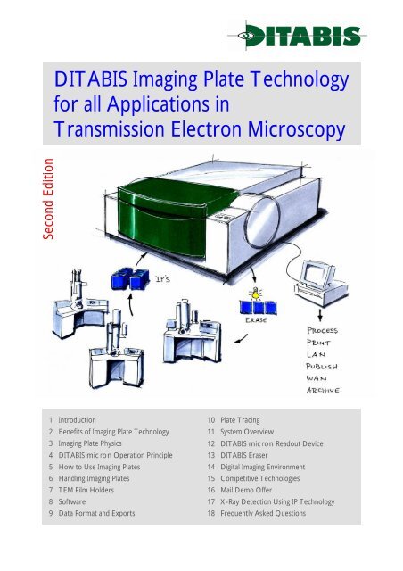
DITABIS Imaging Plate Technology<br />
for all Applications in<br />
Transmission Electron Microscopy<br />
Second Edition<br />
1 Introduction<br />
2 Benefits of Imaging Plate Technology<br />
3 Imaging Plate Physics<br />
4 DITABIS micron Operation Principle<br />
5 How to Use Imaging Plates<br />
6 Handling Imaging Plates<br />
7 TEM Film Holders<br />
8 Software<br />
9 Data Format and Exports<br />
10 Plate Tracing<br />
11 System Overview<br />
12 DITABIS micron Readout Device<br />
13 DITABIS Eraser<br />
14 Digital Imaging Environment<br />
15 Competitive Technologies<br />
16 Mail Demo Offer<br />
17 X-Ray Detection Using IP Technology<br />
18 Frequently Asked Questions
©<br />
Imaging Plate Technology<br />
! ! ! ! ! ! ! ! ! ! ! ! ! ! ! ! ! ! ! ! ! ! ! ! ! ! ! ! ! ! ! ! ! ! ! ! ! ! ! ! ! ! ! ! ! ! ! ! ! ! ! ! ! ! ! ! ! ! ! ! ! ! !<br />
1 Introduction<br />
Classical TEM Imaging using negative film materials has been partly replaced by CCD<br />
technologies in the past 10 years. While film still produces highest definition images on a big<br />
field of view it shows strong limitations in dynamics and linearity. CCD-cameras, which on<br />
one hand have the advantage of producing direct digital images, on the other hand only<br />
cover a limited area at moderate dynamic range. A third alternative, i.e. Digital Imaging Plate<br />
Technology, although known for some time, is now available and affordable for broad use<br />
and overcomes the limitations of both technologies: The results are high definition and<br />
digital images.<br />
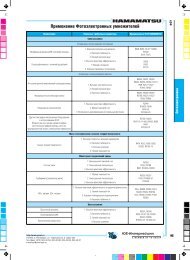
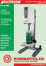
Imaging Plate, Scale: 1:2<br />
Imaging Plates are nearly ideal electron detectors that give you highest quality digital Images.<br />
DITABIS Imaging Plate Technology enhances your results with all the benefits of digital<br />
imaging. Exploring the advantages of the Imaging Plate Technology, best results are obtained<br />
in resolution, linearity, sensitivity, dynamic range and DQE.<br />
2 Benefits of Imaging Plate Technology<br />
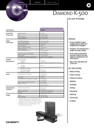
Imaging Plate usable Area<br />
# Highest definition images on a big usable area<br />
The Imaging Plate reader micron reads with a pixel size of 15µm up to 50µm,<br />
(different instrument versions available) and can use the full area of 80x90mm<br />
resulting in images with up to 6000x5000 Pixel. Compared with CCD cameras<br />
that have pixel sizes in the same range, the detected area of the Imaging Plate is<br />
about the tenfold of the CCD. The definition of the images is excellent. This is<br />
shown with the Point Spread Function (PSF), that shows the coupling of<br />
neighboring pixels. With the Imaging Plate, the information is highly localized<br />
within the pixel. This results in a high Modulation Transfer Function (MTF). At<br />
highest transmission frequency (one pixel bright, next dark) the modulation is<br />
still as high as 38% (25µm reader device).<br />
CCD usable Area<br />
2048 x 2048<br />
(14µm)<br />
1024 x 1024<br />
(19µm)<br />
6000 Pixel (5000, 3600)<br />
Sensitivity Characteristic<br />
5000 Pixel (4500, 3200)<br />
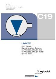
# High dynamic range<br />
The response of the Imaging Plate is linear to the applied electron dose in a<br />
broad dynamic range. The Imaging Plate reader micron digitizes the image data<br />
with 16 bit or 20 bit allowing a contrast of over 6*10 4 or 10 6 . Negative-film in<br />
comparison has only 1*10 2 linear range. Thus more information can be extracted<br />
from one exposure, there is no need for multiple exposures.<br />
Diffraction patterns of a widely varying range of intensities can be observed in a<br />
single exposure and displayed in one image.<br />
Signal Intensity<br />
Imaging Plate<br />
Conventional EM-Film<br />
(non-linear)<br />
Electron Dose (e/µm 2 ) on Detector<br />
Optical Density<br />
# Unrivalled sensitivity<br />
Imaging Plates do not need a minimum dose like negative-film, nor is there a<br />
significant readout noise like with CCDs. This makes the Imaging Plate the ideal<br />
detector for low dose imaging applications. Observing most beam sensitive<br />
specimens the electron dose can be far reduced, compared with negative-film<br />
(IP is about ten times more sensitive than negative-film). At even lower doses<br />
usable images can be obtained, only the quantum noise increases. So you expand<br />
the usable dose range for sensitive samples.<br />
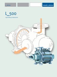
Modulation Transfer Function (25µm)<br />
# High DQE<br />
The inherent amplification of the Imaging Plate and a newly designed detector<br />
system guarantees a high Detection Quantum Efficiency (DQE) for electrons,<br />
even at lowest signals. This means, that a high percentage of the electrons that<br />
hit the plate are detected, resulting in high sensitivity and low noise of the<br />
Imaging Plate detection system.<br />
# Variable Pixel size<br />
The latest member of DITABIS’ Imaging Plate reader family, the micron vario<br />
features a selectable pixel size from 15 to 50µm in 8 steps. Besides the enhanced<br />
resolution, this allows to optimize the readout to your application, generating<br />
only as much data as you need and gives you flexibility for all your applications.<br />
There are also fixed pixel size instruments available for 17.5 and 25µm.<br />
DQE<br />
Nyquist frequency<br />
DITABIS micron, deconvoluted Data<br />
DITABIS micron, deconvoluted Data<br />
Gain Normalization<br />
FUJI FDL 5000<br />
ssCCD Camera<br />
Gain Normalization<br />
Electron Dose (e/µm 2 ) on Detector<br />
! ! ! ! ! ! ! ! ! ! ! ! ! ! ! ! ! ! ! ! ! ! ! ! ! ! ! ! ! ! ! ! ! ! ! ! ! ! ! ! ! ! ! ! ! ! ! ! ! ! ! ! ! ! ! ! ! ! ! ! ! ! !<br />
1 .<br />
DITABIS AG
Imaging Plate Technology<br />
! ! ! ! ! ! ! ! ! ! ! ! ! ! ! ! ! ! ! ! ! ! ! ! ! ! ! ! ! ! ! ! ! ! ! ! ! ! ! ! ! ! ! ! ! ! ! ! ! ! ! ! ! ! ! ! ! ! ! ! ! ! !<br />
# True Linearity<br />
The luminescence signal emitted from the plate while reading is directly proportional to the exciting electron dose. Therefore<br />
the data are directly numerically quantifiable. For comparison: The EM negative-film has a sigmoid nonlinear characteristic that<br />
makes quantification difficult. Due to the linear signal intensity of micron, quantifying the electron dose for diffraction patterns<br />
(EELS spectra and HREM images) is far more accurate than with negative-film.<br />
# Digital image data is instantly available<br />
The DITABIS Imaging Technology is digital with no intermediate stages like chemical development. The data are digitized during<br />
the reading process and are available directly after readout. This gives you all advantages of the modern digital world:<br />
Visualization with zooming and contrast setting at the screen, printing on any PC printer, quantification and archiving on various<br />
media.<br />
# Economy<br />
Imaging Plate Technology is an economical way to produce high quality images. As the plate is reusable for up to 1000 times the<br />
cost per shot is very low. No chemicals or other darkroom equipment is needed, reducing waste and labor. The proprietary<br />
Imaging Plate Technology eliminates time needed for film processing and enlargement, freeing more productive time for your<br />
research. The images are instantly digitally available on your computer for evaluation and further processing of the data.<br />
As the reader is not directly linked to the TEM, one micron instrument can serve multiple different TEMs. Regardless of which<br />
TEM you use the Imaging Plate fits to every microscope. In a typical lab with 100 shots per day the prime costs of a DITABIS<br />
reader are paid off in a year.<br />
3 Imaging Plate Physics<br />
The Imaging Plate is a flexible electron<br />
detector, where an active layer of tiny<br />
crystals locally store high energetic radiation.<br />
The storage crystals are made from doted barium fluoro-bromide embedded in some blue colored resin. The electron<br />
irradiation excites the crystals in their luminescence center to a semi-stable state. The image information, formed by this<br />
excitation is stable for many hours and decays within days. By an illumination with red laser light, the crystals are excited again<br />
and stimulated to release the stored information as blue luminescence signal. The amount of blue light released depends on the<br />
first excitation with electrons and is a direct measure of the electron dose. As this is a physical process it is fully reversible<br />
without degradation, so the Imaging Plate can be reused many times. By exposing to white light for a period of 10 to 15 minutes<br />
all excitation is released and the plate is ready<br />
to be exposed again.<br />
The active layer is protected by a thin<br />
polymer layer on top. It is supported by a<br />
polymer layer and a thin metal (antimagnetic)<br />
base that gives its mechanical stability. (see<br />
figure top right)<br />
As the excitation is stored within the crystal<br />
luminescence centers the number of available<br />
storage cells is virtually unlimited. For this<br />
reason the plate is not saturated in a TEM.<br />
Only the readout device limits the dynamic<br />
range. During exposure the electron enters<br />
the plate and deposits its energy by exciting a<br />
large number of crystal centers. The lateral<br />
electron scattering is limited to a few micron<br />
so the information is highly localized. The<br />
blue color of the resin absorbs the red laser<br />
light while perfectly transmitting the blue<br />
luminescence signal so lateral scattering of<br />
the readout light is greatly reduced.<br />
These features make the Imaging Plate an<br />
ideal electron detector:<br />
# High Sensitivity as one electron produces<br />
a number of photons. So virtually<br />
every single electron can be detected.<br />
# High dynamic range as there is no<br />
saturation.<br />
# Sharp Images as the information is highly<br />
localized (low crosstalk)<br />
# Large detection area (80x90 mm).<br />
# Reusable<br />
Electrons<br />
Laser Beam Scanning<br />
Visible Light<br />
Reusable Imaging Plate<br />
Protective Layer<br />
Photo Stimulable<br />
Phosphor Layer<br />
Polyester Support Layer<br />
Metal Support Layer<br />
Cross-section of<br />
unexposed Imaging Plate<br />
Irradiation with Electrons in<br />
TEM. Crystals are excited<br />
A highly focused laser<br />
beam is scanning the<br />
stored TEM information.<br />
The stored information is<br />
released as blue light<br />
Visible light erases the<br />
Imaging Plate<br />
The erased Imaging Plate<br />
is ready to be exposed<br />
again<br />
! ! ! ! ! ! ! ! ! ! ! ! ! ! ! ! ! ! ! ! ! ! ! ! ! ! ! ! ! ! ! ! ! ! ! ! ! ! ! ! ! ! ! ! ! ! ! ! ! ! ! ! ! ! ! ! ! ! ! ! ! ! !<br />
© DITABIS AG 2 .
L a s e r<br />
©<br />
Imaging Plate Technology<br />
! ! ! ! ! ! ! ! ! ! ! ! ! ! ! ! ! ! ! ! ! ! ! ! ! ! ! ! ! ! ! ! ! ! ! ! ! ! ! ! ! ! ! ! ! ! ! ! ! ! ! ! ! ! ! ! ! ! ! ! ! ! !<br />
4 DITABIS micron Operation Principle<br />
The DITABIS micron is an<br />
high-performance Imaging Plate<br />
readout system dedicated for<br />
TEM use. Unlike medical and<br />
biological applications where<br />
Imaging Plates are used too,<br />
TEM imaging requires small<br />
pixels, highest image quality and<br />
a high dynamic range.<br />
The instrument employs a drum<br />
scanner layout. The Imaging<br />
Plates are fixed to the surface of<br />
a spinning drum and read out by<br />
a laser beam that moves alongside<br />
the drum. Up to 5 plates<br />
are scanned simultaneously<br />
along one slot around the drum<br />
surface in a continuos line (see<br />
figure right).<br />
Collecting<br />
Mirror<br />
P M T<br />
MovingDetectionUnit<br />
Imaging<br />
Drum<br />
Plate<br />
MovingStage<br />
The released luminescence signal from the plates is collected with special high aperture mirror optics and detected with a Photo<br />
Multiplier Tube (PMT). The signal is amplified and converted to digital values with an analog to digital converter (ADC). The data<br />
are sent to a hard disk within the reader that collects the complete data of one scan. After that the image data are transmitted to<br />
the computer system and displayed on the monitor (see figure below).<br />
The collected luminescence<br />
signals are converted to digital<br />
signals of 16 bits. This allows for<br />
65000 shades of grey which is<br />
quite enough for normal TEM<br />
images. Optionally a second data<br />
channel can be used to expand<br />
the dynamic range to 1 million<br />
shades of grey.<br />
A/D<br />
Converter<br />
A/D<br />
Converter<br />
Amplifier<br />
x32<br />
MUX<br />
Amplifier<br />
Amplifier<br />
PMT<br />
Sensor<br />
Imaging Plate Scanner<br />
Laser<br />
390nm<br />
635nm<br />
Luminescence<br />
Imaging Plate<br />
Scanner<br />
SCSI-Disk<br />
Host<br />
Computer<br />
SCSI<br />
Hostadapter<br />
Archiving<br />
System<br />
Image<br />
Display<br />
CPU<br />
System<br />
Disk<br />
Network<br />
The instrument is built to meet the demanding needs of TEM imaging:<br />
# The readout laser is highly focused to a spot diameter of about 5µm. The pixel-to-pixel distanceis 15µm to 50µm (see<br />
variable pixel size). Thus the high focus reduces the cross-talk between neighboring pixels to get maximum sharpness and a<br />
good MTF (Modulation Transfer Function, up to 38% at Nyquist for 25.0µm pixel).<br />
# The collecting mirror has a high aperture so it is collecting a great portion of the light emitted. In combination with the<br />
sensitive Photo Multiplier detector an enormous sensitivity and DQE (Detection Quantum Efficiency, about 80%) is<br />
reached.<br />
# The instrument has two synchronous data channels of 16 bit each. When operating in the High Dynamic mode the second<br />
channel converts an amplified version of the PMT signal. So two images are obtained one with high and one with lower gain<br />
(factor set to 32). The two images can be numerically combined to form an image with at least 20 bit data dynamic range<br />
(1:1 million).<br />
! ! ! ! ! ! ! ! ! ! ! ! ! ! ! ! ! ! ! ! ! ! ! ! ! ! ! ! ! ! ! ! ! ! ! ! ! ! ! ! ! ! ! ! ! ! ! ! ! ! ! ! ! ! ! ! ! ! ! ! ! ! !<br />
3 .<br />
DITABIS AG
Imaging Plate Technology<br />
! ! ! ! ! ! ! ! ! ! ! ! ! ! ! ! ! ! ! ! ! ! ! ! ! ! ! ! ! ! ! ! ! ! ! ! ! ! ! ! ! ! ! ! ! ! ! ! ! ! ! ! ! ! ! ! ! ! ! ! ! ! !<br />
5 How to Use Imaging Plates<br />
Imaging Plates are used in TEM like negative film material. The plate is inserted into the TEM film holder and loaded to the TEM<br />
film camera. Unlike sheet film the unexposed Imaging Plate is not sensitive to light so it can be handled at ambient light. Imaging<br />
Plates are not hygroscopic so there is no need for desiccation.<br />
Exposing in the TEM is straightforward. You can use the emulsion setting you are using for your films. But unlike film the Imaging<br />
Plate can also be exposed with much lower or much higher dose. When performing Low Dose applications the electron dose<br />
can be lowered to one tenth of the dose needed on film thus preserving beam sensitive specimens. For stable samples the dose<br />
can be increased to lower the electron noise.<br />
When recording diffraction patterns the dose typically cannot be determined exactly but has to be estimated. Due to the high<br />
dynamics of the Imaging Plate it is very forgiving and nearly always will create perfect images on first trial.<br />
After exposure, the Imaging Plate is unloaded from the TEM and transferred to the micron reader. This step has to be done in<br />
the dark because the exposed plate is light sensitive now. Unlike negative film, the plate is not very sensitive to light so a bright<br />
yellow save-light can be used.<br />
For reading the Imaging Plates have to be fixed flatly onto the surface of the drum. This is done by a plate loading mechanism.<br />
Up to 20 plates can be loaded to the drum and scanned in one batch.<br />
To load the imaging plates to the reader the plates are taken out of the TEM film holder and fed to the reader loading slots, four<br />
at a time. The automatic loading mechanism drags the plates into the instrument and clamps them to the drum. This is repeated<br />
until all twenty plates are loaded. It is possible to load any number of plates from 1 to 20.<br />
Next the plates are scanned. The read-out process can be parameterized to optimize for special applications. Reading time<br />
depends on the number of plates loaded and is about 45 minutes for 20 plates (25.0µm instrument).<br />
After reading the plates are unloaded again. This step can be done at ambient light. Before using the plates again they have to be<br />
erased. Erasing is performed on a light box that illuminates the plate with bright white light. The plates are put on top of the<br />
DITABIS eraser for about 15 minutes. Then the plates can be put back to the TEM film holders and camera for new exposure.<br />
6 Handling Imaging Plates<br />
The Imaging Plate has a very thin protective layer as the electrons must be able to penetrate it. Therefore the plate surface is<br />
vulnerable to damage. Only touch the plate at the edges, avoid to touch the surface even with gloves. Scratches on the surface<br />
will be visible in the images.<br />
The lifetime of the plates is mainly limited by the mechanical degradation of the surface. By treating carefully plates can be reused<br />
1000 times.<br />
The plates are flexible and relatively stable. Do not bend the plates strongly, however gentle bending to insert the plate in the<br />
film holder is allowed.<br />
7 TEM Film Holders<br />
The Imaging Plate comes in a format of 81x100mm (3,25"x4"; standard film dimensions). The reader is fixed to that format so no<br />
other plate format can be used. There are holders available for this format from all TEM manufacturers that fit to virtually every<br />
instrument type. For some rare older TEMs, DITABIS engineered own Imaging Plate holders.<br />
Depending on the film holders you are using there are three variants of Imaging Plates available that fit your holders.<br />
! ! ! ! ! ! ! ! ! ! ! ! ! ! ! ! ! ! ! ! ! ! ! ! ! ! ! ! ! ! ! ! ! ! ! ! ! ! ! ! ! ! ! ! ! ! ! ! ! ! ! ! ! ! ! ! ! ! ! ! ! ! !<br />
© DITABIS AG 4 .
©<br />
Imaging Plate Technology<br />
! ! ! ! ! ! ! ! ! ! ! ! ! ! ! ! ! ! ! ! ! ! ! ! ! ! ! ! ! ! ! ! ! ! ! ! ! ! ! ! ! ! ! ! ! ! ! ! ! ! ! ! ! ! ! ! ! ! ! ! ! ! !<br />
8 Software<br />
The DITABIS micron Imaging<br />
Plate Reader is controlled by a<br />
PC. It comes with a software<br />
package for device control and<br />
image viewing and analysis.<br />
The software runs on Windows<br />
95/98/NT/2000/XP platforms.<br />
The reader is directly linked to<br />
the computer which controls all<br />
functions. After readout the<br />
image files are available on the<br />
computer or network drive.<br />
Reader control functions<br />
# Loading and unloading plates<br />
# Scan parameters in pre-defined and user definable parameter sets<br />
# Full control of all scanning parameters: gain, pixel size, data channels<br />
# User defined scanning area to restrict readout on the actual exposed area (reduce amount of data)<br />
# Unique filename and comment for every image, based on common filename and comment input<br />
# Import of microscope log files or text file to the header of each image<br />
Viewing and handling images<br />
# Preview of images allows quick handling of large images<br />
# Comment and scanning parameters in header of image file for file identification<br />
# Database function for quick search of images<br />
# Look-Up Table to adjust contrast and brightness to view details in image<br />
# Zoom functions<br />
# Saving in proprietary format and export to standard and DTP formats<br />
# Printing on PC printer<br />
Image Processing<br />
# Various filter functions, custom convolution filters<br />
# Rotation of images<br />
# Image Arithmetic between several images<br />
# All functions can be restricted to a Region Of Interest<br />
# Merge Files with different gain to high dynamic data set<br />
# Change pixel size (binning) and average macro pixels<br />
# Undo function for all image processing functions<br />
Analyze functions<br />
# Point measurements: intensity, distance and location<br />
# Line measurements: line profile with lateral average, data export<br />
# Area measurements: intensity, deviation, geometric data<br />
# 2-dimensional FFT<br />
# 3D-Plot of intensities<br />
# Peak find function: Magnitude / Angle / Position / Shape<br />
Interactive Help system<br />
! ! ! ! ! ! ! ! ! ! ! ! ! ! ! ! ! ! ! ! ! ! ! ! ! ! ! ! ! ! ! ! ! ! ! ! ! ! ! ! ! ! ! ! ! ! ! ! ! ! ! ! ! ! ! ! ! ! ! ! ! ! !<br />
5 .<br />
DITABIS AG
Imaging Plate Technology<br />
! ! ! ! ! ! ! ! ! ! ! ! ! ! ! ! ! ! ! ! ! ! ! ! ! ! ! ! ! ! ! ! ! ! ! ! ! ! ! ! ! ! ! ! ! ! ! ! ! ! ! ! ! ! ! ! ! ! ! ! ! ! !<br />
9 Data Format and Exports<br />
The DITABIS software has a multitude of image analysis functions as described above. The functions provided are common<br />
image analysis functions that are general purpose and not dedicated to special TEM applications. The philosophy is to use the<br />
micron software to extract the data numerically (positions, magnitude, profiles, areas etc.), to export these data to a text file<br />
and finally to do the application specific processing by a spreadsheet program or proprietary software. In cases where this is not<br />
feasible, our image data format can be directly accessed by other special software either third party or self-written.<br />
The DITABIS micron software uses a proprietary image data format. The format is capable of handling 16, 24 and 32 bit<br />
greyscale per pixel. DITABIS has chosen a proprietary format as there are no standard formats beyond 16 bit. The data format is<br />
open so there is a detailed description of the format available. This allows to import the files to several third party software<br />
packages (for example the analySIS software package from Soft Imaging System reads our format) as well as to access the files by<br />
special self-written software.<br />
micron images are easily converted to 16 bit TIFF that can be read by most common image software packages. The DITABIS<br />
software also allows export to several 8 bit formats for publishing and printing. The High Dynamic images with 24 or 32 bit<br />
however cannot be converted without losses to standard formats as these formats are limited to 16 bit. Converting to 16 bit will<br />
reduce the dynamic range, which in most cases can be compensated by applying look-up-table functions.<br />
Plug-In for Adobe® PhotoShop<br />
In order to allow professional publishing of your TEM images obtained with micron we now provide a Plug-In for Adobe®<br />
PhotoShop. With this plug-in the micron images can be opened directly as a 16 bit grey image. This allows to handle the<br />
micron images on every computer PhotoShop is installed on. When opening these in PhotoShop the 24 and 32 bit micron<br />
images are converted to 16 bit. The information from the file header is copied to the PhotoShop file info fields. From Photoshop<br />
the images can be saved as TIFF (8 or 16 bit) or JPEG (after conversion to 8 bit). The header information will be transfered to<br />
these formats.<br />
PhotoShop as a sophisticated and user friendly software offers a wide variety of functions for processing and publishing images<br />
that exceed the functionality of the micron software.<br />
# Various interactive contrast setting (Level, Auto-Level, Curves)<br />
# Printing with interactive setting of print size<br />
# Printout of image along with filename and comments.<br />
# Annotation of the image with overlay of text and graphics with optional color.<br />
# Printout of image galleries<br />
The Plug-In operates with PhotoShop PC versions 5 to 7 and with the Mac versions 4 to 7.<br />
It can be downloaded free of charge from www.ditabis.de.<br />
! ! ! ! ! ! ! ! ! ! ! ! ! ! ! ! ! ! ! ! ! ! ! ! ! ! ! ! ! ! ! ! ! ! ! ! ! ! ! ! ! ! ! ! ! ! ! ! ! ! ! ! ! ! ! ! ! ! ! ! ! ! !<br />
© DITABIS AG 6 .
©<br />
Imaging Plate Technology<br />
! ! ! ! ! ! ! ! ! ! ! ! ! ! ! ! ! ! ! ! ! ! ! ! ! ! ! ! ! ! ! ! ! ! ! ! ! ! ! ! ! ! ! ! ! ! ! ! ! ! ! ! ! ! ! ! ! ! ! ! ! ! !<br />
10 Plate Tracing<br />
Due to the physical circumstances that the TEM exposure number can not be imprinted to the imaging plate directly, both<br />
exposure number and TEM settings have to be transferred on an independent way to the corresponding image file.<br />
‘Plate Tracing’ is a software-controlled method providing you with almost the same security as you are used from classic<br />
negative film or from CCD cameras – thus preventing any mismatch of TEM settings with the corresponding exposures.<br />
Imaging plates are marked with a unique small barcode label permanently fixed on the edge of the imaging plate’s active layer,<br />
just inside the usable area. This barcode is used to trace - under software control - the respective imaging plate through the<br />
complete imaging process, from loading to the TEM until reading it in the micron. Depending on your TEM there are different<br />
ways how the plates are traced during the process. For further information please contact us.<br />
11 System Overview<br />
The DITABIS micron System comprises the Imaging Plates, the device with the controlling computer and the DITABIS eraser.<br />
The PC runs the DITABIS operating software. For computer requirements please see chapter 12. Technical Information on the<br />
DITABIS eraser can be found in chapter 13.<br />
As you can see in the figure above, the system does not require a great deal of space in a room that can be darkened.<br />
! ! ! ! ! ! ! ! ! ! ! ! ! ! ! ! ! ! ! ! ! ! ! ! ! ! ! ! ! ! ! ! ! ! ! ! ! ! ! ! ! ! ! ! ! ! ! ! ! ! ! ! ! ! ! ! ! ! ! ! ! ! !<br />
7 .<br />
DITABIS AG
Imaging Plate Technology<br />
! ! ! ! ! ! ! ! ! ! ! ! ! ! ! ! ! ! ! ! ! ! ! ! ! ! ! ! ! ! ! ! ! ! ! ! ! ! ! ! ! ! ! ! ! ! ! ! ! ! ! ! ! ! ! ! ! ! ! ! ! ! !<br />
12 DITABIS micron Readout Device<br />
The Imaging Plate reader micron is a compact desktop device. The instrument comes with connection equipment to the<br />
computer (SCSI-adapter and cables). There are three instrument versions available: micron vario with selectable resolution<br />
from 15µm to 50µm, and two fixed-resolution devices with 25.0µm pixel size (micron 25µm) for general purpose applications<br />
and 17.5µm for higher resolution applications (micron 17.5µm).<br />
Specifications<br />
Data format<br />
Imaging Plate size<br />
Effective area<br />
Plates to read<br />
A/D-conversion<br />
Dynamic range<br />
Pixel sizes<br />
(depending on instrument)<br />
Number of pixels<br />
(X by Y)<br />
16 / 24 / 32 bit data format with comment and setting information in header<br />
81x100 mm<br />
80 x 90 mm<br />
1 to 20 plates per run<br />
2 channels of 16 bit at different gains, 20 bit combined<br />
6 orders of magnitude at one scan, higher for multiple scans<br />
15µm<br />
(1)<br />
6000<br />
5333<br />
17.5µm<br />
(1; 2)<br />
5142<br />
4571<br />
20µm<br />
(1)<br />
4500<br />
4000<br />
File size per image 64MB 47MB 36MB 20MB 16MB 12MB 9MB 6MB<br />
Readout time (per plate) 3min 2:70min 2:20min 2min 1:50min 1:30min 1:20min 1min<br />
Power requirements<br />
Dimensions<br />
Weight<br />
230V-50Hz; 120V-60Hz, 100W<br />
675 x 580 x 305 mm (W/D/H)<br />
60 kg<br />
25µm<br />
(1; 3)<br />
3600<br />
3200<br />
30µm<br />
(1)<br />
3000<br />
2666<br />
35µm<br />
(1)<br />
2571<br />
2285<br />
40µm<br />
(1)<br />
2250<br />
2000<br />
(1) … ‘micron vario’ (2) … ‘micron 17.5µm’ (3) … ‘micron 25µm’<br />
50µm<br />
(1)<br />
1800<br />
1600<br />
Computer<br />
All functions of the Imaging Plate reader micron are controlled by a computer running on Windows 98/NT/2000/XP and the<br />
DITABIS micron software. The computer usually is not included in the package but supplied locally (on request we also can<br />
supply a computer). Depending on the local computer environment the computer also may serve as the image server, archiving<br />
station and print server. It is not recommended to use the computer for multiple devices (third party devices).<br />
For the computer any state of the art Windows PC will do. For interfacing with the instrument a free PCI slot for the SCSIinterface<br />
card (included) and one COM port is required. For storing and archiving images a big hard disk and a CD or DVD<br />
writer is recommended.<br />
! ! ! ! ! ! ! ! ! ! ! ! ! ! ! ! ! ! ! ! ! ! ! ! ! ! ! ! ! ! ! ! ! ! ! ! ! ! ! ! ! ! ! ! ! ! ! ! ! ! ! ! ! ! ! ! ! ! ! ! ! ! !<br />
© DITABIS AG 8 .
©<br />
Imaging Plate Technology<br />
! ! ! ! ! ! ! ! ! ! ! ! ! ! ! ! ! ! ! ! ! ! ! ! ! ! ! ! ! ! ! ! ! ! ! ! ! ! ! ! ! ! ! ! ! ! ! ! ! ! ! ! ! ! ! ! ! ! ! ! ! ! !<br />
13 DITABIS Eraser<br />
The DITABIS eraser was designed to<br />
erase the latent image information in<br />
the Imaging Plate that remains after<br />
reading. The plates are put face down<br />
on the trackage system that is designed<br />
to protect the plate surface.<br />
The DITABIS eraser completes the<br />
system and ensures that the Imaging<br />
Plates are erased within 15 min and can<br />
be reused without damages.<br />
If desk space is rare the eraser can be<br />
placed on top of the micron reader<br />
device.<br />
Specifications<br />
Surface<br />
Phosphor surface<br />
Illumination<br />
Overall size<br />
Erasing time<br />
Acrylic glass pane with mounted trackage system<br />
ca. 590 x 350 mm (max. 20 Imaging Plates)<br />
2 x 18 Watt, 5400 Kelvin (neon tubes)<br />
ca. 650 x 430 x 90 mm<br />
10-15 min.<br />
14 Digital Imaging Environment<br />
If the computer is not in a network but operating as a stand alone system, the image files have to be stored on its local disk. As<br />
the hard disk will be filled soon you will need an archiving device. Most convenient is a CD Writer that also allows you to carry<br />
the data to any desktop computer for evaluation. It is also possible to use a tape streamer or a DVD writer. It is recommended<br />
to use an image database to keep track of the images.<br />
If the computer is part of a network the data usually are placed directly on a network server. Also archiving and printing may be<br />
performed by the network servers. All desktop computers connected to the network have instant access to the image data as<br />
soon as the readout is completed.<br />
Printing<br />
When working with digital images image and data analysis will be done directly on the PC as the interactive representation of<br />
the images at the screen shows quite more information than a printout. But finally for documentation, posters or other<br />
publications processed images will be required to be printed out.<br />
There are a multitude of printers available and you can use every printer that comes with a windows driver. Quality and cost of<br />
the printers varies widely and the choice of a printer is a matter of money and personal needs and taste.<br />
For daily work we recommend to use a good laser printer (1200dpi) that is inexpensive and produces relatively good images.<br />
For scientific presentations we recommend a dye sublimation printer (expensive but highest quality) or an ink jet printer on<br />
photo paper (good quality).<br />
Printer types<br />
Printer type Printer cost Costs per print Quality<br />
Laser Printer 1200dpi Moderate Very low Moderate, limited contrasts<br />
Color Laser Printer High Low Moderate, higher contrast<br />
Ink Jet Printer on photo paper Low Moderate Photo realistic<br />
Dye sublimation Printer High High Photo realistic (best)<br />
! ! ! ! ! ! ! ! ! ! ! ! ! ! ! ! ! ! ! ! ! ! ! ! ! ! ! ! ! ! ! ! ! ! ! ! ! ! ! ! ! ! ! ! ! ! ! ! ! ! ! ! ! ! ! ! ! ! ! ! ! ! !<br />
9 .<br />
DITABIS AG
Imaging Plate Technology<br />
! ! ! ! ! ! ! ! ! ! ! ! ! ! ! ! ! ! ! ! ! ! ! ! ! ! ! ! ! ! ! ! ! ! ! ! ! ! ! ! ! ! ! ! ! ! ! ! ! ! ! ! ! ! ! ! ! ! ! ! ! ! !<br />
15 Competitive Technologies<br />
The Imaging Plate technology overcomes limitations of both EM negative film material and slow scan CCD-camera technology.<br />
The following table compares the characteristics of the Imaging Plate to film and CCD.<br />
Imaging Plate versus Negative Film<br />
Imaging Plate<br />
Usable Area 80 x 90 mm 80 x 95mm<br />
Number of Pixels Up to 6000 x 5000<br />
Pixel size<br />
15µm to 50 µm variable<br />
Negative Film Material<br />
The silver crystals of film are smaller than the IP<br />
pixel, but only give a digital information (black or<br />
white). Several crystals are needed for a gray pixel.<br />
Therefore the resulting resolution is comparable.<br />
Sensitivity Over 10 times more sensitive than film Standard negative film material needs a minimum<br />
dose to darken the crystals and at higher doses the<br />
negative-film gets saturated (sigmoid characteritics)<br />
Dynamic range 6 Orders of magnitude and more, linear 10² linear and up to 10³ non-linear<br />
Quantification Direct quantification Complicated: needs scanning and calibration<br />
Handling<br />
Economy<br />
Loading to TEM at day light<br />
No chemical development needed<br />
Investment comparable to darkroom<br />
equipment and optical scanner.<br />
Low running cost per shot<br />
Device concept Off-line Off-line<br />
Handling only in the dark. Needs wet chemical<br />
process for development and creates chemical<br />
waste<br />
Moderate costs for film material and development,<br />
but heavily summarizing over years<br />
Imaging Plate versus slow scan CCD-camera<br />
Imaging Plate<br />
Usable Area 80 x 90 mm About 24 x 24mm<br />
slow scan CCD-camera<br />
Number of Pixels Up to 6000 x 5000, variable 4096 x 4096 (extremely expensive)<br />
2048 x 2048<br />
1024 x 1024<br />
Pricing Price range between 1k and 2k CCD Price depends very much on the size<br />
Pixel size 15µm to 50µm variable 15µm to 25µm, fixed<br />
Sharpness Best sharpness and MTF Cross-talk in scintillator limits MTF<br />
Detection Quantum<br />
Efficiency (DQE)<br />
High DQE (~90%)<br />
DQE and MTF are linked. Systems with good MTF<br />
have poor DQE and vice versa<br />
Sensitivity Comparable but lower noise at low dose High noise at low doses because of constant<br />
readout noise<br />
Dynamic range: 6 Orders of magnitude and more, linear 4 Orders of magnitude<br />
Quantification: Direct quantification Direct quantification<br />
Handling Easy Simple<br />
Economy<br />
Investment comparable<br />
IP reader can serve multiple TEMs<br />
Device concept Off-line On-line<br />
Fixed to one TEM<br />
! ! ! ! ! ! ! ! ! ! ! ! ! ! ! ! ! ! ! ! ! ! ! ! ! ! ! ! ! ! ! ! ! ! ! ! ! ! ! ! ! ! ! ! ! ! ! ! ! ! ! ! ! ! ! ! ! ! ! ! ! ! !<br />
© DITABIS AG 10 .
©<br />
Imaging Plate Technology<br />
! ! ! ! ! ! ! ! ! ! ! ! ! ! ! ! ! ! ! ! ! ! ! ! ! ! ! ! ! ! ! ! ! ! ! ! ! ! ! ! ! ! ! ! ! ! ! ! ! ! ! ! ! ! ! ! ! ! ! ! ! ! !<br />
16 Mail Demo Offer<br />
The preceeding chapters describe the unrivalled advantages of DITABIS Imaging Plate technology. If you are interested in this<br />
promising technology you may want to have a test with your TEM and your specimen – as this is the best way to compare<br />
results.<br />
We offer you a so-called Mail Demo: We send you some Imaging Plates. You do the exposures at your TEM and send the<br />
exposed plates back to us by express mail. We read out the plates on micron in our lab and send you the obtained image data<br />
on a CD.<br />
# Interested? Then contact us for the details at ‘contact@ditabis.de’.<br />
A Demo CD is available on request that contains a demonstration version of the software along with all documentation and a<br />
library of images. This allows you to evaluate the software and obtain a live impression of how the images look on your<br />
computer or printout. Please call us or send an e-mail to contact@ditabis.de.<br />
17 X-Ray Detection Using Imaging Plate Technology<br />
Imaging Plates are sensitive to electrons, but also for α-, β-, and γ- as well as for X-rays. DITABIS’ imaging plate reader micron<br />
is designed for electron detection in the TEM but can be used for detection of these radiations, too. Most interesting probably is<br />
the possibility to use the system for X-ray diffraction analysis.<br />
If you intend to use the system for non-TEM imaging applications, please take the following into consideration:<br />
• The format of our imaging plates is 80x100mm with a usable area of 80x90mm which cannot be changed.<br />
• The Imaging Plates used are optimised for high spatial resolution needed for TEM imaging. The plates therefore have a<br />
quite thin active layer. Compared with the imaging plates generally used for X-ray these plates are somewhat less<br />
sensitive. As DITABIS’ micron is a very sensitive reading device this usually is no problem. The plates are still much<br />
more sensitive than X-ray films.<br />
• Normally other plate types can be used after proper modification for our instrument (punching). This increases the<br />
sensitivity by a factor of two but at the same time reduces the resolution to some extent.<br />
18 Frequently Asked Questions<br />
Q: Can Imaging Plates be used also at higher accelerating voltages?<br />
A: Imaging Plates can be used in the range from 50 to 400kV. With accelerating Voltages above 300kV the efficiency goes down<br />
to some degree but is still useful.<br />
Q: You state a re-use of Imaging Plates of 1000 times. Do the plates degenerate at the end of the lifetime?<br />
A: The degeneration of the plate is mainly mechanical. This comprises possible degeneration of the plate surface (scratches)<br />
that might become visible in the image and mechanical wear out (bending of edges). The lifetime of the plate is mainly<br />
influenced by the care when handling it. The response of the plate (sensitivity, dynamic) is hardly degenerating. Finally, with<br />
routine use in the TEM the Imaging Plate could not be destroyed by electron dose.<br />
Q: The plate is erased by reading. Is it possible to read it a second time?<br />
A: Scanning reads out stored information of the plate but not completely. When the plate is read a second time about half of<br />
the signal intensity is read but the image looks the same. Multiple scans are useful to expand the dynamic range or to adapt<br />
the reader settings.<br />
Q: How long may the plates be stored between exposure and readout?<br />
A: Usually it is best to read the plates within two days. Especially Low Dose exposures shall be read within this period. High<br />
dose applications and diffraction patterns can be stored for up to one week without adverse effects.<br />
Q: Do the plates need to be desiccated before loading to the TEM?<br />
A: Imaging Plates are not hygroscopic and do not need to be desiccated. If desiccated however pumping time goes a little bit<br />
down.<br />
! ! ! ! ! ! ! ! ! ! ! ! ! ! ! ! ! ! ! ! ! ! ! ! ! ! ! ! ! ! ! ! ! ! ! ! ! ! ! ! ! ! ! ! ! ! ! ! ! ! ! ! ! ! ! ! ! ! ! ! ! ! !<br />
11 .<br />
DITABIS AG
Imaging Plate Technology<br />
! ! ! ! ! ! ! ! ! ! ! ! ! ! ! ! ! ! ! ! ! ! ! ! ! ! ! ! ! ! ! ! ! ! ! ! ! ! ! ! ! ! ! ! ! ! ! ! ! ! ! ! ! ! ! ! ! ! ! ! ! ! !<br />
Q: How big are the image data files?<br />
A: This depends on the mode of reading and the pixel size. For 25µm standard images are about 20MB per image. High<br />
Dynamic Images are 30 or 40MB per image, depending on the mode of storage. For other resolutions (15/17.5/35/50µm)<br />
files sizes for standard images are 60/40/12/6MB.<br />
Q: Is the micron software also available for MAC computers or LINUX?<br />
A: No, MAC or LINUX versions are not available. But micron images can easily be imported by MAC programs for further<br />
image processing. For DITABIS’ PhotoShop-Plug In see chapter 9.<br />
Q: Is it possible to run copies of the software on other computers?<br />
A: The software is licence protected with a hardware key. Additional licences may be bought to run on other installations. If<br />
the software is run without the licence key it is running in a demonstration mode. In this mode the software may be used<br />
for viewing and printing. Most functions are available except data export.<br />
Q: Is the micron-mark and exposure number of the microscope recorded on the plate?<br />
A: As the Imaging Plate is only sensitive to high energy radiation unfortunately this information is not recorded. But there is a<br />
way to connect this information to the image file, which then is stored in the images header (see chapter 10 above). If the<br />
magnification is recorded or known it is possible to place a micron mark as an image overlay within the micron software.<br />
Q: Are there parts in the device that need service or are wearing out?<br />
A: There are no parts that require regular service or have a limited lifetime in the instrument. Service only is required in case of<br />
possible instrument faults.<br />
Q: How many plates can be loaded to my TEM?<br />
A: This depends on the microscope. Generally as many plates fit into the magazine as film sheets.<br />
Q: What is your software upgrade policy?<br />
A: Generally software upgrades are free and can be downloaded from our web site.<br />
Q: What are the differences between the DITABIS micron and the Fuji FDL 5000?<br />
A: Both instruments use the same technology and have a similar performance at 25µm. The DITABIS instrument has a variable<br />
resolution down to 15µm, is considerably cheaper and uses a much smaller footprint (desktop instrument). The main<br />
difference besides this is the layout of the detector. The DITABIS micron is recording the data linear with a dynamic<br />
resolution of 20bit. The FDL 5000 has a logarithmic response with only 14 bit ADC. The DITABIS micron is directly<br />
controlled by the computer while the FDL is an off-line device.<br />
Q: Is it possible to clean the plate surface?<br />
A: In case it is necessary you may clean the plate with pressurized air or a soft tissue. If this is not enough even some alcohol<br />
may be used. Be careful not to scratch the surface, even microscopic scratches may become visible in the image.<br />
Q: What reader resolution type do you recommend for what application?<br />
A: The micron vario is preferable if you have different applications and want the flexibility to optimize your readout. For the<br />
lower budget the 25.0µm standard device is recommended.<br />
For the readout of diffraction patterns generally a lower resolution is sufficient. TEM images to view and printout are best<br />
scanned in a medium range (17.5 to 25µm). For high resolution applications and 3D reconstruction the highest resolution is<br />
required.<br />
The main difference is the pixel size (resolution), but this has some impact on data output and read-out time. (See<br />
specifications table in chapter 12 above)<br />
# Do you have further questions? Do not hesitate to contact us at contact@ditabis.de.<br />
! ! ! ! ! ! ! ! ! ! ! ! ! ! ! ! ! ! ! ! ! ! ! ! ! ! ! ! ! ! ! ! ! ! ! ! ! ! ! ! ! ! ! ! ! ! ! ! ! ! ! ! ! ! ! ! ! ! ! ! ! ! !<br />
© DITABIS AG 12 .
DITABIS AG<br />
Imaging Plate Technology for all Applications in Transmission Electron Microscopy<br />
! ! ! ! ! ! ! ! ! ! ! ! ! ! ! ! ! ! ! ! ! ! ! ! ! ! ! ! ! ! ! ! ! ! ! ! ! ! ! ! ! ! ! ! ! ! ! ! ! ! ! ! ! ! ! ! ! ! ! ! ! ! !<br />
Sales Representative<br />
Digital Biomedical Imaging Systems AG<br />
Stuttgarter Strasse 13<br />
D-75179 Pforzheim (Germany)<br />
Fon: +49(0)7231 589790<br />
Fax: +49(0) 7231 589791<br />
E-Mail: contact@ditabis.de<br />
Internet: www.ditabis.de<br />
! ! ! ! ! ! ! ! ! ! ! ! ! ! ! ! ! ! ! ! ! ! ! ! ! ! ! ! ! ! ! ! ! ! ! ! ! ! ! ! ! ! ! ! ! ! ! ! ! ! ! ! ! ! ! ! ! ! ! ! ! ! !<br />
© DITABIS AG