
You also want an ePaper? Increase the reach of your titles
YUMPU automatically turns print PDFs into web optimized ePapers that Google loves.
GTi SERIES<br />
W10GTi MkII<br />
W12GTi MkII<br />
W15GTi MkII<br />
automotive<br />
subwoofer<br />
owner’s manual<br />
THANK YOU<br />
for choosing a <strong>JBL</strong> ® GTi Series subwoofer.<br />
GTi subwoofers are designed to<br />
provide maximum sound output in a<br />
variety of enclosure types while<br />
maintaining the superb sound quality<br />
associated with <strong>JBL</strong>. To ensure the best<br />
subwoofer performance, we strongly<br />
re<strong>com</strong>mend that installation be entrusted to a<br />
qualified professional. Although these instructions<br />
explain how to install a GTi Series subwoofer in<br />
a general sense, they don’t show the specific<br />
installation procedures that may be required for<br />
your particular vehicle. If you feel you don’t have<br />
the necessary tools or experience, don’t attempt<br />
the installation yourself; rather, ask your authorized<br />
<strong>JBL</strong> dealer about professional-installation options.
INSTALLATION WARNINGS AND TIPS<br />
WARNING<br />
Playing loud music in an automobile can<br />
hinder your ability to hear traffic, as well<br />
as permanently damage your hearing.<br />
We re<strong>com</strong>mend listening at low levels<br />
while driving. <strong>JBL</strong> accepts no liability for<br />
hearing loss, bodily injury or property<br />
damage resulting from use or misuse of<br />
this product.<br />
YOUR CAR AND BASS<br />
REPRODUCTION<br />
Depending on the size of the vehicle’s<br />
interior listening space, reproduced<br />
frequencies below 80Hz may be boosted<br />
by nearly 12dB per octave as frequency<br />
decreases. This effect, <strong>com</strong>monly known<br />
as transfer function, or cabin gain, plays<br />
an important role in defining the in-car<br />
frequency response of your subwoofer.<br />
It is displayed graphically, along with<br />
freespace response, on the enclosed<br />
data sheet for your GTi subwoofer.<br />
POWER-HANDLING<br />
LIMITATIONS<br />
The power-handling capacity of any<br />
subwoofer is related to the excursion<br />
limit of its suspension and its ability to<br />
dissipate heat. A speaker reaches its<br />
excursion-limited power-handling<br />
capacity when its suspension is<br />
stretched to its limit. The excursion<br />
curve shown on the Enclosure Design<br />
Sheet (included with your woofer)<br />
displays cone excursion at the input<br />
power level required to drive the woofer<br />
to maximum linear excursion (X max ).<br />
The input power shown may be used<br />
as instantaneous input only.<br />
Thermal power handling is determined<br />
by the amount of heat that may be<br />
dissipated by the driver’s voice coil.<br />
The power-handling rating assigned<br />
to your GTi Series subwoofer is its<br />
thermal-power-handling rating. This<br />
rating assumes a clean (unclipped)<br />
signal. A clipped waveform has much<br />
higher average power, due to the longer<br />
duty cycle at the top and bottom of the<br />
waveform; it will heat the woofer’s voice<br />
coil faster than a clean signal and may<br />
damage the voice coil. A square wave<br />
has a 100% duty cycle and is extremely<br />
dangerous for any speaker. Audible<br />
distortion in the output of your woofer<br />
is an indication that your amplifier may<br />
be clipping, which could damage your<br />
speakers over time.<br />
2
CHOOSING AN ENCLOSURE<br />
GTi Series subwoofers are optimized to<br />
perform best in small sealed, vented and<br />
bandpass enclosures. While infinitebaffle<br />
mounting of GTi Series subs is<br />
possible, power handling will be<br />
<strong>com</strong>promised since there will be no<br />
enclosed volume of air to help the<br />
speaker’s suspension control the motion<br />
of the woofer’s cone. For this reason,<br />
we do not re<strong>com</strong>mend infinite-baffle<br />
mounting for high-power applications.<br />
You should choose the enclosure you’ll<br />
use based on the type of music you<br />
listen to, how much amplifier power<br />
you’ll use to drive the subwoofer, and<br />
how much space inside the vehicle you<br />
can devote to a subwoofer enclosure.<br />
If you’ll be using your GTi Series<br />
subwoofer for SPL <strong>com</strong>petition, please<br />
see the document titled “GTi as SPL<br />
Competition Subwoofers” (included<br />
with your woofer).<br />
Because a sealed enclosure provides<br />
the most control over the woofer’s<br />
movement, a woofer mounted in a<br />
sealed enclosure will handle more<br />
power at low frequencies than a woofer<br />
mounted in another enclosure type.<br />
Sealed enclosures provide more<br />
accurate sonic reproduction than<br />
other enclosure types, so they are<br />
well suited to all types of music.<br />
Sealed-enclosure construction is<br />
straightforward. An optimum sealed<br />
enclosure is always smaller than other<br />
types of enclosures that are optimized<br />
for a particular speaker, so they require<br />
the least space inside the vehicle.<br />
Vented enclosures provide better<br />
efficiency in the 40Hz – 60Hz range,<br />
but this efficiency <strong>com</strong>es at the expense<br />
of sound output in the lowest octave<br />
(below 40Hz) and at the expense of<br />
some control and power handling below<br />
box tuning. If you are using a small<br />
amplifier, a vented box will provide<br />
more bass output from less power.<br />
Vented enclosures are also well suited<br />
to a variety of music types. Because<br />
vented enclosures require the volume<br />
of the enclosure and the size of the<br />
port to have a specific relationship with<br />
the characteristics of the woofer, the<br />
enclosure must be built exactly to the<br />
specifications provided. If you wish to<br />
use a vented enclosure, we strongly<br />
re<strong>com</strong>mend having your authorized <strong>JBL</strong><br />
dealer build it; or verify that your design<br />
is correct if you wish to build it yourself.<br />
An optimum vented enclosure is always<br />
larger than the optimum sealed box for<br />
the same woofer, and will require more<br />
space inside the vehicle.<br />
Bandpass enclosures can provide<br />
the greatest output available from any<br />
amplifier and subwoofer <strong>com</strong>bination –<br />
at the expense of sonic accuracy. If<br />
sheer SPL (sound pressure level) is<br />
what you desire most, choose a vented<br />
or bandpass enclosure. Bandpass<br />
enclosure design is very tricky and the<br />
aid of a <strong>com</strong>puter and enclosure design<br />
software is necessary if you wish to<br />
design the enclosure yourself. Like a<br />
vented enclosure, a bandpass enclosure<br />
must be built exactly to the specifications<br />
provided. Bandpass enclosures can be<br />
quite large and may require a lot of space<br />
inside your vehicle.<br />
3
ENCLOSURE<br />
CONSTRUCTION<br />
Please observe the following suggestions<br />
when building an enclosure for GTi<br />
Series subwoofers.<br />
1. Choose an enclosure design from the<br />
Enclosure Design Sheet included with<br />
your subwoofer.<br />
2. Use at least 3/4" (19mm) MDF (medium<br />
density fiberboard) or marine birch<br />
plywood to build the enclosure.<br />
Enclosures for 12" and larger subwoofers<br />
and smaller woofers driven<br />
by high-power amplifiers should be<br />
constructed using 1" (25mm) material.<br />
3. Join pieces of wood with glue and<br />
screws; do not use nails. Once the box<br />
has been tested, seal all joints inside<br />
the box with silicone caulk.<br />
4. Fill the enclosure with damping<br />
material (Dacron, ® fiberglass insulation<br />
or long-fiber wool) according to the<br />
design you have chosen from the<br />
Enclosure Design Sheet. “0% fill”<br />
indicates that no damping material<br />
should be used; “50% fill” indicates<br />
that all interior walls except the baffle<br />
should be lined with 1"-thick damping<br />
material, and “100% fill” indicates that<br />
the box should be loosely stuffed with<br />
damping material.<br />
5. Use PVC or ABS plastic pipe for ports.<br />
Keep in mind that the openings at<br />
either end of the port must be at least<br />
one port diameter away from any<br />
obstruction.<br />
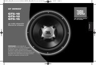
6. Use the 10/24" machine screws and<br />
T-nuts provided to mount the woofer<br />
to the baffle. See Figure 1.<br />
Figure 1. Mounting the GTi woofer in its<br />
enclosure<br />
10/24"<br />
SCREWS<br />
(PROVIDED)<br />
DUAL COIL VERSUS<br />
DIFFERENTIAL DRIVE ® *<br />
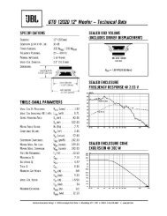
Conventional dual-voice-coil woofers<br />
use a pair of voice coils “interwound” on<br />
the former and centered in the magnetic<br />
gap. The two coils may be connected in<br />
series or parallel in order to maximize an<br />
amplifier’s output power. Both coils drive<br />
the cone forward and rearward. X max<br />
(one-way-linear) is determined by the<br />
amount of voice coil exposed above and<br />
below the top plate. A conventional<br />
voice coil is made up of several layers of<br />
windings, each transferring heat to the<br />
winding next to it until the heat is finally<br />
dissipated by the outside layer through<br />
the top plate, magnet and backplate. This<br />
arrangement is inefficient, and results in<br />
low thermal power handling. See Figure 2.<br />
CONVENTIONAL<br />
Figure DUAL 2. Conventional VOICE COIL dual-voice-coil DESIGN<br />
design<br />
BOTH COILS<br />
DRIVE CONE<br />
FORWARD<br />
AND<br />
REARWARD<br />
CONE<br />
POLEPIECE / BACKPLATE<br />
SPIDER<br />
OVERHANG DETERMINES<br />
X max<br />
TOP PLATE<br />
MAGNET<br />
<strong>JBL</strong> GTi Series subwoofers employ<br />
Differential Drive, a technology<br />
developed by <strong>JBL</strong> Professional.<br />
Differential Drive employs two voice<br />
coils positioned at opposite ends of the<br />
former, each suspended in a separate<br />
magnetic gap. These two coils may be<br />
connected in series or parallel, like a<br />
conventional DVC woofer, to maximize<br />
an amplifier’s output power. Both coils<br />
MUST be connected to the amplifier in<br />
correct polarity! At low power, both<br />
voice coils drive the woofer’s cone, and<br />
any motor nonlinearities are cancelled<br />
by the out-of-phase coils and gaps. As<br />
power input increases so that one coil<br />
rides <strong>com</strong>pletely out of its gap, force is<br />
still applied to the cone by the other coil.<br />
4<br />
T-NUTS<br />
(PROVIDED)<br />
* U.S. patent no. 5,748,760 and other patents pending
CONNECTING YOUR SUBWOOFER TO AN AMPLIFIER<br />
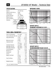
At extremely high power, each coil will<br />
enter the other coil’s magnetic gap. This<br />
will cause magnetic braking, which will<br />
slow the cone’s motion and prevent<br />
damage due to overexcursion. For a<br />
GTi Series woofer, X max is determined<br />
by the amount of voice-coil overhang<br />
between the first and second top plates.<br />
See Figure 3. Thermal power handling is<br />
far superior to a conventional DVC<br />
woofer using voice coils of a similar<br />
diameter and length because Differential<br />
Drive provides twice the heat-dissipating<br />
surface area and two top plates to<br />
transfer heat to the magnet-cover fins.<br />
<strong>JBL</strong><br />
Figure 3. DUAL <strong>JBL</strong> dual-gap GAP DESIGN design<br />
CONFIGURING<br />
THE VOICE COILS<br />
Figure 4. Terminal locations<br />
Note: Unlike conventional DVC<br />
subwoofers, the two sets of terminals<br />
are configured so that both positive (+)<br />
terminals are on one side of the frame<br />
and both negative (–) terminals are on<br />
the other side. GTi Series subwoofers<br />
are shipped with terminal jumpers<br />
installed which configure the two 6-ohm<br />
voice coils in parallel for a 3-ohm load.<br />
Note: Both voice coils MUST be<br />
connected to the amplifier in series<br />
or parallel.<br />
Figure 5. Connecting the voice coils in<br />
parallel (3 ohms)<br />
TERMINAL<br />
JUMPER<br />
INTACT<br />
TERMINAL<br />
JUMPER<br />
INTACT<br />
Figure 6. Connecting the voice coils in<br />
series (12 ohms)<br />
TERMINAL<br />
JUMPER<br />
REMOVED<br />
RED<br />
TERMINAL<br />
+<br />
COILS IN SERIES<br />
12 OHMS<br />
TERMINAL<br />
JUMPER<br />
REMOVED<br />
BLACK<br />
TERMINAL<br />
TOP COIL<br />
IN GAP #1<br />
DRIVES CONE<br />
FORWARD<br />
POLEPIECE<br />
BOTTOM COIL<br />
IN GAP #2<br />
DRIVES CONE<br />
REARWARD<br />
GAP #1<br />
GAP #2<br />
CONE<br />
SPIDER<br />
ALUMINUM<br />
COVER<br />
1st<br />
TOP PLATE<br />
MAGNET<br />
OVERHANG<br />
DETERMINES<br />
X max<br />
2nd<br />
TOP PLATE<br />
RED<br />
TERMINAL<br />
+<br />
BLACK<br />
TERMINAL<br />
COILS IN PARALLEL<br />
Note: Connect the 3 OHMS coils in parallel if you<br />
are connecting a single woofer to an<br />
amplifier.<br />
5
CONFIGURING<br />
MULTIPLE WOOFERS<br />
FOR CONNECTION TO<br />
A SINGLE AMPLIFIER<br />
Figure 7. Connect two woofers in parallel<br />
(with coils in parallel) for a 1.5-ohm load<br />
Figure 8. Connect three woofers in parallel<br />
(with coils in series) for a 4-ohm load<br />
TERMINAL<br />
JUMPER<br />
REMOVED<br />
RED<br />
TERMINAL<br />
TERMINAL<br />
JUMPER<br />
REMOVED<br />
BLACK<br />
TERMINAL<br />
Figure 9. Connect four woofers in parallel<br />
(with coils in series) for a 3-ohm load<br />
TERMINAL<br />
JUMPER<br />
REMOVED<br />
RED<br />
TERMINAL<br />
TERMINAL<br />
JUMPER<br />
REMOVED<br />
BLACK<br />
TERMINAL<br />
TERMINAL<br />
JUMPERS<br />
INTACT<br />
RED<br />
TERMINAL<br />
TERMINAL<br />
JUMPERS<br />
INTACT<br />
BLACK<br />
TERMINAL<br />
+<br />
WOOFERS IN PARALLEL<br />
(COILS IN PARALLEL)<br />
1.5 OHMS<br />
+<br />
WOOFERS IN PARALLEL<br />
(COILS IN SERIES)<br />
4 OHMS<br />
+<br />
WOOFERS IN PARALLEL<br />
(COILS IN SERIES)<br />
3 OHMS<br />
6
SPECIFICATIONS<br />
W10GTi MkII W12GTi MkII W15GTi MkII<br />
10" Automotive subwoofer 12" Automotive subwoofer 15" Automotive subwoofer<br />
Power handling (peak) 3000W 4000W 5000W<br />
Power handling (RMS) 600W 700W 800W<br />
Frequency response (in-car) 20Hz – 1kHz, ±3dB 18Hz – 1kHz, ±3dB 16Hz – 1kHz, ±3dB<br />
Impedance 3 or 12 ohms 3 or 12 ohms 3 or 12 ohms<br />
Sensitivity (2.83V/1m) 90dB 91dB 92dB<br />
Overall diameter 10-1/2" (267mm) 12-1/4" (312mm) 15-1/4" (388mm)<br />
Cutout diameter 9-3/16" (234mm) 11" (280mm) 13-7/8" (353mm)<br />
Mounting depth 9-1/8" (232mm) 10-1/4" (260mm) 10-1/4" (260mm)<br />
Basket displacement .108 cu. ft. (3.06 L) .149 cu. ft. (4.23 L) .174 cu. ft. (4.93 L)<br />
GENERAL CARE<br />
The loudspeaker grilles may be cleaned with a damp cloth. Do not use any cleaners or solvents on the grilles or the speaker cones.<br />
These products are designed for mobile applications and are not intended for connection to the mains.<br />
A valid serial number is required for warranty coverage.<br />
Features, specifications and appearance are subject to change without notice.<br />
Not all models are available in all markets.<br />
7
Declaration of Conformity<br />
<strong>JBL</strong> Consumer Products<br />
250 Crossways Park Drive, Woodbury, NY 11797 USA<br />
516.255.4<strong>JBL</strong> (4525) (USA only) www.jbl.<strong>com</strong><br />
© 2006 Harman International Industries, Incorporated. All rights reserved.<br />
<strong>JBL</strong> and Harman International are registered trademarks of Harman International<br />
Industries, Incorporated.<br />
Dacron is a registered trademark of Invista.<br />
Part No. W10/12/15GTIOM1/06<br />
We, Harman Consumer Group International<br />
2, route de Tours<br />
72500 Château du Loir<br />
France<br />
declare in own responsibility that the products described in this owner’s<br />
manual are in <strong>com</strong>pliance with technical standards:<br />
EN 61000-6-3:2001<br />
EN 61000-6-1:2001<br />
Klaus Lebherz<br />
Harman Consumer Group International<br />
Château du Loir, France 1/06<br />
www.jbl.<strong>com</strong>