Hydraulic Rotary Actuators
Hydraulic Rotary Actuators
Hydraulic Rotary Actuators

Create successful ePaper yourself
Turn your PDF publications into a flip-book with our unique Google optimized e-Paper software.
VOL. 9<br />
REV. 06/07<br />
FORMULAS<br />
E-1 – E-6<br />
FLOW RATE CHART<br />
E-15 & E-16<br />
GUIDE TO SIZE<br />
E-17 & E-18<br />
PAGES<br />
E-1 – E-19<br />
Engineering<br />
Data<br />
PAGES<br />
MP-1 – MP-4<br />
Mid-Pressure<br />
Model MP<br />
PAGES<br />
SS-1 – SS-4<br />
High Pressure<br />
Solid Shaft<br />
PAGES<br />
HS-1 – HS-4<br />
High Pressure<br />
Hollow Shaft<br />
PAGES<br />
R-1 – R-4<br />
Rotating<br />
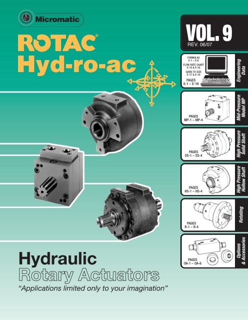
<strong>Hydraulic</strong><br />
<strong>Rotary</strong> <strong>Actuators</strong><br />
“Applications limited only to your imagination”<br />
PAGES<br />
OA-1 – OA-6<br />
Options<br />
& Accessories
W<br />
elcome to the world of rotary motion. We appreciate<br />
your interest and are pleased to offer you our catalog,<br />
featuring Micromatic’s extensive line of rotary actuators.<br />
Micromatic actuators have earned worldwide renown under<br />
the trade names of Rotac and Hyd-ro-ac.<br />
Micromatic, long recognized as an industry leader, has<br />
been designing and manufacturing rotary actuators<br />
for over forty years.<br />
Micromatic provides actuators with either hydraulic or<br />
pneumatic capability. Your imagination alone limits the<br />
number of possible applications.<br />
We offer true “A to Z” capability. Our standard units<br />
produce up to 700,000 in. lbs. of torque @ 3000 PSI,<br />
and we have designed “specials” with 4,500,000 in. lbs.<br />
@ 2200 PSI capability.<br />
If your application requires an actuator outside the range<br />
of our standard line, our seasoned product design and<br />
application engineering group will modify and/or design a<br />
specialty actuator to suit your needs.<br />
Give your Micromatic distributor a call, and let our sales<br />
team help you make your equipment the very best possible.<br />
3<br />
10-97
Applications<br />
1 Product: Back Hoes<br />
Actuator Used: SS Series<br />
Application: Back Hoe Swing<br />
2 Product: Boat Launch<br />
Actuator Used: HS Series<br />
Application: Davit Swing<br />
1<br />
3 Product: Wheelchair Lift<br />
Actuator Used: Special<br />
Application: Raise and Lower<br />
Wheelchair Platform<br />
2<br />
3<br />
4<br />
10-97
4 Product: Log Loaders<br />
Actuator Used: SS Series and HS Series<br />
Application: Boom Swing and Grapple Swing<br />
4<br />
5 Product: Container Loading Systems<br />
Actuator Used: HS Series<br />
Application: Positioning Guides<br />
6 Product: Paint Spraying Robot<br />
Actuator Used: MP Series<br />
Application: Rotate Spray Head<br />
7 Product: Brake Rotor Gage<br />
Actuator Used: MP Series<br />
Application: Parts Transfer<br />
5<br />
6<br />
7<br />
5<br />
06-02
Applications (Cont’d)<br />
8 Product: Animated Character<br />
Actuator Used: MP Series<br />
Application: Animated Character<br />
Joint Movement (Muscle)<br />
8<br />
9 Product: <strong>Hydraulic</strong> Lift<br />
Actuator Used: HS-10 and HS-15<br />
Application: Residential and Commercial<br />
Refuse Handling System<br />
10 Product: Automated Machinery<br />
Actuator Used: MP Series<br />
Application: Parts Transfer<br />
9<br />
11 Product: Truck Mounted Booms<br />
Actuator Used: SS Series and HS Series<br />
Application: Boom Swing<br />
and Grapple Swing<br />
10<br />
11<br />
6<br />
06-02
12 Product: Printing Presses<br />
Actuator Used: SS Series<br />
Application: Tensioning Device<br />
12<br />
13 Product: Press Brakes<br />
Actuator Used: HS Series<br />
Application: Press Brake Drive<br />
14 Product: Tube and Pipe Bender<br />
Actuator Used: SS Series<br />
Application: Tube Bending Drive<br />
13<br />
15 Product: Highway Maintenance Equipment<br />
Actuator Used: HS Series<br />
Application: Spraying Boom Swing<br />
14<br />
15<br />
7<br />
06-02
ENGINEERING DATA<br />
THE BASICS<br />
<strong>Rotary</strong> actuators convert fluid pressure into rotary power, and develop<br />
instant torque in either direction. Basic construction consists of an<br />
enclosed cylindrical chamber containing a stationary barrier and a<br />
central shaft with vane(s) affixed. Fluid pressure applied to either side<br />
of the vane will cause the shaft to rotate.<br />
POSSIBLE APPLICATIONS<br />
<strong>Rotary</strong> actuators are adaptable to a wide variety of uses in many<br />
different industries. The sketches shown give only an idea of the various<br />
possibilities. <strong>Actuators</strong> can perform a wide range of operations involving<br />
rotary or linear motion.<br />
TOGGLE — BEND TWIST<br />
PUSH — CLAMP<br />
The output torque developed is determined by the area of the vane,<br />
the number of vanes, and the fluid pressure applied. Speed of rotation is<br />
dependent on the flow and pressure capacities of the hydraulic system.<br />
The majority of actuators are constructed with one or two vanes, but are<br />
available with three or more for special applications. The theoretical<br />
torque output of a multivane unit is greater by a factor equal to the<br />
number of vanes times the torque of a single vane unit at equal<br />
pressure. The maximum arc of rotation for any actuator depends on the<br />
size and construction of the unit, and will always be less than the<br />
number of vanes divided into 360° because of the space occupied by<br />
the internal barrier(s). The arc of a single vane is approximately 280°, a<br />
double vane 100° and a triple vane 50°.<br />
VERSATILITY<br />
Fluid Media — <strong>Actuators</strong> can be operated on either pneumatic<br />
or hydraulic pressure. The fluid can be air, oil, high water base fluid<br />
(HWBF), or fire resistant fluid. <strong>Actuators</strong> can be assembled with<br />
special seals and/or internally plated for specific fluids.<br />
Mounting — <strong>Actuators</strong> can be mounted horizontally, vertically or<br />
any angle in between. Models are available with flange, end, base<br />
or foot mounting provisions.<br />
<strong>Actuators</strong> are usually mounted in a stationary position with the shaft<br />
rotating, but also can be shaft mounted with the housing portion rotating.<br />
Some models require mounting dowels to resist torsional forces.<br />
See the specific actuator model for mounting details.<br />
TYPICAL MOUNTINGS<br />
Control — Stopping, starting, acceleration and deceleration of<br />
actuators can be controlled by various types of valves in the fluid circuit.<br />
External stops are recommended for most applications,<br />
although the arc of oscillation can be controlled by valves or positive<br />
internal stops (for light duty applications only).<br />
In most cases special manifolds can be designed to mount servovalves<br />
to the actuators allowing sophisticated control of all functions.<br />
TURN — OSCILLATE CONTINUOUS ROTATION INDEX — POSITION<br />
MATERIAL HANDLING MIX — STIR AUTOMATION TRANSFER<br />
LOAD — CONVEYOR TURN — STOP INTERMITTENT FEED<br />
POSITION — UNLOAD<br />
TURNOVER — DUMP VALVE OPEN — CLOSE LIFT — ROTATE<br />
— — — AND MANY OTHERS<br />
FACTORS TO CONSIDER WHEN<br />
APPLYING ACTUATORS<br />
Service<br />
Light Load — Heavy Load — consider weight of load and distance<br />
from actuator shaft.<br />
Bearing Loads — heavy radial loads without external bearing support.<br />
Shock Loads — consider dropped loads or mechanical failure of<br />
associated equipment. Also start - stop - jog and other non mechanical<br />
contact, hydraulic shock loads.<br />
Rate of Oscillation — time to move load thru required angle. Also<br />
consider small angle - high rate applications.<br />
Cycle Frequency — how often actuator is cycled. One cycle per<br />
minute, one cycle per week, etc.<br />
External Stops — external stops should be used to limit<br />
angular travel as the actuator abutments (shoes) are not designed<br />
as mechanical stops.<br />
Operating Press — should not exceed rated pressure of actuator.<br />
E-1<br />
1-94
ENGINEERING DATA<br />
Environmental<br />
Temperature — Hot example – foundry applications.<br />
Cold example – cryogenic equip, outdoor equip.<br />
Dirt — Examples, foundries, construction equipment<br />
Caustic — Examples, valve operators, mixers plating tanks<br />
Humidity — marine applications, outdoor<br />
Vibration — machine tools, test equipment<br />
Radiation — nuclear energy plants<br />
Electricity — welding equipment<br />
Clean — food processing, medical equipment<br />
Maintenance<br />
Lubrication — consult factory<br />
Filter Maintenance — especially foundry and construction<br />
type applications<br />
Shaft Alignment — close tolerance alignment or flexible couplings<br />
Proper Mounting — rigid support, tight bolts, good coupling fits<br />
Long Term Storage — fill with compatible oil<br />
External Stops — tightness and proper location<br />
Fluid Media Conditioning — water separators, lubricators, oil coolers<br />
Fittings and Hoses — tightness and general condition<br />
Protective Shielding — for high temperature or excessively<br />
dirty applications<br />
GENERAL ENGINEERING NOTES<br />
Selection of the proper sized actuator for an application is<br />
accomplished by determining the necessary torque to move the load<br />
at the required speed, the available fluid pressure and the necessary<br />
arc of rotation. Good design practice dictates a nominal over – capacity<br />
be designed into the load moving system.<br />
Load torque, T L (inch pounds) is the resistance to movement of the<br />
shaft due to a load force or mass, M,<br />
(pounds) acting at a distance, R,<br />
(inches) from the center of the shaft<br />
rotation. T L =MR.<br />
Motion will occur when the applied<br />
torque of the actuator exceeds the load<br />
torque. The velocity and acceleration, A,<br />
given to the load mass, M, is proportional<br />
to the excess torque or force, F.<br />
A= F M<br />
or<br />
F=MA<br />
Similarly, the load mass once set in<br />
motion must be stopped or decelerated<br />
with an opposing force F=MA. This<br />
deceleration force can be obtained by<br />
gradually restricting the flow of fluid to<br />
and from the actuator.<br />
Caution:<br />
Actuator should be protected from over pressurization during deceleration.<br />
Lifting a mass in an arc causes the effective radius ER, to vary with<br />
the rotational position, becoming minimum at the vertical (90°) position.<br />
The load torque due to load force thus decreases from maximum<br />
at position 1 to minimum at position 2, and then reverses to aid rotation<br />
from position 2 to position 3. Restrictions of fluid flow and control<br />
of deceleration pressures is vitally necessary in this type of application.<br />
Calculation of the amount and rate of energy dissipation required to<br />
stop a moving mass is possible if the variables such as velocity, mass,<br />
time, pressure, viscosity, etc., can be determined. In actual circuits<br />
these factors are inter-related and solution is often complex.<br />
Good general practice requires that more cycle time be allowed for<br />
deceleration than for acceleration of a given mass.<br />
A simplified calculation can be made if the assumption is made that<br />
the acceleration and deceleration are constant and uniform. The energy<br />
required to accelerate the mass must be equal to the energy to<br />
decelerate the mass. This simplifies to the following formulas:<br />
Pressure (PSI accel) times Pressure (PSI accel) times<br />
Rotation (Degrees accel)= Time accel=<br />
OR<br />
Pressure (PSI decel) times Pressure (PSI decel) times<br />
Rotation (Degrees decel)<br />
Time decel<br />
Example:<br />
A mass accelerated uniformly for<br />
50° @ 800 psi moves at constant<br />
velocity through use of flow-control<br />
valves until decelerated in the last<br />
100° in 10 seconds @ 400 psi.<br />
Note, however, that if the driving<br />
pressure were not removed during<br />
the deceleration period, the total deceleration pressure would be the sum of<br />
pressures, and at 1,200 psi could exceed the rating of the unit.<br />
Actuator distributors can provide valuable assistance in solving specific<br />
circuit and application problems.<br />
Direction and speed control for slow speed and light loading<br />
applications can be accomplished with relatively simple fluid circuits using<br />
hand- operated 4-way valves.<br />
High speed and/or rapid cycling operation would suggest a commercially<br />
available solenoid-operated 4-way directional control valve and flow-control valves<br />
for better control of cycle motions, and the addition of fluid cooler, accumulators,<br />
and other components directed to specific system requirements.<br />
Severe shock and possible damage to the system can occur on hydraulic<br />
applications by sudden or complete restriction of outgoing fluid, which allows<br />
the moving mass to generate high surge or transient shock wave pressures<br />
which must not exceed the rating of the unit.<br />
E-2<br />
4-96<br />
Engineering<br />
Data
ENGINEERING DATA<br />
Deceleration valves, actuated by cams or by limit switches, are often<br />
used to gradually restrict the fluid and stop the moving mass. Usually,<br />
relief valves plumbed as shown, or plumbed from one line to the other in<br />
each direction, will limit the generation of surge pressures to a safe<br />
value. Cross-port relief manifolds are available for most actuators. If cam<br />
valves are used, the cam shape should provide a gentle ramp transition,<br />
and the spool should be tapered to provide a gradual closing off of fluid.<br />
As a general rule, external stops, mounted securely to the<br />
machine framework, should be used to stop the load. The shaft<br />
vanes should not contact the internal stops except under very<br />
light loads.<br />
Air bleeding in hydraulic systems is usually not required if actuator is<br />
mounted with supply ports upward. In other positions, air will gradually<br />
dissolve in the oil and be carried away as the actuator is cycled. Special<br />
bleed connections are available as an optional feature on some<br />
actuators if specified when ordering.<br />
Internal by-pass flow is always present to a small degree, and<br />
increases with increase of pressure. On air applications it must be<br />
recognized that on stall-out applications, under air pressure, there will<br />
be a small continuous by-pass flow.<br />
Pure torque out-put from the actuator without external radial shaft<br />
bending loads is preferred to allow maximum bearing life. An arrangement<br />
with a semi-flexible coupling and the load shaft supported by<br />
separate bearings is recommended.<br />
A similar arrangement is advised for power transmission through<br />
gears to eliminate gear load and separating forces from aggravating the<br />
actuator bearing load.<br />
Where a flexible coupling cannot be<br />
used, very accurate alignment of the<br />
actuator and associated equipment is<br />
essential to prevent undue actuator<br />
bearing loading.<br />
End thrust or axial loading of the<br />
actuator shaft is not advised. A thrust<br />
bearing, and the load driven through a<br />
sliding spline (or other means)<br />
is recommended to minimize internal<br />
wear for maximum actuator life.<br />
Temperature:<br />
Standard actuators, unless otherwise specified, may be operated<br />
satisfactorily between minus 30°F and plus 250°F. Operation at higher<br />
temperatures requires special seal compounds.<br />
E-3<br />
4-96<br />
Filtration:<br />
Filtration of operating fluid to the 25 micron range is recommended.<br />
Storage:<br />
<strong>Actuators</strong>, when stored for any extended period of time, will require<br />
additional rust protection. Upon receipt of the actuator, remove port<br />
plugs, fill the actuator chambers with clean, mineral-base oil (or other<br />
fluid compatible with seal compounds), and replace plugs securely.<br />
Cover exterior surfaces with adequate rust-preventive material. Place in<br />
a poly bag and seal.<br />
Installation:<br />
Normal machinists’ practice and care should be used in installing<br />
actuators. As for any oscillating type actuator, the most efficient means<br />
of transmitting the torque developed is through multiple tooth, involute<br />
spline or SAE 10-B spline. Suitable flange type adapters and straight<br />
connectors are covered under “Accessories” in the catalog. These are<br />
also available through the local distributor.<br />
System Pressure:<br />
Caution must be exercised in actuator sizing by making allowance for<br />
a pressure drop throughout the hydraulic system in which the actuator is<br />
installed. If an extensive system of piping, control valves, flow control<br />
valves, etc. is present, it is to be expected that full line pressure will not<br />
be available at the actuator inlet port.<br />
Angular Velocity:<br />
Angular velocity can be readily controlled by metering the amount of<br />
flow of fluid into or out of the actuator ports. Many designs of flow<br />
control valves are available on the market for this purpose. If greater<br />
flow is required than that available in the selected standard actuator,<br />
special larger size ports can be specified within reasonable limits.<br />
Service and Repair:<br />
Seals in actuators are readily replaced by qualified personnel trained in<br />
hydraulic equipment repair. Interchangeable replacement parts are available<br />
from factory. Always specify the serial number and bill of material of unit<br />
when ordering spare or replacement parts. Replacement of worn bearings<br />
may be accomplished by qualified personnel, but we recommend that such<br />
repairs be made by the Factory Repair Department so that units can be<br />
reconditioned to meet original performance specifications.<br />
Distributors in principal cities throughout the U.S., Canada, Europe,<br />
and Asia can supply you with additional information. If you have any<br />
questions, contact your distributor, or the actuator factory.<br />
An overhaul procedure which contains complete instructions for<br />
replacement of seals or other worn parts, and an exploded view and<br />
parts list for ordering replacement parts, is available from the factory.<br />
Service operations should be performed by competent hydraulic<br />
equipment technicians to maintain high manufacturing quality standards.<br />
Basic Formulas (<strong>Hydraulic</strong>)<br />
L = Body Length (in.)<br />
D = Body I.D. (in.)<br />
d = Hub dia. (in.)<br />
ARC = Degrees of Rotation<br />
N = Number of Vanes<br />
PSI = Lbs/Sq. Inch (Pressure)<br />
Displacement Per Radian = [N•L(D 2 – d 2 )]÷8 (in 3 /Rad.)<br />
Theoretical Torque = [N•L(D 2 – d 2 )÷8]PSI (in-lb)<br />
Actual Torque = Theoretical Torque •% efficiency (in-lb)<br />
Total Displacement = [L•ARC•N•π (D 2 – d 2 )]÷1440 (in 3 )
ENGINEERING DATA<br />
HARMONIC MOTION DRIVES<br />
Applications requiring the linear transfer of a load under controlled<br />
acceleration and deceleration are quite common. Within limits, this type<br />
of motion can be achieved thru a harmonic motion drive. An actuator<br />
driven, scotch yoke arrangement as shown in Figure 1 imparts this<br />
type motion. The scotch yoke converts the constant speed rotating<br />
motion to a sinusoidal motion producing maximum linear force for<br />
acceleration, maximum linear speed thru the middle of the actuator<br />
stroke, and maximum decelerating forces to slow and stop the load.<br />
The following equations assume a constant actuator rotational<br />
velocity. This is sometimes difficult to achieve, particularly for short<br />
cycle times that result in a large load velocity. The inertia of the load<br />
will tend to drive the actuator during the deceleration phase. These<br />
forces may cause cavitation or physical damage to the actuator.<br />
Therefore, under certain conditions the actuator may require external<br />
assistance in decelerating the load.<br />
A flow control in the discharge side of the actuator provides this<br />
assistance, assuring a positive-pressure throughout the cycle. The<br />
added resisting torque resulting from the discharge metering must be<br />
added to the driving torque requirement.<br />
Equations of Motion<br />
The equation of motion for a Scotch Yoke mechanism can be<br />
developed as follows:<br />
Referring to Figure 1.<br />
(1) s=r cosθ<br />
and<br />
(2) θ=ωt<br />
Where<br />
ω = angular velocity of crank (link 1). rad<br />
t=time, sec.<br />
sec.<br />
r=crank length, in.<br />
s=horizontal movement of load W from midpoint of travel, in.<br />
The velocity of link 2, and thus load W, may be found by differentiating<br />
the movement with respect to time.<br />
(3) v = d(–s) = d(–r cos ωt) =rω sin ωt<br />
dt dt<br />
The acceleration of load W is found by differentiating its velocity with<br />
respect to time:<br />
(4) a = dv = d(rω sin ωt) =rω 2 cos ωt<br />
dt dt<br />
Therefore, when the crank rotates at constant angular velocity, the velocity<br />
and acceleration of the load can be determined for any position of the<br />
crank. Equation (4) indicates that maximum acceleration occurs when<br />
cos ωt = 1 or<br />
(5) a max. =rω 2<br />
For a 180° crank throw, ω =<br />
π<br />
, where t’ represents the time<br />
t’<br />
required to transfer the load a distance of 2r. Therefore,<br />
(6) a max. =r ( π ) 2<br />
t’<br />
This relation applies for any load W.<br />
FIGURE 1. TYPICAL HARMONIC MOTION DRIVE ARRANGEMENT<br />
Required Torque<br />
Consider an actuator powered Scotch Yoke mechanism moving a<br />
load as shown in Figure 1. Assume for simplicity that the system is<br />
frictionless. The forces acting on the actuator crank (link 1) are also<br />
shown in Figure 1.<br />
(7) P = W a= W (rω 2 cos ωt)<br />
g g<br />
Therefore, the required actuator torque at any time during the cycle is:<br />
The maximum torque requirement may be found by differentiating<br />
equation (10) with respect to time and setting the result equal to 0 as<br />
follows:<br />
(11) dT = Wr 2 ω 2 d(cosωt sin ωt) =0<br />
dt g dt<br />
Since sin 2 ωt = 1 – cos 2 ωt, substitution into equation (11) yields<br />
cos 2 ωt = 0.5<br />
or<br />
cosωt = sinωt = 0.5<br />
Therefore, the maximum actuator torque requirement is:<br />
π<br />
Recalling that ω =<br />
t’<br />
and g = 386.4 in/sec 2<br />
(8) F = W (rω 2 cos ωt) (sin ωt)<br />
g<br />
(9) R = W (rω 2 cos 2 ωt)<br />
g<br />
(10) T = (F)r = Wr 2 ω 2 (cos ωt) (sin ωt)<br />
g<br />
(12) T max. = (.5)<br />
Wr 2 ω 2 [ωcos 2 ωt – ωsin 2 ωt] =0<br />
g<br />
Wr 2 ω 2<br />
g<br />
(t’ = time for 180° crank throw)<br />
(13) T max. = (.5)( π) 2 XW( r ) 2 = .01277W<br />
( r ) 2 IN-LB with r measured<br />
386.4 t’ t’ in inches.<br />
This expression may be used to determine the maximum actuator<br />
torque requirement for a frictionless system by knowing the load weight,<br />
crank arm length and the time required for 180º crank rotation.<br />
In systems where friction must be considered, the required actuator<br />
torque will obviously be greater than that given by equation 13. The<br />
derivation of torque equations which consider the effects of friction<br />
becomes somewhat mathematically involved and will therefore not be<br />
repeated here.<br />
E-4<br />
4-96<br />
Engineering<br />
Data
ENGINEERING DATA<br />
However, by considering only friction of the moving load and neglecting<br />
the crank friction forces along the vertical axis (vertical friction forces<br />
have little effect on torque) it can be shown that the maximum actuator<br />
torque is approximately:<br />
(14) T max. = Wr[.02554 r cosωt + µ]sin ωt, in-lb<br />
(t’) 2<br />
r r 2<br />
ROTATIONAL SPEED OF<br />
ACTUATORS/PUMP CAPACITY<br />
REQUIRED<br />
For hydraulic operation the time necessary for the actuator to make<br />
its travel arc can be figured with reasonable accuracy.<br />
Where:<br />
Arc=amount of rotation required (in degrees).<br />
t=time, in seconds, for the actuator to make its arc of rotation.<br />
Av=Angular velocity, in degrees per minute, for the actuator to make its<br />
arc of rotation.<br />
Da=displacement, in cubic inches per radian, of the actuator.<br />
GPM=gallons per minute required to rotate the actuator the specified<br />
arc in the specified time.<br />
t = 60•Arc<br />
Av<br />
Example:<br />
Calculate the time necessary to rotate an actuator 100°, that<br />
displaces 3.78 cubic inches per radian, with a five gallon per minute<br />
fluid supply.<br />
Av = 13235•GPM = 13235•5 17506.6 degrees per<br />
=<br />
Da 3.78 minute<br />
Using the same basic formula, the GPM required to rotate an actuator a<br />
specified arc in a specified time can be figured.<br />
Example:<br />
Calculate the necessary pump capacity required to rotate an actuator<br />
that displaces 10.9 cubic inches per radian, 180° in .5 seconds.<br />
SAMPLE PROBLEMS<br />
A few typical Rotac application problems are presented here along<br />
with simplified solutions which can be used to approximate the torque<br />
requirement for a specific job. These formulas should be used only as a<br />
guide in the selection of an actuator since friction and other system<br />
characteristics are not considered.<br />
E-5<br />
2-90<br />
where µ = coefficient of friction of moving load<br />
ωt = cos -1 {–9.788 µ(t’) 2 + .25 [1532.76 µ 2 (t’) 4 + 8] 1/2 }<br />
Av = 13235•GPM<br />
Da<br />
t = 60•Arc = 60•100 = .343 seconds<br />
Av 17506.6<br />
GPM =<br />
Da x Av<br />
13235<br />
Av = 60•Arc = 60•180° = 21,600 degrees per minute<br />
t .5<br />
GPM = Da•Av = 10.9•21,600 = 17.79 Gallons per minute<br />
13235 13235<br />
The symbols used in the sample problems are defined as follows:<br />
a, b, Dimensional Characteristics of Load, IN.<br />
F Force, LB.<br />
g Acceleration of Gravity, (386.4 IN./SEC. 2 )<br />
Jm Polar (mass) Moment of Inertia, in-lb sec 2<br />
r Radius, IN. (to the center of gravity of the weight)<br />
t Time, Sec. (per stroke or 1 /2 cycle)<br />
T Torque, IN.-LB.<br />
m Mass of Load (Weight ÷ 386.4)<br />
α Angular Acceleration, RAD./SEC. 2<br />
θ Angular movement in radians (degrees per stroke ÷ 57.3)<br />
Problem #1<br />
Find the torque required to rotate a rectangular load (horizontally) thru a<br />
given arc in a specified time. (See fig. 1)<br />
Solution:<br />
T = ∑ Jmα<br />
∑ Jm = Jm 1<br />
+ Jm 2<br />
. . . The sum of all polar mass moments of inertia<br />
being rotated.<br />
Jm 1<br />
≅ m 1<br />
r 1<br />
2 (for applications where r is large in comparison to a & b)<br />
Jm 2<br />
=<br />
m 2 2 (for a straight rod or any straight symmetrical shape)<br />
3<br />
α = 4θ (assumes 50% of rotating time for acceleration and 50%<br />
t 2 for deceleration)<br />
Example #1<br />
Find the torque necessary to rotate a 20 lb. weight, 160°, in .5 seconds.<br />
The weight is supported by a 36" long, 3 lb. rod. (a & b are 8.4 inches)<br />
(r 1<br />
= 40.2 inches)<br />
Jm 1<br />
≅ m 1<br />
r 2<br />
1<br />
=<br />
20<br />
(40.2) 2 = 83.64 in-lb sec<br />
386.4<br />
2<br />
Jm 2<br />
= m 2 2 = [3÷(386.4)]36 2 = 3.35 in-lb sec 2<br />
3 3<br />
160°<br />
θ = 57.3° = 2.792 radians<br />
α 4θ 4(2.792)<br />
= = = 44.67 radians / sec.<br />
2<br />
t 2<br />
.5 2 ( a2 + b 2 +r 2 )<br />
T = ∑ Jmα = (Jm 1<br />
+ Jm 2<br />
)α = (83.64 + 3.35)44.67 = 3885 in-lb of<br />
torque required<br />
Note: If r 1<br />
is small in relation to a & b use: Jm 1<br />
= m 1<br />
12
ENGINEERING DATA<br />
Example #2<br />
(assume r 1<br />
in example #1=12" all other parameters remain the same)<br />
( a2 + b 2 +r<br />
12 1<br />
2) ( 8.42 + 8.4 2 + 12 2)<br />
Jm 1<br />
= m 1 =<br />
20<br />
=8.06 in-lb sec<br />
386.4 12<br />
2<br />
= r 1<br />
– (a÷2) = 12 – (8.4÷2) = 7.8<br />
Jm 2<br />
= m 2 [3÷ (386.4)]7.8 2<br />
2<br />
3 3<br />
α = same as previous (44.67)<br />
= .157 in-lb sec 2<br />
T = ∑Jmα = (Jm 1<br />
+ Jm 2<br />
)α = (8.06 + .157) 44.67<br />
= 367 in-lb of torque required<br />
Problem 2:<br />
Find the torque required to rotate a thin hollow pipe about its transverse<br />
axis through a given angle in a specified time.<br />
Engineering<br />
Data<br />
Problem 1A:<br />
Find the torque required to lift a weight and rotate it vertically thru a<br />
specified arc in a specified time.<br />
Solution:<br />
T =∑(Jmα + (Wr cosθ s<br />
))<br />
Solution:<br />
Assume:<br />
T = Jmα = (Jm c + Jm p ) α<br />
For thin-walled pipe<br />
Jm p = m (r p<br />
2 + p 2 )<br />
2 6<br />
For thick-walled pipe<br />
Jm p = m (R p<br />
2 + r p<br />
2 + p 2 )<br />
4 3<br />
For solid-circular bar<br />
Jm c = m (3r c<br />
2 + c<br />
2 )<br />
12<br />
50% ( t ) for acceleration<br />
50% ( t ) for deceleration<br />
FIGURE 2<br />
Note: Jmα is the torque required to move the load without the effect<br />
of gravity.<br />
Wr cosθ is the torque resulting from the effect of gravity on the load.<br />
The torque required changes as the angle changes, the maximum<br />
requirement at horizontal, lessening to zero at the vertical. The torque<br />
value is negative past vertical, gravitational forces actually aiding in<br />
producing torque.<br />
Example #3<br />
Find the torque required if the load in example # 1 is rotated vertically.<br />
Assume the starting angle (θ S<br />
) is 20°.<br />
Assume:<br />
Jmα = T = 3885 in.-lb. (from example #1) W 1<br />
= 20 lb., W 2<br />
= 3 lb.,<br />
r 1<br />
= 40.2, r 2<br />
= 20.1<br />
T = ∑ (Jmα + (w 1 r 1 + w 2 r 2 )cos θ S<br />
)<br />
= 3885 + (20 •40.2 + 3 •20.1) cos 20° = 4697 in.-lb. required at start.<br />
Tmax = ∑ [Jm∝ + (w 1 r 1 + w 2 r 2 )]<br />
= [3885 + (20•40.2 + 3•20.1)] = 4749 in-lb<br />
Therefore,<br />
Example:<br />
Assume:<br />
α = 4θ<br />
t 2<br />
Carrier: — 1" dia. x 12" long steel bar (2.7 Lb.)<br />
Pipe: — 2.88 I.D. x 3.00 O.D. x 36" long (steel) (6 Lb.)<br />
Rotate pipe 180° in 2 secs.<br />
m =<br />
W<br />
386.4<br />
T = (Jmp = Jmc) α<br />
Jmp =m (rp 2 + p 2 ) = .0155 (1.44 2 + 36 2 ) = 1.690 in-lb sec 2<br />
2 6 2 6<br />
Jmc =m (3rc 2 + c 2 ) = .007 (3(.5) 2 + 12 2 ) = .084 in-lb sec 2<br />
12 12<br />
α = 4θ = 4(180÷57.3) = 4(3.14) = 3.14 rad/sec. 2<br />
t 2 2 2 4<br />
T = (1.690 + .084) 3.14 = 5.57 in.-lb. torque required<br />
E-6<br />
4-96
ENGINEERING DATA<br />
Problem 3:<br />
Find the torque required to open or close a door through a given angle<br />
in a specified time.<br />
Problem 4:<br />
Find the torque required to rotate several plates of various thicknesses<br />
through a given angle in a specified time.<br />
Solution:<br />
T= Jm C L Rotation α = ∑ [(Jm 1 + Jm 2 + Jm 3 ) α + (w 1 r 1 +w 2 r 2 + w 3 r 3 )]<br />
M 1<br />
Jm 1 = (a 1<br />
2+ b 1<br />
2) + m 1 r 2<br />
12<br />
1<br />
Solution:<br />
Assume:<br />
Therefore,<br />
T = Jm CL hinge α<br />
JmA-A = m (a 2 + b 2 )<br />
12<br />
Jm CL hinge = JmA-A + mr 2<br />
50% ( t ) for acceleration<br />
50% ( t ) for deceleration<br />
α = 4θ<br />
t 2<br />
Example:<br />
Find the torque necessary to open a 350 Lb. door 100° in .8 secs.<br />
Assume:<br />
door: a = 4", b = 36", r = 22", w = 350 Lb.<br />
m =<br />
W<br />
386.4<br />
T = Jm CL hinge α<br />
JmA-A = m (a 2 + b 2 ) = .906 (4 2 + 36 2 ) = 99.06 in-lb sec 2<br />
12 12<br />
Jm C L hinge = JmA-A + (mr 2 ) = 99.06 + (.906 (22 2 )) = 537.56 in-lb sec 2<br />
α = 4θ = 4(100÷57.3) = 6.98 = 10.91 rad./sec 2<br />
t 2 .8 2 .64<br />
T = Jm C L hinge α = 537.56 (10.91) = 5864. 12 in-lb. torque required<br />
Assume:<br />
Therefore,<br />
α = 4θ<br />
t 2<br />
Jm 2 = (a 2<br />
2+ b 2<br />
2) + m 2 r 2<br />
12<br />
2<br />
Jm 3 = (a 3<br />
2+ b 3<br />
2) + m 3 r 2<br />
12<br />
3<br />
50% (t) for acceleration<br />
50% (t) for deceleration<br />
Example:<br />
Rotate three plates as shown, 180º in 2 secs.<br />
Assume:<br />
w 1 : a 1 =.5", b 1 =6" weight=10 Lb., r 1 =5.25<br />
w 2 : a 2 =5", b 2 =6" weight=100 Lb., r 2 =2.5<br />
w 3 : a 3 =2", b 3 =6" weight=40 Lb., r 3 =1.0<br />
m =<br />
M 2<br />
M 3<br />
W<br />
386.4<br />
T= Jm C L Rotation α = ∑ (Jm 1 + Jm 2 + Jm 3 ) α<br />
Jm 1 = m 1 (a 1<br />
2 + b 1<br />
2) + m 1 r 1<br />
2 = .026 (.5 2 + 6 2 ) + .026 (5.25) 2<br />
12 12<br />
= .795 in-lb sec 2<br />
Jm 2 = m 1 (a 2<br />
2 + b 2<br />
2) + m 2 r 2<br />
2 = .259 (5 2 + 6 2 ) + .259 (2.5) 2<br />
12 12<br />
= 2.94 in-lb sec 2<br />
Jm 3 = m 3 (a 3<br />
2 + b 3<br />
2) + m 3 r 3<br />
2 = .104 (2 2 + 6 2 ) + .104 (1.0) 2<br />
12 12<br />
= .451 in-lb sec 2<br />
α = 4θ = 4(180÷57.3) = 4(3.14) = 3.14 rad/sec.2<br />
t 2 2 2 4<br />
T= ∑ [(Jm 1 + Jm 2 + Jm 3 ) α + (w 1 r 1 + w 2 r 2 +w 3 r 3 )]<br />
=[ (.795 + 2.94 + .451) 3.14 + (10 x 5.25 + 100 x 2.5 + 40 x 1)]<br />
= 355.64 in-lb torque required<br />
E-7<br />
3-93
ENGINEERING DATA<br />
Problem 5:<br />
Find the torque required to produce a given force as shown in the<br />
figure below.<br />
Problem 6:<br />
Find the torque required to produce a given force in a typical die<br />
closer application.<br />
Engineering<br />
Data<br />
Solution:<br />
T =<br />
[<br />
Fr sin (θ 1 + θ 2 )<br />
cosθ1 ]<br />
Design Notes:<br />
1. The design should be such that angles θ 1 and θ 2 are not permitted<br />
to go to zero degrees.<br />
Solution:<br />
T =<br />
[<br />
2Fr sin (θ 1 + θ 2<br />
)<br />
cosθ1 ]<br />
Design Notes:<br />
1. The design should be such that angles θ 1 and θ 2 are not permitted<br />
to go to zero degrees.<br />
2. Force, F, must be less than the bearing capacity of the actuator.<br />
REFERENCE DATA<br />
PROPERTIES OF VARIOUS SOLIDS*<br />
Polar mass<br />
Solids Moment of inertia, Jm Radius of gyration, K<br />
J AA = m 2<br />
12<br />
J BB = m 2<br />
3<br />
J CC = m 2 sin 2 α<br />
3<br />
2. Force, F, may be greater than the bearing capacity of the actuator<br />
since it is transmitted through the linkage, and not to the bearing.<br />
K AA = .<br />
12<br />
K BB = .<br />
3<br />
K CC = sin α .<br />
3<br />
J AA = mr 2 [1– sin α cos α . ]<br />
2 α<br />
J BB = mr 2 [1+ sin α cos α . ]<br />
2 α<br />
K AA = r 1/2<br />
(1– sin α cos α .)<br />
α<br />
K BB = r 1/2 (1+ sin α cos α .)<br />
α<br />
J AA = J BB = ma 2<br />
6<br />
K AA = K BB = a<br />
6<br />
* All axes pass through the center of gravity unless otherwise noted. W = total weight of the body. m = W<br />
386.4<br />
E-8<br />
4-96
REFERENCE DATA<br />
PROPERTIES OF VARIOUS SOLIDS* (CONTINUED)<br />
Polar mass<br />
Solids Moment of inertia, Jm Radius of gyration, K<br />
J AA = m(a 2 + b 2 ) .<br />
12<br />
K AA = a 2 + b 2 .<br />
12<br />
J BB = m(b 2 + c 2 ) .<br />
12 K BB = b 2 + c 2 .<br />
12<br />
J AA = mr 2 .<br />
2<br />
J BB = m (3r 2 + h 2 ) .<br />
12<br />
K AA = r .<br />
2<br />
K BB = 3r 2 + h 2 .<br />
12<br />
J AA = m(R 2 + r 2 ) .<br />
2<br />
h 2<br />
J BB = m(R 2 + r 2 + )<br />
3 .<br />
4<br />
K AA = R 2 + r 2 .<br />
2<br />
K BB = 3R 2 + 3r 2 + h 2 .<br />
12<br />
J AA = mr 2 .<br />
K AA = r.<br />
J BB = m<br />
(r 2 + h 2<br />
2<br />
)<br />
6<br />
.<br />
K BB =<br />
6r 2 + h 2 .<br />
12<br />
J AA = m (a 2 + b 2 ) .<br />
4<br />
J BB = m (3b 2 + h 2 ) .<br />
12<br />
J CC = m (3a 2 + h 2 ) .<br />
12<br />
K AA = a 2 + b 2 .<br />
2<br />
K BB = 3b 2 + h 2 .<br />
12<br />
K CC = 3a 2 + h 2 .<br />
12<br />
E-9<br />
2-90<br />
*<br />
All axes pass through the center of gravity unless otherwise noted. W = total weight of the body.<br />
m =<br />
W<br />
386.4
REFERENCE DATA<br />
PROPERTIES OF VARIOUS SOLIDS* (CONTINUED)<br />
Polar mass<br />
Solids Moment of inertia, Jm Radius of gyration, K<br />
J AA = 2mr 2 .<br />
5<br />
K AA = 2r .<br />
10<br />
Engineering<br />
Data<br />
J AA = 2m<br />
( R5 – r 5 )<br />
5 R 3 – r 3.<br />
K AA = 2/5 R5 – r 5<br />
R 3 – r 3 .<br />
J AA = 2mr 2 .<br />
3<br />
K AA = 2r .<br />
6<br />
J AA = m (b 2 + c 2 ) .<br />
5<br />
J BB = m (a 2 + c 2 ) .<br />
5<br />
J CC = m (a 2 + b 2 ) .<br />
5<br />
K AA = b 2 + c 2 .<br />
5<br />
K BB = a 2 + c 2 .<br />
5<br />
K CC = a 2 + b 2 .<br />
5<br />
J AA = m(R 2 +<br />
3R 2<br />
)<br />
4<br />
.<br />
R 2<br />
5r 2<br />
8<br />
J BB = m( + ) .<br />
2<br />
K AA = 1/2 4R 2 + 3r 2 .<br />
K BB = 4R 2 + 5r 2<br />
8<br />
.<br />
*<br />
All axes pass through the center of gravity unless otherwise noted. W = total weight of the body.<br />
m =<br />
W<br />
386.4<br />
E-10<br />
4-96
REFERENCE DATA<br />
PROPERTIES OF VARIOUS SOLIDS* (CONTINUED)<br />
Distance to center<br />
Polar mass<br />
Solids of gravity, x Moment of inertia, Jm Radius of gyration, K<br />
E-11<br />
2-90<br />
J AA = m (a2 + b 2 ) .<br />
x = h .<br />
20<br />
K a 2 + b 2 AA = .<br />
4<br />
20<br />
J BB = m (b 2 + 3h 2 ) .<br />
20 4<br />
K BB = 1/80 (4b 2 + 3h 2 ).<br />
3r<br />
J AA = 3mr2 .<br />
KAA= .<br />
x = h .<br />
10<br />
30<br />
4<br />
J BB = 3m ( r2 + h 2<br />
20<br />
)<br />
4 .<br />
KBB= 3/80 (4r 2 + h 2 ).<br />
J AA = 3m (R5 - r 5 )<br />
x = h (R2 + 2Rr + 3r 2 )<br />
.<br />
4 (R 2 + Rr + r 2 )<br />
10 (R 3 - r 3 ) K 3/10 (R5 - r 5 )<br />
(R 3 - r 3 ) .<br />
AA =<br />
J AA = mr2 .<br />
r<br />
K AA = .<br />
3<br />
3<br />
x = 1/3h.<br />
J BB = m (3r 2 + h 2 ) .<br />
K 1/10 (3r<br />
10<br />
3 + h 2 BB =<br />
).<br />
J 3rh - h 2<br />
AA = m (3rh – h2 ) .<br />
x = 3/8(2r – h).<br />
5<br />
K AA =<br />
5<br />
x = 3 (2r – h)2 .<br />
4 (3r – h)<br />
J I<br />
For half sphere<br />
AA =m (r 2 3rh + ) 3h2 2h<br />
.<br />
4 20 3r - h . K AA =<br />
W<br />
x = 3/8 r.<br />
m = W<br />
* All axes pass through the center of gravity unless otherwise noted. W = total weight of the body. 386.4
REFERENCE DATA<br />
DEFINITIONS, ABBREVIATIONS AND SYMBOLS<br />
ABBREVIATIONS:<br />
SYMBOLS:<br />
BTU. British Thermal Unit — 1 BTU = Heat required to raise A Area<br />
temperature of one pound of water 1°F. a Linear acceleration (FPS 2 ), rate of change of velocity<br />
ºC Degrees Centigrade α Angular acceleration (Radians per SEC. 2 )<br />
CAL. Calorie — 1 CAL. = Heat required to raise temperature C Compressibility of oil (CU. IN.)<br />
of one gram of water 1°C. D Density, mass per unit volume<br />
C. C. Cubic Centimeter E Energy<br />
CU. FT. Cubic Foot F Force, (LB.) an influence which produces or tends to<br />
CU. IN. Cubic Inch produce, motion or change of motion.<br />
°F Degrees Fahrenheit f Coefficient of friction<br />
FPS. Feet per second g Acceleration of gravity (IPS 2 ) = 386.4 at sea level<br />
FT. Feet (foot) HE Elevation Head<br />
GAL. U.S. Gallon Hg Mercury<br />
GPM. Gallons per minute HP Pressure head (static)<br />
HP. Horsepower = Work at rate of 33,000 FT. LB./MIN. Hv Velocity head<br />
IN. Inch(es) L Gallons per minute (GPM)<br />
IPS Inches per second M Mass = W ; or a mass which, with an unbalanced<br />
°K Degrees Kelvin 386.4<br />
LB. Pound(s) force of 1 LB. acting upon it, would have an acceleration<br />
MIN. Minute(s) of time of 1 IPS 2 .<br />
PSI Pounds per square inch Mf Mechanical friction<br />
REV. Revolutions (of shaft or pump) N Revolutions per minute (RPM)<br />
SEC. Second(s) of time ∆P Pressure differential (DROP)<br />
SP. GR. Specific Gravity — Ratio of the weight of a body to the P Pounds per square inch (PSI)<br />
weight of an equal volume of water at 4°C or other specified r Arm (torque), radius in inches<br />
temperature. T Torque (inch-pounds)<br />
SP. HT. Specific Heat — Ratio of heat required to raise a unit U Velocity (FPS) rate of change of distance (length)<br />
weight of a substance 1°F. to the amount of heat required V Volume (CU. IN.)<br />
to raise an equal weight of water 1°F. at a certain W Weight (LB.) force which gravitation exerts on a<br />
temperature. (<strong>Hydraulic</strong> oil is approx. 0.45.)<br />
material body.<br />
SP. WT. Specific weight or weight density = LB./CU.FT.; LB./CU.<br />
IN. or grams/C.C.<br />
SQ. IN. Square inch(es)<br />
Engineering<br />
Data<br />
CONVERSION TABLES<br />
TORQUE PRESSURE VOLUME MASS<br />
IN-LB x .1130 = N-m PSI x .06895 = BAR Cubic Inches x 16.39 = CU. CMS Kg x 2.2046 = Lbs<br />
N-m x 8.851 = IN-LB BAR x 14.5 = PSI CU. CMS x .06102 = Cubic Inches Lbs x .4536 = Kg<br />
N-m x 9.807 = Kgf-m Kpa x .1450 = PSI Gallon x 3.785 = Liter<br />
Kgf-m x 86.799 = IN-LB PSI x 6.895 = Kpa Liter x .264 = Gallon POWER<br />
Gallon x 3785 = CU.CMS<br />
Hp x .7457 = Kw<br />
CU. CMS x .0002642 = Gallon<br />
E-12<br />
4-96
REFERENCE DATA<br />
DEFINITIONS BY FORMULAS<br />
ACCELERATION a = F = Fg<br />
M W<br />
From F = Ma and M =<br />
α = Radians/SEC. 2 =<br />
W<br />
g<br />
Degrees/SEC. 2<br />
57.3<br />
FORCE<br />
FRICTION<br />
GRAVITY<br />
F = AP<br />
M f = W xf Note: Static (or breakaway) friction coefficient is greater than kinetic (or moving) friction coefficient<br />
g = 386.4 in. / SEC. 2 (at sea level)<br />
FU LP TN<br />
HORSEPOWER HP = = =<br />
550 1714 63,025<br />
MASS<br />
ORIFICE AREA<br />
W<br />
W W (grams) W<br />
M = or, at sea level, = , or = or<br />
g<br />
32.2 980 386.4<br />
NOTE: Mass is constant regardless of altitude.<br />
See pressure drop<br />
PRESSURE<br />
P =<br />
F<br />
(consistent units)<br />
A<br />
PRESSURE DROP<br />
RADIAN<br />
SPRING RATE<br />
TORQUE<br />
For oil hydraulic systems, the following will approximate pressure drop thru “short orifice” (1/4 to<br />
1/2-inch long-length not over 3 times diameter)<br />
∆P = 0.001056L 2<br />
A 2<br />
For specified pressure drop:<br />
0.0325L<br />
A (required) =<br />
∆P<br />
Arc (of circle) = Length of radius (see velocity, angular)<br />
In degrees = 360 = 180 = 57.3°<br />
2π π<br />
Distance compressed (or stretched) where distance is from the free length.<br />
T=F x r = HP x 63.025 = CU. IN. /REV x P<br />
N<br />
2π<br />
F<br />
VELOCITY,<br />
Angular<br />
Flow<br />
Radians/SEC. = Degrees/SEC.<br />
57.3<br />
U=0.321 L A<br />
E-13<br />
2-90
FLOW RATE DATA<br />
GUIDE TO SIZE<br />
VALVE OPEN—CLOSE<br />
Engineering<br />
Data<br />
MIX—STIR<br />
TURNOVER—DUMP<br />
FLOW RATE<br />
FORMULAS<br />
GMP = 3.117 AV<br />
RPS =<br />
.0333 AVθ<br />
D<br />
Rad/Sec = 2 π (RPS)<br />
GPM = Gallons per minute<br />
RPS = Revolutions per second<br />
Rad/Sec = Radians per second<br />
Where:<br />
A = Port area (in 2 )<br />
V = Flow velocity in feet per sec.<br />
θ = Amount of rotation (degrees)<br />
D = Total displacement of actuator (in 3 )<br />
LOAD—POSITION—UNLOAD<br />
CONTINUOUS ROTATION<br />
TURN—OSCILLATE<br />
MATERIAL HANDLING<br />
E-14<br />
4-96
FLOW RATE DATA<br />
FLOW RATE AND<br />
FLOW RATE AND<br />
ANGULAR VELOCITY TIME ANGULAR VELOCITY TIME<br />
PORT ACTUATOR AT 10 FPS (SEC.) AT 15 FPS (SEC.)<br />
SAE DIAMETER DISPLACEMENT OIL VELOCITY PER OIL VELOCITY PER<br />
STRAIGHT TUBE PORT STROKE STROKE<br />
THREAD I.D. AREA IN 3 IN 3<br />
MODEL PORT SIZE ➀ (IN 2 ) TOTAL RADIAN<br />
GPM RAD/SEC RPS GPM RAD/SEC RPS<br />
MEDIUM PRESSURE<br />
HIGH PRESSURE<br />
MPJ-11-1V<br />
.835 .178 .33 7.22 1.15 .65 .50 10.87 1.73 .43<br />
3/8-24 .117 .0107<br />
-2V .557 .357 3.52 .56 .45 5.43 .86 .29<br />
MPJ-22-1V<br />
3.820 .815 .86 4.07 .65 1.16 1.28 6.10 .97 .77<br />
1/2-20 .187 .0275<br />
-2V 2.560 1.631 2.02 .32 .78 3.03 .48 .52<br />
MPJ-32-1V<br />
9.2 1.88 4.63 9.47 1.51 .52 6.95 14.2 2.26 .34<br />
7/8-14 .435 .1493<br />
-2V 6.6 3.78 4.72 .75 .37 7.07 1.13 .25<br />
MPJ-34-1V<br />
18.4 3.76 4.63 4.74 .75 1.03 6.95 7.10 1.13 .69<br />
7/8-14 .435 .1493<br />
-2V 13.0 7.44 2.40 .38 .73 3.59 .57 .49<br />
MPJ-63-1V<br />
53.3 10.90 6.93 2.44 .39 1.99 10.39 3.67 .58 1.33<br />
1 1/16-12 .532 .2223<br />
-2V 38.0 21.77 1.22 .19 1.42 1.84 .29 .95<br />
MPJ-84-1V<br />
127.4 26.07 14.14 2.09 .33 2.34 21.21 3.13 .50 1.56<br />
1 5/16-12 .760 .4537<br />
-2V 91.0 52.14 1.04 .17 1.63 1.57 .25 1.11<br />
MPJ-105-1V<br />
253.3 51.83 24.97 1.85 .29 2.63 37.96 2.78 .44 1.76<br />
1 5/8-12 1.01 .8012<br />
-2V 181.0 103.71 .93 .15 1.85 1.39 .22 1.26<br />
MPJ-116-1V<br />
412.9 84.50 38.87 1.77 .28 2.76 58.30 2.66 .42 1.84<br />
1 7/8-12 1.26 1.247<br />
-2V 295.0 169.04 .88 .14 1.98 1.33 .21 1.31<br />
MPJ-128-1V<br />
588.4 120.41 38.87 1.24 .20 3.93 58.30 1.86 .30 2.62<br />
1 7/8-12 1.26 1.247<br />
-2V 420.3 240.83 .62 .10 2.78 .93 .15 1.87<br />
SS-1-1V<br />
5.86 1.20 .57 1.82 .29 2.69 .85 2.72 .43 1.79<br />
7/16-20 .152 .0182<br />
-2V 4.19 2.40 .91 .14 1.92 1.36 .22 1.28<br />
SS-4-1V<br />
18.62 3.81 1.47 1.48 .24 3.29 2.20 2.23 .35 2.19<br />
9/16-18 .245 .0472<br />
-2V 13.29 7.62 .74 .12 2.35 1.11 .18 1.57<br />
SS-8-1V 9/16-18 .245 .0472 39.09 8.00 1.47 .71 .11 6.91 2.20 1.06 .17 4.60<br />
SS-12-1V<br />
60.84 12.45 2.73 .84 .13 5.79<br />
1.27 .20 3.86<br />
3/4-16 .334 .0876<br />
4.10<br />
-2V 43.46 29.90 .42 .07 4.13 .63 .10 2.76<br />
SS-25-1V 7/8-14 .435 .1493 43.46 24.90 4.63 2.00 .32 2.44 6.95 3.01 .48 1.62<br />
SS-40-1V<br />
195.46 40.00 14.14 1.36 .22 3.59<br />
2.04 .32 2.39<br />
1 5/16-12 .760 .4537<br />
21.21<br />
-2V 139.62 80.00 .68 .11 2.56 1.02 .16 1.71<br />
SS-65-1V<br />
317.63 65.00 14.14 .84 .13 5.83<br />
1.26 .20 3.89<br />
1 5/16-12 .760 .4537<br />
21.21<br />
-2V 226.88 130.00 .42 .07 4.17 .63 .10 2.79<br />
SS-130-1V<br />
635.25 130.00 24.97 .74 .12 6.61<br />
1.11 .18 4.40<br />
1 5/8-12 1.010 .8012<br />
37.46<br />
-2V 453.75 260.00 .37 .06 4.72 .55 .09 3.15<br />
HS-1.5-1V 9/16-18 .245 .0472 7.33 1.50 1.47 3.77 1.30 .93 2.20 5.66 .90 .86<br />
HS-2.5-1V 9/16-18 .245 .0472 12.22 2.50 1.47 2.26 .36 2.16 2.20 3.39 .54 1.44<br />
HS-4.0-1V 9 16-18 .245 .0472 19.55 4.00 1.47 1.41 .23 3.46 2.20 2.12 .34 2.30<br />
HS-6.0-1V 3/4-16 .334 .0876 31.08 6.36 2.73 1.65 .26 2.95 4.10 2.48 .39 1.97<br />
HS-10-1V 3/4-16 .334 .0876 46.62 9.54 2.73 1.10 .18 4.43 4.10 1.65 .26 2.96<br />
HS-15-1V 3/4-16 .334 .0876 73.30 15.00 2.73 .70 .11 6.97 4.10 1.05 .17 4.65<br />
SS-.2A-1V — .125 .0123 .98 .20 .38 7.34 1.17 .67 .57 11.02 1.75 .44<br />
SS-.5A-1V<br />
2.20 .45 .34 2.87 .46 1.71 .50 4.30 .68 1.14<br />
3/8-24 .117 .0107<br />
-2V 1.57 .90 1.43 .23 1.22 2.15 .34 .81<br />
NOTE: ➀ INLET HOLE DIA. IN MPJ-22 & SS-.2A UNITS<br />
E-15<br />
06-02
MEDIUM PRESSURE<br />
HIGH PRESSURE<br />
FLOW RATE AND<br />
FLOW RATE AND<br />
ANGULAR VELOCITY TIME ANGULAR VELOCITY TIME<br />
PORT ACTUATOR AT 20 FPS (SEC.) AT 25 FPS (SEC.)<br />
SAE DIAMETER DISPLACEMENT OIL VELOCITY PER OIL VELOCITY PER<br />
STRAIGHT TUBE PORT STROKE STROKE<br />
THREAD I.D. AREA IN 3 IN 3<br />
MODEL PORT SIZE ➀ (IN 2 ) TOTAL RADIAN<br />
GPM RAD/SEC RPS GPM RAD/SEC RPS<br />
MPJ-11-1V<br />
.835 .178<br />
14.95 2.30 .33<br />
18.10 2.88 .26<br />
3/8-24 .117 .0107<br />
.67<br />
.83<br />
-2V .557 .357 7.22 1.15 .22 9.05 1.44 .17<br />
MPJ-22-1V<br />
3.820 .815<br />
8.13 1.29 .56<br />
10.16 1.62 .46<br />
1/2-20 .187 .0275<br />
1.71<br />
2.14<br />
-2V 2.560 1.631 4.04 .64 .39 5.06 .80 .31<br />
MPJ-32-1V<br />
9.2 1.88<br />
18.95 3.02 .26<br />
23.68 3.77 .21<br />
7/8-14 .435 .1493<br />
9.26<br />
11.58<br />
-2V 6.6 3.78 9.43 1.50 .19 11.79 1.88 .15<br />
MPJ-34-1V<br />
18.4 3.76<br />
9.47 1.51 .52<br />
11.84 1.88 .41<br />
7/8-14 .435 .1493<br />
9.26<br />
11.58<br />
-2V 13.0 7.44 4.79 .76 .36 5.99 .95 .29<br />
MPJ-63-1V<br />
53.3 10.90<br />
4.89 .79 1.00<br />
6.11 .97 .80<br />
1 1/16-12 .532 .2223<br />
13.85<br />
17.32<br />
-2V 38.0 21.77 2.45 .39 .71 3.06 .49 .57<br />
MPJ-84-1V<br />
127.4 26.07<br />
4.18 .66 1.17<br />
5.22 .83 .94<br />
1 5/16-12 .760 .4537<br />
28.28<br />
35.35<br />
-2V 91.0 52.14 2.09 .33 .84 2.61 .42 .67<br />
MPJ-105-1V<br />
253.3 51.83<br />
3.71 .59 1.32<br />
4.64 .74 1.05<br />
1 5/8-12 1.01 .8012<br />
49.95<br />
62.43<br />
-2V 181.0 103.71 1.85 .30 .94 2.32 .37 .75<br />
MPJ-116-1V<br />
412.9 84.50<br />
3.54 .56 1.38<br />
4.43 .70 1.10<br />
1 7/8-12 1.26 1.247<br />
77.73<br />
97.16<br />
-2V 295.0 169.04 1.77 .28 .99 2.21 .35 .79<br />
MPJ-128-1V<br />
588.4 120.41<br />
2.49 .40 1.97<br />
3.11 .49 1.57<br />
1 7/8-12 1.26 1.247<br />
77.73<br />
97.16<br />
-2V 420.3 240.83 1.24 .20 1.40 1.55 .25 1.12<br />
SS-1-1V<br />
5.86 1.20<br />
3.63 .58 1.35<br />
4.54 .72 1.08<br />
7/16-20 .152 0.182<br />
1.13<br />
1.41<br />
-2V 4.19 2.40 1.81 .29 .96 2.27 .36 .77<br />
SS-4-1V<br />
18.62 3.81<br />
2.97 .47 1.65<br />
3.71 .59 1.32<br />
9/16-18 .245 .0472<br />
2.94<br />
3.67<br />
-2V 13.29 7.62 1.49 .24 1.17 1.86 .30 .94<br />
SS-8-1V 9/16-18 .245 .0472 39.09 8.00 2.94 1.41 .23 3.45 3.67 1.77 .28 2.76<br />
SS-12-1V<br />
60.84 12.45<br />
1.69 .27 2.89<br />
2.11 .34 2.31<br />
3/4-16 .334 .0876<br />
5.46<br />
6.83<br />
-2V 43.46 29.90 .84 .13 2.07 1.06 .17 1.65<br />
SS-25-1V 7/8-14 .435 .1493 43.46 24.90 9.26 4.01 .64 1.22 11.58 5.01 .80 .97<br />
SS-40-1V<br />
195.46 40.00<br />
2.72 .43 1.80<br />
3.40 .54 1.44<br />
1 5/16-12 .760 .4537<br />
28.28<br />
35.35<br />
-2V 139.62 80.00 1.36 .22 1.28 1.70 .27 1.03<br />
SS-65-1V<br />
317.63 65.00<br />
1.68 .27 2.92<br />
2.09 .33 2.33<br />
1 5/16-12 .760 .4537<br />
28.28<br />
35.35<br />
-2V 226.88 130.00 .84 .13 2.08 1.05 .17 1.67<br />
SS-130-1V<br />
635.25 130.00<br />
1.48 .24 3.30<br />
1.85 .29 2.64<br />
1 5/8-12 1.010 .8012<br />
49.96<br />
62.43<br />
-2V 453.75 260.00 .74 .12 2.36 .92 .15 1.89<br />
HS-1.5-1V 9/16-18 .245 .0472 7.33 1.50 2.94 7.54 1.20 .65 3.67 9.43 1.50 .52<br />
HS-2.5-1V 9/16-18 .245 .0472 12.22 2.50 2.94 4.52 .72 1.08 3.67 5.66 .90 .86<br />
HS-4.0-1V 9/16-18 .245 .0472 19.55 4.00 2.94 2.83 .45 1.73 3.67 3.54 .56 1.38<br />
HS-6.0-1V 3/4-16 .334 .0876 31.08 6.36 5.46 3.31 .53 1.48 6.83 4.13 .66 1.18<br />
HS-10-1V 3/4-16 .334 .0876 46.62 9.54 5.46 2.20 .35 2.22 6.83 2.76 .44 1.77<br />
HS-15-1V 3/4-16 .334 .0876 73.30 15.00 5.46 1.40 .22 3.49 6.83 1.75 .28 2.79<br />
SS-.2A-1V — .125 .0123 .98 .20 .77 14.69 2.34 .33 .96 18.36 2.92 .27<br />
SS-.5A-1V<br />
2.20 .45<br />
5.73 .91 .85<br />
7.16 1.14 .68<br />
3/8-24 .117 .0107<br />
.67<br />
.84<br />
-2V 1.57 .90 2.87 .47 .61 3.59 .57 .47<br />
Engineering<br />
Data<br />
ABBREVIATIONS GPM - GALLONS PER MINUTE FPS - FEET PER SECOND RPS - REVOLUTIONS PER SECOND RAD/SEC - RADIANS PER SECOND<br />
E-16<br />
06-02
Torque<br />
Inch Lbs<br />
750000<br />
700000<br />
650000<br />
600000<br />
550000<br />
500000<br />
450000<br />
400000<br />
350000<br />
300000<br />
250000<br />
225000<br />
200000<br />
175000<br />
150000<br />
125000<br />
100000<br />
90000<br />
80000<br />
70000<br />
60000<br />
50000<br />
40000<br />
30000<br />
20000<br />
15000<br />
12250<br />
10000<br />
7500<br />
5000<br />
SINGLE VANE UNITS — GUIDE TO SIZE<br />
Note: Having determined pressure and<br />
torque requirements for your<br />
applications, use this guide to size<br />
to assist in model selections.<br />
See appropriate catalog for<br />
complete data.<br />
SS-130 SS-130<br />
SS-130<br />
SS-130<br />
MODEL SEE PAGES<br />
MP MP-1 — MP-4<br />
SS SS-1 — SS-4<br />
HS HS-1 — HS-4<br />
Rotating R-1 — R-4<br />
SS-130<br />
SS-130<br />
SS-130 SS-65<br />
SS-65<br />
SS-130 SS-65 SS-65<br />
SS-130<br />
MP-128<br />
SS-65 SS-65 SS-40<br />
SS-40 SS-40<br />
SS-130 SS-65 SS-40<br />
MP-128 MP-116 SS-65 SS-40<br />
SS-40 SS-25 SS-25<br />
SS-130 MP-116 SS-65 SS-40 SS-25 SS-25<br />
MP-128 SS-65 MP-105 SS-40 SS-25 HS-15<br />
MP-116 MP-105 SS-40 SS-25 SS-25 HS-15 HS-15 HS-15<br />
SS-12<br />
SS-12<br />
SS-130 SS-65<br />
MP-128<br />
SS-40<br />
MP-105<br />
SS-130 SS-130 SS-65 SS-40 SS-25<br />
MP-84<br />
SS-130 MP-116 MP-128 SS-40<br />
MP-105<br />
SS-40<br />
MP-105<br />
SS-65<br />
MP-116<br />
SS-25 HS-15<br />
SS-12<br />
SS-25<br />
MP-84<br />
HS-10<br />
MP-63<br />
SS-8<br />
SS-8<br />
HS-6<br />
SS-25 HS-15 HS-15 HS-15<br />
SS-12<br />
HS-15 SS-12 HS-10<br />
SS-12<br />
HS-6 HS-4<br />
SS-4<br />
SS-4<br />
HS-4<br />
HS-10 SS-8<br />
HS-10<br />
SS-4<br />
HS-4<br />
SS-12 HS-10<br />
SS-12<br />
HS-15 SS-12 HS-10 SS-8 SS-8 HS-6 HS-6<br />
SS-8 HS-6<br />
SS-8<br />
HS-10 HS-10<br />
SS-8<br />
SS-130 MP-128 SS-65 SS-25 HS-15 SS-12 HS-10 SS-8 HS-6 SS-4<br />
HS-4<br />
SS-130 SS-65<br />
MP-116<br />
SS-40<br />
MP-105<br />
MP-84 SS-12 HS-10<br />
MP-63<br />
SS-8 HS-6 HS-4<br />
SS-4<br />
HS-4<br />
SS-4<br />
HS-4<br />
SS-4<br />
HS-6<br />
HS-2 1 /2 HS-2 1 /2 HS-2 1 /2 HS-2 1 /2<br />
MID PRESSURE UP TO 1500 PSI HIGH PRESSURE UP TO 3000 PSI<br />
E-17<br />
06-02
4500<br />
4000<br />
3500<br />
3000<br />
2500<br />
2000<br />
1750<br />
1500<br />
1250<br />
1000<br />
900<br />
800<br />
700<br />
600<br />
500<br />
400<br />
300<br />
200<br />
100<br />
80<br />
60<br />
40<br />
35<br />
30<br />
25<br />
20<br />
15<br />
10<br />
5<br />
0<br />
PSI➧<br />
SS-65 MP-116 HS-4 HS-2 1 /2<br />
MP-128 SS-25 MP-84 HS-10<br />
MP-63<br />
HS-6 SS-4 HS-1 1 /2<br />
SS-65 SS-40 MP-84 SS-8 HS-4 HS-1 1 /2<br />
SS-40<br />
MP-128<br />
SS-25<br />
MP-116<br />
SS-40<br />
MP-116<br />
SS-25<br />
MP-105<br />
HS-15<br />
MP-84<br />
HS-15 SS-12 SS-8<br />
MP-63<br />
MP-105 MP-84 HS-4<br />
SS-25 HS-15 SS-4<br />
MP-34<br />
MP-105 MP-84 HS-15 SS-12 HS-6 SS-A<br />
HS-4<br />
SS-12 HS-10<br />
MP-63<br />
SS-8<br />
MP-63<br />
HS-6 HS-2 1 /2 HS-1 1 /2<br />
MP-32<br />
HS-4 SS-1<br />
SS-4 HS-2 1 /2 MP-32 HS-1 1 /2 HS-1 1 /2<br />
SS-1<br />
HS-10 SS-8 HS-6 MP-34 HS-1 1 /2 SS-1<br />
SS-1<br />
HS-2 1 /2 HS-2 1 /2 HS-1 1 /2 HS-1 1 /2 SS-1<br />
HS-2 1 /2 HS-1 1 /2 SS-1 SS-1<br />
SS-25 HS-15 SS-12 HS-10 MP-34 HS-21/2 HS-1 1 /2 SS-1 SS-1<br />
HS-15 SS-12 HS-10 HS-6 SS-4 SS-1 SS-5A<br />
SS-8 HS-4 MP-32 SS-5A<br />
SS-12 HS-10 MP-63 SS-4 MP-34 HS-1 1 /2 MP-22 SS-5A<br />
HS-10 SS-8 HS-6 SS-4<br />
HS-4<br />
SS-8<br />
MP-84<br />
HS-6 MP-63 HS-4<br />
SS-4<br />
HS-4<br />
SS-4<br />
HS-2 1 /2<br />
MP-63<br />
HS-4<br />
SS-4<br />
HS-1 1 /2<br />
MP-34<br />
HS-2 1 /2<br />
MP-34<br />
HS-1-1/2<br />
SS-1<br />
MP-32<br />
HS-2 1 /2<br />
MP-34<br />
HS-1 1 /2<br />
SS-1<br />
MP-32<br />
MP-34 HS-2 1 /2 SS-1 MP-22 SS-5A<br />
HS-6 HS-2 1 /2 SS-5A SS-2A SS-2A<br />
SS-1<br />
HS-1 1 /2<br />
MP-32<br />
HS-1 1 /2<br />
MP-32<br />
MP-22 SS-5A SS-2A SS-2A SS-2A<br />
MP-22 MP-22 SS-5A SS-2A MP-11<br />
SS-2A<br />
HS-1 1 /2 SS-1 SS-5A SS-2A MP-11<br />
SS-1 SS-5A SS-2A SS-2A SS-2A<br />
SS-1<br />
MP-34<br />
MP-32 MP-22 SS-5A<br />
MP-22 SS-5A SS-2A MP-11<br />
MP-32 SS-2A<br />
SS-2A MP-11<br />
MP-22 MP-11<br />
MP-11<br />
MP-22 MP-11 MP-11<br />
MP-11<br />
20 40 60 80 100 150 200 250 500 750 1000 1250 1500 1750 2000 2250 2500 2750 3000<br />
MID PRESSURE UP TO 1500 PSI HIGH PRESSURE UP TO 3000 PSI
Torque<br />
Inch Lbs<br />
750000<br />
700000<br />
650000<br />
600000<br />
550000<br />
500000<br />
450000<br />
400000<br />
350000<br />
300000<br />
250000<br />
225000<br />
200000<br />
175000<br />
150000<br />
125000<br />
100000<br />
90000<br />
80000<br />
70000<br />
60000<br />
50000<br />
40000<br />
30000<br />
20000<br />
15000<br />
12250<br />
10000<br />
7500<br />
5000<br />
DOUBLE VANE UNITS — GUIDE TO SIZE<br />
SS-130<br />
SS-130<br />
SS-130<br />
SS-130<br />
Note: Having determined pressure and<br />
torque requirements for your<br />
applications, use this guide to size<br />
to assist in model selections.<br />
See appropriate catalog for<br />
complete data.<br />
SS-130<br />
SS-130<br />
SS-130 SS-65<br />
SS-130 SS-65 SS-65<br />
SS-130 SS-65<br />
MODEL SEE PAGES<br />
MP MP-1 — MP-4<br />
SS SS-1 — SS-4<br />
HS HS-1 — HS-4<br />
Rotating R-1 — R-4<br />
SS-65 SS-40<br />
MP-128 S-65 SS-40<br />
SS-130 SS-65<br />
MP-128 MP-116 SS-65 SS-40 SS-40 SS-40<br />
SS-40<br />
SS-130 MP-116 SS-65 SS-40<br />
MP-128 SS-65 MP-105 SS-40<br />
SS-40 SS-12<br />
SS-130 SS-65<br />
MP-116<br />
MP-105 SS-12<br />
SS-40 SS-12 SS-12<br />
SS-130 MP-128 MP-105 MP-84 SS-12 SS-12<br />
SS-130 SS-65<br />
MP-116<br />
SS-130 SS-65<br />
MP-128<br />
SS-130 MP-128 SS-65<br />
MP-116<br />
SS-130 MP-128 SS-65<br />
MP-116<br />
SS-40<br />
MP-105<br />
SS-40<br />
MP-105<br />
SS-40 MP-84 SS-12<br />
MP-84 SS-12 SS-12 SS-4<br />
SS-12 MP-63 SS-4 SS-4 SS-4<br />
MP-63 SS-4 SS-4<br />
MP-116 SS-40<br />
MP-105<br />
SS-12 SS-4<br />
MP-128 SS-40 MP-84 MP-84 MP-63 SS-4<br />
SS-65 SS-40<br />
MP-116<br />
MP-105 MP-84 SS-12 SS-4 SS-4<br />
MP-34<br />
MID PRESSURE UP TO 1500 PSI HIGH PRESSURE UP TO 3000 PSI<br />
SS-1 SS-1 SS-1 SS-1
4500<br />
4000<br />
3500<br />
3000<br />
2500<br />
2000<br />
1750<br />
1500<br />
1250<br />
1000<br />
900<br />
800<br />
700<br />
600<br />
500<br />
400<br />
300<br />
200<br />
100<br />
80<br />
60<br />
40<br />
35<br />
30<br />
25<br />
20<br />
15<br />
10<br />
5<br />
0<br />
PSI➧<br />
SS-40<br />
MP-128<br />
SS-8 MP-34 SS-1<br />
MP-105 SS-12 MP-63 SS-4 SS-1<br />
MP-116 MP-84 MP-63 MP-34 MP-32 SS-1<br />
SS-1<br />
SS-12 MP-63 MP-32 SS-1<br />
MP-105 SS-12<br />
MP-84<br />
SS-4 SS-5A<br />
MP-32 SS-1 SS-5A<br />
SS-12 MP-63 SS-4 MP-34 MP-22 SS-5A<br />
SS-4 MP-34 SS-1 MP-22 SS-5A SS-5A<br />
MP-84<br />
MP-63 SS-5A<br />
SS-4 MP-34<br />
MP-32 MP-32 SS-5A<br />
SS-4 MP-32 SS-1<br />
SS-4<br />
MP-63<br />
SS-1<br />
MP-34<br />
MP-34 SS-1<br />
MP-32<br />
SS-1<br />
MP-32<br />
MP-34 SS-1 SS-5A<br />
SS-1<br />
MP-32<br />
SS-5A<br />
MP-22<br />
MP-22 MP-11<br />
MP-22 SS-5A MP-11<br />
SS-5A MP-11<br />
MP-32 MP-22 MP-11<br />
MP-22 MP-11<br />
MP-11<br />
MP-11<br />
MP-22<br />
MP-11<br />
MP-11<br />
20 40 60 80 100 150 200 250 500 750 1000 1250 1500 1750 2000 2250 2500 2750 3000<br />
MID PRESSURE UP TO 1500 PSI HIGH PRESSURE UP TO 3000 PSI<br />
E-18<br />
06-02
NOTES<br />
E-19<br />
6-91
MP MODELS<br />
MEDIUM PRESSURE 1000 PSI STD. MPJ<br />
Consult Factory For Higher Than 1000 PSI Operating Pressure<br />
VALVE OPEN—CLOSE<br />
MIX—STIR<br />
Mid-Pressure<br />
Model MP<br />
TURNOVER—DUMP<br />
LOAD—POSITION—UNLOAD<br />
CONTINUOUS ROTATION<br />
TURN—OSCILLATE<br />
PROVIDING the “MUSCLE” for your<br />
lifting, turning, indexing, opening, closing, clamping, mixing,<br />
bending, testing, steering. . . applications.<br />
MATERIAL HANDLING<br />
MP-1<br />
06-02
MP MODELS<br />
MINI MPR-1x.4 & MPR-1x1 Medium Pressure 750 PSI Max.<br />
MEDIUM PRESSURE<br />
1000 P.S.I. STD.<br />
(For Higher Operating Pressures<br />
or High Water Base Configurations<br />
Contact Plant)<br />
MPJ-11 & MPJ-22<br />
MP-32 THRU MP-128<br />
END BASE<br />
MOUNTING<br />
FOOT<br />
MOUNTING<br />
FLANGE<br />
MOUNTING<br />
Journal Bearing <strong>Actuators</strong><br />
Standard MP actuators utilize a journal bearing made of an advanced composite material<br />
that is filament wound and PTFE lined. Additional precision engineered components include<br />
high performance seals for shaft, shoulder, vane and shoe.<br />
NOTES: Connection of drains will add significant life to shaft seals. This is highly recommended.<br />
See cut away view on page MP-4, page OA-2 for optional porting, pages 0A-5 and 0A-6 for optional manifolds and shaft couplings.<br />
MP-2<br />
06-02
APPLICATION DATA<br />
DIMENSIONS IN INCHES (METRIC)<br />
MPR-1x.4 MPR-1x1 MPJ-11 MPJ-22 MPJ-32 MPJ-34 MPJ-63 MPJ-84 MPJ-105 MPJ-116 MPJ-128<br />
A 2.03 2.67 3.18 5.25 8.25 10.25 13.88 16.88 18.88 22.38 25.38<br />
(51.6) (67.8) (81) (133.4) (210) (260) (352) (429) (480) (568) (645)<br />
C .63 .63 1.00 1.42 2.05 2.05 3.49 4.49 4.49 5.02 5.50<br />
(16) (16) (25.40) (36) (52) (52) (88.6) (114) (114) (127.5) (140)<br />
D — — — — 2.08 3.08 3.45 3.95 4.95 6.17 7.19<br />
— — — — (52.8) (78) (87.6) (100.3) (125.7) (156.7) (182.6)<br />
— — .54 .90 1.12 1.12 1.75 2.50 2.75 3.25 4.00<br />
E<br />
— — (13.7) (22.9) (28.5) (28.5) (44.5) (63.5) (69.8) (82.6) (101.6)<br />
F*<br />
— — .4997 .7497 1.2455 1.2455 1.9935 2.4935 2.9935 3.4935 3.9935<br />
— — (12.692) (19.042) (31.636) (31.636) (50.635) (63.335) (76.035) (88.735) (101.435)<br />
— — 19T 29T — — — — — — —<br />
F 1 — — 40/80P 40/80P — — — — — — —<br />
— — .4750PD .7250PD — — — — — — —<br />
G — — — — 1.27 1.27 2.02 3.00 3.02 3.74 —<br />
— — — — (32.26) (32.26) (51.3) (76.2) (76.7) (95) —<br />
H<br />
— — — — .30 .30 .49 .49 .49 .50 .09<br />
— — — — (7.6) (7.6) (12) (12) (12) (12) (2.3)<br />
J — — — — 3.25 5.25 5.50 6.00 7.00 9.50 11.25<br />
— — — — (82.5) (133.4) (139.7) (152.4) (177.8) (241.3) (285.75)<br />
K — — — — .45 .45 .70 .95 1.45 1.44 1.56<br />
— — — — (11.4) (11.4) (17.8) (24) (36.8) (36.6) (39.6)<br />
L — — 1<br />
/8 x 1 3<br />
/16 /16 x 3 5<br />
/32 /16 x 5 5<br />
/32 /16 x 5 1<br />
/32 /2 x 1 5<br />
/4 /8 x 5 3<br />
/16 /4 x 3 /8 1 x 1 /2 1 x 1 /2<br />
— — (3 x 1.6) (4.8 x 2.4) (8 x 4) (8 x 4) (12.7 x 6.4) (15.9 x 7.9) (19 x 19.5) (25.4 x 12.7) (25.4 x 12.7)<br />
M — — .60 1.00 1.00 1.00 1.75 2.50 2.75 3.75 4.00<br />
— — (15.2) (25.4) (25.4) (28.5) (44.5) (63.5) (69.8) (95.25) (101.6)<br />
N* — — .4985 .7485 1.2485 1.2485 1.9985 2.4985 2.9985 3.4985 3.9985<br />
— — (12.662) (19.012) (31.712) (31.712) (50.762) (63.462) (76.162) (88.862) (101.562)<br />
P — — 3 /8-24 SAE 1 /2-20 SAE 7<br />
/8-14 7<br />
/8-14 1 1 /16-12 1 5 /16-12 1 5 /8-12 1 7 /8-12 1 7 /8-12<br />
Q .26 .26 .42 .65 .94 .94 1.25 1.63 2.00 2.50 2.50<br />
(6.60) (6.60) (10.67) (16.51) (24) (24) (31.75) (41.4) (50.8) (63.5) (63.5)<br />
R — — — — .75 .75 1.88 1.00 1.00 1.25 1.25<br />
— — — — (19) (19) (25.4) (25.4) (25.4) (31.75) (31.75)<br />
S_ — — — — 4.25 4.25 8.00 10.50 12.50 14.25 16.00<br />
— — — — (108) (108) (203) (267) (317.5) (362) (406.4)<br />
T** — — — — 2.125 2.125 4.00 5.25 6.25 7.125 8.00<br />
— — — — (53.98) (53.98) (101.6) (133.35) (158.75) (180.98) (203.2)<br />
U — — — — 2.12 2.12 4.00 5.25 6.25 7.12 8.00<br />
— — — — (53.85) (53.85) (101.6) (133.4) (158.75) (180.8) (203.2)<br />
V — — — — 1.63 1.63 3.00 4.25 5.00 6.00 6.75<br />
— — — — (41.4) (41.4) (76.2) (108) (127) (152.4) (171.5)<br />
W — — — — 3.25 3.25 6.00 8.50 10.00 12.00 13.50<br />
— — — — (82.55) (82.55) (152.4) (216) (254) (304.8) (343)<br />
X — — — — 4.25 4.25 8.00 10.50 12.50 14.25 16.00<br />
— — — — (108) (108) (203) (267) (317.5) (362) (406.4)<br />
Y .470 .470 .84 1.25 1.63 1.63 3.00 4.25 5.00 6.00 6.75<br />
(11.93) (11.93) (21.34) (31.75) (41.4) (41.4) (76.2) (108) (127) (152.4) (171.5)<br />
Z — — — — 3.25 3.25 6.00 8.50 10.00 12.00 13.50<br />
— — — — (82.55) (82.55) (152.4) (216) (254) (304.8) (342.9)<br />
— — — — 3<br />
/8-16 3<br />
/8-16 3<br />
/4-10 3<br />
AA<br />
/4-10 1-8 1-8 1 1 /4-7<br />
— — — — .56 DP .56 DP 1.12 DP 1.12 DP 1.75 DP 1.75 DP 2.00 DP<br />
BB 1.38 1.38 2" SQ. 3" SQ. 6.25 6.25 11.00 13.50 16.50 18.25 20.50<br />
(35.05) (35.05) (50.8 SQ.) (76.20 SQ.) (159) (159) (279) (343) (419) (464) (521)<br />
CC .543 .543 .84 1.25 2.63 2.63 4.75 6.00 7.25 8.12 9.12<br />
(13.79) (13.79) (21.34) (31.75) (66.8) (66.8) (120.7) (152.4) (184.15) (206.2) (231.6)<br />
CC1 .271 .271 — — — — — — — — —<br />
(6.88) (6.88) — — — — — — — — —<br />
DD — — — — 5.25 5.25 9.50 12.00 14.50 16.25 18.25<br />
— — — — (133.4) (133.4) (241.3) (304.8) (368.3) (412.75) (463.6)<br />
EE — — — — .38 .38 1.00 1.50 1.75 1.75 2.00<br />
— — — — (10) (10) (25.4) (38) (44.5) (44.5) (51)<br />
FF** — — — — 2.50 2.50 5.00 6.75 8.00 8.875 10.00<br />
— — — — (63.5) (63.5) (127) (171.45) (203.2) (225.43) (254)<br />
GG — — — — 4.63 4.63 9.00 12.00 14.25 16.00 18.00<br />
— — — — (117.6) (117.6) (229) (305) (362) (406.4) (457)<br />
HH — — — — 1.12 1.12 2.00 2.00 2.50 3.00 3.00<br />
— — — — (28.5) (28.5) (50.8) (51) (64) (76) (76)<br />
JJ — — — — 3.06 5.06 5.00 6.00 7.50 9.50 11.25<br />
— — — — (77.7) (128.5) (127) (152.4) (190.5) (241.3) (285.75)<br />
KK — — — — .55 .55 .95 .95 1.20 1.44 1.56<br />
— — — — (14) (14) (24) (24) (30.5) (36.6) (40)<br />
LL — — .50 .74 1.08 1.08 1.95 1.95 2.45 2.91 3.19<br />
— — (12.70) (18.80) (27.4) (27.4) (49.5) (49.5) (62) (73.9) (81)<br />
MM — — .22 .28 .41 .41 .78 .78 1.03 1.03 1.32<br />
— — (5.59) (7.11) (10.4) (10.4) (19.8) (19.8) (26.2) (26.2) (33.5)<br />
*± .0005 in. (0.01 mm) **±.005 in. (0.13 mm)<br />
NOTE: See how to order on page MP-4.<br />
NOTES:<br />
*PER 270º MP-11 & MP-22<br />
**PER 90º, MPR-1x.4, MPR-1x1, MP-11 & MP-22<br />
750 PSI MAX. MPR-1x.4 & MPR-1x1<br />
PERFORMANCE<br />
SINGLE VANE 280° ROTATION (±5°) *<br />
TORQUE<br />
VOLUMETRIC<br />
IN-LBS (N•m) DISPLACEMENT APPROX.<br />
MODEL<br />
*IN 3 (cm 3 ) WEIGHT<br />
100 PSI 500 PSI 1000 PSI<br />
(6.9 BAR) (34.5 BAR) (69.0 BAR) LB<br />
PER 280° PER RAD (Kg)<br />
MPJ-11 8 56 117 .835 .178 .75<br />
(.90) (6.33) (13.22) (13.69) (2.92) (.34)<br />
MPJ-22 56 333 679 3.82 .815 3<br />
(6.33) (37.63) (76.73) (62.61) (13.36) (1.36)<br />
MPJ-32 103 705 1595 9.2 1.88 19<br />
(11.64) (79.67) (180.24) (150.79) (30.81) (8.6)<br />
MPJ-34 206 1410 3190 18.4 3.76 26<br />
(23.28) (159.33) (360.47) (301.58) (61.31) (11.8)<br />
MPJ-63 600 4090 9280 53.30 10.90 122<br />
(67.80) (462.17) (1048.64) (873.59) (179) (55.2)<br />
MPJ-84 1430 9750 22100 127.40 26.07 203<br />
MPJ-105<br />
MPJ-116<br />
MPJ-128<br />
(161.59) (1101.75) (2497.30) (2088.09) (428) (92.1)<br />
2850 19400 44000 253.3 51.83 348<br />
(322.05) (2192.20) (4972) (4151.59) (850) (157.9)<br />
4650 31700 71800 412.9 84.50 552<br />
(525.45) (3582) (8113) (6767.43) (1386) (250.4)<br />
6625 45151 102345 588.4 120.41 835<br />
(748.63) (5102) (11565) (9643.88) (1975) (378.8)<br />
FOR 1500 PSI (103.4 BAR) CONTACT PLANT.<br />
DOUBLE VANE 100° ROTATION (±5°) **<br />
TORQUE<br />
VOLUMETRIC<br />
IN-LBS (N•m) DISPLACEMENT APPROX.<br />
MODEL<br />
**IN 3 (cm 3 ) WEIGHT<br />
100 PSI 500 PSI 1000 PSI<br />
(6.9 BAR) (34.5 BAR) (69.0 BAR) LB<br />
PER 100° PER RAD (Kg)<br />
MPR-1x.4 2 20 31 .093 .059 .22<br />
(.23) (2.26) (3.50) (1.52) (1.00) (.10)<br />
MPR-1x1 5 54 85 .258 .164 .32<br />
(.57) (6.10) (9.60) (4.23) (2.69) (.14)<br />
MPJ-11 23 156 322 .557 .357 .84<br />
(2.60) (17.63) (36.39) (9.13) (5.85) (.38)<br />
MPJ-22 121 728 1487 2.56 1.63 3.2<br />
(13.67) (82.26) (168.03) (41.96) (26.72) (1.45)<br />
MPJ-32 225 1540 3380 6.60 3.78 20<br />
(25.43) (174) (381.94) (108.17) (62) (9.1)<br />
MPJ-34 450 3080 6750 13.00 7.44 27<br />
(50.85) (348.04) (762.75) (213.07) (122) (12.2)<br />
MPJ-63 1310 8950 19600 38.0 21.77 126<br />
(148.03) (1011.35) (2214.80) (622.82) (357) (57.2)<br />
MPJ-84 3120 21350 46700 91.0 52.14 212<br />
(352.56) (2412.55) (5277.00) (1491.49) (855) (96.2)<br />
MPJ-105 6220 42500 93300 181.0 103.7 364<br />
(702.86) (4802.50) (10542.90) (2966.59) (1700) (165.1)<br />
MPJ-116 10100 69300 152100 295.0 169.0 581<br />
(1141.30) (7831) (17187) (4835.05) (2772) (263.5)<br />
MPJ-128 14450 98735 216730 420.3 240.8 875<br />
(1633) (11157) (24490) (6888.72) (3950) (396.9)<br />
FOR 1500 PSI (103.4 BAR) CONTACT PLANT.<br />
TEST PARAMETERS — OIL<br />
MAX BY-PASS LEAKAGE<br />
BREAK MAX ALLOWABLE<br />
IN CUBIC IN. PER<br />
MODEL PSI MIN. AT 1000 PSI<br />
(BAR)<br />
(69.0 BAR)<br />
OIL<br />
OIL<br />
1V 2V<br />
MPR-1x.4 50 – 3.5<br />
(3.4)<br />
MPR-1x1 50 – 3.5<br />
(3.4)<br />
MPJ-11 60 9<br />
(4.14)<br />
MPJ-22 60 11<br />
(4.14)<br />
MPJ-32 50 12<br />
(3.45)<br />
MPJ-34 50 12<br />
(3.45)<br />
MPJ-63 50 13<br />
(3.45)<br />
MPJ-84 40 14<br />
(2.8)<br />
MPJ-105 40 15<br />
(2.8)<br />
MPJ-116 40 16<br />
(2.8)<br />
MPJ-128 40 17<br />
(2.8)<br />
WHEN REFERENCING SHADED AREAS SEE<br />
NOTES ON BOTTOM OF THIS PAGE.<br />
MP-3<br />
04-03<br />
Mid-Pressure<br />
Model MP
MPR-1 x .4<br />
FOR SERVICE DETAILS CONSULT FACTORY<br />
MPR-1 x 1<br />
FOR SERVICE DETAILS CONSULT FACTORY<br />
MPJ-11<br />
FOR SERVICE DETAILS CONSULT FACTORY<br />
MPJ-22<br />
FOR SERVICE DETAILS CONSULT FACTORY<br />
MPJ<br />
HOW TO ORDER<br />
Sample: MPJ 128 2V DE K BASE<br />
Model<br />
MPJ<br />
Size<br />
Number of Vanes<br />
1V—Single Vane<br />
2V—Double Vane<br />
Shaft Extension<br />
SE—Single Extension<br />
DE—Double Extension<br />
If you require a special shaft extension, special mounting, air bleeds, special rotation control, or other<br />
special requirements, please enclose a drawing showing these requirements.<br />
OIL<br />
Fluid Medium<br />
Oil, Air,<br />
Other<br />
Mounting<br />
End-Base, Foot,<br />
Flange, Special<br />
Shaft Type<br />
SS—10-B Spline<br />
ISER—45° Involute Serration<br />
(MPJ-11 & MPJ-22 only)<br />
K—Keyed<br />
Z—Special<br />
MP-4<br />
6-02
SS MODELS<br />
HIGH PRESSURE 3000 PSI MAX<br />
VALVE OPEN—CLOSE<br />
MIX—STIR<br />
TURNOVER—DUMP<br />
High-Pressure<br />
Solid Shaft<br />
LOAD—POSITION—UNLOAD<br />
CONTINUOUS ROTATION<br />
TURN—OSCILLATE<br />
PROVIDING the “MUSCLE” for your<br />
lifting, turning, indexing, opening, closing, clamping, mixing,<br />
bending, testing, steering. . . applications.<br />
MATERIAL HANDLING<br />
SS-1<br />
06-02
SS MODELS<br />
BASE MOUNTING SS-.2A & SS-.5A<br />
HIGH PRESSURE *1<br />
3000 PSI MAX<br />
For larger aluminum units, please consult factory.<br />
END MOUNTING SS-.2A & SS-.5A<br />
For larger aluminum units, please consult factory.<br />
END MOUNTING SS-1 THRU SS-130<br />
SS-25-2V UNITS MUST BE<br />
MOUNTED AT BOTH ENDS<br />
TO PREVENT TORSIONAL<br />
RACKING.<br />
FOOT MOUNTING SS-1 THRU SS-130<br />
NOTE: See cut away view on page SS-4<br />
NOTE: See pages OA-5 and OA-6 for optional manifolds and shaft couplings.<br />
SS-2<br />
06-02
APPLICATION DATA<br />
DIMENSIONS IN INCHES (METRIC)<br />
SS-.2A SS-.5A SS-1 SS-4 SS-8 SS-12 SS-25 SS-40 SS-65 SS-130<br />
A 5.00 6.50 7.66 10.50 11.69 14.12 21.28 20.06 23.75 29.75<br />
(127.0) (165.10) (194.56) (266.70) (296.92) (358.90) (540.51) (509.52) (603.25) (755.65)<br />
B 3.89 5.05 6.91 9.05 9.85 11.94 17.06 16.35 19.75 23.50<br />
(98.81) (128.27) (175.51) (229.87) (250.19) (303.28) (433.32) (415.29) (501.65) (596.9)<br />
C 1.38 1.75 1.38 2.34 3.28 3.31 5.81 5.06 6.26 8.12<br />
(35.05) (44.45) (35.05) (59.43) (83.31) (84.07) (147.57) (128.52) (159.00) (206.25)<br />
— — 2.19 2.94 3.28 4.00 5.52 5.38 6.26 8.75<br />
CF<br />
— — (55.63) (74.68) (83.31) (101.60) (140.21) (136.65) (159.00) (222.25)<br />
D<br />
1.13 1.50 3.35 4.40 3.00 5.75 4.81 4.96 6.38 6.75<br />
(28.70) (38.10) (85.09) (111.76) (76.2) (146.05) (122.17) (125.98) (162.05) (171.45)<br />
— — 4.69 6.75 5.64 9.06 10.64 10.03 11.95 14.87<br />
DF<br />
— — (119.13) (171.45) (148.34) (230.12) (270.26) (254.76) (303.53) (377.70)<br />
.90 1.10 .59 1.22 1.75 1.89 3.27 3.27 3.88 5.50<br />
E (22.86) (27.94) (14.98) (30.98) (44.45) (48.00) (83.05) (83.06) (98.55) (139.70)<br />
.5935 .7145 1.0355 1.5452 1.9362 2.1962 3.3445 3.3445 3.8435 5.2935<br />
F* (15.075) (18.148) (26.302) (39.249) (49.181) (55.785) (84.950) (84.950) (97.625) (134.455)<br />
18T 22T 20T 24T 30T 26T 26T 26T 30T 31T<br />
F 1 32/64P 32/64P 20/40P 16/32P 16/32P 12/24P 8/16P 8/16P 8/16P 8/12P<br />
.5625PD .6875PD 1.0000PD 1.5000PD 1.8750PD 2.1667PD 3.2500PD 3.2500PD 3.7500PD 5.1667PD<br />
G<br />
1.44 1.70 1.63 2.25 3.25 3.25 6.00 4.75 6.50 10.25<br />
(36.57) (43.18) (41.40) (57.15) (82.55) (82.55) (152.40) (120.65) (165.10) (260.35)<br />
H .27 .22 .13 .34 .44 .56 1.38 .69 .75 1.13<br />
(6.86) (5.58) (3.30) (8.64) (11.18) (14.22) (35.05) (17.53) (19.05) (28.70)<br />
J 1.75 2.00 3.27 4.62 5.12 6.12 10.25 9.3 11.38 12.25<br />
(44.45) (50.80) (83.06) (117.35) (130.05) (155.45) (260.35) (236.22) (289.05) (311.15)<br />
K .25 .50 .94 .94 .87 1.25 1.07 1.00 1.44 1.75<br />
(6.35) (12.70) (23.88) (23.88) (22.10) (31.75) (27.18) (25.4) (36.58) (44.45)<br />
L<br />
1<br />
/8 x 1 /16<br />
(3.17 x 1.58)<br />
3<br />
/16 x 3 /32<br />
(4.76 x 2.38)<br />
1<br />
/4 x 1 /8<br />
(6.35 x 3.17)<br />
3<br />
/8 x 3 /16<br />
(9.52 x 4.76)<br />
1<br />
/2 x 1 /4<br />
(12.70 x 6.35)<br />
1<br />
/2 x 1 /4<br />
(12.70 x 6.35)<br />
3<br />
/4 x 3 /8<br />
(19.05 x 9.52)<br />
3<br />
/4 x 3 /8<br />
(19.05 x 9.52)<br />
1 x 1 /2<br />
(25.4 x 12.70)<br />
1 1 /4 x 5 /8<br />
(31.75 x 15.87)<br />
P<br />
.75<br />
—<br />
3<br />
.70<br />
/8-24<br />
7<br />
.75<br />
/16-20 9<br />
1.25<br />
/16-18<br />
9<br />
1.88<br />
/16-18 3<br />
2.00<br />
/4-16<br />
7<br />
3.25<br />
/8-14 5<br />
3.25<br />
/16-12<br />
3.88<br />
1 5 /16-12<br />
5.50<br />
1 5 /8-12<br />
Q<br />
R<br />
— — 2.62 3.53 4.25 4.81 5.53 7.00 7.75 10.12<br />
.375<br />
—<br />
.438<br />
—<br />
.50<br />
(66.55)<br />
.88<br />
(89.66)<br />
1.12<br />
(107.95)<br />
1.25<br />
(122.17)<br />
1.78<br />
(140.46)<br />
1.88<br />
(177.80)<br />
2.13<br />
(196.85)<br />
2.75<br />
(257.05)<br />
(9.53) (11.12) (12.70) (22.35) (28.45) (31.75) (45.21) (47.75) (54.10) (69.85)<br />
S<br />
2.25 3.00 — — — — — — — —<br />
(57.15) (76.20) — — — — — — — —<br />
T 1.13 1.50 — — — — — — — —<br />
(28.70) (38.10) — — — — — — — —<br />
U 1.13 1.50 — — — — — — — —<br />
(28.70) (38.10) — — — — — — — —<br />
V<br />
.88 1.13 — — — — — — — —<br />
(22.35) (28.70) — — — — — — — —<br />
1.75 2.25 2.63 4.13 5.00 5.63 9.00 8.75 9.00 13.50<br />
W (44.45) (57.15) (66.80) (104.90) (127.00) (143.00) (228.60) (222.25) (228.60) (342.90)<br />
2.25 3.00 4.88 6.65 8.41 9.15 10.44 13.50 15.00 20.00<br />
X (57.15) (76.2) (123.95) (168.91) (213.61) (232.41) (265.18) (342.90) (381.00) (508.00)<br />
Y<br />
Z<br />
AA<br />
.88<br />
1.75<br />
1<br />
/4-20<br />
.31DP<br />
1.13<br />
2.25<br />
5<br />
/16-18<br />
.62DP<br />
—<br />
—<br />
3<br />
/8-16<br />
.75DP<br />
—<br />
—<br />
1<br />
/2-13<br />
1.0DP<br />
—<br />
—<br />
1<br />
/2-13<br />
1.0DP<br />
—<br />
—<br />
5<br />
/8-11<br />
1.25DP<br />
—<br />
—<br />
5<br />
/8-11<br />
1.25DP<br />
—<br />
—<br />
3<br />
/4-10<br />
1.50DP<br />
—<br />
—<br />
3<br />
/4-10<br />
1.25DP<br />
—<br />
—<br />
1-8<br />
2.0DP<br />
(22.35)<br />
(44.45)<br />
(7.87)<br />
(28.70)<br />
(57.15)<br />
(15.75)<br />
—<br />
—<br />
(19.05)<br />
—<br />
—<br />
(25.40)<br />
—<br />
—<br />
(25.40)<br />
—<br />
—<br />
(31.75)<br />
—<br />
—<br />
(31.75)<br />
—<br />
—<br />
(38.10)<br />
—<br />
—<br />
(31.75)<br />
—<br />
—<br />
(50.80)<br />
— — 6.50 9.00 11.00 11.88 13.00 15.25 19.00 25.25<br />
BB — — (165.10) (228.60) (279.40) (301.75) (330.20) (387.35) (482.60) (641.35)<br />
CC<br />
DD<br />
EE<br />
FF**<br />
GG<br />
KK<br />
MM<br />
—<br />
—<br />
—<br />
—<br />
—<br />
—<br />
—<br />
—<br />
—<br />
—<br />
—<br />
—<br />
—<br />
—<br />
2.75<br />
5.50<br />
.63<br />
2.50<br />
5.13<br />
.50<br />
.41<br />
3.75<br />
7.50<br />
.75<br />
3.38<br />
6.91<br />
.63<br />
.53<br />
4.75<br />
9.50<br />
.94<br />
4.375<br />
8.63<br />
.91<br />
.69<br />
5.06<br />
10.13<br />
.94<br />
4.63<br />
9.44<br />
.88<br />
.78<br />
5.00<br />
10.00<br />
1.25<br />
5.38<br />
10.75<br />
1.07<br />
.97<br />
6.50<br />
13.00<br />
1.13<br />
6.88<br />
13.75<br />
1.00<br />
1.06<br />
8.00<br />
16.00<br />
1.69<br />
7.875<br />
15.63<br />
1.44<br />
1.31<br />
11.00<br />
22.00<br />
1.50<br />
10.13<br />
20.25<br />
1.62<br />
1.56<br />
—<br />
—<br />
—<br />
—<br />
—<br />
—<br />
—<br />
—<br />
—<br />
—<br />
—<br />
—<br />
—<br />
—<br />
(69.85)<br />
(139.70)<br />
(16.00)<br />
(63.50)<br />
(130.30)<br />
(12.70)<br />
(10.41)<br />
(95.25)<br />
(190.50)<br />
(19.05)<br />
(85.85)<br />
(175.51)<br />
(16.00)<br />
(13.46)<br />
(120.65)<br />
(241.30)<br />
(23.88)<br />
(111.13)<br />
(219.20)<br />
(23.11)<br />
(17.53)<br />
(128.52)<br />
(257.30)<br />
(23.88)<br />
(117.60)<br />
(239.78)<br />
(22.35)<br />
(19.81)<br />
(127.00)<br />
(254.00)<br />
(31.75)<br />
(136.65)<br />
(273.05)<br />
(27.18)<br />
(23.88)<br />
(165.10)<br />
(330.20)<br />
(28.70)<br />
(174.75)<br />
(349.25)<br />
(25.40)<br />
(26.92)<br />
(203.20)<br />
(405.40)<br />
(42.93)<br />
(200.03)<br />
(397.00)<br />
(36.58)<br />
(33.27)<br />
(279.40)<br />
(558.80)<br />
(38.10)<br />
(257.30)<br />
(514.35)<br />
(41.11)<br />
(39.62)<br />
— — .41 .47 .47 .59 .62 .84 .84 1.22<br />
NN***<br />
— — (10.41) (11.94) (11.94) (14.98) (15.75) (21.3) (21.3) (30.99)<br />
— — .75DP .75DP .75DP 1.25DP 1.75DP 1.75DP 1.50DP 2.00DP<br />
— — (19.05) (19.05) (19.05) (31.75) (44.45) (44.45) (38.10) (50.80)<br />
* ± .0005 in. (0.013 mm) SS-.2A, SS-.5A, SS-1 ± .00075 in. (0.019 mm) SS-4, SS-8, SS-12 ± .0015 in. (0.038 mm) SS-25, SS-40<br />
± .0025 in. (0.064 mm) SS-65, SS-130<br />
** ± .005 (.013 mm)<br />
*** Model SS-25 has (4) holes on a 90° pattern rotated 221/2° counter-clockwise<br />
*1 2000 PSI maximum is recommended for severe duty applications, such as operating at maximum torque at<br />
high cycle rates for extended periods. Please consult factory for applications beyond 2000 PSI.<br />
NOTE: See how to order on page SS-4.<br />
PERFORMANCE<br />
SINGLE VANE 280° ROTATION (±5°)<br />
TORQUE<br />
VOLUMETRIC<br />
IN-LBS (N•m) DISPLACEMENT APPROX.<br />
MODEL 1000 PSI 2000 PSI 3000 PSI<br />
IN 3 (cm 3 ) WEIGHT<br />
(69.0 (137.9 (206.9 PER PER LB<br />
(Kg)<br />
BAR) BAR) BAR) 280° RAD<br />
SS-.2A 170 340 510 .95 .2 1.6<br />
(19) (38) (58) (15.57) (3.27) (.73)<br />
SS-.5A 380 760 — 2.18 .45 3.0<br />
(43) (86) — (35.73) (7.37) (1.36)<br />
SS-1 1080 2160 3240 5.85 1.20 21.5<br />
(122) (244) (366) (95.88) (19.66) (9.75)<br />
SS-4 3430 6860 10300 18.59 3.81 48.5<br />
(388) (775) (1164) (304.69) (62.44) (23)<br />
SS-8 7200 14400 21600 39.04 8.00 78<br />
(814) (1627) (2440) (639.86) (131.12) (35)<br />
SS-12 11210 22420 33615 60.75 12.45 121.5<br />
(1266) (2533) (3798) (995.69) (204.05) (55)<br />
SS-25 22410 44820 67230 121.51 24.90 220<br />
(2532) (5065) (7597) (1991.54) (408.11) (100)<br />
SS-40 36000 72000 108000 195.20 40.00 355<br />
(4068) (8136) (12204) (3199.32) (655.60) (161)<br />
SS-65 58500 117000 175500 317.20 65.00 560<br />
(6611) (13221) (19831) (5198.90) (1065.35) (254)<br />
SS-130 117000 234000 351000 634.40 130 975<br />
(13221) (26442) (39663) (10397.81) (2130.70) (442)<br />
DOUBLE VANE 100° ROTATION (±5°)<br />
TORQUE<br />
VOLUMETRIC<br />
IN-LBS (N•m) DISPLACEMENT APPROX.<br />
MODEL 1000 PSI 2000 PSI 3000 PSI<br />
IN 3 (cm 3 ) WEIGHT<br />
(69.0 (137.9 (206.9 PER PER LB<br />
(Kg)<br />
BAR) BAR) BAR) 100° RAD<br />
SS-.2A — — — — — —<br />
— — — — — —<br />
SS-.5A 810 1620 — 1.57 .90 3.2<br />
(91) (183) — (25.73) (14.75) (1.45)<br />
SS-1 2280 4560 6840 4.18 2.40 22<br />
(257) (515) (773) (68.51) (39.33) (10)<br />
SS-4 7230 14460 21700 13.29 7.62 50<br />
(817) (1634) (2452) (217.82) (124.89) (23)<br />
SS-8 15200 30400 45600 27.92 16 80<br />
(1718) (3435) (5153) (457.60) (262.24) (36.29)<br />
SS-12 23660 47320 70965 43.45 24.90 125<br />
(2673) (5347) (8019) (712.14) (408.11) (57)<br />
SS-25 47310 94620 141930 86.41 49.80 230<br />
(5346) (10692) (16038) (1416.31) (816.22) (104)<br />
SS-40 76000 152000 228000 139.61 80.00 370<br />
(8588) (17176) (25764) (2288) (1311) (168)<br />
SS-65 123500 247000 370500 226.87 130 582<br />
(13955) (27911) (41866) (3718) (2130) (264)<br />
SS-130 247000 494000 741000 453.75 260 1035<br />
(27911) (55822) (83733) (7436) (4261) (469)<br />
TEST PARAMETERS — OIL<br />
MAX BY-PASS LEAKAGE-MAX ALLOWABLE<br />
BREAK CUBIC IN. PER CUBIC CM. PER<br />
MODEL IN MIN. AT 3000 PSI MIN. AT 3000 PSI<br />
PSI (206.9 BAR) (206.9 BAR)<br />
(BAR) 1V 1V 2V<br />
SS-.2A 125 10 200 N/A<br />
(8.6)<br />
†SS.5A 125 12 180 200<br />
(8.6)<br />
SS-1 100 14 229 295<br />
(6.90)<br />
SS-4 50 16 262 370<br />
(3.44)<br />
SS-8 50 18 295 N/A<br />
(3.44)<br />
SS-12 50 20 328 470<br />
(3.44)<br />
SS-25 50 22 360 N/A<br />
(3.44)<br />
SS-40 50 25 410 1080<br />
(3.44)<br />
SS-65 50 28 459 1370<br />
(3.44)<br />
SS-130 50 43 704 1550<br />
(3.44)<br />
† TESTED AT 2250 PSI.<br />
SS-3<br />
10-04<br />
High-Pressure<br />
Solid Shaft
SS-4<br />
06-02<br />
HOW TO ORDER<br />
Please fill in ALL blocks in accordance with the KEY numbers and letters shown below.<br />
Block #<br />
Block 1 (STYLE)<br />
SS Solid Shaft<br />
PP Special<br />
Block 2 (SIZE)<br />
*0.2A<br />
*0.5A<br />
1<br />
4<br />
8<br />
12<br />
25<br />
40<br />
65<br />
130<br />
Block 3 (NO. OF VANES)<br />
1V Single vane<br />
2V Double vane<br />
Block 4 (MOUNTING)<br />
E End<br />
F Foot<br />
B Base<br />
Z Special<br />
1 2 3 4 5 6 7 8<br />
Block 5 (SEALS)<br />
B Buna “N” Standard shaft seal<br />
V Viton Standard shaft seal<br />
E Ethylene propylene<br />
X Two piece end—Viton shaft seal buna seals<br />
Y Two piece end—Viton shaft seal viton seals<br />
Z Special<br />
Block 6 (SHAFT CONFIGURATION)<br />
A Standard (Involute spline & plain for SS)<br />
B Plain end cut off<br />
C Plain both ends<br />
D Plain one end—Single key other end<br />
E Plain one end—Double key other end<br />
F Plain end cut off—Single key other end<br />
G Plain end cut off—Double key other end<br />
H Single key both ends<br />
J Double key both ends<br />
K Spline one end—Single key other end<br />
L Spline one end—Double key other end<br />
N Splined both ends<br />
Z Special<br />
Block 7 (SHAFT MODIFICATION)<br />
A Standard (None)<br />
B Drill, tap drive end of shaft<br />
C Drill, tap both ends of shaft<br />
*** D Potentiometer shaft hole opp drive end<br />
E Drill & tap end opposite drive end<br />
Z Special<br />
**<br />
**<br />
Block 8 (PORTING)<br />
1 N.P.T.<br />
2 SAE Straight threads standard<br />
3 Double N.P.T. ports<br />
4 Double SAE ports<br />
5 Front ports—N.P.T.<br />
6 Front ports—SAE<br />
7 Manifold ports (See manifold porting data<br />
for explanation)<br />
8 Body ports—N.P.T.<br />
9 Double manifold ports<br />
0 BSPP straight threads<br />
Z Special<br />
* For Aluminum units an A is added to the key<br />
Example: SS-.05A-1V is an Aluminum Actuator<br />
SS-4-1V is a Cast Iron Actuator<br />
** “Front ports” for end ported SS Series means<br />
adjacent to keyed or spline shaft end.<br />
*** See Page OA-2 for size.
HS MODELS<br />
HIGH PRESSURE 3000 PSI HOLLOW SHAFT<br />
VALVE OPEN—CLOSE<br />
MIX—STIR<br />
TURNOVER—DUMP<br />
LOAD—POSITION—UNLOAD<br />
High-Pressure<br />
Hollow Shaft<br />
CONTINUOUS ROTATION<br />
TURN—OSCILLATE<br />
PROVIDING the “MUSCLE” for your<br />
lifting, turning, indexing, opening, closing, clamping, mixing,<br />
bending, testing, steering. . . applications.<br />
MATERIAL HANDLING<br />
HS-1<br />
4-03
A<br />
H<br />
HS MODELS<br />
SINGLE VANE HS-1.5, HS-2.5, HS-4<br />
END MOUNTING<br />
HIGH PRESSURE 3000 PSI *1<br />
NN DIA. (2) HOLES<br />
D<br />
C<br />
*M LONG MINIMUM<br />
KEY SLOT RUNS ENTIRE<br />
LENGTH OF SHAFT<br />
SEE PAGE OA-2<br />
FOR OPTIONAL<br />
SPLINE DATA<br />
NOTE: THESE HOLES SHOULD BE TRANSFER DRILLED<br />
AND REAMED AT INSTALLATION FOR INSERTION OF<br />
DOWEL PINS. (THIS WILL AID IN PREVENTING<br />
“RACKING” OF ACTUATOR ON MOUNTING BOLTS<br />
DUE TO TORSIONAL FORCES)<br />
P SAE INDUSTRIAL STRAIGHT<br />
THREAD INLET & OUTLET PORTS<br />
SEE PAGES OA-2, OA-3 FOR<br />
OPTIONAL PORTING<br />
L<br />
X<br />
Q<br />
40°<br />
280°<br />
ROTATION<br />
R<br />
G<br />
T<br />
F<br />
J<br />
I<br />
AA (3) EQUALLY<br />
SPACED MOUNTING<br />
HOLES<br />
W<br />
V<br />
Y<br />
S (4) MOUNTING HOLES<br />
SINGLE VANE HS-6, HS-10, HS-15<br />
DOUBLE VANE<br />
NOTE: See cut away view of 1V model on page HS-4.<br />
NOTE: See pages OA-5 for optional manifold.<br />
*1 2000 PSI maximum is recommended for severe duty applications, such as operating at maximum torque at high cycle rates for<br />
extended periods. Please consult factory for applications beyond 2000 PSI. 3000 PSI can be used on intermittent shockless actuations.<br />
HS-2<br />
4-03
APPLICATION DATA<br />
DIMENSIONS IN INCHES (METRIC)<br />
PERFORMANCE<br />
A<br />
C<br />
D<br />
1F<br />
2G<br />
5H<br />
I<br />
J<br />
3L<br />
M<br />
➃P<br />
Q<br />
R<br />
S<br />
T<br />
V<br />
W<br />
X<br />
➃Y<br />
AA<br />
BB<br />
CC<br />
DD<br />
NN<br />
HS-1.5 HS-2.5 HS-4 HS-6 HS-10 HS-15<br />
6.12 6.92 8.12 7.25 8.25 9.97<br />
(155.45) (175.77) (206.25) (184.15) (209.55) (253.24)<br />
.69 .69 .69 .69 .69 .69<br />
(17.53) (17.53) (17.53) (17.53) (17.53) (17.53)<br />
1.81 1.81 1.81 2.50 2.50 2.50<br />
(45.97) (45.97) (45.97) (63.50) (63.50) (63.50)<br />
1.5020 1.5020 1.5020 2.0025 2.0025 2.0025<br />
(38.151) (38.151) (38.151) (50.864) (50.864) (50.864)<br />
2.9990 2.9990 2.9990 3.6240 3.6240 3.6240<br />
(76.175) (76.175) (76.175) (92.050) (92.050) (92.050)<br />
.25 .25 .25 .25 .25 .25<br />
(6.35) (6.35) (6.35) (6.35) (6.35) (6.35)<br />
2.00 2.00 2.00<br />
( 50.8) ( 50.8) ( 50.8)<br />
2.00 2.80 4.00<br />
(50.8) (71.12) (101.6)<br />
5 / 16 x 5 / 32 5 / 16 x 5 / 32 5 / 16 x 5 / 32 3 / 8 x 3 / 16 3 / 8 x 3 / 16 3 / 8 x 3 / 16<br />
(7.94 x 3.96) (7.94 x 3.96) (7.94 x 3.96) (9.53 x 4.76) (9.53 x 4.76) (9.53 x 4.76)<br />
1.38 2.25 3.50 3.00 4.50 7.00<br />
(35.03) (57.15) (88.90) (76.2) (114.30) (177.80)<br />
9 / 16 -18<br />
9 / 16 -18<br />
9 / 16 -18<br />
3 / 4 -16<br />
3 / 4 -16<br />
3 / 4 -16<br />
.88 .88 .88 1.437 1.437 1.437<br />
(22.352) (22.352) (22.352) (36.50) (36.50) (36.50)<br />
3.22 3.22 3.22 4.44 4.44 4.44<br />
(81.79) (81.79) (81.79) (112.78) (112.78) (112.78)<br />
1 / 2 -13<br />
1 / 2 -13<br />
1 / 2 -13<br />
1.00 DP 1.00 DP 1.00 DP<br />
3.50 3.50 3.50<br />
(88.9) (88.9) (88.9)<br />
2.50 2.50 2.50<br />
(63.5) (63.5) (63.5)<br />
5.00 5.00 5.00 7.00 7.00 7.00<br />
(127.00) (127.00) (127.00) (177.80) (177.80) (177.80)<br />
6.25 6.25 6.25 8.50 8.50 8.50<br />
(158.75) (158.75) (158.75) (215.90) (215.90) (215.90)<br />
5.00 5.00 5.00<br />
(127.00) (127.00) (127.00)<br />
1 / 2 -13<br />
1 / 2 -13<br />
1 / 2 -13<br />
1 / 2 -13<br />
1 / 2 -13<br />
1 / 2 -13<br />
1.00 DP 1.00 DP 1.00 DP 1.00 DP 1.00 DP 1.00 DP<br />
(25.4) (25.4) (25.4) (25.4) (25.4) (25.4)<br />
— — — 5.00 5.00 5.00<br />
– – – (127.0) (127.0) (127.0)<br />
— — —<br />
5 / 8 -11<br />
5 / 8 -11<br />
5 / 8 -11<br />
— — — 1.13 DP 1.13 DP 1.13 DP<br />
– – – (28.7) (28.7) (28.7)<br />
— — — 7.25 8.25 9.97<br />
– – – (184.15) (209.55) (253.24)<br />
.468 .468 .468 .593 .593 .593<br />
(11.89) (11.89) (11.89) (15.06) (15.06) (15.06)<br />
1.25 DP 1.25 DP 1.25 DP 1.25 DP 1.25 DP 1.25 DP<br />
(31.75) (31.75) (31.75) (31.75) (31.75) (31.75)<br />
1 TOLERANCE ± .001 (0.0254) HS-1.5, 2.5, 4<br />
± .0015 (0.038) HS-6, 10, 15<br />
2 TOLERANCE ± .001 (0.0254)<br />
3 SEE PAGE OA-2 FOR OPTIONAL SPLINE DATA<br />
➃ SEE PAGES OA-2, OA-3 FOR OPTIONAL PORT DATA<br />
5 TOLERANCE ± .001<br />
SINGLE VANE 280° ROTATION (±5°)<br />
TORQUE<br />
VOLUMETRIC<br />
IN-LBS (N•m) DISPLACEMENT APPROX.<br />
MODEL 1000 PSI 2000 PSI 3000 PSI<br />
IN 3 (cm 3 ) WEIGHT<br />
(69.0 (137.9 (206.9 PER PER LB<br />
(Kg)<br />
BAR) BAR) BAR) 280° RAD<br />
HS-1.5 1350 2700 4050 7.30 1.50 29<br />
(152.55) (305.10) (457.65) (119.64) (24.58) (13.15)<br />
HS-2.5 2250 4500 6750 12.20 2.50 34<br />
(254.25) (508.50) (762.75) (199.95) (40.97) (15.42)<br />
HS-4 3600 7200 10800 19.54 4.00 41<br />
(406.80) (813.60) (1220.40) (320.26) (65.56) (18.59)<br />
HS-6 5720 11440 17160 31.05 6.36 58<br />
(646.36) (1292.72) (1939.08) (508.90) (104.24) (26.30)<br />
HS-10 8600 17200 25800 46.59 9.54 67<br />
(971.80) (1943.60) (2915.40) (763.61) (156.36) (30.39)<br />
HS-15 13500 27000 40500 73.27 15.00 83<br />
(1525.50) (3051.00) (4576.50) (1200.89) (245.85) (37.64)<br />
DOUBLE VANE 100° ROTATION (±5°)<br />
MODEL<br />
TORQUE<br />
VOLUMETRIC<br />
IN-LBS (N•m) DISPLACEMENT APPROX.<br />
1000 PSI 2000 PSI 3000 PSI<br />
IN 3 (cm 3 ) WEIGHT<br />
(69.0 (137.9 (206.9 PER PER LB<br />
(Kg)<br />
BAR) BAR) BAR) 100° RAD<br />
HS-1.5<br />
NA<br />
HS-2.5<br />
HS-4<br />
HS-6 12080 24170 36250 22.20 12.72 68<br />
(1365.04) (2731.21) (4096.25) (363.86) (208.48) (30.84)<br />
HS-10 18120 36250 54370 33.29 19.08 76<br />
(2047.56) (4096.25) (6143.81) (545.62) (312.72) (34.47)<br />
HS-15 28500 57000 NA 52.70 30.02 95<br />
(3220.50) (6441.00) (863.75) (492.03) (43.08)<br />
MODEL<br />
NA<br />
NA<br />
TEST PARAMETERS — OIL<br />
MAX BY-PASS LEAKAGE-MAX ALLOWABLE<br />
BREAK CUBIC IN. PER MIN. CUBIC CM. PER MIN.<br />
IN<br />
PSI<br />
AT 3000 PSI<br />
AT 3000 PSI<br />
(BAR)<br />
HS-1.5 80<br />
(5.52)<br />
HS-2.5 80<br />
(5.52)<br />
HS-4 80<br />
(5.52)<br />
HS-6 50<br />
(3.44)<br />
HS-10 50<br />
(3.44)<br />
HS-15 50<br />
(3.44)<br />
(206.9 BAR) (206.9 BAR)<br />
5 82<br />
6 98<br />
7 115<br />
8 131<br />
9 148<br />
10 164<br />
High-Pressure<br />
Hollow Shaft<br />
NOTE: See how to order on page HS-4.<br />
HS-3<br />
4-03
ABUTMENT SEAL (TOP)<br />
ABUTMENT SEAL PACKING (BELOW)<br />
BUSHING<br />
VANE SEAL (TOP)<br />
VANE SEAL PACKING (BELOW)<br />
ABUTMENT<br />
DOWEL<br />
ABUTMENT<br />
END SEAL<br />
SHAFT SEAL PACKING<br />
BODY & BUSHING<br />
ASSY.<br />
SHAFT SEAL<br />
WINGSHAFT<br />
HUB SEAL<br />
HUB SEAL RING<br />
HUB SEAL SPRING<br />
END &<br />
BUSHING<br />
ASSY.<br />
END DOWEL<br />
END SCREW<br />
HOW TO ORDER<br />
Please fill in ALL blocks in accordance with the KEY numbers and letters shown below.<br />
Block #<br />
1 2 3 4 5 6 7 8<br />
Block 1 (STYLE)<br />
HS Hollow shaft<br />
Block 2 (SIZE)<br />
1 1 / 2<br />
2 1 / 2<br />
4<br />
6<br />
10<br />
15<br />
Block 3 (NO. OF VANES)<br />
1V Single vane<br />
2V Double vane<br />
Block 4 (MOUNTING)<br />
E End<br />
B Base (Available in sizes 1-1/2, 2-1/2 & 4 only.)<br />
Block 5 (SEALS)<br />
B Buna “N” Standard shaft seal<br />
V Viton Standard shaft seal<br />
E Ethylene propylene<br />
Z Special<br />
Block 6 (SHAFT CONFIGURATION)<br />
A Standard (Internal key for HS)<br />
M Internal spline (HS)<br />
Z Special<br />
Block 7 (SHAFT MODIFICATION)<br />
A Standard (None)<br />
Z Special<br />
Block 8 (PORTING)<br />
1 N.P.T.<br />
2 SAE Straight threads standard<br />
5 End ports—N.P.T.<br />
**<br />
** 6 End ports—SAE<br />
7 Manifold ports (See manifold porting data<br />
for explanation)<br />
0 BSPP straight threads<br />
Z Special<br />
** “End ports” for HS Series means on<br />
non-mounting end, parallel to shaft.<br />
Not available on 2V units.<br />
HS-4<br />
4-03
ROTATING<br />
ACTUATORS<br />
VALVE OPEN—CLOSE<br />
MIX—STIR<br />
TURNOVER—DUMP<br />
LOAD—POSITION—UNLOAD<br />
CONTINUOUS ROTATION<br />
Rotating<br />
TURN—OSCILLATE<br />
PROVIDING the “MUSCLE” for your<br />
clamping, twisting, testing. . . applications.<br />
MATERIAL HANDLING<br />
R-1<br />
2-90
ROTATING ACTUATORS<br />
The Rotating actuator is a new<br />
innovation of reciprocating torque<br />
actuators. Its interior design and construction<br />
are similar to standard lines<br />
of stationary actuators, but the<br />
Rotating actuator, unlike the stationary<br />
models, revolves in application. Also,<br />
its applications are entirely different.<br />
It consists of an aluminum alloy<br />
body with a precision machined<br />
cylindrical chamber, a central splinedend<br />
shaft on which vanes are fixed, and barriers or shoes that provide<br />
positive internal stops for the vanes. The number of vanes and shoes<br />
within the unit limit the arc of vane travel and effect the torque output<br />
capacities.<br />
Power is derived from either hydraulic or pneumatic pressure directed<br />
against the vanes which, in turn, rotate the splined shaft. Although the<br />
shoes limit the movement of the vanes to a precise maximum degree, any<br />
required arc of movement can be controlled by valves and external<br />
positive stops. Infinitely variable, increasing and decreasing, and sudden<br />
loads can be applied.<br />
Reciprocating torque actuators, like most power outputs, are usually<br />
mounted to a stationary base. But the Rotating actuator revolves in<br />
application as an integral part of a functioning device: the body, vanes,<br />
and shaft rotate in unison, maintaining their relationship until fluid<br />
pressure changes the position of the vanes.<br />
APPLICATIONS<br />
DRAWING A. Centrifugal, bending, and torque testing of couplings,<br />
fatigue specimens, and universal joints is done in this typical arrangement.<br />
The Rotating Rotac actuator supplies the torque load, stress, or<br />
shock the items.<br />
DRAWING B. Two automotive differentials are tested in this arrangement.<br />
The Rotating Rotac actuator’s reciprocal capabilities impose continuous<br />
forward, reverse and variable action plus shock loading on the specimens.<br />
DRAWING C. In chucking lathe applications, the Rotating Rotac actuator<br />
actuates the jaws of the chuck, and shifts the locations of the work for<br />
eccentric turning during the machining cycle.<br />
DRAWING D. In a gear testing arrangement, an electric motor drives the<br />
entire assembly, including the Rotating Rotac actuator. <strong>Hydraulic</strong> power<br />
input to the Rotac actuator imposes load or shock to the gear train.<br />
It Works Like This:<br />
In applications such as machining, the Rotating actuator is mounted to<br />
the spindle and rotates at the same speed. When fluid pressure is applied,<br />
it either advances or reverses the relative position of the vanes — therefore<br />
the shaft — to supply the necessary movement, or torque, as the job<br />
requires. In test and fatigue applications, the Rotating actuator is mounted<br />
remote of the power source but as an integral unit of entire driving<br />
assembly. Its function is to impose torque circulating within the driven<br />
assembly but independent of the rotating power source. Controlled fluid<br />
pressure on the vanes within the actuator apply load, or shock as the test<br />
may require, on the driven specimens.<br />
In applications and illustrations shown in this brochure, the Rotating<br />
actuator is equipped with a hydraulic union for pressure input. Similar<br />
devices can be used to accommodate pneumatic pressure.<br />
Rotating actuators are designed in “small” and “medium” models with<br />
two and three vanes to provide torque outputs for many applications. The<br />
following drawings, specifications lists, and charts will help to pinpoint the<br />
exact model to suit a given purpose. In addition to this information<br />
engineering service is available through your field representative, or<br />
through the factory for application assistance and special designs.<br />
Engineering Data<br />
Standard rotating actuators use Deublin Rotating Hyd. Deu-Plex unions<br />
with special features<br />
Max. R.P.M. — 5,000 @ 750 PSI Max.<br />
Max. Air Pressure 150 PSI<br />
NOTE: Lubricated air is required for pneumatic operation.<br />
NOTE: Splined couplings are available.<br />
NOTE: Unless otherwise specified, units are dynamically balanced per ISO<br />
1940 G 2.5 from diameters indicated with ▲<br />
TORQUE RATINGS IN INCH-POUNDS P.S.I.<br />
Model 100 200 400 500 600 750<br />
SS-2V 400 850 1,700 2,100 2,550 3,100<br />
SS-3V 600 1,350 2,650 3,300 3,950 4,900<br />
SL-2V 850 1,700 3,400 4,200 5,000 6,250<br />
SL-3V 1,300 2,650 5,300 6,600 7,900 9,850<br />
MS-2V 2,000 3,550 7,500 9,250 11,000 13,600<br />
MS-3V 3,000 6,000 11,500 14,500 17,500 21,550<br />
ML-2V 3,750 7,500 15,000 18,500 22,000 27,650<br />
ML-3V 6,000 12,000 23,500 29,500 35,000 43,150<br />
A<br />
NOTE: See cut away view on page R-4.<br />
R-2<br />
2-90
ROTATING ACTUATORS SMALL<br />
Spline Data:<br />
STD. S.A.E. External Flat Root.<br />
Side Fit Involute Splines<br />
Class 1 Fit Per S.A.E. J498b — 1969<br />
26 Teeth — 20/40 Pitch — P.A. 30°<br />
1.3360/1.3310 Major Dia.<br />
1.3000 Pitch Dia. (Ref.)<br />
NOTE: Uses 26R-2 Couplings<br />
Ref. Couplings page OA-6<br />
Internal Displacement Displacement Rotation Est.<br />
Model Size Per Stroke Per Radian Of Vane Weight A<br />
SS-2V 3.75 x 2 8.64 cu. in. 4.50 cu. in. 110° 26.9 lb.<br />
SS-3V 3.75 x 2 5.89 cu. in. 6.75 cu. in. 50° 27.1 lb.<br />
SL-2V 3.75 x 4 17.28 cu. in. 9.00 cu. in. 110° 32.1 lb.<br />
SL-3V 3.75 x 4 11.78 cu. in. 13.50 cu. in. 50° 32.5 lb.<br />
8 1 /4<br />
10 1 /4<br />
TEST PARAMETERS<br />
OIL<br />
AIR<br />
Break- Leakage Leakage Break- Leakage Leakage<br />
Away Cubic in. Per Min. Cubic cm. Per Min. Away Cubic ft. Per Min. Cubic cm. Per Min.<br />
in at 1000 psi at 1000 psi in at 100 psi at 100 psi<br />
Model PSI 2V 3V 2V 3V PSI 2V 3V 2V 3V<br />
SS 30 3.0 3.5 49.2 57.4 20 25 30 7080 8496<br />
SL 30 3.2 3.7 52.5 60.6 20 25 30 7080 8496<br />
ROTATING ACTUATORS MEDIUM<br />
Spline Data:<br />
STD. S.A.E. External Flat Root.<br />
Side Fit Involute Splines<br />
Class 1 Fit Per S.A.E. J498b — 1969<br />
26 Teeth — 12/24 Pitch — P.A. 30°<br />
2.2293/2.2243 Major Dia.<br />
2.1667 Pitch Dia. (Ref.)<br />
NOTE: Uses 26R-10 Couplings<br />
Ref. Couplings page OA-6<br />
Internal Displacement Displacement Rotation Est.<br />
Model Size Per Stroke Per Radian Of Vane Weight A<br />
MS-2V 6 x 3 38.9 cu. in. 20.26 cu. in. 110° 72 Lb<br />
MS-3V 6 x 3 26.5 cu. in. 30.37 cu. in. 50° 76 Lb<br />
ML-2V 6 x 6 77.8 cu. in. 40.53 cu. in. 110° 98 Lb<br />
ML-3V 6 x 6 53 cu. in. 60.74 cu. in. 50° 104 Lb<br />
10 3 / 16<br />
16 3 /16<br />
TEST PARAMETERS<br />
OIL<br />
AIR<br />
Break- Leakage Leakage Break- Leakage Leakage<br />
Away Cubic in. Per Min. Cubic cm Per Min. Away Cubic ft. Per Min. Cubic cm. Per Min.<br />
in at 1000 psi at 1000 psi in at 100 psi at 100 psi<br />
Model PSI 2V 3V 2V 3V PSI 2V 3V 2V 3V<br />
MS 30 5.6 6.4 91.8 104.9 20 25 30 7080 8496<br />
ML 30 5.8 6.6 95.1 108.2 20 30 35 8496 9912<br />
Rotating<br />
B C D<br />
NOTE: See How to Order on page R-4.<br />
R-3<br />
4-96
HEAD ASSY.<br />
(PORTED)<br />
SHOE DOWEL<br />
SHOE SEAL BACK-UP<br />
ROTARY<br />
UNION<br />
SHOE<br />
SHOE SEAL<br />
HEAD ASSY.<br />
HEAD<br />
DOWEL<br />
HEAD<br />
SEAL<br />
VANE SEAL<br />
BACK-UP<br />
VANE SEAL<br />
BODY<br />
SHOULDER SEAL<br />
CUSHION<br />
SHOULDER SEAL<br />
SHOULDER<br />
SEAL<br />
WEDGE<br />
SHAFT<br />
HEAD SCREW<br />
SHAFT SEAL BACK-UP<br />
SHAFT SEAL<br />
HOW TO ORDER<br />
Model<br />
SS, SL, MS, ML<br />
Number of Vanes<br />
2V—Double Vane<br />
3V—Triple Vane<br />
Shaft Extension<br />
SE—Single Extension<br />
Sample: MS 2V SE IS END OIL<br />
Fluid Medium<br />
Oil, Air, Other<br />
Mounting<br />
End, Flange, Special<br />
Shaft Type<br />
IS—30° Involute Spline<br />
Z—Special<br />
If you require a special shaft extension, special mounting, or other special requirements, please enclose a drawing showing these requirements.<br />
R-4<br />
3-93
OPTIONS &<br />
ACCESSORIES<br />
FOR<br />
PAGE OA-2<br />
PAGE OA-2<br />
PAGE OA-2<br />
OPTIONS:<br />
• Optional Threaded Porting<br />
• Shaft End Potentiometer Shaft Holes<br />
• Shaft End Tapped Holes<br />
• Manifold Porting<br />
• Keyway Data<br />
ACCESSORIES:<br />
• Cross Port Relief Manifolds<br />
• Couplings<br />
PAGE OA-3<br />
PAGE OA-4<br />
PAGE OA-5<br />
Options &<br />
Accessories<br />
PAGE OA-6<br />
OA-1<br />
2-90
SPECIAL OPTIONS<br />
OPTIONAL THREADED PORTING, SHAFT END POTENTIOMETER<br />
SHAFT HOLES, AND SHAFT END TAPPED HOLES<br />
Model National Pipe Thread (NPT) BSPP Potentiometer Shaft End<br />
Description Size Threads Per Inch Size Thread Shaft Hole Tapped Hole<br />
HS Series (Hollow Shaft)<br />
HS—1 1 /2<br />
HS—2 1 /2<br />
HS—4<br />
HS—6<br />
HS—10<br />
HS—15<br />
SS Series (Solid Shaft)<br />
SS—1<br />
SS—4<br />
SS—8<br />
SS—12<br />
HA—36<br />
SS—25<br />
SS—40<br />
SS—65<br />
SS—130<br />
1/4 18 3/8 3/8-19 BSPP N.A. N.A.<br />
1/2 14 1/2 1/2-14 BSPP N.A. N.A.<br />
1/8 27 1/8 1/8-28 BSPP x .50 DP<br />
5/16-18 UNC x 1/2 DP<br />
1/4 18 1/4 1/4-19 BSPP x .50 DP<br />
3/8-16 UNC x 9/16 DP<br />
3/8 18 3/8 3/8-19 BSPP x .50 DP<br />
1/2-13 UNC x 3/4 DP<br />
1/2 14 1/2 1/2-14 BSPP x .50 DP<br />
3/4-10 UNC x 1-1/8 DP<br />
1 11-1/2 3/4 3/4-14 BSPP x .50 DP<br />
3/4-10 UNC x 1-1/8 DP<br />
1 11-1/2 1 1-11 BSPP x .50 DP<br />
1-8 UNC x 1-1/2 DP*<br />
SS Aluminum (Solid Shaft)<br />
SS—0.2A<br />
SS—0.5A<br />
SS—1A<br />
SS—4A<br />
SS—8A<br />
1/8 27 1/8 1/8-28 BSPP<br />
.186-.187 x .38 DP 10-32 UNF-2B x .38 DP<br />
1/8 27 1/8 1/8-28 BSPP x .50 DP<br />
5/16-18 UNC x 1/2 DP<br />
1/4 18 1/4 1/4-19 BSPP x .50 DP<br />
3/8-16 UNC x 9/16 DP<br />
3/8 18 3/8 3/8-19 BSPP x .50 DP<br />
1/2-13 UNC x 3/4 DP<br />
* 1/2-13 UNC x 1 DP tapped holes provided as standard for lifting.<br />
MP Series (Solid Shaft)<br />
MP—11 1/8 27<br />
MP—22 1/4 18<br />
MP—32<br />
MP—34<br />
3/8 18<br />
MP—63 3/4 14<br />
MP—84 3/4 14<br />
MP—105 1 11-1/2<br />
MP—116<br />
MP—128<br />
1-1/4 11-1/2<br />
OPTIONAL SPLINE DATA FOR HOLLOW SHAFT SERIES<br />
HS Series (Hollow Shaft)<br />
New Model<br />
Description<br />
HS—1 1 /2<br />
HS—2 1 /2<br />
HS—4<br />
HS—6<br />
HS—10<br />
HS—15<br />
Pitch<br />
Teeth<br />
NOTE: Models HS-1 1 /2, 2 1 /2, and 4 have index mark at 6 o’clock.<br />
Models HS-6, -10 and -15 have index mark at 6 o’clock<br />
N/A N/A N/A<br />
Pressure<br />
Angle<br />
Major Dia. Minor Dia. Pitch Dia. Length Spline Std.<br />
16/32 24 30° 1.5000 1.75 ASA B5.15-1960<br />
12/24 26 30° 2.1667 2.00 ASA B5.15-1960<br />
.2486<br />
.2491<br />
.2486<br />
.2491<br />
.2486<br />
.2491<br />
.2486<br />
.2491<br />
.2486<br />
.2491<br />
.2486<br />
.2491<br />
.2486<br />
.2491<br />
.2486<br />
.2491<br />
.2486<br />
.2491<br />
CONSULT FACTORY<br />
1.5735 1.4375<br />
1.5625 1.4425<br />
2.2630 2.0833<br />
2.2500 2.0883<br />
OA-2<br />
10-94
SPECIAL OPTIONS (CONTINUED)<br />
MANIFOLD PORTING<br />
Hollow Shaft Series<br />
Solid Shaft Series<br />
Solid Shaft Series<br />
A<br />
MODELS:<br />
SS-.2A<br />
SS-.5A<br />
Solid Shaft Series<br />
C<br />
D TAP-E DEEP<br />
FULL THREAD<br />
(4) HOLES FOR<br />
MANIFOLD MTG.<br />
B PORT DIA.<br />
NOTE: Port locations are symmetrical to manifold mtg. holes.<br />
NOTE: See actuator catalog pages for port location and spacing.<br />
Model<br />
Description<br />
HS Series (Hollow Shaft)<br />
A B C D E<br />
HS-1 1 /2<br />
HS-2 1 /2<br />
HS-4<br />
HS - 6<br />
HS-10<br />
HS-15<br />
SS Series (Solid Shaft)<br />
SS-0.2A<br />
SS-0.5A<br />
SS-1<br />
SS-4<br />
SS-8<br />
SS-12<br />
SS-25<br />
SS-40<br />
SS-65<br />
SS-130<br />
1.000 1/4 2-3/4" 14-20 UNC 1/2"<br />
1.375 7/16 3-3/8" 3/8-16 UNC 3/4"<br />
1.750 7/16 4" 1/2-13 UNC 1"<br />
1.086 1/8 1-5/8" #8-32 UNC 1/4"<br />
1.250 5/32 1-3/4" #10-32 UNF 3/8"<br />
1.848 5/32 2" 1/4-20 UNC 3/8"<br />
3.000 1/4 3" 1/4-20 UNC 1/2"<br />
1.125 1/2 3-1/4" 5/16-18 UNC 11/16"<br />
4.000 5/16 4" 3/8-16 UNC 5/8"<br />
1.875 11/16 4-7/8" 1/2-13 UNC 1-1/8"<br />
2.000 7/8 6" 1/2-13 UNC 1"<br />
3.000 1-5/32 6-1/2" 5/8-11 UNC 1"<br />
2.750 1-5/32 8-1/4" 5/8-11 UNC 1"<br />
Options &<br />
Accessories<br />
OA-3<br />
2-90
SPECIAL OPTIONS (CONTINUED)<br />
OPTIONAL SHAFT KEYWAY DATA<br />
Keyway Drives are recommended only for low pressure and low cycle applications.<br />
Note the maximum recommended torque for each model in the table below.<br />
Max. recommended torque values are based on using a key with a min. yield strength of 65,000 psi and operating the unit<br />
within normal accepted application guidelines.<br />
SS SERIES:<br />
STANDARD KEYWAY IS<br />
LOCATED AT 12 O’CLOCK, 6<br />
O’CLOCK ON MODELS .2A & .5A<br />
WHEN WINGSHAFT IS AT MID-<br />
POSITION OF TRAVEL<br />
Keyway<br />
Max.*<br />
Keyway Width (C) Recommended Max.<br />
Model Shaft Ext. Length (B) + .0005 Shaft Dia. Keyway Torque (in. lb) Supply<br />
Description (A) ± .02 –.0015 (D) Depth (E) (One Key) Pressure<br />
SS Series (Solid Shaft)<br />
SS—1—1V<br />
1.0360 .905<br />
1,350 (1V)<br />
SS—1—2V<br />
1.07 .750 .250<br />
1.0350 .910<br />
1,620<br />
675 (2V)<br />
SS—4—1V<br />
1.5460 1.353<br />
1,585 (1V)<br />
SS—4—2V<br />
1.83 1.250 .375<br />
1.5445 1.358<br />
6,040<br />
793 (2V)<br />
SS—8—1V 2.28 1.875 .500<br />
1.9370 1.681<br />
1.9355 1.686<br />
15,140 1,892 (1V)<br />
SS—12—1V<br />
2.1970 1.941<br />
1,472 (1V)<br />
SS—12—2V<br />
2.63 2.000 .500<br />
2.1955 1.946<br />
18,320<br />
736 (2V)<br />
SS–25—1V 4.11 3.250 .750<br />
HA–36—1V 3.86 3.250 .750<br />
3.000 2.625<br />
2.998 2.620<br />
2.8460 2.461<br />
2.8410 2.471<br />
60,975 2,448 (1V)<br />
57,780 1,605 (1V)<br />
SS–40—1V<br />
3.3460 2.963<br />
1,700 (1V)<br />
SS–40—2V<br />
4.11 3.250 .750<br />
3.3430 2.968<br />
67,990<br />
850 (2V)<br />
SS–65—1V<br />
3.846 3.341<br />
1,910 (1V)<br />
SS–65—2V<br />
4.54 3.875 1.000<br />
3.841 3.345<br />
124,190<br />
955 (2V)<br />
SS–130—1V<br />
5.2960 4.667<br />
2,335 (1V)<br />
SS–130—2V<br />
6.66 5.500 1.250<br />
5.2920 4.662<br />
303,520<br />
1,167 (2V)<br />
SS Aluminum (Solid Shaft)<br />
SS–0.2A–1V 1.11 .750<br />
SS–0.5A–1V<br />
SS–0.5A–2V<br />
.1240<br />
.530<br />
.1253<br />
.594/.593<br />
.525<br />
1.46 .700 .1875 .715/.714 .616/.621 780<br />
460 2,305 (1V)<br />
1.738 (1V)<br />
868 (2V)<br />
SS—1A–1V<br />
1.0360 .905<br />
1,350 (1V)<br />
1.07 .750 .250<br />
1,620<br />
SS—1A–2V 1.0350 .910 675 (2V)<br />
SS—4A–1V<br />
1.5460 1.353<br />
1,585 (1V)<br />
SS—4A–2V<br />
1.83 1.250 .375<br />
1.5445 1.358<br />
6,040<br />
793 (2V)<br />
SS—8A–1V 2.28 1.875 .500<br />
OA-4<br />
4-04<br />
1.9370 1.681<br />
1.9355 1.686<br />
*NOTE: For double key use (1.75) times this value up to full torque capacity of actuator.<br />
15,140 1,892 (1V)
ACCESSORIES<br />
CROSS-PORT RELIEF MANIFOLD DATA<br />
E INDUSTRIAL STRAIGHT THREAD<br />
F NPTF PIPE THREAD (OPTIONAL)<br />
G BSPP THREAD (OPTIONAL)<br />
PORT LOCATION SAME AS ACTUATOR<br />
MANIFOLD<br />
SPECIFICATIONS<br />
TYPE — PISTON DIFFERENTIAL<br />
CAPACITY — 40 G.P.M.<br />
PRESSURE RANGE —<br />
COMPATIBLE WITH<br />
MODEL MP<br />
FACTORY SET AT 50 P.S.I.<br />
ABOVE MAX.<br />
PRESSURE RATING<br />
PRESSURE RELIEF<br />
CARTRIDGE<br />
Model Ass’y No. Opt. Ass’y No. A B C D E (2)* F (1)* G (O)*<br />
St. Thd. Pipe Thd. St. Thd. NPTF BSPP<br />
SS-1 401498-00*<br />
—<br />
3.00 2.50 4.00 7.62 7<br />
/16-20 1<br />
/8-27 1<br />
/8-28<br />
SS-4 411552-00*<br />
—<br />
4.00 2.50 4.25 8.25 9<br />
/16-18 1<br />
/4-18 3<br />
/8-19<br />
SS-8 416061-00*<br />
—<br />
4.25 2.50 4.87 8.75 9<br />
/16-18 3<br />
/8-18 3<br />
/8-19<br />
SS-12 421669-00*<br />
—<br />
5.00 3.00 5.38 9.00 3<br />
/4-16 3<br />
/8-18 3<br />
/8-19<br />
SS-25 452451-00*<br />
—<br />
6.38 2.50 6.25 10.05 7<br />
/8-14 1<br />
/2-14 1<br />
/2-14<br />
SS-40 431491-00*<br />
—<br />
7.38 2.50 6.25 11.00 1 5 /16-12 1-11 1 /2<br />
3<br />
/4-14<br />
SS-65 436046-00*<br />
—<br />
8.50 2.50 5.00 10.75 1 5 /16-12 1-11 1 /2 1-11<br />
SS-130 441238-00*<br />
—<br />
10.25 2.50 5.00 12.00 1 5 /8-12 1-11 1 /2 1-11<br />
HS-1.5, 2.5, 4.0 511040-00*<br />
—<br />
3.75 2.50 2.50 8.25 9<br />
/16-18 1<br />
/4-18 3<br />
/8-19<br />
HS-6.0 452458-00*<br />
—<br />
4.50 2.50 3.50 9.50 3<br />
/4-16 1<br />
/2-14 1<br />
/2-14<br />
HS-10.0, 15.0 452456-00*<br />
—<br />
5.50 2.50 3.00 9.38 3<br />
/4-16 1<br />
/2-14 1<br />
/2-14<br />
MP-32, 34 26-11-218 26-11-200 4.00 2.50 2.50 8.38 7<br />
/8-14 1<br />
/2-14<br />
—<br />
MP-63 26-11-219 26-11-201 5.00 2.50 3.00 9.05 1 1 /16-12 3<br />
/4-14<br />
—<br />
MP-84 26-11-220 26-11-202 6.00 2.50 4.00 9.75 1 5 /16-12 1-11 1 /2<br />
—<br />
MP-105 26-11-221 26-11-203 7.00 2.50 4.00 10.44 1 5 /8-12 1 1 /4-11 1 /2<br />
—<br />
MP-116 & 128 26-11-222 26-11-205 8.00 2.50 5.00 11.56 1 7 /8-12 1 1 /2-11 1 /2<br />
—<br />
All Dimensions in Inches<br />
Options &<br />
Accessories<br />
OA-5<br />
12-99
ACCESSORIES (CONTINUED)<br />
COUPLINGS (See actuator model sections for SAE, ASA spline specifications.)<br />
TYPE 1<br />
COUPLINGS<br />
SS (3000 PSI ACTUATORS)<br />
MP (1000 PSI ACTUATORS)<br />
C DIA.<br />
SAE INVOLUTE<br />
SPLINE 30º P.A.<br />
FLAT ROOT SIDE FIT<br />
C DIA.<br />
SAE 10-B SPLINE<br />
For “SS”<br />
Models<br />
For “MP”<br />
Models<br />
Part No. Model A B C F G<br />
451498-001 SS-1 1.00 1.75 20T-20/40P-1.0000P.D. 3.50 0.50<br />
451498-002 SS-4 1.50 2.50 24T-16/32P-1.5000P.D. 5.25 0.62<br />
451498-008 SS-8 2.00 3.00 30T-16/32P-1.8750P.D. 6.00 0.75<br />
451498-003 SS-12 2.25 3.50 26T-12/24P-2.1667P.D. 7.00 0.75<br />
451498-004 SS-40 3.50 5.00 26T-8/16P-3.2500P.D. 10.50 1.00<br />
451498-006 SS-65 3.88 6.00 30T-8/16P-3.7500P.D. 12.00 1.38<br />
451498-005 SS-130 5.50 8.00 31T-6/12P-5.1667P.D. 16.00 1.38<br />
26-11-241 MP-11 0.50 0.88 * 19T-40/80P-0.4570P.D. 2.00 0.25<br />
26-11-240 MP-22 0.75 1.12 * 29T-40/80P-0.7250P.D. 2.25 0.31<br />
26-11-176<br />
MP-32<br />
MP-34<br />
1.63 2.31 1.25 3.75 0.50<br />
26-11-177 MP-63 1.75 3.63 2.00 5.25 0.63<br />
26-11-178 MP-84 2.13 4.13 2.50 6.00 0.75<br />
26-11-179 MP-105 2.50 5.25 3.00 7.25 0.88<br />
26-11-180 MP-116 3.00 6.25 3.50 8.50 1.00<br />
26-11-181 MP-128 4.25 7.25 4.00 10.00 1.25<br />
*Involute Serration<br />
TYPE 2<br />
COUPLINGS<br />
HYD-RO-AC STYLE<br />
SS (3000) PSI<br />
ACTUATORS)<br />
ROTAC STYLE<br />
MP (1000 PSI<br />
ACTUATORS)<br />
For “SS”<br />
Models<br />
For “MP”<br />
Models<br />
C DIA.<br />
SAE INVOLUTE SPLINE 30º P.A.<br />
FLAT ROOT SIDE FIT<br />
C DIA.<br />
SAE 10-B<br />
SPLINE<br />
Part No. Model A B C D E<br />
451497-010 SS-.2A 1.75 1.00 18T-32/64P-0.5625P.D. 0.88 0.626<br />
451497-009 SS-.5A 2.00 1.25 22T-32/64P-0.6875P.D. 1.00 0.751<br />
451497-001 SS-1 2.00 1.75 20T-20/40P-1.0000P.D. 1.00 1.126<br />
451497-002 SS-4 3.00 2.50 24T-16/32P-1.5000P.D. 1.50 1.751<br />
451497-008 SS-8 4.00 3.00 30T-16/32P-1.8750P.D. 2.00 2.126<br />
451497-003 SS-12 4.50 3.50 26T-12/24P-2.1667P.D. 2.25 2.501<br />
451497-004 SS-40 6.00 5.00 26T-8/16P-3.2500P.D. 3.50 3.751<br />
451497-006 SS-65 8.00 6.00 30T-8/16P-3.7500P.D. 3.88 4.376<br />
451497-005 SS-130 10.00 8.00 31T-6/12P-5.1667P.D. 5.50 6.001<br />
26-11-182<br />
MP-32<br />
MP-34<br />
1.63 2.00 1.25 — —<br />
26-11-183 MP-63 2.13 3.25 2.00 — —<br />
26-11-184 MP-84 2.50 3.75 2.50 — —<br />
26-11-185 MP-105 3.00 4.75 3.00 — —<br />
26-11-186 MP-116 4.25 5.75 3.50 — —<br />
26-11-187 MP-128 4.25 5.75 4.00 — —<br />
OA-6<br />
4-96
Visit us online at<br />
www.rotachydroac.com<br />
“In compliance with our policy of continuing product improvement, specifications and information<br />
contained in this catalog are subject to change.”<br />
525 BERNE STREET • BERNE, INDIANA 46711<br />
260/589-2136 • FAX 260/589-8966<br />
www.rotachydroac.com<br />
Issued 05-07<br />
Printed in U.S.A.
Welcome to the world of rotary motion. Micromatic actuators have earned worldwide renown under the trade names of Rotac and Hyd-ro-ac.<br />
Micromatic, long recognized as an industry leader, has been designing and manufacturing rotary actuators for over forty years.<br />
Micromatic provides actuators with either hydraulic or pneumatic capability. Your imagination alone limits the number of possible applications.<br />
We offer true “A to Z” capability. Our standard units produce up to 700,000 in. lbs. of torque @ 3000 PSI, and we have designed “specials”<br />
with 4,500,000 in. lbs. @ 2200 PSI capability.<br />
A complete full line catalog is available at no charge upon request.<br />
This particular brochure highlights our pneumatic capabilities featuring:<br />
• Zero Backlash<br />
• Low Breakaway<br />
• Smooth Rotation<br />
• Up to 280° Rotation<br />
• Lightweight<br />
• Long Life — Cost Effective<br />
• Quick Delivery<br />
• Up to 21,614 in. lbs.<br />
If your application requires an actuator outside the range of our standard line, our seasoned product design and application engineering<br />
group will modify and/or design a specialty actuator to suit your needs.<br />
Give your Micromatic distributor a call, and let our sales team help you make your equipment the very best possible.<br />
®<br />
LPSERIES<br />
PNEUMATIC ROTARY ACTUATORS<br />
Micromatic Offers<br />
Worldwide Distribution<br />
ALL 50 UNITED STATES<br />
AUSTRALIA<br />
BELGIUM<br />
BRAZIL<br />
CANADA<br />
REPUBLIC OF<br />
CHINA (TAIWAN)<br />
DENMARK<br />
FINLAND<br />
FRANCE<br />
GERMANY<br />
GREAT BRITAIN<br />
HOLLAND<br />
HONG KONG<br />
IRELAND<br />
ISRAEL<br />
ITALY<br />
JAPAN<br />
KOREA<br />
LUXEMBOURG<br />
MALAYSIA<br />
MEXICO<br />
NEW ZEALAND<br />
NORWAY<br />
PAKISTAN<br />
PORTUGAL<br />
SINGAPORE<br />
SOUTH AFRICA<br />
SPAIN<br />
SWEDEN<br />
SWITZERLAND<br />
LP-9/06<br />
© Micromatic 2006<br />
Printed in U.S.A.<br />
MIXING • TURNING • ROTATING • STEERING • CLAMPING • INDEXING • MATERIAL HANDLING • ROBOTICS
PNEUMATIC<br />
LP MODELS<br />
LP-11, LP-12, LP-22 & LP-24<br />
SS<br />
SINGLE<br />
EXTENSION<br />
OPTION<br />
ONLY<br />
SINGLE AND DOUBLE VANE<br />
LOW PRESSURE 150 PSI MAX.<br />
AA DIA (4) MOUNTING HOLES<br />
SINGLE VANE 270° ROTATION (±1°)<br />
TORQUE IN-LBS (N•m)<br />
VOLUMETRIC WEIGHT<br />
MODEL 50 PSI 75 PSI 100 PSI 125 PSI 150 PSI DISP. IN 3 (cm 3 )<br />
Lb<br />
(3.4 BAR) (5.2 BAR ) (6.9 BAR) (8.6 BAR) (10.3 BAR) Per 270° Per RAD (Kg)<br />
LP-11<br />
LP-12<br />
LP-22<br />
LP-24<br />
4 7 11 14 17 .839 .178 .58 8<br />
( .45 ) ( .79 ) ( 1.24 ) ( 1.58 ) ( 1.92 ) ( 13.75 ) ( 2.92 ) ( .26 ) ( 3.63 )<br />
10 16 23 29 36 1.68 .356 .75 8<br />
( 1.13 ) ( 1.81 ) ( 2.60 ) ( 3.28 ) ( 4.07 ) ( 27.54 ) ( 5.83 ) ( .34 ) ( 3.63 )<br />
25 41 57 73 89 3.86 .819 2.1 12<br />
( 2.83 ) ( 4.63 ) ( 6.44 ) ( 8.25 ) ( 10.06 ) ( 63.27 ) ( 13.42 ) ( .96 ) ( 5.44 )<br />
51 84 116 148 180 7.68 1.63 3.1 12<br />
( 5.76 ) ( 9.49 ) ( 13.11 ) ( 16.72 ) ( 20.34 ) ( 125.9 ) ( 26.72 ) ( 1.41 ) ( 5.44 )<br />
NN<br />
J<br />
A<br />
D<br />
DOUBLE EXTENSION OPTION<br />
SINGLE EXTENSION OPTION<br />
B<br />
LL<br />
K<br />
PERFORMANCE<br />
THRUST<br />
LOAD<br />
Lb<br />
(Kg)<br />
NOTE: ALL LP MODEL<br />
ACTUATORS ARE DESIGNED<br />
TO OPERATE ON DRY, NON-<br />
LUBRICATED AIR. CONSULT<br />
FACTORY FOR SPECIFIC<br />
RECOMMENDATIONS.<br />
P E<br />
C<br />
PT<br />
INLET & OUTLET PORTS (STANDARD ON DOUBLE EXTENSION MODELS)<br />
QE<br />
(TYP.) 45°<br />
H<br />
QT<br />
(TYP.)<br />
G J<br />
M<br />
L WOODRUFF<br />
KEYSEAT<br />
N<br />
DOUBLE VANE 90° ROTATION (±1°)<br />
TORQUE IN-LBS (N•m)<br />
VOLUMETRIC WEIGHT<br />
MODEL 50 PSI 75 PSI 100 PSI 125 PSI 150 PSI DISP. IN 3 (cm 3 )<br />
Lb<br />
(3.4 BAR) (5.2 BAR ) (6.9 BAR) (8.6 BAR) (10.3 BAR) Per 90° Per RAD (Kg)<br />
LP-11<br />
LP-12<br />
LP-22<br />
LP-24<br />
RR<br />
INLET & OUTLET PORTS (STANDING ON SINGLE EXTENSION MODELS)<br />
V<br />
(TYP.)<br />
BB<br />
SQUARE<br />
MM DIA (4) MOUNTING HOLES<br />
CC<br />
(TYP.)<br />
90° ROTATION 2V<br />
270° ROTATION 1V<br />
Y(TYP.)<br />
T<br />
INDEX MARK(S) INDICATE<br />
C L OF VANE(S) & KEYSEAT<br />
2V UNIT SHOWN AT MID-STROKE<br />
THRUST<br />
LOAD<br />
Lb<br />
(Kg)<br />
11 19 26 34 42 .559 .356 .62 8<br />
( 1.24 ) ( 2.15 ) ( 2.94 ) ( 3.84 ) ( 4.75 ) ( 9.16 ) ( 5.83 ) ( .28 ) ( 3.63 )<br />
26 43 59 75 92 1.12 .713 .81 8<br />
( 2.94 ) ( 4.86 ) ( 6.67 ) ( 8.48 ) ( 10.40) ( 18.36 ) ( 11.69 ) ( .37 ) ( 3.63 )<br />
58 94 130 166 202 2.56 1.63 2.2 12<br />
( 6.55 ) ( 10.62 ) ( 14.69 ) ( 18.76 ) ( 22.83 ) ( 41.96 ) ( 26.72 ) ( 1.00 ) ( 5.44 )<br />
129 209 289 370 450 5.14 3.27 3.3 12<br />
( 14.58 ) ( 23.62 ) ( 32.66 ) ( 41.81 ) ( 50.85 ) ( 84.24 ) ( 53.60 ) ( 1.51 ) ( 5.44 )<br />
APPLICATION DATA —<br />
DIMENSIONS IN INCHES (METRIC)<br />
LP-11 LP-12 LP-22 LP-24<br />
A 4.00 5.00 6.32 8.32<br />
( 101.60 ) ( 127.00 ) ( 160.53 ) ( 211.33 )<br />
B 3.18 4.18 5.25 7.25<br />
( 80.77 ) ( 106.17 ) ( 133.35 ) ( 184.15 )<br />
C 1.00 1.00 1.41 1.41<br />
( 25.40 ) ( 25.40 ) ( 35.81 ) ( 35.81 )<br />
D 1.75 2.75 3.06 5.06<br />
( 44.45 ) ( 69.85 ) ( 77.72 ) ( 128.52 )<br />
G J .44 DIA. .44 DIA. .75 DIA. .75 DIA.<br />
( 11.18 ) ( 11.18 ) ( 19.05 ) ( 19.05 )<br />
H .09 .09 .12 .12<br />
( 2.29 ) ( 2.29 ) ( 3.05 ) ( 3.05 )<br />
J 1.63 2.63 2.63 4.63<br />
( 41.40 ) ( 66.80 ) ( 66.80 ) ( 117.60 )<br />
K .19 .19 .44 .44<br />
( 4.80 ) ( 4.80 ) ( 11.18 ) ( 11.18 )<br />
L 1/16x1/2 1/16x1/2 1/8x5/8 1/8x5/8<br />
#204 #204 #405 #405<br />
( 1.59x12.70 ) ( 1.59x12.70 ) ( 3.18x15.88 ) ( 3.18x15.88 )<br />
M .38 .38 .50 .50<br />
( 9.65 ) ( 9.65 ) ( 12.70 ) ( 12.70 )<br />
N* .3735 DIA. .3735 DIA. .6235 DIA. .6235 DIA.<br />
( 9.487 ) ( 9.487 ) ( 15.837 ) ( 15.837 )<br />
P E 1/8-27 NPTF 1/8-27 NPTF 1/8-27 NPTF 1/8-27 NPTF<br />
P T #10-32 #10-32 1/8-27 NPTF 1/8-27 NPTF<br />
Q E .48 .48 .65 .65<br />
( 12.19 ) ( 12.19 ) ( 16.51 ) ( 16.51 )<br />
Q T .44 .44 .65 .65<br />
( 11.17 ) ( 11.17 ) ( 16.51 ) ( 16.51 )<br />
T** 1.030 1.030 1.530 1.530<br />
( 26.16 ) ( 26.16 ) ( 38.86 ) ( 38.86 )<br />
V .60 .60 .88 .88<br />
( 15.24 ) ( 15.24 ) ( 22.35 ) ( 22.35 )<br />
Y .84 .84 1.25 1.25<br />
( 21.34 ) ( 21.34 ) ( 31.75 ) ( 31.75 )<br />
AA #10-24 #10-24 1/4-20 1/4-20<br />
.38DP .38DP .50DP .50DP<br />
BB 2.06 2.06 3.06 3.06<br />
( 52.32 ) ( 52.32 ) ( 77.72 ) ( 77.72 )<br />
CC .84 .84 1.25 1.25<br />
( 21.34 ) ( 21.34 ) ( 31.75 ) ( 31.75 )<br />
LL .50 .50 .75 .75<br />
( 12.70 ) ( 12.70 ) ( 19.05 ) ( 19.05 )<br />
MM .21 .21 .27 .27<br />
( 5.33 ) ( 5.33 ) ( 6.86 ) ( 6.86 )<br />
NN 2.00 3.00 3.50 5.50<br />
( 50.80) ( 76.20) ( 88.90 ) ( 139.70 )<br />
RR .60 .60 .85 .85<br />
( 15.24 ) ( 15.24 ) ( 21.59 ) ( 21.59 )<br />
SS #10-24UNC-2B #10-24UNC-2B #1/4-20UNC-2B #1/4-20UNC-2B<br />
TAP .50 DEEP TAP .50 DEEP TAP .62 DEEP TAP .62 DEEP<br />
*± .0005 IN. (0.01 MM) **± .005 IN. (0.13 MM)<br />
LP MODEL ACTUATOR<br />
ACCESSORIES<br />
TEST PARAMETERS — AIR<br />
MAX BY-PASS LEAKAGE-MAX ALLOWABLE<br />
MODEL<br />
BREAK<br />
CUBIC FT. PER CUBIC CM. PER<br />
PSI<br />
MIN. AT 100 PSI MIN. AT 100 PSI<br />
(BAR)<br />
(6.9 BAR) (6.9 BAR)<br />
LP-11-1V 15 .20 5665<br />
( 1.03 )<br />
LP-11-2V 12 .25 7080<br />
( .83 )<br />
LP-12-1V 12 .20 5665<br />
( .83 )<br />
LP-12-2V 10 .25 7080<br />
( .69 )<br />
LP-22-1V 10 .20 5665<br />
( .69 )<br />
LP-22-2V 10 .25 7080<br />
( .69 )<br />
LP-24-1V 10 .20 5665<br />
( .69 )<br />
LP-24-2V 10 .25 7080<br />
( .69 )<br />
HEAD SEAL<br />
VANE SEAL<br />
HEAD SHOE BODY<br />
HEAD DOWEL<br />
SHOULDER SEAL<br />
BUSHING<br />
CHECK OUR WEB SITE<br />
www.rotachydroac.com<br />
FOR APPLICATION PICTURES<br />
& GENERAL ENGINEERING<br />
INFORMATION<br />
SHOE SEAL<br />
HEAD SCREW<br />
SHAFT<br />
SHAFT SEAL<br />
LP-11, LP-12,<br />
LP-22 & LP-24<br />
HOW TO ORDER<br />
Please Fill In All Blocks<br />
In order that your actuator order be processed promptly, please fill in ALL blocks as shown. For special<br />
seal compounds or other special features, please consult factory and/or furnish appropriate sketches<br />
LP - - - - - F/B - -<br />
Block # 1 2 3 4 5 6 7 8<br />
Block 1 (MODEL)<br />
LP<br />
Block 2 (SIZE)<br />
11 43<br />
12 47<br />
22 76<br />
24 712<br />
33 718<br />
35<br />
Block 3 (NO. OF VANES)<br />
1V<br />
2V<br />
Block 4 (SHAFT EXTENSION)<br />
SE<br />
DE<br />
Block 5 (SHAFT TYPE)<br />
K<br />
WK<br />
Block 6 (MOUNTING STYLE)<br />
F/B (FLANGE/BASE)<br />
Block 7 (PORT LOCATION)<br />
TP (TOP)<br />
EP (END)<br />
Block 8 (STOP OPTION)<br />
VEPS (LP-12,-12 ONLY)<br />
EPS1 180° (LP-22,-24 ONLY)<br />
EPS2 90° (LP-22,-24 ONLY)<br />
OMIT (NONE)<br />
IMPORTANT NOTES:<br />
1. External stops should be<br />
used to limit angular travel<br />
as the actuator abutments<br />
(shoes) are not designed<br />
as mechanical stops.<br />
2. Consult factory for<br />
applications requiring low<br />
breakaway and maximum<br />
torque output.<br />
SPECIAL MANIFOLDS ARE AVAILABLE FOR HR TEXTRON<br />
AND OTHER BRAND PNEUMATIC SERVOVALVES<br />
FOR LP-11 & LP-12<br />
OPTIONAL VARIABLE END POSITION STOP (VEPS)<br />
SIDE VIEW END VIEW TOP VIEW<br />
LOOSEN<br />
BOLTS<br />
AND ROTATE<br />
RINGS<br />
TO STOP<br />
ACTUATOR<br />
IN ANY<br />
DESIRED<br />
LOCATION<br />
FOR LP-22 & LP-24<br />
OPTIONAL END POSITION STOP (EPS) EITHER END-TOP PORTS ONLY<br />
LL<br />
1.625<br />
180°<br />
CONFIGURATION<br />
ADJUSTMENT RANGE: (EACH END OF STROKE)<br />
±5º FOR 1V UNITS +0° –5° FOR 2V UNITS<br />
.50<br />
BB<br />
(SQUARE)<br />
90°<br />
CONFIGURATION