

Operators and Installation Manual TR-810.pdf - Jotron
Operators and Installation Manual TR-810.pdf - Jotron
Operators and Installation Manual TR-810.pdf - Jotron

Create successful ePaper yourself
Turn your PDF publications into a flip-book with our unique Google optimized e-Paper software.
3 Functional description<br />
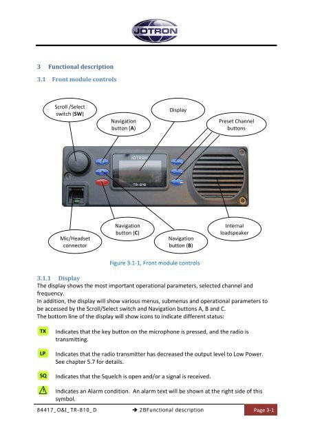
3.1 Front module controls<br />
Scroll /Select<br />
switch (SW)<br />
Navigation<br />
button (A)<br />
Display<br />
Preset Channel<br />
buttons<br />
Mic/Headset<br />
connector<br />
Navigation<br />
button (C)<br />
Navigation<br />
button (B)<br />
Internal<br />
loadspeaker<br />
Figure 3.1‐1, Front module controls<br />
3.1.1 Display<br />
The display shows the most important operational parameters, selected channel <strong>and</strong><br />
frequency.<br />
In addition, the display will show various menus, submenus <strong>and</strong> operational parameters to<br />
be accessed by the Scroll/Select switch <strong>and</strong> Navigation buttons A, B <strong>and</strong> C.<br />
The bottom line of the display will show icons to indicate different status:<br />
TX<br />
LP<br />
SQ<br />
Indicates that the key button on the microphone is pressed, <strong>and</strong> the radio is<br />
transmitting.<br />
Indicates that the radio transmitter has decreased the output level to Low Power.<br />
See chapter 5.7 for details.<br />
Indicates that the Squelch is open <strong>and</strong>/or a signal is received.<br />
!<br />
Indicates an Alarm condition. An alarm text will be shown at the right side of this<br />
symbol.<br />
84417_O&I_<strong>TR</strong>-810_D<br />
2BFunctional description<br />
Page 3‐1


