

Operators and Installation Manual TR-810.pdf - Jotron
Operators and Installation Manual TR-810.pdf - Jotron
Operators and Installation Manual TR-810.pdf - Jotron

Create successful ePaper yourself
Turn your PDF publications into a flip-book with our unique Google optimized e-Paper software.
3.1.5 Preset channel buttons<br />
These buttons are used to bring already stored channels.<br />
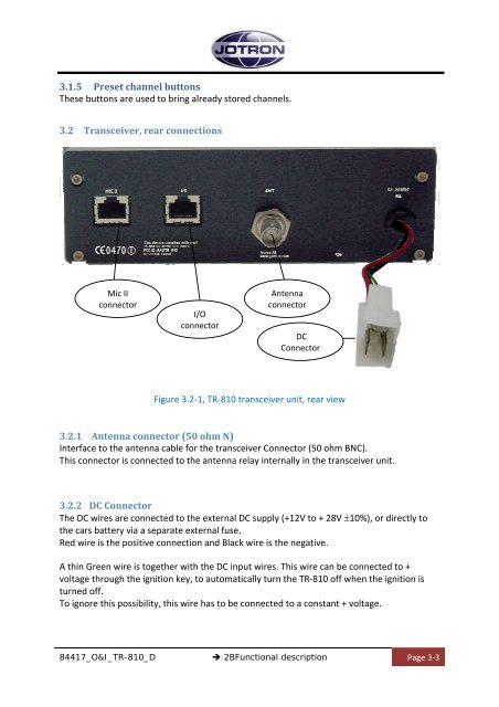
3.2 Transceiver, rear connections<br />
Mic II<br />
connector<br />
I/O<br />
connector<br />
Antenna<br />
connector<br />
DC<br />
Connector<br />
Figure 3.2‐1, <strong>TR</strong>‐810 transceiver unit, rear view<br />
3.2.1 Antenna connector (50 ohm N)<br />
Interface to the antenna cable for the transceiver Connector (50 ohm BNC).<br />
This connector is connected to the antenna relay internally in the transceiver unit.<br />
3.2.2 DC Connector<br />
The DC wires are connected to the external DC supply (+12V to + 28V ±10%), or directly to<br />
the cars battery via a separate external fuse.<br />
Red wire is the positive connection <strong>and</strong> Black wire is the negative.<br />
A thin Green wire is together with the DC input wires. This wire can be connected to +<br />
voltage through the ignition key, to automatically turn the <strong>TR</strong>‐810 off when the ignition is<br />
turned off.<br />
To ignore this possibility, this wire has to be connected to a constant + voltage.<br />
84417_O&I_<strong>TR</strong>-810_D<br />
2BFunctional description<br />
Page 3‐3


