Maintenance and Repair Manual for SAF Disc ... - Jupojos technika
Maintenance and Repair Manual for SAF Disc ... - Jupojos technika
Maintenance and Repair Manual for SAF Disc ... - Jupojos technika

Create successful ePaper yourself
Turn your PDF publications into a flip-book with our unique Google optimized e-Paper software.
<strong>Maintenance</strong> <strong>and</strong> <strong>Repair</strong> <strong>Manual</strong> <strong>for</strong> <strong>SAF</strong> <strong>Disc</strong> Brake<br />
SK RB/RLB 9019 W INTEGRAL<br />
with WABCO <strong>Disc</strong> Brake type PAN 19-1<br />
Edition 09/2005<br />
SK RB/RLB 9019 WI with WABCO PAN 19-1 11.411GB Edition 09/05 - 1 -
Vehicle <strong>and</strong> axle identification<br />
Trailer Manufacturer...........................................................................................................................................................<br />
Body type...........................................................................................................................................................................<br />
Chassis no.........................................................................................................................................................................<br />
Year of manufacturer/Trailer date in Service...................................................................................................................<br />
For the warranty procedure<br />
quote correct Axle<br />
Identification- <strong>and</strong> Serial-No.<br />
Type plate <strong>for</strong> axle identification<br />
Identification of axles in case of type plate absence<br />
Serial No. on spindle end, RH side.<br />
Example:<br />
1. Axle<br />
2. Axle<br />
3. Axle<br />
4. Axle<br />
5. Axle<br />
Ident-No.<br />
Enter axle data from <strong>SAF</strong> type plate<br />
Prod.-No. (Serial-No.)<br />
SK RB/RLB 9019 WI with WABCO PAN 19-1 11.411GB Edition 09/05 - 2 -
Contents<br />
Page<br />
Vehicle <strong>and</strong> axle identification<br />
General safety instruction<br />
Service instructions<br />
2<br />
4<br />
5<br />
Service schedule / Service chart<br />
6 - 9<br />
Spare parts / List of spare parts<br />
10 - 11<br />
Installation instructions SK RB / RLB W INTEGRAL<br />
1.0 Replace Brake Pads<br />
2.0 Replace Hub Unit SK RB INTEGRAL<br />
3.0 Replace the Brake <strong>Disc</strong> on the Hub Unit SK RB INTEGRAL<br />
12 - 14<br />
15 - 20<br />
21 - 22<br />
Installation instructions PAN 19-1 23<br />
4.0 Mechanical Sliding Calliper <strong>Disc</strong> Brake, Type PAN 19-1 (WABCO Instructions) 24 – 45<br />
General in<strong>for</strong>mation<br />
NONSTOP-SERVICE 24 46<br />
SK RB/RLB 9019 WI with WABCO PAN 19-1 11.411GB Edition 09/05 - 3 -
General safety instructions<br />
Please observe the following safety instructions in order to maintain the operational<br />
<strong>and</strong> road safety of your <strong>SAF</strong> axles <strong>and</strong> suspension systems:<br />
1. The wheel contact surfaces between the wheel disc <strong>and</strong> wheel hub <strong>and</strong> the wheel nut contact surface at the<br />
wheel disc must not be additionally painted. The contact surfaces must be clean, smooth <strong>and</strong> free from grease.<br />
Failure to observe this may result in the wheel coming loose. Any additional instructions of the wheel manufacturer<br />
must also be observed.<br />
2. Only the wheel <strong>and</strong> tyre sizes approved by the trailer builder may be used. The tyres must always have<br />
the specified inflation pressure.<br />
3. The brake systems of the tractor <strong>and</strong> the trailer/semi-trailer must be synchronised by means of a tractor/trailer<br />
brake synchronisation not later than 5,000 km after the initial start of operation of the trailer/semi-trailer in order to<br />
ensure a safe <strong>and</strong> uni<strong>for</strong>m braking behaviour <strong>and</strong> uni<strong>for</strong>m brake pad wear. Tractor/trailer brake synchronisations<br />
should be carried out by appropriately qualified <strong>and</strong> equipped brake workshops.<br />
The use of an additional braking system, such as a trailer anti-jackknife brake is <strong>for</strong>bidden by law on vehicles with<br />
type approval after January 1999.<br />
4. Be<strong>for</strong>e starting a journey, ensure that the maximum permissible axle load is not exceeded <strong>and</strong> that the load is<br />
distributed equally <strong>and</strong> uni<strong>for</strong>mly.<br />
5. On trailers with air suspension, ensure that the air bags are completely filled with air be<strong>for</strong>e starting the<br />
journey. Incompletely filled air bags may result in damage to axles, suspension, frame <strong>and</strong> superstructure <strong>and</strong><br />
impair road safety.<br />
6. Ensure that the brakes are not overheated by continuous operation.<br />
With drum brakes, overheating can result in a hazardous deterioration in the braking efficiency.<br />
With disc brakes, overheating can result in damage to surrounding components – in particular the wheel<br />
bearings. This can result in a significant deterioration in road safety, e.g. failure of wheel bearings.<br />
7. The parking brake must not be immediately applied when the brakes are hot, as the brake discs <strong>and</strong> brake drums<br />
may be damaged by different stress fields during cooling.<br />
8. Use the supports provided when loading <strong>and</strong> unloading in order to avoid damage to the axle.<br />
9. Observe the operating recommendation of the trailer builder <strong>for</strong> off-road operation of the installed axles <strong>and</strong><br />
suspension systems.<br />
The <strong>SAF</strong> definition of OFF-ROAD means driving on non-asphalted / non-concreted routes, such as e.g. gravel<br />
roads, agricultural <strong>and</strong> <strong>for</strong>estry tracks, on construction sites <strong>and</strong> in gravel pits.<br />
Off-road operation of <strong>SAF</strong> axles <strong>and</strong> suspension systems not designed <strong>for</strong> the purpose may result in damage <strong>and</strong><br />
hence to an impairment of road safety.<br />
10. <strong>SAF</strong> axles <strong>and</strong> suspension systems require continuous care, service <strong>and</strong> maintenance in order to maintain<br />
operational <strong>and</strong> road safety <strong>and</strong> to be able to recognise natural wear <strong>and</strong> defects in good time.<br />
The daily inspection of the trailer <strong>for</strong> road safety be<strong>for</strong>e starting the journey is one of the driver’s<br />
obligations.<br />
<strong>SAF</strong> recommends that at least the inspections <strong>and</strong> maintenance operations described on page 26 should<br />
be carried out.<br />
We recommend the use of original <strong>SAF</strong> spare parts.<br />
A close-knit service network of <strong>SAF</strong> partner companies is available <strong>for</strong> the technical support of the <strong>SAF</strong> axles <strong>and</strong><br />
suspension systems <strong>and</strong> <strong>for</strong> the supply of original <strong>SAF</strong> spare parts (see rear cover or on the Internet<br />
under www.saf-achsen.de).<br />
Updates will be published as necessary on the Internet under www.saf-achsen.de.<br />
SK RB/RLB 9019 WI with WABCO PAN 19-1 11.411GB Edition 09/05 - 4 -
Service instructions<br />
Safety instructions <strong>for</strong> repair work<br />
The perfect technical condition of the brake disc is of crucial importance <strong>for</strong> good driving <strong>and</strong> safe braking properties.<br />
Observe the wear limits of the brake pads <strong>and</strong> brake disc! Worn brake pads <strong>and</strong>/or brake discs can lead to a<br />
deterioration in the braking efficiency or even a complete brake failure! Danger of accidents! Burnt, glazed or oily<br />
brake pads must be replaced immediately!<br />
Brake pad replacement must always be per<strong>for</strong>med <strong>for</strong> all the wheels on an axle!<br />
During repair work on the brake system, the trailer must be st<strong>and</strong>ing on level ground <strong>and</strong> secured to prevent it from<br />
rolling away. Use only approved equipment <strong>for</strong> supporting <strong>and</strong> securing the trailer. During the repair work on the brake<br />
system, measures must be taken to ensure that the brakes are not actuated accidentally. The brakes must not be<br />
actuated as long as the brake pads are removed. Danger of injury!<br />
During repair work on the brake system, do not clean soiled areas with compressed air or other high-pressure<br />
cleaners. Danger of injury!<br />
During work on the brake system or when moving the brake calliper, hold the parts only at the outer edges to prevent<br />
fingers being trapped between brake calliper <strong>and</strong> brake bracket!<br />
During removal <strong>and</strong> installation of the brakes on the trailer, obtain assistance from a second fitter.<br />
Heavy load! Danger of injury!<br />
During repair work on the brakes away from the trailer, the brake must be gripped firmly in a suitable device, e.g. vice.<br />
High loosening <strong>and</strong> tightening torques of the bolts. Danger of injury!<br />
The brake calliper with clamping unit must not be opened.<br />
For this reason, the retaining bolts of the cover on the brake calliper must not be loosened.<br />
Carry out repair work only with recommended tools.<br />
Do not use power wrenches or other power tools!<br />
Tighten nuts <strong>and</strong> bolts only to the recommended tightening torques.<br />
When new brake pads are installed, sharp braking should be avoided <strong>for</strong> the first 50 kilometres.<br />
Long braking distances <strong>and</strong> sudden braking should also be avoided.<br />
In the event of severe damage or wear of the castings (e.g. cracks), the complete brake must be replaced.<br />
On completing repair work, a final test should be carried out on a roller dynamometer.<br />
Notes!<br />
For all working steps relating to the disc brake, please refer to the latest edition of the installation <strong>and</strong> maintenance<br />
instructions <strong>for</strong> the respective WABCO disc brake.<br />
SK RB/RLB 9019 WI with WABCO PAN 19-1 11.411GB Edition 09/05 - 5 -
Service schedule<br />
Service schedule<br />
Periodic check<br />
Whichever occurs first<br />
Mileage intervals ><br />
Time intervals ><br />
After first<br />
5,000 km or<br />
after first<br />
month<br />
every<br />
30,000 km<br />
every<br />
3 months<br />
every<br />
75,000 km<br />
every<br />
6 months<br />
every<br />
150,000 km<br />
every<br />
12 months<br />
Mechanical check<br />
Attention: Torque check wheel nuts after the first 50 km<br />
<strong>and</strong> 150 km to recommended torque setting, also after any<br />
removal of the wheel.<br />
Visual <strong>and</strong> safety inspection<br />
Hub Unit maintenance free.<br />
Visual inspection <strong>for</strong> grease leaks.<br />
Inspect the brake calliper guide system.<br />
Check <strong>for</strong> free movement <strong>and</strong> sliding action.<br />
Check rubber dust covers <strong>for</strong> cracks <strong>and</strong> damages.<br />
Check adjuster cap <strong>for</strong> correct seating.<br />
<br />
<br />
<br />
Inspect the brake pas thickness<br />
at regular intervals (e.g. when ever tyre pressure is<br />
checked) but at least every 3 months.<br />
<br />
Inspect the brake disc <strong>for</strong> cracks.<br />
- Per<strong>for</strong>m general annual inspection<br />
(brakes, air bags, tyres, etc.)<br />
- Per<strong>for</strong>m general annual safety check<br />
(tractor/trailer brake compatibility, LSV etc.)<br />
Special service conditions<br />
Vehicles with long st<strong>and</strong>ing periods:<br />
<br />
Service at specified time intervals.<br />
<br />
<br />
<br />
Vehicles used under extreme conditions:<br />
e.g. construction site operation, multi-shift operation<br />
Shorten the service interval to 6 months / 75,000 km<br />
Warranty claims will only be accepted as long as the operating <strong>and</strong> maintenance instructions have been<br />
complied with <strong>and</strong> if <strong>SAF</strong> approved spare parts have been fitted.<br />
NOTE!<br />
If the sealmark on the hub nut is broken be<strong>for</strong>e the end of the 1,000,000 km this will invalidate all warranty<br />
coverage unless the repair works have been carried out in an <strong>SAF</strong>-authorised workshop.<br />
SK RB/RLB 9019 WI with WABCO PAN 19-1 11.411GB Edition 09/05 - 6 -
Service chart<br />
Hub Unit maintenance free<br />
Check hub unit at each brake disc replacement <strong>for</strong> wear <strong>and</strong> grease leackage.<br />
When brake pads replacing check the rubber boot seals of the brake calliper.<br />
Never use high-pressure cleaners or cleaning fluids on the brake disc or hub<br />
unit. Clean stub axle of any contamination <strong>and</strong> apply fresh <strong>SAF</strong> fitting paste.<br />
Lubricant specifications:<br />
Grease <strong>for</strong> lubrication is contained<br />
in every repair kit.<br />
Stub axle:<br />
<strong>SAF</strong> fitting paste<br />
<strong>SAF</strong> Part No. 5 387 0015 06<br />
Tightening the hub nut<br />
On LH side – LH thread<br />
On RH side – RH thread<br />
Tightening torque 900 Nm. Each hub unit must be<br />
rotated smoothly at least twice while tightening the<br />
bolts.<br />
Hub nuts with LH thread are marked:<br />
Groove on the bound.<br />
Admissible axial backlash (wheel bearing play)<br />
at hub unit: 0 – 0.20 mm<br />
Tightening torque, see table<br />
NOTE! Failure to observe these instructions may result in an road accident risk! Worn brake linings or excessively<br />
worn brake discs result in a reduction of the braking efficiency or in a complete failure of the brake.<br />
Wear limits<br />
C<br />
A<br />
B<br />
E<br />
Brake <strong>Disc</strong><br />
Brake Pads<br />
Diameter<br />
(mm)<br />
“A“<br />
new (mm)<br />
“B”<br />
Wear limit (mm)<br />
“C”<br />
new (mm)<br />
“E”<br />
Wear limit (mm)<br />
377 45 37.0 30 11.0<br />
Brake pads, always fitt only brake pads material grade approved by <strong>SAF</strong>. Under normal wear <strong>and</strong> replacement<br />
conditions always renew the brake pads kit on both sides of the axle. Difference in brake pad wear max. 5.0 mm<br />
(inboard / outboard pad)<br />
Tightening torques (Nm) Tighten the bolts using a torque wrench.<br />
NOTE! The assembly bolts item 45, 56, 56.1 must be replaced when carrying out repair works.<br />
The bolts must not be oiled or greased when assembling.<br />
Tighten the assembly bolts with a calibrated torque wrench.<br />
Assembly Item SK RB 9019 W INTEGRAL<br />
Axle nut 21 / 22 Tightening torque 900 Nm. Each hub unit must be rotated<br />
smoothly at least twice while tightening the bolts.<br />
INTEGRAL – Brake disc<br />
Double hex. Bolt, socket 13, M12x1.5<br />
45 1. pre-tighten diagonally with 20 Nm<br />
2. further tighten diagonally with torque angle 90°<br />
(in-service inspection torque 130 Nm)<br />
Brake calliper on axle<br />
Hexagon bolt M16x1.5<br />
Brake chamber hex. nut M16x1.5<br />
56<br />
56.1<br />
290 Nm<br />
Tighten alternately <strong>and</strong> uni<strong>for</strong>mly in 2 stages.<br />
1. Pre-tightening 120 Nm<br />
2. Torque angle 210 Nm<br />
(in-service inspection torque 210 Nm)<br />
Pad retainer clamp 63 45 Nm<br />
Assembly tools <strong>SAF</strong> Part No. Assembly tools <strong>SAF</strong> Part No.<br />
Hub nut socket 4 434 3828 00 Tool box WABCO 3 434 6010 00<br />
Puller <strong>for</strong> Hub Unit 4 434 3822 00<br />
SK RB/RLB 9019 WI with WABCO PAN 19-1 11.411GB Edition 09/05 - 7 -
Service schedule<br />
Fault-finding procedure<br />
<strong>Disc</strong> brake<br />
Lift vehicle,<br />
turn wheel<br />
by h<strong>and</strong><br />
Does wheel<br />
turn freely?<br />
NO<br />
YES<br />
Residual pressure<br />
in brake cylinder?<br />
Running<br />
clearence OK?<br />
NO<br />
YES<br />
NO<br />
YES<br />
Running<br />
clearence OK?<br />
NO<br />
YES<br />
Check upline<br />
brake devices<br />
<strong>and</strong> replace,<br />
if necessary<br />
END<br />
Check adjuster<br />
END<br />
Uneven brake<br />
pad wear? 1)<br />
NO<br />
END<br />
YES<br />
Adjuster OK?<br />
NO<br />
YES<br />
Check brake<br />
caliper bearings<br />
<strong>and</strong> repair,<br />
if necessary<br />
END<br />
Brake caliper<br />
guide<br />
system OK?<br />
NO<br />
YES<br />
Replace<br />
brake<br />
caliper<br />
END<br />
Binding not<br />
due to<br />
disc brake<br />
END<br />
Check brake<br />
caliper bearings<br />
<strong>and</strong> repair,<br />
if necessary<br />
END<br />
1) Difference between wear of inboard <strong>and</strong> outboard pad, <strong>and</strong> diagonal wear see diagram.<br />
SK RB/RLB 9019 WI with WABCO PAN 19-1 11.411GB Edition 09/05 - 8 -
Service schedule<br />
Check brakes <strong>for</strong> wear<br />
Wear limit<br />
Wear on the middle of the lining can be measured with a tape measure or a<br />
ruler either at the shoulder bolt (long bolt near the disc run in) or at the play<br />
bolt (short bolt near the disc run in). Here, the distance between the axle<br />
flange <strong>and</strong> the edge of the housing of each bolt is measured (see illustration).<br />
The amount of wear is determined to have been reached or exceeded by the<br />
following criteria:<br />
PAN 19-1<br />
Long guide pin > 94 mm<br />
Short guide pin > 67 mm<br />
Brake Pad<br />
Note!<br />
Observe the wear limits of the brake pads.<br />
C<br />
A<br />
B<br />
Check the thickness of the brake pads <strong>for</strong> compliance with the legal<br />
requirements at regular intervals, but at least every three months, depending<br />
on the operation of the vehicle.<br />
E = Wear limits, see diagram<br />
C = New brake pad, see diagram<br />
E<br />
Brake <strong>Disc</strong><br />
Inspect the braking surface of the brake disc carefully <strong>for</strong> serviceability.<br />
A 1 -Network-like cracks are permissible.<br />
B 1 -Cracks up to max. 1.5 mm (width <strong>and</strong> depth) running towards the<br />
middle of the hub are permissible<br />
C 1 -Unevenness in the disc surface is permissible.<br />
D 1 -Cracks going right through the disc are not permissible.<br />
Check the brake disc thickness <strong>and</strong> turn down, if necessary.<br />
For safety reasons, the minimum thickness <strong>for</strong> turning down the brake<br />
discs is 39 – 40 mm.<br />
SK RB/RLB 9019 WI with WABCO PAN 19-1 11.411GB Edition 09/05 - 9 -
Spare parts<br />
Torque wrench settings<br />
Anziehdrehmomente<br />
Tighten the assembly bolts with a calibrated torque<br />
Die wrench. Schraubverbindungen mit Drehmomentschlüssel anziehen.<br />
Radmuttern:<br />
Wheel nuts:<br />
Mittenzentrierung M22x1,5 600 Nm<br />
Hinweise Hub-spigot der centred Räderhersteller fixing M22x1.5 beachten/ 600 Nm<br />
Refer to wheel manufacturers recommendations!<br />
64<br />
64.2 64.1<br />
064<br />
63<br />
63.1 63.2<br />
059 / 060<br />
070<br />
80<br />
70.3<br />
70.1<br />
66<br />
83<br />
70.6<br />
65<br />
80.3<br />
80<br />
80.1<br />
80.2<br />
56<br />
83<br />
080<br />
61 / 62<br />
01<br />
56.1<br />
Driving<br />
Fahrtrichtung<br />
direction<br />
Links-<br />
LH<br />
Rechtsgewinde<br />
/ RG thread<br />
22 / 22.1<br />
INTEGRAL Brake <strong>Disc</strong><br />
INTEGRAL Bremsscheibe<br />
NOTE! Achtung!<br />
Item Pos. 39.1, 39.1, 45, 45, 56 56 <strong>and</strong> u. 56.1 56.1: müssen<br />
The bei Reparaturarbeiten assembly bolts must erneuert be replaced werden.<br />
when carrying out repair works.<br />
78.1<br />
78<br />
030<br />
31<br />
39.1<br />
29<br />
34<br />
45<br />
40<br />
27<br />
INTEGRAL Radnabeneinheit<br />
Achtung!!!! Übersetzung fehlt<br />
IPL_17_420_S<br />
SK RB/RLB 9019 WI with WABCO PAN 19-1 11.411GB Edition 09/05 - 10 -
List of spare parts<br />
Item Parts designation Item Parts designation<br />
01 Axle beam assembly 059 Brake calliper assembly, RH<br />
including items 62, 64, 65, 66, 070, 080<br />
22 Axle nut, RH, W.A.F. 85<br />
22.1 Axle nut, LH, W.A.F. 85 61/62 Brake calliper carrier, not available<br />
27 INTEGRAL wheel hub 63 Pad retaining clamp<br />
incl. Kerola <strong>and</strong> exciter ring including items 63.1, 63.2<br />
29 INTEGRAL Brake <strong>Disc</strong> 64 Brake pads<br />
including items 64.1, 64.2<br />
030 Wheel bolt kit 65 Adjuster plug<br />
including items 31, 34 66 Air bag protective cap<br />
31 Wheel bolt<br />
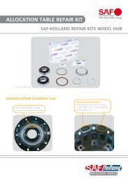
34 Wheel nut 070 <strong>Repair</strong> kit<br />
Guide pin<br />
39.1 O-ring including items 70.1 – 70.6, 80, 83<br />
40 Hub cap with O-ring<br />
78 ABS rod sensor<br />
45 Double hex. bolt M12x1.5 SW 13 78.1 Rod sensor clamping bush<br />
56 Hexagon head bolt 080 <strong>Repair</strong> kit<br />
56.1 Shoulder bolt Guide pin<br />
including items 80, 80.1 – 80.3, 83<br />
059 Brake calliper assembly, LH<br />
including items 61, 64, 65, 66, 070, 080<br />
NOTE!<br />
Item 39.1, 45, 56 , 56.1<br />
The assembly bolts must be replaced when carrying out repair works.<br />
All repair kits available only as complete sets!<br />
When ordering spare parts quote correct axle identification serial no., refer to the axle type plate.<br />
SK RB/RLB 9019 WI with WABCO PAN 19-1 11.411GB Edition 09/05 - 11 -
Installation instructions<br />
1.0 Replace Brake Pads<br />
1.1 Fill the air system to cut-off pressure <strong>and</strong> release the parking brake.<br />
1.2 <strong>Disc</strong>onnect the plug from the wear indicator <strong>and</strong> pull the ABS sensor<br />
out of the sensor holder, if installed.<br />
1.3 Loosen <strong>and</strong> remove the retaining screw of the pad retainer bracket.<br />
1.4 Pull the pad retainer bracket out of the brake calliper.<br />
1.5 Lever out the plug of the adjuster using a screwdriver.<br />
Notes:<br />
– Use a suitable screwdriver.<br />
– Insert the screwdriver between plug <strong>and</strong> seal ring.<br />
– Do not rest the screwdriver on the housing seal ring <strong>and</strong> apply<br />
pressure here to remove the plug.<br />
– The seal ring must not be de<strong>for</strong>med or damaged.<br />
1.6 Back off the brake at the hexagon of the adjuster with a ring spanner,<br />
then loosen again by approx. 1/4 spanner rotation.<br />
Notes:<br />
The direction of rotation <strong>for</strong> backing off the adjuster is to the right, i.e. in<br />
clockwise direction.<br />
Caution:<br />
During backing off, the pressure plate must be pushed back by h<strong>and</strong> at the<br />
same time so that the pin serving as twist lock <strong>for</strong> the adjusting pin does not<br />
slip out of the retaining groove. Otherwise there is a risk of the adjusting pin<br />
also turning <strong>and</strong> destroying the protective cap!<br />
1.7 Push the brake calliper to the rim side <strong>and</strong> take out the brake pad.<br />
1.8 Push the brake calliper inwards <strong>and</strong> remove the brake pad together<br />
with the pressure plate (WABCO).<br />
SK RB/RLB 9019 WI with WABCO PAN 19-1 11.411GB Edition 09/05 - 12 -
Installation instructions<br />
Check brake calliper <strong>for</strong> proper function <strong>and</strong> serviceability of the parts by<br />
– Checking the axial shiftability <strong>and</strong> sliding function<br />
– Checking the admissible wear clearance of the guide pins<br />
– Checking the automatic adjustment function<br />
– Checking the air bag protection caps <strong>and</strong> seals<br />
If necessary, replace defective parts or brake callipers (see section 4.0).<br />
1.9 Move the brake callipers by h<strong>and</strong> along the guide pins over their full<br />
travel <strong>and</strong> check <strong>for</strong> ease of movement.<br />
1.10 If the brake callipers bind, replace the guide pins.<br />
1.11 Check air bag protection cap (A).<br />
Caution:<br />
If air bag protection cap (A) is defective, check whether any dirt or water has<br />
entered the brake <strong>and</strong> damaged the internal parts of the brake or the seal seat<br />
in the brake calliper due to corrosion. If in doubt, replace the brake calliper.<br />
Check air bag protection cap (B).<br />
If damage is discovered, replace the corresponding protection caps (see<br />
section 4.0)<br />
B<br />
A<br />
B<br />
1.12 Clean the contact surface of the brake pads.<br />
1.13 Push the brake calliper inwards <strong>and</strong> install pressure plate (WABCO)<br />
<strong>and</strong> new brake pad.<br />
1.14 Push the brake calliper to the rim side <strong>and</strong> install a new brake pad.<br />
1.15 Install the hold-down springs over brake pads <strong>and</strong> pressure plate.<br />
1.16 Push brake pad retainer bracket into the brake calliper.<br />
SK RB/RLB 9019 WI with WABCO PAN 19-1 11.411GB Edition 09/05 - 13 -
Installation instructions<br />
1.17 Insert the retaining screw of the brake pad retainer bracket <strong>and</strong> tighten<br />
to the prescribed torque.<br />
Torque wrench settings see page 7<br />
Adjust clearance<br />
1.18 Fill the air system to cut-off pressure <strong>and</strong> release the parking brake.<br />
1.19 Lever out the plug of the adjuster using a screwdriver.<br />
Notes:<br />
– Use a suitable screwdriver.<br />
– Insert the screwdriver between plug <strong>and</strong> seal ring.<br />
– Do not rest the screwdriver on the housing seal ring <strong>and</strong> apply<br />
pressure here to remove the plug.<br />
The seal ring must not be de<strong>for</strong>med or damaged.<br />
1.20 Adjust the clearance by:<br />
- Filling the air system to cut-off pressure <strong>and</strong> releasing the parking<br />
brake.<br />
- Adjust the clearance using the adjuster.<br />
1.21 Install the plug <strong>for</strong> the adjuster again correctly.<br />
Caution!<br />
If the plug is lost, water can enter the system <strong>and</strong> cause corrosion to the<br />
adjuster.<br />
Caution!<br />
After replacing the brake pads, check the proper function of the brakes<br />
on a roller dynamometer.<br />
SK RB/RLB 9019 WI with WABCO PAN 19-1 11.411GB Edition 09/05 - 14 -
Installation instructions<br />
2.0 Replace Hub Unit SK RB INTEGRAL<br />
2.1 Loosen <strong>and</strong> remove the mounting nuts <strong>for</strong> the brake cylinder.<br />
2.2 Remove the brake cylinder from the brake calliper <strong>and</strong> place to one<br />
side.<br />
2.3 Loosen <strong>and</strong> remove the retaining screws <strong>for</strong> the brake calliper.<br />
2.4 Remove the brake calliper from the brake carrier <strong>and</strong> place to one<br />
side.<br />
2.5 Pull the wheel cap off the hub unit.<br />
2.6 Loosen the axle nut <strong>and</strong> pull off the stub axle.<br />
Notes: On LH side as seen in direction of travel – LH thread<br />
SK RB/RLB 9019 WI with WABCO PAN 19-1 11.411GB Edition 09/05 - 15 -
Installation instructions<br />
Axle nut wrench<br />
W.A.F. 85 (<strong>SAF</strong> Part No. 4 434 3828 00)<br />
2.7 Pull the complete hub unit SK RB INTEGRAL with brake disc off the<br />
stub axle <strong>and</strong> place to one side.<br />
2.8 If necessary, use a puller to pull the hub unit SK RB INTEGRAL off the<br />
stub axle.<br />
2.9 Clean the seating surfaces <strong>for</strong> the hub unit SK RB INTEGRAL on the<br />
stub axle <strong>and</strong> coat all over with a minimum amount of <strong>SAF</strong> mounting<br />
paste.<br />
<strong>SAF</strong> fitting paste<br />
(<strong>SAF</strong> Part No. 5 387 0015 06)<br />
SK RB/RLB 9019 WI with WABCO PAN 19-1 11.411GB Edition 09/05 - 16 -
Installation instructions<br />
2.10 Prepare the replacement hub unit SK RB INTEGRAL.<br />
2.11 Insert a new O-ring (39.1) into the O-ring groove of the hub unit.<br />
Pos. 39.1<br />
2.12 Push the hub unit SK RB INTEGRAL onto the stub axle.<br />
2.13 Screw on the axle nut.<br />
Notes: On LH side as seen in direction of travel – LH thread<br />
SK RB/RLB 9019 WI with WABCO PAN 19-1 11.411GB Edition 09/05 - 17 -
Installation instructions<br />
2.14 Tighten the axle nut to the prescribed torque, at the same time turning<br />
the hub unit through one revolution.<br />
Torque wrench settings see page 7<br />
Notes: On LH side as seen in direction of travel – LH thread<br />
Axle nut wrench<br />
W.A.F. 85 (<strong>SAF</strong> Part No. 4 434 3828 00)<br />
2.15 Install new wheel cap with O-ring in the hub unit SK RB INTEGRAL.<br />
Pos. 40<br />
2.16 Position the brake calliper on the brake carrier <strong>and</strong> secure in this<br />
position using new retaining screws <strong>for</strong> the brake calliper.<br />
Pos. 56.1<br />
Caution!<br />
The fitting pin (Pos. 56.1) must only be inserted into the tapped bore with<br />
the recess in the brake calliper.<br />
Pos. 56<br />
SK RB/RLB 9019 WI with WABCO PAN 19-1 11.411GB Edition 09/05 - 18 -
Installation instructions<br />
2.17 Tighten retaining screws (Pos. 56 <strong>and</strong> 56.1) to the prescribed torque.<br />
Caution!<br />
Use only new hex. head bolts / fitting pins! (Pos. 56 <strong>and</strong> 56.1)<br />
Pos. 56.1<br />
The bolts must not be oiled or greased!<br />
Torque wrench settings see page 7<br />
Pos. 56<br />
2.18 Check brake calliper <strong>for</strong> proper function <strong>and</strong> serviceability of the<br />
parts, see section 1.<br />
2.19 Check the condition of the gasket (A) at the brake cylinder flange <strong>and</strong><br />
replace the gasket, if necessary.<br />
B<br />
Use new lock nuts (B).<br />
A<br />
2.20 Clean sealing surface (A) on the brake calliper.<br />
A<br />
SK RB/RLB 9019 WI with WABCO PAN 19-1 11.411GB Edition 09/05 - 19 -
Installation instructions<br />
2.21 Bolt the brake cylinder to the brake calliper, tightening the lock nuts<br />
uni<strong>for</strong>mly <strong>and</strong> alternately in two steps using the prescribed method.<br />
Torque wrench settings see page 7<br />
2.22 Adjust the clearance, see chapter 1<br />
2.23 Install the plug <strong>for</strong> the adjuster again correctly.<br />
Caution!<br />
If the plug is lost, water can enter the system <strong>and</strong> cause corrosion to the<br />
adjuster.<br />
2.24 Install the ABS sensor in the sensor holder <strong>and</strong> press against the<br />
exciter ring.<br />
Caution!<br />
After replacing the hub unit SK RB INTEGRAL, check the proper function of the brakes on a roller<br />
dynamometer.<br />
SK RB/RLB 9019 WI with WABCO PAN 19-1 11.411GB Edition 09/05 - 20 -
Installation instructions<br />
3.0 Replace the Brake <strong>Disc</strong> on the Hub Unit SK RB INTEGRAL<br />
3.1 Remove <strong>and</strong> install brake pads from brake calliper.<br />
3.2 Remove <strong>and</strong> install brake cylinder from brake calliper.<br />
3.3 Remove <strong>and</strong> install brake calliper from brake carrier.<br />
3.4 Remove <strong>and</strong> install wheel cap.<br />
3.5 Remove <strong>and</strong> install axle nut.<br />
3.6 Pull hub unit SK RB INTEGRAL complete with brake<br />
disc from the stub axle <strong>and</strong> place to one side.<br />
See installation instructions, chapter 1<br />
See installation instructions, chapter 2<br />
3.7 Loosen <strong>and</strong> remove the DSK bolts holding the brake disc.<br />
Torque wrench settings see page 7<br />
3.8 Remove the brake disc from hub unit SK RB INTEGRAL.<br />
3.9 Clean the contact surfaces <strong>for</strong> the brake disc on the hub unit SK RB<br />
INTEGRAL.<br />
Blow out the tapped bores <strong>for</strong> the DSK bolts with compressed air.<br />
Check the thread <strong>for</strong> easy bolt insertion.<br />
SK RB/RLB 9019 WI with WABCO PAN 19-1 11.411GB Edition 09/05 - 21 -
Installation instructions<br />
3.10 Place the new brake disc on the hub unit SK RB INTEGRAL <strong>and</strong> align.<br />
3.11 Screw in new DSK bolts to secure the brake disc <strong>and</strong> tighten using the<br />
prescribed tightening method.<br />
Caution!<br />
Use only new DSK bolts!!<br />
DSK bolts must not be oiled or greased!<br />
3.12 Insert a new O-ring (39.1) into the O-ring groove of the hub unit.<br />
Pos. 39.1<br />
3.13 Install hub unit SK RB INTEGRAL complete with<br />
brake disc on the stub axle.<br />
See installation instructions, chapter 2<br />
Caution!<br />
After replacing the brake disc on the hub unit SK RB INTEGRAL, check the proper function of the<br />
brakes on a roller dynamometer.<br />
SK RB/RLB 9019 WI with WABCO PAN 19-1 11.411GB Edition 09/05 - 22 -
Installation instructions – PAN 19-1<br />
4. Mechanical Sliding Calliper <strong>Disc</strong> Brake Type PAN 19-1<br />
Installation <strong>and</strong> Service Instructions<br />
SK RB/RLB 9019 WI with WABCO PAN 19-1 11.411GB Edition 09/05 - 23 -
Installation Instructions – PAN 19-1<br />
4.0 Dismantling <strong>and</strong> Assembling WABCO Brake Callipers<br />
Installation <strong>and</strong> Service Instructions PAN 19-1<br />
4. 1 Description of the Mechanical Sliding Calliper <strong>Disc</strong> Brake<br />
4. 1.1 Introduction<br />
The brake “PAN 19-1 ” is a newly developed pneumatic single-cylinder brake designed <strong>for</strong> use on the<br />
front <strong>and</strong> rear axles of commercial vehicles <strong>and</strong> trailers with 19.5” or 22.5” wheel rims as service brake,<br />
emergency brake <strong>and</strong> parking brake. It is actuated mechanically via a diaphragm cylinder or spring brake<br />
actuator cylinder that is connected directly to a cover of the brake calliper.<br />
The direct connection of the brake cylinder to the brake calliper permits a short overall axial length of the brake.<br />
This results in optimum utilisation of the installation space available.<br />
The complete disc brake, including brake cylinder, consists of two sub-assemblies:<br />
Brake calliper group 59/60<br />
Brake carrier 61/62<br />
Fig. 1<br />
The brake calliper 59, 60 slides axially on guide pins (70.1, 80.2) of the brake carrier 61, 62.<br />
The brakes pads (64.1) are guided <strong>and</strong> supported in the brake carrier <strong>and</strong> can slide axially.<br />
The brake pads are held by a pad retaining bracket (63.1) <strong>and</strong> spring clips (64.2) - see Figures 1 to 3.<br />
The radially open design of the brake calliper permits a quick <strong>and</strong> easy pad change.<br />
In order to prolong the pad changing intervals with this brake system, brake pads with a large wear volume are<br />
employed.<br />
In order to compensate pad wear, the brake actuator is equipped with a <strong>for</strong>ce-dependent, infinitely variable<br />
automatic adjuster. This maintains a constant preset clearance, irrespective of the load collective or different<br />
operating conditions. This, together with the sturdy <strong>and</strong> rigid design of the brake calliper, ensures reliable<br />
control of the pedal travels <strong>and</strong> increases the travel reserve <strong>for</strong> emergency braking.<br />
All rubber parts of the brake <strong>and</strong> the grease fillings are maintenance-free, as long as they suffer no mechanical<br />
damage.<br />
The disc brake can be optionally equipped with an electric wear indicator (64.3).<br />
SK RB/RLB 9019 WI with WABCO PAN 19-1 11.411GB Edition 09/05 - 24 -
Installation Instructions – PAN 19-1<br />
Arrow,<br />
direction of rotation<br />
<strong>for</strong> <strong>for</strong>ward travel<br />
Figure 2 Top view<br />
Figure 3 Side view<br />
SK RB/RLB 9019 WI with WABCO PAN 19-1 11.411GB Edition 09/05 - 25 -
Installation Instructions – PAN 19-1<br />
These instructions together with the following figures describe the steps <strong>and</strong> work processes necessary <strong>for</strong> replacement<br />
of the available repair kits. The wrench sizes <strong>and</strong> tightening torques mentioned in the work processes can be found in<br />
the corresponding items of Table 1. The grease from the tube supplied in the repair kits should be used <strong>for</strong> greasing.<br />
Safety Instructions <strong>for</strong> <strong>Repair</strong> Work<br />
The perfect technical condition of the disc brake is crucial <strong>for</strong> good operating <strong>and</strong> safe braking characteristics.<br />
Observe the wear limits of the brake pads <strong>and</strong> brake disc. Worn brake pads <strong>and</strong> brake discs result in reduced braking<br />
efficiency or even failure of the brakes! Accident risk! Burned, glazed or oily brake pads must be replaced immediately.<br />
Always replace all the brake pads on the same axle at the same time!<br />
During repair work on the brakes, the trailer must be parked on level ground <strong>and</strong> secured to prevent it rolling away.<br />
Use only approved equipment <strong>for</strong> jacking up <strong>and</strong> supporting the trailer.<br />
During repair work on the brakes, take measures to ensure that the brake is not accidentally actuated.<br />
The brake must not be actuated when the pads are removed! Risk of injury!<br />
During repair work on the brakes, do not clean soiled areas with compressed air or other high-pressure cleaners! Risk of<br />
injury!<br />
When working on the brakes or when shifting the brake calliper, hold with your h<strong>and</strong>s only on the outside in order to<br />
avoid crushing of the fingers between brake calliper <strong>and</strong> brake carrier!<br />
During removal <strong>and</strong> installation on the brake on the vehicle, always have a second fitter to help.<br />
Heavy load! Risk of injury!<br />
During repair work on the brakes off the vehicle, the brake must be securely clamped in a suitable device, e.g. a vice,<br />
due to the large loosening <strong>and</strong> tightening torques. Risk of injury!<br />
The brake calliper with the closing unit must not be opened. The retaining screws on the cover of the brake calliper must<br />
there<strong>for</strong>e not be loosened.<br />
Only WABCO original spare parts <strong>and</strong> only approved brake pads may be used.<br />
Carry out repair work only using the recommended tools. Do not use power wrenches or other power tools. Tighten nuts<br />
<strong>and</strong> bolts only to the prescribed torques.<br />
When new brake pads are fitted, do not brake sharply <strong>for</strong> the first 50 km. Prolonged periods of braking <strong>and</strong> abrupt<br />
braking should also be avoided.<br />
In the event of severe damage to or wear of the castings (e.g. cracks), the complete brake must be replaced as<br />
described in these instructions.<br />
On completion of repair work, a final test must be carried out on a roller dynamometer.<br />
If a roller dynamometer is not available, carry out a trial run with braking tests.<br />
SK RB/RLB 9019 WI with WABCO PAN 19-1 11.411GB Edition 09/05 - 26 -
Installation Instructions – PAN 19-1<br />
4.2 Check the Brake<br />
Caution: Do not use power wrenches! When working on the brakes or when<br />
shifting the brake calliper, hold with your h<strong>and</strong>s only on the outside in order to<br />
avoid crushing of the fingers between brake calliper <strong>and</strong> brake carrier!<br />
4.2.1 Check Adjuster<br />
General Note: The turning directions <strong>and</strong> torques at the hexagon of<br />
the adjuster are indicated in Table 1, position I.<br />
Remove plug 65 <strong>for</strong> adjuster 65.1.<br />
Using a ring spanner (Table 1, position I) on the hexagon of adjuster<br />
65.1, turn the adjuster approx. 1/2 a rotation in clockwise direction.<br />
Caution: Do not overload the hexagon of the adjuster 65.1! Do not use an<br />
open-jaw wrench <strong>for</strong> the adjuster. The space <strong>for</strong> the ring spanner on the<br />
hexagon must be large enough to allow it to turn without being hindered<br />
during rotation!<br />
Apply the brakes approx. 5 times (approx. 1 bar). If the adjuster is<br />
functioning correctly, the ring spanner (arrow) should turn back slowly<br />
in anti-clockwise direction.<br />
65<br />
65.1<br />
Fig. 4<br />
Note: With increasing adjustment, the turn angle or movement of the ring<br />
spanner will become smaller.<br />
If the ring spanner turns back as described, the adjuster is OK.<br />
Remove the ring spanner.<br />
Insert plug 65 again, ensuring that it seals tightly.<br />
Possible problems:<br />
The adjuster 65.1 or ring spanner (arrow) turns:<br />
a) Not at all<br />
b) Only the first time the brakes are applied<br />
c) Forward <strong>and</strong> back again at each application of the brakes then the<br />
adjuster is not OK.<br />
In this case, replace the brake as described in section 4.<br />
65.1<br />
65<br />
Bild 5<br />
SK RB/RLB 9019 WI with WABCO PAN 19-1 11.411GB Edition 09/05 - 27 -
Installation Instructions – PAN 19-1<br />
4.3 Check Brake Pads<br />
Note: Check the brake pad thickness at regular intervals <strong>and</strong> depending on<br />
the vehicle operation, during service intervals <strong>and</strong> in accordance with the<br />
statutory provisions. Burned, glazed or oily brake pads must be replaced<br />
immediately.<br />
Always replace all the brake pads on the same axle at the same<br />
time!<br />
Caution: In order to avoid damage to the brake disc, the brake pads must<br />
be replaced at the latest when a brake pad thickness of 2 mm over the<br />
brake pad carrier plate is measured at the thinnest point.<br />
Pad carrier<br />
Brake pad<br />
The remaining pad thickness must not be less than 2 mm.<br />
A = Remaining pad thickness 2 mm.<br />
B = Total pad thickness 21 mm.<br />
When the remaining pad thickness A < 2 mm, replace the brake pads<br />
as described in section 4.5.<br />
Fig. 6<br />
Wear Measurement<br />
The mean brake pad wear can be checked using a rollmeter or ruler,<br />
depending on the accessibility, either at the fitting pin (long pin at the<br />
leading end of the pad) or at the clearance pin (short pin at the trailing<br />
end of the pad).<br />
Measure the distance between the axle flange <strong>and</strong> the edge of the<br />
brake calliper of the respective guide pin (arrows).<br />
The wear limit is reached or exceeded at the following values:<br />
Short guide pin: Wear limit > 67 mm<br />
Replace brake pads<br />
Long guide pin: Wear limit > 94 mm<br />
Replace brake pads<br />
4.4 Check Brake <strong>Disc</strong><br />
Remove the brake pads as described in section 4.5 <strong>and</strong> measure the<br />
brake disc thickness in the brake pad contact area.<br />
C = Total thickness of new brake disc 45 mm<br />
D = Wear limit 37 mm, the brake disc must be replaced.<br />
Replacement of both discs on the axle is recommended.<br />
E = Total thickness of new brake pad 30 mm<br />
F = Brake pad carrier plate 9 mm<br />
G = Minimum thickness of brake pad 2 mm<br />
H = Absolute minimum thickness of brake pad <strong>and</strong> pad carrier<br />
plate 11 mm, the brake pads must be replaced.<br />
Caution: Observe the wear limits of the brake pads <strong>and</strong> brake discs!<br />
Worn brake pads <strong>and</strong> brake discs reduce the braking efficiency <strong>and</strong><br />
can even lead to failure of the brakes!<br />
Risk of accidents!<br />
Fig. 7<br />
Fig. 8<br />
SK RB/RLB 9019 WI with WABCO PAN 19-1 11.411GB Edition 09/05 - 28 -
Installation Instructions – PAN 19-1<br />
4.5 Brake Pad Replacement<br />
Caution: Do not use power wrenches! When working on the brakes or<br />
when shifting the brake calliper, hold with your h<strong>and</strong>s only on the<br />
outside in order to avoid crushing of the fingers between brake calliper<br />
<strong>and</strong> brake carrier!<br />
<strong>Disc</strong>onnect the plug from the wear indicator 64.3 (arrow).<br />
Loosen screw 63.2 of pad holder bracket 63.1 using a spanner<br />
(Table 1, position II) <strong>and</strong> remove the screw.<br />
63.1<br />
64.3<br />
Pull pad holder bracket 63.1 out of the brake calliper.<br />
63.2<br />
Fig. 9<br />
Remove three spring clips 64.2 from brake pads 64.1 <strong>and</strong> pressure<br />
plate 64.5.<br />
Remove wear indicator 64.3 with sensors from the brake pads.<br />
Remove both cable clips 64.4 from the brake calliper.<br />
64.3<br />
64.4<br />
Fig. 10<br />
64.5<br />
64.1<br />
64.2<br />
64 1<br />
Remove plug 65 <strong>for</strong> adjuster 65.1 from brake calliper.<br />
Turn back the brake at the hexagon of the adjuster 65.1 using a ring<br />
spanner, then loosen again by approx. 1/4 rotation.<br />
Fig. 11<br />
Note: The adjuster is turned back by turning the spanner to the right, i.e. in<br />
clockwise direction.<br />
Caution: During backing off, the pressure plate 64.5 must be pushed<br />
back by h<strong>and</strong> at the same time so that the pin serving as twist lock <strong>for</strong><br />
the adjusting pin does not slip out of the retaining groove. Otherwise<br />
there is a risk of the adjusting pin also turning <strong>and</strong> destroying the<br />
protective cap!<br />
65<br />
65.1<br />
Fig. 12<br />
SK RB/RLB 9019 WI with WABCO PAN 19-1 11.411GB Edition 09/05 - 29 -
Installation Instructions – PAN 19-1<br />
Push the brake calliper 59, 60 to the rim side by h<strong>and</strong> <strong>and</strong> remove<br />
brake pad 64.1 on the rim side.<br />
Push the brake calliper to the cylinder side by h<strong>and</strong> (arrow) <strong>and</strong><br />
remove brake pad 64.1 <strong>and</strong> pressure plate 64.5 on the cylinder side.<br />
Caution: The brake must not be actuated when the pads are removed!<br />
Risk of injury!<br />
64.5<br />
Fig. 13<br />
64.1<br />
Remove any corrosion <strong>and</strong> clean pressure plate, brake pad slot <strong>and</strong><br />
pressure plate guide using a wire brush.<br />
Fig. 14<br />
Caution: Take care not to damage protective caps 80, 66.<br />
The guide surfaces must be grease-free!<br />
80<br />
66<br />
80<br />
Fig. 15<br />
Check protective caps <strong>and</strong> ease of movement of brake calliper:<br />
Push the brake calliper to the cylinder side <strong>and</strong> inspect protective caps<br />
80 of guide pins 70.1, 80.2 <strong>and</strong> protective cap 66 of the pressure pad<br />
<strong>for</strong> wear or damage.<br />
80<br />
80.2<br />
66<br />
80<br />
70.1<br />
Replace damaged protective caps as described in sections 4.8<br />
<strong>and</strong> 4.9!<br />
Caution: In the event of protective cap 80 being damaged, check whether<br />
any dirt or water has entered the brake <strong>and</strong> damaged the internal parts of<br />
the brake or the seal seat in the brake calliper due to corrosion.<br />
If in doubt, replace the brake calliper as described in section 4.6.<br />
If protective cap 80 is damaged during service work on the brakes, the<br />
protective cap must be replaced as described in section 4.9.<br />
Fig. 16<br />
SK RB/RLB 9019 WI with WABCO PAN 19-1 11.411GB Edition 09/05 - 30 -
Installation Instructions – PAN 19-1<br />
Move the brake callipers by h<strong>and</strong> along the guide pins over their full<br />
travel <strong>and</strong> check <strong>for</strong> ease of movement.<br />
If the brake callipers bind, replace the bushings <strong>and</strong> protective<br />
caps as described in section 4.8.<br />
Caution: Do not crush the protective caps of the guide pins against the<br />
brake carrier.<br />
Fig. 17<br />
Checking the Adjuster (Closing Unit):<br />
During the check <strong>and</strong> when turning at the hexagon, hold the pressure<br />
pad e.g. with a pin (arrow).<br />
Turn the adjuster 65.1 with a ring spanner on the hexagon in anticlockwise<br />
direction up against the brake disc <strong>and</strong> check <strong>for</strong> ease of<br />
movement.<br />
After checking the adjuster unit, turn the adjuster back up to the stop in<br />
clockwise direction.<br />
Note: The torque is higher when turning back than when turning <strong>for</strong>ward.<br />
Caution: Do not overload the hexagon of the adjuster 65.1! Do not use an<br />
open-jaw wrench <strong>for</strong> the adjuster. The space <strong>for</strong> the ring spanner on the<br />
hexagon must be large enough to allow it to turn without being hindered<br />
during rotation!<br />
65.1<br />
Fig. 18<br />
Apply the brakes lightly several times <strong>and</strong> check whether the adjuster<br />
adjusts automatically. The ring spanner turns when the brakes are<br />
applied.<br />
Check condition of brake disc:<br />
Check the brake disc <strong>for</strong> cracks <strong>and</strong> surface damage <strong>and</strong> <strong>for</strong> the<br />
maximum wear limit.<br />
Fig. 19<br />
A = Network-like cracks<br />
B = Cracks running to the hub centre<br />
up to max. 0.5 mm width<br />
C = Unevenness of the disc surfaces<br />
less than 1.5 mm<br />
D = Cracks going through the disc<br />
= admissible<br />
= admissible<br />
= admissible<br />
= not admissible<br />
a = Braking surface<br />
Fig. 20<br />
SK RB/RLB 9019 WI with WABCO PAN 19-1 11.411GB Edition 09/05 - 31 -
Installation Instructions – PAN 19-1<br />
Check brake disc wobble:<br />
Attach a dial gauge to the brake carrier.<br />
With the brake disc installed, check the brake disc wobble by turning<br />
the wheel hub as shown in Fig. 21. Limit value 0.15 mm.<br />
Note: If higher values are measured, remachine or replace the brake disc.<br />
Brake pad installation procedure:<br />
Push the brake calliper away from the disc there is enough space on<br />
the actuating side to insert the brake pad.<br />
Install pressure plate 64.5 in the brake carrier <strong>and</strong> press again the<br />
pressure pad (arrow).<br />
64.5<br />
Fig. 21<br />
Caution: The pressure plate must be seated in the brake carrier guide,<br />
<strong>and</strong> the pin on the pressure pad must engaged in the groove of the<br />
pressure plate, otherwise the function of the adjuster is endangered!<br />
In order to achieve this, the pressure pad can be turned until the pin<br />
engages in the groove of the pressure plate. The protective cap must not<br />
be turned!<br />
Fig. 22<br />
64.1<br />
Install a new brake pad 64.1 on the actuating side.<br />
Push the brake calliper towards the rim side until the actuating side<br />
brake pad 64.1 is in contact with the brake disc.<br />
Fig. 23<br />
Install a new brake pad 64.1 on the rim side.<br />
Insert a 1 mm thick feeler gauge (arrow) between rim-side brake 65.1<br />
pad <strong>and</strong> brake calliper <strong>and</strong> adjust the brake at hexagon 65.1 of the<br />
adjuster using a ring spanner until both brake pads are in contact with<br />
the brake disc.<br />
64.1<br />
Achtung: Keine Überbeanspruchung am Sechskant 65.1 des Caution: Do<br />
not overload the hexagon 65.1 of the adjuster!<br />
Note: The turning direction <strong>for</strong> adjusting the brake pads inwards is anticlockwise.<br />
Do not install the pad retainer bracket until the clearance has been<br />
adjusted!<br />
Fig. 24<br />
SK RB/RLB 9019 WI with WABCO PAN 19-1 11.411GB Edition 09/05 - 32 -
Installation Instructions – PAN 19-1<br />
Install new cable clips 64.4 in the brake calliper.<br />
Install a new preassembled wear indicator 64.3 with cable guide plate<br />
on the brake calliper <strong>and</strong> insert the sensor into the brake pads.<br />
Caution: The sensor must be inserted correctly into the brake pad!<br />
64.4<br />
64.4<br />
41<br />
Fig. 25<br />
64.3<br />
Raise the cable guide plate of the wear indicator 64.3 slightly, push<br />
three new spring clips 64.2 under the cable guide plate <strong>and</strong> onto the<br />
pressure plate <strong>and</strong> brake pads.<br />
Caution: On the actuating side, lay the cables (see arrow) so that there<br />
are no cables lying on the brake pad (see cable position in figure).<br />
64.2<br />
Fig. 26<br />
Finally press the cable guide plate against the spring clips <strong>and</strong> position<br />
on the brake calliper.<br />
Fig. 27<br />
SK RB/RLB 9019 WI with WABCO PAN 19-1 11.411GB Edition 09/05 - 33 -
Installation Instructions – PAN 19-1<br />
Push new pad retainer bracket 63.1 into the openings (arrows) of the<br />
brake calliper <strong>and</strong> press down so that the bracket engages between<br />
the radial shoulders of the spring clips.<br />
63.1<br />
Note: The pad retainer bracket must be installed above the cables of the wear<br />
indicator.<br />
Tighten new bracket screw 63.2 to the brake calliper with the<br />
prescribed torque (Table 1, position II).<br />
Attach the connector of the wear indicator.<br />
Fasten the cable outlet to the new cable clip 64.4.<br />
64.4<br />
Fig. 28<br />
63.2<br />
Fig. 29<br />
Check that the cables are laid correctly!<br />
Press new plug 65 into the opening of the brake calliper!<br />
Ensure that it seals tightly!<br />
Check that the wheel hub can turn without binding!<br />
Fig. 30<br />
Caution: After completion of the installation work, check the brakes on a<br />
roller dynamometer.<br />
65<br />
Fig. 31<br />
SK RB/RLB 9019 WI with WABCO PAN 19-1 11.411GB Edition 09/05 - 34 -
Installation Instructions – PAN 19-1<br />
4.6 Replace Brake<br />
Caution: Do not use power wrenches! When working on the brakes or<br />
when shifting the brake calliper, hold with your h<strong>and</strong>s only on the<br />
outside in order to avoid crushing of the fingers between brake calliper<br />
<strong>and</strong> brake carrier!<br />
Note: The new brake is preassembled <strong>and</strong> can be fitted complete over the<br />
brake carrier onto the vehicle axle. Pay attention to the correct installation<br />
side of the brake on the vehicle <strong>for</strong> <strong>for</strong>ward travel (left-h<strong>and</strong> brake/lefth<strong>and</strong><br />
side of vehicle; right-h<strong>and</strong> brake/right-h<strong>and</strong> side of vehicle). Check<br />
the thickness of the removed brake pads as described in section 4.3. If new<br />
brake pads have to be installed, replace the pads on both sides of the<br />
axle at the same time!<br />
Brake removal procedure:<br />
Remove the brake pads as described in section 4.5.<br />
Remove the brake cylinder from the brake calliper as described in<br />
section 4.10.<br />
Remove the brake calliper with brake carrier from the axle<br />
(Table 1, position III).<br />
Inspect the brake disc as described in section 4.4.<br />
Fig. 32<br />
Brake installation procedure:<br />
Push new brake with brake carrier over the brake disc <strong>and</strong> install on<br />
the axle. Tighten the hexagon head bolts using a wrench (Table 1,<br />
position III).<br />
Note: Observe the trailer manufacturer’s special installation instructions!<br />
Remove the protective transport cap from the brake calliper in the area<br />
of the cylinder mounting.<br />
Fig. 33<br />
Fig. 34<br />
SK RB/RLB 9019 WI with WABCO PAN 19-1 11.411GB Edition 09/05 - 35 -
Installation Instructions – PAN 19-1<br />
Install brake pads <strong>and</strong> pressure plate as described in section 4.5.<br />
Install brake cylinder on brake calliper as described in section 4.10.<br />
Caution: Depending on the installation position of the brake, the lower<br />
drainage opening on the brake cylinder (facing downwards) must be<br />
open! The other openings must be sealed with plugs!<br />
4.7 Replace Seals<br />
Fig. 35<br />
Caution: Do not use power wrenches! When working on the brakes or<br />
when shifting the brake calliper, hold with your h<strong>and</strong>s only on the<br />
outside in order to avoid crushing of the fingers between brake calliper<br />
<strong>and</strong> brake carrier!<br />
Note: If all the seals of the brake calliper are replaced together, the following<br />
sections 4.8 <strong>and</strong> 4.9 should be per<strong>for</strong>med together. In this case the steps in<br />
the individual sections do not have to be carried out several times.<br />
If seals are replaced individually, the steps from the corresponding sections<br />
4.8 <strong>and</strong> 4.9 have to be per<strong>for</strong>med.<br />
4.8 Replace Protective Caps <strong>and</strong> Bushes of the Guide Pins<br />
Removal procedure:<br />
Remove the brake pads as described in section 4.5.<br />
Remove the brake cylinder from the brake calliper as described in<br />
section 4.10.<br />
Remove the brake calliper with brake carrier from the axle as<br />
described in section 4.6.<br />
Remove the brake calliper from the brake carrier after removing the<br />
cap 83 of the pin guide 70.1, 80.2 from the housing, e.g. using a chisel.<br />
Caution: Do not damage the bores in the housing <strong>for</strong> the caps.<br />
Place the tool against the caps.<br />
83<br />
F<br />
Fig. 36<br />
70.1, 80.2<br />
Brake calliper<br />
Brake carrier<br />
Fig. 37<br />
SK RB/RLB 9019 WI with WABCO PAN 19-1 11.411GB Edition 09/05 - 36 -
Installation Instructions – PAN 19-1<br />
Loosen socket screws 70.6, 80.1 with Allen key (Table 1, position IV)<br />
<strong>and</strong> remove brake calliper 59, 60 from brake carrier 61, 62.<br />
Caution: Risk of crushing from loose brake calliper!<br />
Clean the contact surfaces (fitting collar) <strong>for</strong> the guide pins in the brake<br />
carrier 61, 62.<br />
80.1<br />
70.6<br />
59<br />
60<br />
61, 62<br />
Fig. 38<br />
Remove guide pins 70.1, 80.2 <strong>and</strong> caps 83 from brake calliper 59, 60.<br />
59, 60<br />
80<br />
70.1, 80.2<br />
Fig. 39<br />
Place brake calliper 59, 60 on a solid surface <strong>for</strong> pressing out the<br />
bushes 70.3, 80.3 so that the cover opening of the brake calliper 59, 60<br />
is facing upwards.<br />
59, 60<br />
70.3 80.3<br />
Press bushes 70.3, 80.3 out of brake calliper 59, 60 using a press <strong>and</strong><br />
drifter.<br />
Clean the bores in the brake calliper.<br />
F<br />
59, 60 F<br />
Fig. 40<br />
80.3<br />
70.3<br />
Fig. 41<br />
SK RB/RLB 9019 WI with WABCO PAN 19-1 11.411GB Edition 09/05 - 37 -
Installation Instructions – PAN 19-1<br />
Installation sequence:<br />
Press in two new bushes 70.3 <strong>for</strong> the long guide pin 70.1.<br />
First (A) press in the inner bush with a drifter (L 1 = 52.2 ± 0.2 mm) <strong>and</strong><br />
then (B) the outer bush with a drifter (L 2 = 13.2 ± 0.2 mm) until the<br />
drifter bottoms in each bore.<br />
Grease the sliding surfaces of the bushes <strong>and</strong> the gap between the<br />
bushes.<br />
L 1<br />
L 2<br />
A<br />
B<br />
Fig. 42<br />
Press in one new bush 80.3 <strong>for</strong> the short guide pin 80.2.<br />
Press in bush (C) with a drifter (L 3 = 25.7 ± 0.2 mm) until the drifter<br />
bottoms in the bore.<br />
Grease the sliding surface of the bush.<br />
L 3<br />
C<br />
Fig. 43<br />
Press new green protective caps 80 into the seal seat (ring groove /<br />
arrow) of the brake calliper 59, 60.<br />
59, 60<br />
Note: Clean the seal seats be<strong>for</strong>e pressing in the caps.<br />
The seal seats must be grease-free.<br />
The protective caps 80 can be pressed into the seal seat by h<strong>and</strong>.<br />
Ensure that the protective cap fits uni<strong>for</strong>mly in the seal seat of the brake<br />
calliper!<br />
80<br />
Fig. 44<br />
SK RB/RLB 9019 WI with WABCO PAN 19-1 11.411GB Edition 09/05 - 38 -
Installation Instructions – PAN 19-1<br />
Grease the sliding surfaces <strong>for</strong> the guide pins 70.1, 80.2 <strong>and</strong> edge<br />
bead of protective caps 80.<br />
Push new guide pins into the brake calliper 59, 60 from the cylinder<br />
side <strong>and</strong> protective push caps 80 against the seat of the guide pins<br />
70.1, 80.2.<br />
Push the guide pin lightly back <strong>and</strong> <strong>for</strong>th several times as shown in the<br />
figure.<br />
59, 60<br />
70.1, 80.2<br />
Caution: The long guide pin 70.1 is the fitting pin <strong>and</strong> is installed at the<br />
leading end of the brake pad. The short guide pin 80.2 is the clearance<br />
pin <strong>and</strong> is installed at the trailing end of the brake pad.<br />
Remove any excess grease. The plane surfaces of the guide pins to the<br />
brake carrier (arrow) <strong>and</strong> the contact surfaces on the brake carrier must<br />
be grease-free!<br />
Do not lose the sheet metal ring on protective cap 80 <strong>and</strong> ensure that it<br />
is fitted correctly (right-h<strong>and</strong> side in Fig. 45)!<br />
70.1, 80.2<br />
Place brake calliper 59, 60 onto the brake carrier 61, 62 <strong>and</strong> thread the<br />
inserted guide pin 70.1, 80.2 into the fitting collar.<br />
Insert new socket screws 70.6 (long <strong>for</strong> fitting pin 70.1), 80.1 (short <strong>for</strong><br />
clearance pin 80.2) through the guide pin installed in the brake calliper<br />
59, 60 <strong>and</strong> fasten to the brake carrier 61, 62 with a wrench (Table 1,<br />
position IV).<br />
80.1<br />
59, 60<br />
80<br />
Fig. 45<br />
70.6<br />
Caution: During installation, ensure that the protective caps 80 are not<br />
damaged or twisted during tightening of the socket screws.<br />
First tighten the long guide pin 70.1 guided with a tight fit, <strong>and</strong> then the<br />
short guide pin 80.2 guided with clearance.<br />
If the guide pins 70.1, 80.2 are removed from the brake carrier 61, 62<br />
during service work, new socket screws 70.6, 80.1 must be used during<br />
assembly!<br />
80<br />
61, 62<br />
Fig. 46<br />
70<br />
Push the brake calliper back <strong>and</strong> <strong>for</strong>th several times on guide pin 70.1,<br />
80.2 <strong>and</strong> ensure that it does not bind.<br />
Caution: Do not crush the protective caps of the guide pins against the<br />
brake carrier!<br />
Fig. 47<br />
SK RB/RLB 9019 WI with WABCO PAN 19-1 11.411GB Edition 09/05 - 39 -
Installation Instructions – PAN 19-1<br />
Grease the bores in the brake calliper (arrows) <strong>for</strong> the caps 83.<br />
Insert new caps 83 into the bores of the brake calliper <strong>and</strong> press in<br />
completely using a suitable driving tool.<br />
83<br />
F<br />
F<br />
83<br />
Note: Avoid damaging the caps.<br />
Push brake with brake carrier over the brake disc <strong>and</strong> install on axle as<br />
described in section 4.6.<br />
Note: Observe the trailer manufacturer’s special installation instructions.<br />
Install the brake pads <strong>and</strong> adjust the clearance, following the steps as<br />
described in section 4.5. Observe the notes.<br />
Be<strong>for</strong>e installing the brake cylinder, clean the sealing surface on the<br />
brake calliper <strong>and</strong> grease the spherical seat (arrow) in the brake lever.<br />
Install brake cylinder on brake calliper as described in section 4.10.<br />
Caution: Depending on the installation position of the brake, the lower<br />
drainage opening on the brake cylinder (facing downwards) must be<br />
open! The other openings must be sealed with plugs!<br />
Fig. 48<br />
Fig. 49<br />
4.9 Replace Protective Cap on Pressure Pad<br />
Note: If the protective cap is removed individually, removal of the brake<br />
calliper <strong>and</strong> brake cylinder is not necessary.<br />
Removal procedure:<br />
Remove brake pads <strong>and</strong> pressure plate as described in section 4.5.<br />
Fig. 50<br />
Push the brake calliper to the cylinder side by h<strong>and</strong>.<br />
Pull protective cap 66 out of the annular groove of the pressure pad<br />
(arrow).<br />
Lever the protective cap out of the seat of the brake calliper using a<br />
screwdriver.<br />
66<br />
Fig. 51<br />
SK RB/RLB 9019 WI with WABCO PAN 19-1 11.411GB Edition 09/05 - 40 -
Installation Instructions – PAN 19-1<br />
Check the thread of the adjuster.<br />
Note: To do this, place the brake pad into the pad seat on the rim side so that<br />
the adjuster cannot be turned out of its trailing position.<br />
Remember to remove the brake pad again after the check.<br />
Secure the pressure pad to prevent it from turning (Fig. 52 arrow) <strong>and</strong><br />
unscrew in anti-clockwise direction at the hexagon by approx. 30 mm<br />
using a ring spanner.<br />
While unscrewing, check the screw thread <strong>for</strong> corrosion <strong>and</strong> damage.<br />
Caution: The protective cap 66 can be replaced if it is clear that no dirt or<br />
water has entered the brake calliper via the seal seat, or if the protective<br />
cap has only just been damaged during the service work. If in doubt or if<br />
parts are corroded, replace the brake as described in section 4.6.<br />
After checking, grease the thread <strong>and</strong> turn the adjuster back in<br />
clockwise direction.<br />
Fig. 52<br />
Fig. 53<br />
Installation sequence:<br />
Clean the seat <strong>for</strong> the protective cap 66 in the brake calliper (arrow).<br />
66<br />
Fig. 54<br />
Push a new protective cap 66 over the pressure pad. Centre the driver<br />
tool on protective cap 66 <strong>and</strong> press the protective cap into the seat of<br />
the brake calliper (arrow).<br />
Install protective cap 66 in the seat of the pressure pad.<br />
Grease the edge bead be<strong>for</strong>e installing.<br />
Note: Ensure a uni<strong>for</strong>m, crease-free fit of the edge bead of the protective cap<br />
in the ring groove of the pressure pad!<br />
Fig. 55<br />
SK RB/RLB 9019 WI with WABCO PAN 19-1 11.411GB Edition 09/05 - 41 -
Installation Instructions – PAN 19-1<br />
Install the brake pads <strong>and</strong> adjust the clearance, following the steps as<br />
described in section 4.5. Observe the notes.<br />
4.10 Replace Brake Cylinder<br />
Caution: Do not use power wrenches! When working on the brakes or<br />
when shifting the brake calliper, hold with your h<strong>and</strong>s only on the<br />
outside in order to avoid crushing of the fingers between brake calliper<br />
<strong>and</strong> brake carrier!<br />
Fig. 56<br />
Note: Use only brake cylinders specified by the trailer manufacturer. The<br />
following work steps serve essentially only as in<strong>for</strong>mation <strong>for</strong> the removal <strong>and</strong><br />
installation of the brake cylinder on the axle. Detailed installation instructions<br />
<strong>and</strong> the testing <strong>and</strong> installation specifications must be taken from the<br />
specifications of the manufacturer of the cylinder type employed..<br />
Removal sequence:<br />
<strong>Disc</strong>onnect the air connection from the brake cylinder<br />
(according to the instructions of the cylinder manufacturer).<br />
Remove the brake cylinder from the brake calliper by loosening the<br />
nuts of the brake cylinder <strong>and</strong> removed from the brake calliper<br />
(Table 1, position V).<br />
Installation sequence:<br />
Fig. 57<br />
Caution: Depending on the installation position of the brake, the lower<br />
drainage opening on the brake cylinder (facing downwards) must be<br />
open! The other openings must be sealed with plugs!<br />
Be<strong>for</strong>e installing the brake cylinder, clean the sealing surface on the<br />
brake calliper <strong>and</strong> grease the spherical seat (arrow) in the brake lever.<br />
Install brake cylinder on brake calliper <strong>and</strong> tighten nuts with a wrench<br />
(Table 1, position V).<br />
Connect the brake hose to the brake cylinder<br />
(according to the instructions of the cylinder manufacturer).<br />
Note: The brake hose must never be twisted <strong>and</strong> must be laid so that it cannot<br />
rub against other part. The brake hose must exert no preload on the sliding<br />
function of the brake calliper.<br />
Check the air connection <strong>for</strong> leaks (according to the instructions of the<br />
cylinder manufacturer).<br />
Carry out a function <strong>and</strong> effectiveness test (according to the<br />
instructions of the cylinder manufacturer).<br />
Fig. 58<br />
SK RB/RLB 9019 WI with WABCO PAN 19-1 11.411GB Edition 09/05 - 42 -
Installation Instructions – PAN 19-1<br />
Table 1<br />
Position<br />
Width across<br />
flats (WAF)<br />
Hexagon<br />
Outer Inner<br />
Tightening torque (Nm)<br />
I 8 X -- Direction of rotation at the hexagon:<br />
Tighten in anti-clockwise direction (left) max. 3,<br />
clearance becomes smaller.<br />
Loosen in clockwise direction (right) max. 12,<br />
clearance becomes larger.<br />
Do not use power wrenches!<br />
II 17 X -- 30 + 15<br />
III 24 X -- 290 ± 20 recommended.<br />
Please observe the trailer manufacturer’s special installation<br />
instructions!<br />
IV 14 -- X 310 ± 30<br />
Tightening sequence <strong>for</strong> guide pins:<br />
1. Fitting pin (long socket screw)<br />
2. Clearance pin (short socket screw)<br />
V 24 X -- 210 - 30<br />
SK RB/RLB 9019 WI with WABCO PAN 19-1 11.411GB Edition 09/05 - 43 -
Installation Instructions – PAN 19-1<br />
Exploded View of the Replacement Parts PAN 19-1<br />
SK RB/RLB 9019 WI with WABCO PAN 19-1 11.411GB Edition 09/05 - 44 -
Installation Instructions – PAN 19-1<br />
Pos.-Nr. Teile Benennung<br />
Pos.-Nr. Teile Benennung<br />
59 Bremssattel-Gruppe rechts 65 Plug<br />
60 Bremssattel-Gruppe links 65.1 Aduster<br />
61 Brake carrier, right 66 Schutzkappe für Druckstück<br />
62 Brake carrier, left<br />
70.1 Führungsbolzen<br />
63.1 Belaghaltebügel 70.3 Bushing<br />
63.2 Bracket screw 70.6 Socket screw<br />
64.1 Bremsbelag Scheibenbremse 19,5“ 80 Protective cap <strong>for</strong> guide pins<br />
64.2 Spring clip<br />
64.3 Wear indicator (preassembled) 80.1 Zylinderschraube<br />
64.4 Cable clips 80.2 Führungsbolzen<br />
64.5 Druckplatte 80.3 Buchse<br />
83 Kappe<br />
SK RB/RLB 9019 WI with WABCO PAN 19-1 11.411GB Edition 09/05 - 45 -
So<strong>for</strong>thilfe im Pannenfall<br />
NonStopService 24<br />
Support in the case of service<br />
• Im Servicefall wählen Sie bitte immer die Rufnummer Ihres Heimatl<strong>and</strong>es.<br />
• In the case of service please always dial the number of your own country.<br />
Amendments <strong>and</strong> errors reserved @ <strong>SAF</strong><br />
Inl<strong>and</strong><br />
home country<br />
Vom Ausl<strong>and</strong><br />
from abroad<br />
03 62 27 23 21 A<br />
+43 3 62 27 23 21<br />
0 59 33 07 07 B<br />
+32 59 33 07 07<br />
+30 21 09 40 19 80 BG<br />
+30 21 09 40 19 80<br />
+386 26 16 58 35 BIH<br />
+386 26 16 58 35<br />
0 19 08 64 90 CH<br />
+41 19 08 64 90<br />
2 61 10 45 06 CZ<br />
+42 02 61 10 45 06<br />
0800 72 37 37 84 / 0 73 33 80 81 58 D<br />
00800 72 37 37 84 / +49 73 33 80 81 58<br />
75 72 74 74 DK<br />
+45 75 72 74 74<br />
9 02 18 19 92 E<br />
+34 9 13 82 68 41<br />
697 91 96 EST<br />
+372 697 91 96<br />
03 88 72 06 43 F<br />
+33 3 88 72 06 43<br />
0 93 51 31 33 FIN<br />
+35 8 93 51 31 33<br />
+41 19 08 64 90 FL<br />
+41 19 08 64 90<br />
0 87 02 42 02 37 GB<br />
+44 87 02 42 02 37<br />
21 09 40 19 80 GR<br />
+30 21 09 40 19 80<br />
0 13 45 17 27 H<br />
+36 13 45 17 27<br />
+386 26 16 58 35 HR<br />
+386 26 16 58 35<br />
02 66 16 55 74 I<br />
+39 02 66 16 55 74<br />
+44 87 02 42 02 37 IRL<br />
+44 87 02 42 02 37<br />
+32 59 33 07 07 L<br />
+32 59 33 07 07<br />
+372 697 91 96 LT<br />
+372 697 91 96<br />
+372 697 91 96 LV<br />
+372 697 91 96<br />
+33 3 88 72 06 43<br />
MC<br />
+33 3 88 72 06 43<br />
+386 26 16 58 35 MK<br />
+386 26 16 58 35<br />
+45 75 72 74 74<br />
N<br />
+45 75 72 74 74<br />
+32 59 33 07 07<br />
NL<br />
+32 59 33 07 07<br />
+34 9 13 82 68 41<br />
P<br />
+34 9 13 82 68 41<br />
06 18 31 98 70<br />
PL<br />
+48 6 18 31 98 70<br />
02 12 50 02 60<br />
RO<br />
+40 2 12 50 02 60<br />
+39 02 66 16 55 74<br />
RSM<br />
+39 02 66 16 55 74<br />
+45 75 72 74 74<br />
S<br />
+45 75 72 74 74<br />
+42 02 61 10 45 06<br />
SK<br />
+42 02 61 10 45 06<br />
0 26 16 58 35<br />
SLO<br />
+386 26 16 58 35<br />
0 21 22 75 13 21<br />
TR<br />
+90 21 22 75 13 21<br />
+386 26 16 58 35 +386 26 16 58 35<br />
YU<br />
www.saf-achsen.de<br />
Otto Sauer Achsenfabrik GmbH · Hauptstraße 26 · D-63856 Bessenbach<br />
Tel +49 (0) 60 95 / 301-0 · Fax +49 (0) 6095 / 301-259 · www.saf-achsen.de<br />
SK RB/RLB 9019 WI with WABCO PAN 19-1 11.411GB Edition 09/05 - 46 -