Druckschrift 99811574, Professional Broadcast Antennas - Kathrein
Druckschrift 99811574, Professional Broadcast Antennas - Kathrein
Druckschrift 99811574, Professional Broadcast Antennas - Kathrein

You also want an ePaper? Increase the reach of your titles
YUMPU automatically turns print PDFs into web optimized ePapers that Google loves.
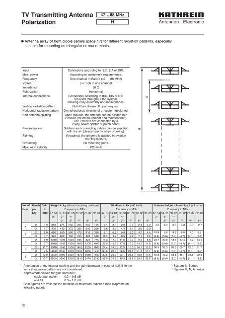
TV Transmitting Antenna<br />
Polarization<br />
47…88 MHz<br />
H<br />
l Antenna array of bent dipole panels (page 17) for different radiation patterns, especially<br />
suitable for mounting on triangular or round masts.<br />
Input<br />
Max. power<br />
Frequency<br />
VSWR<br />
Impedance<br />
Polarization<br />
Internal connections<br />
Vertical radiation pattern<br />
Horizontal radiation pattern<br />
Half antenna splitting<br />
Pressurization<br />
Painting<br />
Grounding<br />
Max. wind velocity<br />
Connectors according to IEC, EIA or DIN.<br />
According to customer’s requirements.<br />
One channel in Band I (47 … 88 MHz)<br />
s < 1.05 in one channel<br />
50 Ω<br />
Horizontal<br />
Connectors according to IEC, EIA or DIN<br />
are used throughout the system,<br />
allowing easy assembly and maintenance.<br />
Null fill and beam tilt upon request.<br />
Omnidirectional, directional or custom-designed.<br />
Upon request, the antenna can be divided into<br />
2 halves (for measurement and maintenance).<br />
The 2 halves are connected by a<br />
2-way power splitter or patch panel.<br />
Splitters and connecting cables can be supplied<br />
with dry air (please specify when ordering).<br />
If required, the antenna is painted in aviation<br />
warning colours.<br />
Via mounting parts.<br />
225 km/h<br />
H<br />
S<br />
No. of Panels Gain* Weight in kg (without mounting hardware) Windload in kN (160 km/h) Antenna height H in m (Spacing S in m)<br />
bays per in Frequency in MHz Frequency in MHz Frequency in MHz<br />
bay dBd 47–54 54–61 60–68 66–72 76–82 82–88 47–54 54–61 60–68 66–72 76–82 82–88 47–54 54–61 60–68 66–72 76–82 82–88<br />
2 1) 3 1) 4 1) 2 1) 3 1) 4 1) 2 1) 3 1) 4 1)<br />
1<br />
2<br />
4<br />
6<br />
8<br />
2 2) 3 2) 4 2) 5 2) 6 2) 2 2) 3 2) 4 2) 5 2) 6 2) 2 2) 3 2) 4 2) 5 2) 6 2)<br />
2 3.9 310 275 250 235 205 195 4.1 3.3 2.9 2.7 2.4 2.2 4.5 4.0 3.6 3.3 2.9 2.7<br />
3 1.7 470 410 375 350 310 290 5.6 4.9 4.4 4.1 3.6 2.9<br />
2 6.9 650 550 500 470 410 390 8.1 6.5 5.8 5.3 4.7 4.4 10.9 9.6 8.6 8.0 7.0 6.5<br />
3 4.7 990 820 750 700 620 580 11.3 9.9 8.9 8.2 7.1 5.9 (6.4) (5.6) (5.0) (4.7) (4.1) (3.8)<br />
2 9.9 1310 1095 1000 935 825 775 16.3 13.0 11.6 10.7 9.4 8.8 23.7 20.8 18.6 17.4 15.2 14.1<br />
3 7.7 1910 1645 1500 1405 1235 1165 22.5 19.8 17.8 16.3 14.3 11.8 (6.4) (5.6) (5.0) (4.7) (4.1) (3.8)<br />
2 11.7 1910 1645 1500 1405 1235 1165 24.4 19.5 17.3 16.0 14.1 13.2 36.5 32.0 28.6 26.7 23.3 21.7<br />
3 9.5 2820 2645 2250 2105 1855 1745 33.8 29.6 26.6 24.5 21.4 17.7 (6.4) (5.6) (5.0) (4.7) (4.1) (3.8)<br />
2 12.9 2600 2190 2000 1870 1650 1550 32.5 26.0 23.1 21.3 18.8 17.6 49.3 43.2 38.6 36.1 31.5 29.3<br />
3 10.7 3800 3290 3000 2810 2470 2330 45.0 39.5 35.5 32.6 28.5 23.5 (6.4) (5.6) (5.0) (4.7) (4.1) (3.8)<br />
* Attenuation of the internal cabling and the gain-decrease in case of null fill in the<br />
vertical radiation pattern are not considered.<br />
Approximate values for gain decrease:<br />
cable attenuation: 0.2 – 0.5 dB<br />
null fill:<br />
0.3 – 1.0 dB<br />
Gain figures are valid for the direction of maximum radiation (see diagrams on<br />
following page).<br />
1)<br />
System B, Europa<br />
2)<br />
System M, N, America<br />
12