K&F SEQUENZA 10 N/W/B & Flying Frame - Kling und Freitag
K&F SEQUENZA 10 N/W/B & Flying Frame - Kling und Freitag
K&F SEQUENZA 10 N/W/B & Flying Frame - Kling und Freitag

Create successful ePaper yourself
Turn your PDF publications into a flip-book with our unique Google optimized e-Paper software.
K&F <strong>SEQUENZA</strong> <strong>10</strong> N/W/B & <strong>Flying</strong> <strong>Frame</strong><br />
User‘s Manual<br />
Version 6.0.<br />
Released: 29.01.20<strong>10</strong><br />
Important Information,<br />
Please Read before Use!<br />
KLING & FREITAG GmbH<br />
Junkersstrasse 14<br />
D-30179 Hannover<br />
PHONE +49 (0) 511- 96 99 70<br />
FAX +49 (0) 511- 67 37 94<br />
www.kling-freitag.de
User's manual<br />
K&F <strong>SEQUENZA</strong> <strong>10</strong> N/W/B & <strong>Flying</strong> <strong>Frame</strong><br />
Table of contents<br />
1 Introduction 6<br />
1.1 Symbols in User's Manual 6<br />
1.2 Information about this User's Manual 6<br />
2 ScopeofDelivery 7<br />
2.1 Scope of Delivery <strong>SEQUENZA</strong> <strong>10</strong> N/W 7<br />
2.2 Scope of Delivery <strong>SEQUENZA</strong> <strong>10</strong> B 7<br />
2.3 Scope of Delivery <strong>SEQUENZA</strong> <strong>10</strong> <strong>Flying</strong> <strong>Frame</strong> 7<br />
3 RequiredTools 7<br />
4 SystemRequirementsforUse 7<br />
5 ProductDescription 8<br />
5.1 <strong>SEQUENZA</strong> <strong>10</strong> N/W 8<br />
5.1.1 Overview <strong>SEQUENZA</strong> <strong>10</strong> N/W Parts 8<br />
5.2 <strong>SEQUENZA</strong> <strong>10</strong> B 9<br />
5.2.1 Overview <strong>SEQUENZA</strong> <strong>10</strong> B Parts 9<br />
5.3 <strong>SEQUENZA</strong> <strong>10</strong> flying frame <strong>10</strong><br />
5.3.1 Overview of flying frame Components <strong>10</strong><br />
6 SafetyInstructions 11<br />
6.1 Safety Instructions for Flown Setup 11<br />
6.2 Safety Instructions for Stacked Setups 12<br />
6.3 Wind Loading 14<br />
6.4 Protecting the Speakers / Operating Safety 15<br />
7 UsingtheQuickReleasePins 16<br />
8 RemovingtheTransportCovers 16<br />
9 PositioningoftheLoadAdapters 16<br />
<strong>10</strong> FlownSetup 18<br />
<strong>10</strong>.1 Combining the Speaker Array 18<br />
<strong>10</strong>.1.1 Array with <strong>SEQUENZA</strong> <strong>10</strong> N/W 18<br />
<strong>10</strong>.1.2 Array with <strong>SEQUENZA</strong> <strong>10</strong> B 22<br />
<strong>10</strong>.1.3 Array with <strong>SEQUENZA</strong> <strong>10</strong> N/W and <strong>SEQUENZA</strong> <strong>10</strong> B 25<br />
<strong>10</strong>.2 Lifting the Array 26<br />
<strong>10</strong>.2.1 Arrays with <strong>SEQUENZA</strong> <strong>10</strong> B 26<br />
<strong>10</strong>.2.2 Arrays with <strong>SEQUENZA</strong> <strong>10</strong> N/W and 5m maximal Length 26<br />
<strong>10</strong>.2.3 Arrays with <strong>SEQUENZA</strong> <strong>10</strong> N/W exceeding a Length of 5m 28<br />
11 FlownDisassembly 30<br />
11.1 Disassembly of arrays with <strong>SEQUENZA</strong> <strong>10</strong> N/W exceeding a Length of<br />
5m 31<br />
KLING & FREITAG GMBH © 2009 Revision 6.0 Page 3 of 65
User's manual<br />
K&F <strong>SEQUENZA</strong> <strong>10</strong> N/W/B & <strong>Flying</strong> <strong>Frame</strong><br />
11.2 Disassembly of arrays with <strong>SEQUENZA</strong> <strong>10</strong> N/W and a maximum Length of<br />
5m 31<br />
12 StackedSetup 32<br />
12.1 <strong>SEQUENZA</strong> <strong>10</strong> N/W stacked 32<br />
12.1.1 Preparing the <strong>Flying</strong> <strong>Frame</strong> 32<br />
12.1.2 Mounting the Speakers 33<br />
12.2 <strong>SEQUENZA</strong> <strong>10</strong> B stacked 36<br />
12.3 <strong>SEQUENZA</strong> <strong>10</strong> N/W stacked on <strong>SEQUENZA</strong> <strong>10</strong> B 37<br />
13 DisassamblingtheStackedArray 38<br />
14 CardioidArrayswith<strong>SEQUENZA</strong><strong>10</strong>B 38<br />
14.1 Setup instructions for a cardioid array 39<br />
14.2 Controller setups for cardioid use 41<br />
15 <strong>SEQUENZA</strong><strong>10</strong>BcombinedwithotherK&Ftops. 41<br />
16 Fuseinthe<strong>SEQUENZA</strong><strong>10</strong>B 42<br />
16.1 Replacing the Fuses 42<br />
17 Wiring 42<br />
17.1 Cabling a K&F System Rack 42<br />
17.2 Connecting the <strong>SEQUENZA</strong> <strong>10</strong> N/W 43<br />
17.3 Connecting the <strong>SEQUENZA</strong> <strong>10</strong> B 44<br />
17.4 Fixating the Cables 45<br />
18 TransportandStorage 45<br />
19 MaintenanceandCare 45<br />
19.1 Inspection Intervals and Items 46<br />
20 OptionalBGVC1Certification 46<br />
21 TechnicalSpecificationsofLoudspeakers 47<br />
21.1 Technical Specifications <strong>SEQUENZA</strong> <strong>10</strong> N 47<br />
21.2 Technical Specifications <strong>SEQUENZA</strong> <strong>10</strong> W 48<br />
21.3 Technical Specifications <strong>SEQUENZA</strong> <strong>10</strong> B 49<br />
22 Measuringdiagrams 50<br />
22.1 <strong>SEQUENZA</strong> <strong>10</strong> N diagrams 50<br />
22.2 <strong>SEQUENZA</strong> <strong>10</strong> W diagrams 52<br />
22.3 <strong>SEQUENZA</strong> <strong>10</strong> B diagrams 54<br />
23 Dimensionsspeaker 56<br />
23.1 Dimensions <strong>SEQUENZA</strong> <strong>10</strong> N/W 56<br />
23.2 Dimensions <strong>SEQUENZA</strong> <strong>10</strong> B 57<br />
24 Dimensionsandweightflyingframe 58<br />
25 Accessories 59<br />
25.1 General Accessories for <strong>SEQUENZA</strong> <strong>10</strong> 59<br />
KLING & FREITAG GMBH © 2009 Revision 6.0 Page 4 of 65
User's manual<br />
K&F <strong>SEQUENZA</strong> <strong>10</strong> N/W/B & <strong>Flying</strong> <strong>Frame</strong><br />
25.2 Accessories for <strong>SEQUENZA</strong> <strong>10</strong> N/W 60<br />
25.3 Accessories for <strong>SEQUENZA</strong> <strong>10</strong> B 61<br />
25.4 Accessories for <strong>SEQUENZA</strong> <strong>10</strong> <strong>Flying</strong> <strong>Frame</strong> 62<br />
26 Disposal 63<br />
26.1 Regulations for Disposal 63<br />
26.1.1 Germany 63<br />
26.1.2 EU, Norway, Iceland, and Liechtenstein 63<br />
26.1.3 All other Countries 63<br />
27 DeclarationofConformity(CE) 64<br />
27.1 CE Rigging System 64<br />
27.2 CE Loudspeaker 65<br />
KLING & FREITAG GMBH © 2009 Revision 6.0 Page 5 of 65
User's manual<br />
K&F <strong>SEQUENZA</strong> <strong>10</strong> N/W/B & <strong>Flying</strong> <strong>Frame</strong><br />
1. Introduction<br />
Thank you for your decision to buy a KLING & FREITAG so<strong>und</strong> system. To guarantee a trouble-free operating<br />
of the equipment and to allow your KLING & FREITAG Sequenza <strong>10</strong> system to achieve its full<br />
potential please read the operating instructions carefully before use. With the purchase of a <strong>SEQUENZA</strong><br />
<strong>10</strong> system, you have acquired a large so<strong>und</strong> system with the highest possible quality and performance<br />
capabilities. As the owner of a <strong>SEQUENZA</strong> <strong>10</strong> system, you now have a versatile and highly professional<br />
tool which, when operated properly, is a true pleasure to use.<br />
1.1 SymbolsinUser'sManual<br />
This symbol indicates the possibility of life-threatening danger and a health risk for persons. Not following<br />
these instructions may result in serious health problems including potentially fatal injuries.<br />
Warning<br />
This symbol indicates a possibly dangerous situation. Not following these instructions may cause minor<br />
injuries or cause property damage.<br />
Caution<br />
This symbol gives instructions for the proper use of the described products. Not following these instructions<br />
may cause malfunctions or property damage.<br />
Important<br />
This symbol indicates notes that help you to handle the described products easier.<br />
Tip<br />
1.2 InformationaboutthisUser'sManual<br />
User's Manual <strong>SEQUENZA</strong> <strong>10</strong> N and <strong>SEQUENZA</strong> <strong>10</strong> W in Combination with the <strong>SEQUENZA</strong> <strong>10</strong> <strong>Flying</strong><br />
<strong>Frame</strong>. <strong>SEQUENZA</strong> <strong>10</strong> N/W<strong>SEQUENZA</strong> <strong>10</strong> B<strong>SEQUENZA</strong> <strong>10</strong><br />
© <strong>Kling</strong> & <strong>Freitag</strong> GmbH, 2008, all rights reserved.<br />
All specifications in this manual are based on information available at the time of publishing for the<br />
features and safety guidelines of the described products.<br />
Technical specifications, measurements, weights and properties are not guaranteed.<br />
The manufacturer reserves the right to make product alterations within legal provisions as well as changes<br />
to improve product quality.<br />
Allpersonswhousethespeakersystemmusthavethisguideandallfurtherinformationfor<br />
safeoperationsavailabletothemduringassembly,disassembly,anduse.Thespeakersystem<br />
mayneitherbesetupnoruseduntilthismanualhasbeenread,<strong>und</strong>erstoodandkeptreadily<br />
availableonsite.<br />
We appreciate any input with suggestions and improvements for this manual. Please send this to us at<br />
the following address:<br />
info@kling-freitag.de or to:<br />
KLING & FREITAG GMBH Junkersstr.14 D-30179 Hannover.<br />
Phone +49 (0) 511 - 96 99 70, Fax +49 (0) 511 - 67 37 94<br />
KLING & FREITAG GMBH © 2009 Revision 6.0 Page 6 of 65
User's manual<br />
K&F <strong>SEQUENZA</strong> <strong>10</strong> N/W/B & <strong>Flying</strong> <strong>Frame</strong><br />
2. ScopeofDelivery<br />
2.1 ScopeofDelivery<strong>SEQUENZA</strong><strong>10</strong>N/W<br />
• Full-range loudspeaker with integraten 'Snap&Fly' Rigging System incl. Quick Release Pins (usable<br />
with <strong>SEQUENZA</strong> <strong>10</strong> <strong>Flying</strong> <strong>Frame</strong> only)<br />
• User's Manual<br />
2.2 ScopeofDelivery<strong>SEQUENZA</strong><strong>10</strong>B<br />
• Subwoofer with integraten Rigging System incl. Quick Release Pins (usable with <strong>SEQUENZA</strong> <strong>10</strong><br />
<strong>Flying</strong> <strong>Frame</strong> only)<br />
• User's Manual<br />
2.3 ScopeofDelivery<strong>SEQUENZA</strong><strong>10</strong><strong>Flying</strong><strong>Frame</strong><br />
• <strong>Flying</strong> frame to hang and stack <strong>SEQUENZA</strong> <strong>10</strong> N/W speakers incl. Quick Release Pins <strong>SEQUENZA</strong><br />
<strong>10</strong><br />
• 2 x 3.25t shackles (for optional safety chain)<br />
• User's Manual<br />
• Calculation software CON:<strong>SEQUENZA</strong> CON:<strong>SEQUENZA</strong><br />
The following material is optionally available for flying the flying frame:<br />
• 3 level-adjustable hinged heavy-duty feet (mandatory for stacking speakers)<br />
• 2 x 3.25t shackle for load adapter<br />
• 2-strand safety chain: 2 x 8mm steel chain / Grade 8 / Length 380mm per strand (Working load<br />
limit (WLL) BGV C1: 1250 kg) with 2 x hooks DIN 5691 WLL BGV C1: 1250 kg) / Rigging link<br />
shape A according to DIN 56882 (WLL BGV C1: 1750 kg)<br />
3. RequiredTools<br />
For the optionally available hinged heavy-duty feet of the <strong>SEQUENZA</strong> <strong>10</strong> flying frame:<br />
• 24 mm open-end wrench<br />
• 17 mm open-end wrench<br />
4. SystemRequirementsforUse<br />
ConnectorPanelCP4<br />
K&FCD44DigitalSystemController<br />
LAB.GRUPPENFP<strong>10</strong>000Q:<br />
Thesecomponentswillbereferredtoas'K&FSystemRack'inthismanual.<br />
KLING & FREITAG GMBH © 2009 Revision 6.0 Page 7 of 65
User's manual<br />
K&F <strong>SEQUENZA</strong> <strong>10</strong> N/W/B & <strong>Flying</strong> <strong>Frame</strong><br />
5. ProductDescription<br />
5.1 <strong>SEQUENZA</strong><strong>10</strong>N/W<br />
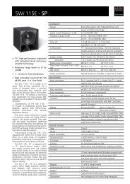
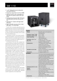
5.1.1 Overview<strong>SEQUENZA</strong><strong>10</strong>N/WParts<br />
1. speaker enclosure<br />
2. Park position Quick Release Pins<br />
3. Quick Release Pins front<br />
4. front joint plates<br />
5. front connector bracket<br />
6. rear joint plate<br />
7. rear connector bracket<br />
8. spring bolt<br />
9. Quick Release Pin rear<br />
KLING & FREITAG GMBH © 2009 Revision 6.0 Page 8 of 65
User's manual<br />
K&F <strong>SEQUENZA</strong> <strong>10</strong> N/W/B & <strong>Flying</strong> <strong>Frame</strong><br />
5.2 <strong>SEQUENZA</strong><strong>10</strong>B<br />
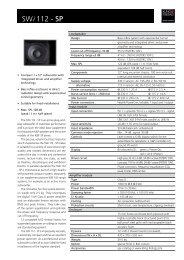
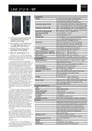
5.2.1 Overview<strong>SEQUENZA</strong><strong>10</strong>BParts<br />
1<br />
2<br />
3<br />
4<br />
5<br />
6<br />
7<br />
1. speaker enclosure<br />
2. Stacking grooves / cover, adjacent: stacking feet / bottom<br />
3. Threaded stand flange<br />
4. Stacking feet / side, adjacent: stacking grooves / side<br />
5. joint plates<br />
6. connector brackets<br />
7. Quick Release Pins in park position<br />
KLING & FREITAG GMBH © 2009 Revision 6.0 Page 9 of 65
User's manual<br />
K&F <strong>SEQUENZA</strong> <strong>10</strong> N/W/B & <strong>Flying</strong> <strong>Frame</strong><br />
5.3 <strong>SEQUENZA</strong><strong>10</strong>flyingframe<br />
This flying frame was designed to fly or stack the KLING & FREITAG speakers <strong>SEQUENZA</strong> <strong>10</strong> N/W. SE-<br />
QUENZA <strong>10</strong><br />
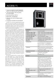
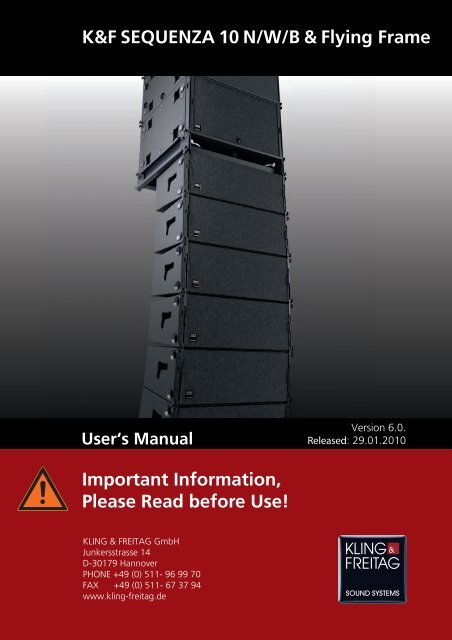
5.3.1 OverviewofflyingframeComponents<br />
1<br />
2<br />
3<br />
4<br />
5<br />
6<br />
7<br />
8<br />
9<br />
<strong>10</strong><br />
1. hinge fitting<br />
2. fixing point for Rieker inclinometer<br />
3. <strong>SEQUENZA</strong> <strong>10</strong> flying frame<br />
4. fixing plate for SSE inclinometer<br />
5. Hinged heavy-duty feet rear (optional)<br />
6. load adapter<br />
7. stacking link<br />
8. Hinged heavy-duty feet front (optional)<br />
9. park position for load adapter<br />
<strong>10</strong>. fixing points for safety chain<br />
KLING & FREITAG GMBH © 2009 Revision 6.0 Page <strong>10</strong> of 65
User's manual<br />
K&F <strong>SEQUENZA</strong> <strong>10</strong> N/W/B & <strong>Flying</strong> <strong>Frame</strong><br />
6. SafetyInstructions<br />
The information described here does not relieve the user of the duty to follow the given safety requirements<br />
and legal regulations.<br />
Warning<br />
The technicians responsible for assembling the flying frame on site are responsible for the safe setup and<br />
use of the flying frame and guarantee this.<br />
To prevent damage to persons and property, you must set up or suspend the array in compliance with<br />
the specifications of the German safety regulation BGV C1 or comparable applicable national standards.<br />
At least 2 people are necessary to set up the array.<br />
The flying frame is solely for professional use and only for the suspension of the KLING & FREITAG<br />
speaker models <strong>SEQUENZA</strong> <strong>10</strong> N, <strong>SEQUENZA</strong> <strong>10</strong> W, <strong>SEQUENZA</strong> <strong>10</strong> B in the manner described here.<br />
If the simulation software CON:<strong>SEQUENZA</strong> displays "Load-Failed", the array may not be set up in the<br />
configuration simulated in the software. CON:<strong>SEQUENZA</strong><br />
When laying out the connecting cables, make sure that nobody can trip.<br />
If not otherwise stated in this manual, only original KLING & FREITAG parts may be used for mounting<br />
the speakers. The use of other parts - in particular parts by other manufacturers - is not permitted.<br />
For mobile and fixed installations, use only assembly equipment from KLING & FREITAG.<br />
As a basic principle, you must visually inspect all components of the array before every use. For fixed<br />
installations, you must inspect all components of the rigging system for signs of wear at regular intervals.<br />
The visual inspection includes checking the components of the speakers, the flying frame, the loadbearing<br />
parts (cross beams, ceiling constructions, etc.) and their bolted connections. When inspecting<br />
components of the flying frame, pay special attention to any deformations, cracks, damage to threads,<br />
and corrosion as well as the functional capability of the Quick Release Pins and the functional capability<br />
of the spring bolts. Mounting devices such as shackles, chains and wire ropes also have to be checked for<br />
signs of wear or deformation carefully. If there are signs of wear, cracks, or deformation, etc. then you<br />
must replace the parts immediately. For further instructions, refer to chapter "Maintenance and Care"<br />
on page 45.<br />
6.1 SafetyInstructionsforFlownSetup<br />
Fallingspeakersposethethreatoffatalinjuriestopeoplenearthem!<br />
Ifyouhaveeventheslightestreasontodoubtthesafetyoftheriggingsystem,thenyoumay<br />
notuseit<strong>und</strong>eranycircumstance.<br />
Warning<br />
Onlytrainedeventtechniciansmaysuspendtheflyingframe.<br />
Never suspend the speakers without the appropriate flying frame.<br />
The maximum working load limit (WLL) of the flying frame is – depending on the selected load bearing<br />
drillings and types of speakers – 625kg-<strong>10</strong>00kg.<br />
This specification includes cabling and additional fittings. The provided simulation software<br />
'CON:<strong>SEQUENZA</strong>' must be used to determine if the frame is loaded permissibly. The simulation software<br />
CON:<strong>SEQUENZA</strong> does not take the weight of cabling and additional fittings into consideration! When<br />
following the specifications of the CON:<strong>SEQUENZA</strong> calculation software, consider this additional weight<br />
and reduce the number of speakers accordingly.<br />
If the simulation software does not confirm the compliance with DIN 18 800, the array may not be<br />
assembled in the simulated setup.<br />
KLING & FREITAG GMBH © 2009 Revision 6.0 Page 11 of 65
User's manual<br />
K&F <strong>SEQUENZA</strong> <strong>10</strong> N/W/B & <strong>Flying</strong> <strong>Frame</strong><br />
If the simulation software CON:<strong>SEQUENZA</strong> does not confirm the compliance with BGV C1, no one may<br />
be situated in this area between the assembly and disassembly – not even those involved in assembly<br />
and disassembly. You must effectively block off this area and secure it from trespassing.<br />
Warning<br />
The following arrays (maximum configurations) fulfil the stipulations of the BGV C1 with their given<br />
design:<br />
Maximumnumberofflownspeakers:<br />
• <strong>SEQUENZA</strong><strong>10</strong>Nand<strong>SEQUENZA</strong><strong>10</strong>W:<br />
Arrays of up to 13 speakers and a flying frame inclination less than +/- 4°.<br />
• <strong>SEQUENZA</strong><strong>10</strong>B:<br />
Arrays of up to 12 speakers.<br />
• <strong>SEQUENZA</strong><strong>10</strong>N/Wcombinedwith<strong>SEQUENZA</strong><strong>10</strong>B:<br />
For combined arrays consisting of <strong>SEQUENZA</strong> <strong>10</strong> N/W and <strong>SEQUENZA</strong> <strong>10</strong> B, a special verification<br />
with the CON:<strong>SEQUENZA</strong> simulation software is mandatory.<br />
If these angles or the number of speakers is exceeded, it is mandatory that you separately verify the array<br />
with the CON:<strong>SEQUENZA</strong> simulation software. CON:<strong>SEQUENZA</strong><br />
Ensure that all connections are secured against coming loose and that only authorized, statically tested<br />
and correctly sized supports, mounting equipment, wire ropes and chains are used.<br />
Follow the relevant specified safety factors. The safety factors (SF) are stated on the back of the speakers<br />
and they comply with the BGV C1. Be sure to follow the relevant national specifications, norms, and<br />
safety regulations.<br />
Note that every suspension point as well as the supporting structure of the building (i.e. ceiling points,<br />
cross beams and stage or PA tower, etc.) must be capable of carrying the total load of the system (including<br />
cabling and additional fittings).<br />
Note that the suspension points on the hall ceiling (i.e. shackles, suspension points, or chain points)<br />
must comply with the accident prevention regulation BGV C1 (Event and Production Sites for Stage<br />
Presentations) or comparable applicable national standards, and the total load must be approved by an<br />
authorised expert. If in doubt, have it checked by local authorities.<br />
Also, follow the operating and safety instructions for the product from which you will suspend the flying<br />
frame (i.e. truss). If there is no information regarding the safe use and the working load limit, you may<br />
not fly the flying frame from it.<br />
Every chain and every motor must be capable of carrying the total load of the array on its own, even<br />
with two-strand rigging. Check to make sure that the chains of the hoist motors are hanging straight<br />
down and are not twisted and that the hoist motors are in the intended positions.<br />
When operating with chain hoists that do not comply with the BGV C1 or the D8+, no one may be<br />
present in the danger zone <strong>und</strong>erneath or near the speaker array.<br />
Secure the array from falling with a second independent safety fitting if no BGV C1 or D8+ motor is used.<br />
Never use signal cables or power cords for suspending, aligning or securing the systems. When laying<br />
out the connecting cables, make sure that nobody can trip.<br />
Make sure you have enough free working space on site to assemble and suspend the array.<br />
The array can swing out while being lifted!<br />
Only personnel directly involved with assembly or disassembly may be in the working area. Every time<br />
before the responsible technician raises or lowers the flying frame, he must unmistakably signal this to<br />
all people. All persons must then move outside of the pivoting and lifting range.<br />
The flying frame may not be used to lift and secure people or objects other than the above-mentioned<br />
speaker systems.<br />
The array may not be used as a climbing aid.<br />
The safe use of the flying frame and the speakers also depends on the various factors present at the<br />
area of use. Weather conditions such as wind or rain, for example, can compromise the safety of the<br />
flying frame and speakers. Always consider and evaluate these factors. (See chapter "Wind Loading"<br />
on page 14.)<br />
KLING & FREITAG GMBH © 2009 Revision 6.0 Page 12 of 65
User's manual<br />
K&F <strong>SEQUENZA</strong> <strong>10</strong> N/W/B & <strong>Flying</strong> <strong>Frame</strong><br />
6.2 SafetyInstructionsforStackedSetups<br />
Fallingspeakersposethethreatoffatalinjuriestopeoplenearthem!<br />
Be sure to follow the relevant national specifications, norms, and safety regulations.<br />
Warning<br />
Always make sure that a sufficient safety level is still given, even when outside forces have an additional<br />
impact on the stacked speakers. Before setup, carefully ascertain if there are any possible outside forces<br />
that could result in the array falling over. (Slant of the gro<strong>und</strong> / the bearing capacity of the gro<strong>und</strong> /<br />
wind / person or vehicle impact, etc.). A technical expert who is responsible for the setup must evaluate<br />
and determine necessary measures (including calculating the statics). If necessary, obtain expert proof<br />
of stability.<br />
For the standard safety inspection, you must always factor in an imperfection (tilt) of +/-5° and destabilising<br />
loads. A planned tilt of the flying frame ist not permissible. In calculations, the tilted setup serves<br />
the purpose of levelling out unevenness.<br />
With the set-up systems for which you cannot verify the structural safety without safeguards, you must<br />
secure them to prevent sliding or tipping in order to provide proof of this safety. To secure the system from<br />
tipping over, use water tanks or floor bolts. Other possible measures include strapping it to a suitable<br />
substructure or tying it using safety straps. The simulation in the CON:<strong>SEQUENZA</strong> software is not valid<br />
as a verification of structural safety. This software always states that you must secure stacked speakers<br />
to prevent their falling over.<br />
For outdoor and trade fair venues in which wind loads must be considered, additional proof of stability<br />
is necessary.<br />
Only stack the <strong>SEQUENZA</strong> <strong>10</strong> N/W systems in conjunction with the <strong>SEQUENZA</strong> <strong>10</strong> flying frame and<br />
the optionally available <strong>SEQUENZA</strong> <strong>10</strong> Gro<strong>und</strong> Stack Kit (stacking feet), which is intended to be used.<br />
Stacking of <strong>SEQUENZA</strong> <strong>10</strong> N/W without the optional feet is not permissible!<br />
Make sure that the stacking feet of subwoofers stacked on top of one another are securely positioned<br />
in the grooves of the lower speaker.<br />
Maximumnumberofstackedspeakers(Valid for indoor operations without wind, with a person<br />
impact of <strong>10</strong> kg at a height of 1.5 m and a flying frame tilt of 5°):<br />
• <strong>SEQUENZA</strong><strong>10</strong>Nand<strong>SEQUENZA</strong><strong>10</strong>W:<br />
arrays with up to 7 x <strong>SEQUENZA</strong> <strong>10</strong> N/W. To fixate the system to the floor, you can use the<br />
openings in the optional stacking feet (<strong>SEQUENZA</strong> <strong>10</strong> Gro<strong>und</strong> Stack Kit).<br />
• <strong>SEQUENZA</strong><strong>10</strong>Bflat:<br />
Arrays with up to 6 x <strong>SEQUENZA</strong> <strong>10</strong> B<br />
• <strong>SEQUENZA</strong><strong>10</strong>Bvertical:<br />
Arrays with up to 2 x <strong>SEQUENZA</strong> <strong>10</strong> BYou must additionally secure vertically standing stacked<br />
<strong>SEQUENZA</strong> <strong>10</strong> B systems from falling since the structural safety is not guaranteed, otherwise.<br />
Possible measures include strapping them to a suitable substructure or tying them using safety<br />
straps.<br />
• <strong>SEQUENZA</strong><strong>10</strong>N/Wcombinedwith<strong>SEQUENZA</strong><strong>10</strong>B<br />
arrays with up to 7 x <strong>SEQUENZA</strong> <strong>10</strong> N/W on 6 x <strong>SEQUENZA</strong> <strong>10</strong> B.<br />
<strong>SEQUENZA</strong><strong>10</strong>B<br />
If you are stacking a K&F top with feet (i.e. Line 212) on top of a <strong>SEQUENZA</strong> <strong>10</strong> B subwoofer that is placed<br />
on its side, make sure that the Quick Release Pins have not been damaged in their stand-by positions.<br />
You must always strap such setups to one another and secure them from falling over.<br />
KLING & FREITAG GMBH © 2009 Revision 6.0 Page 13 of 65
User's manual<br />
K&F <strong>SEQUENZA</strong> <strong>10</strong> N/W/B & <strong>Flying</strong> <strong>Frame</strong><br />
6.3 WindLoading<br />
For open air events, obtain current local wind and weather data. The following chart provides a preliminary<br />
indication<br />
Bft m/s Windspeed Description<br />
0 0-0.2 Calm Smoke rises vertically<br />
1 0.3-1.5 Light air Smoke drift indicates<br />
wind direction, vanes do<br />
not move<br />
2 1.6-3.3 Light Wind felt on face, vanes<br />
begin to move<br />
3 3.4-5.4 Gentle Leaves, small twigs in<br />
constant motion, light<br />
flags extended<br />
4 5.5-7.9 Moderate Dust, leaves, and loose<br />
paper raised up, small<br />
branches move<br />
5 8.0-<strong>10</strong>.7 Fresh Small trees in leaf begin<br />
to sway, whitecaps<br />
on lakes visible<br />
6 <strong>10</strong>.8-13.8 Strong Larger branches of trees<br />
in motion; whistling<br />
heard in wires<br />
7 13.9-17.1 Near gale Whole trees in motion;<br />
resistance felt in walking<br />
against wind<br />
8 17.2-20.7 Gale Twigs and small branches<br />
broken off trees<br />
For outdoor uses, we recommend using at least a BGV D8+ hoisting device to avoid wind causing the<br />
release of the secondary safety device.<br />
Warning<br />
If wind speeds higher than Beaufort 5 are expected, you must constantly consider the wind speed and its<br />
possible influence on the array as well as the fact that the wind speed increases the higher the array is.<br />
With expected wind speeds exceeding Beaufort 5, construct the rigging and safety points so that they<br />
can carry at least twice the static load.<br />
With wind speeds exceeding Beaufort 6 (14 m/sec.), arrays are not recommended.<br />
As of a wind speed of Beaufort 6, you must clear the area <strong>und</strong>er the speakers. Effectively prevent the<br />
arrays from swaying in the wind by tying them off or using a lateral fixation. If the suspended load sways,<br />
it can create significant inertial force that can result in the PA tower structurally collapsing or tipping.<br />
With wind speeds of Beaufort 8 or more, you must lower and disassemble the array.<br />
KLING & FREITAG GMBH © 2009 Revision 6.0 Page 14 of 65
User's manual<br />
K&F <strong>SEQUENZA</strong> <strong>10</strong> N/W/B & <strong>Flying</strong> <strong>Frame</strong><br />
6.4 ProtectingtheSpeakers/OperatingSafety<br />
<strong>SEQUENZA</strong> <strong>10</strong> speakers may only be used in combination with a K&F SystemRack. See chapter [System<br />
Requirements for Use] on page 7.<br />
Caution<br />
In general, audio signals should not be overdriven. This may be caused by mixing consoles, equalizers,<br />
effect equipment, etc. and should be indicated on this equipment. When a power amplifier is overloaded<br />
at the output (clipping), then the amplifier activates a clipping warning signal. In any case, the signal<br />
must be reduced as soon as it so<strong>und</strong>s unnaturally distorted.<br />
Fordamagecausedby<br />
• overloading the speakers<br />
• The rear-facing subwoofer is controlled using the Controller CD 44 via LSBlock for cardioid / hypercardioid<br />
arrays for rear-emitting subwoofers. The front-facing subwoofers are controlled via<br />
LSBlock for cardioid / hypercardioid arrays for front-emitting subwoofers.<br />
we do not assume warranty and excludes liability for possible consequential damage.<br />
Thefollowingsignalsmaydamagethespeakers:<br />
• permanent high-level signals with high frequency and continuous noise from feedback.<br />
• permanently distorted high-level signals.<br />
• noises, which occur when the amplifier is on while equipment is being con-nected, disconnected<br />
or switched on.<br />
Donotinstalldevicesinanyofthefollowingplaces:<br />
• where the devices are permanently exposed to direct sunlight.<br />
• where the devices are exposed to high moisture or rain.<br />
• where the devices are exposed to strong vibrations and dust.<br />
Damagecausedbythespeakers'magneticfields<br />
Speakers are permanently surro<strong>und</strong>ed by a magnetic field, even when they are not connected. Therefore,<br />
during transport and placement of the speakers, it is important to ensure that there is always approx. 1<br />
m between the speakers and magnetic data media and computer/video monitors.<br />
Preventinghearingdamage<br />
Avoid beeing too close to operating speakers. Even loudness levels of approx. 90 dB - that you subjectively<br />
judge as being low - can lead to hearing damage.<br />
KLING & FREITAG GMBH © 2009 Revision 6.0 Page 15 of 65
User's manual<br />
K&F <strong>SEQUENZA</strong> <strong>10</strong> N/W/B & <strong>Flying</strong> <strong>Frame</strong><br />
7. UsingtheQuickReleasePins<br />
The Quick Release Pins are equipped with retaining balls. By pushing the button in the middle of the pin,<br />
you can release these balls and then insert or remove the pin. As long as you do not push the button in<br />
the middle of the pin, you should not be able to pull out the pin.<br />
8. RemovingtheTransportCovers<br />
In order to remove the transport cover, push the<br />
latch in the ro<strong>und</strong> opening towards the middle of<br />
the transport cover (1), slightly pull the transport<br />
cover on the side of the latch toward you (2), and<br />
remove the cover to the side (3).<br />
When doing this, do not pull the transport cover towards<br />
you too much, as this could cause the catch<br />
on the other side of the cover to bend.<br />
1<br />
3<br />
2<br />
9. PositioningoftheLoadAdapters<br />
You can calculate one- and two-strand riggings with the simulation software CON:<strong>SEQUENZA</strong>. For onestrand<br />
rigging, use one load adapter; for two-strand rigging, use two load adapters.<br />
The drill holes on the flying frame where the load adapters are to be attached are determined by the<br />
simulation software CON:<strong>SEQUENZA</strong>. CON:<strong>SEQUENZA</strong>You will find the specifications on the relevant<br />
calculation printouts. The specification of the drill hole in the simulation software refers to the drill hole<br />
in the load adapter that is facing the front side of the frame. The front side of the frame is marked with<br />
a sticker (Front).<br />
KLING & FREITAG GMBH © 2009 Revision 6.0 Page 16 of 65
TO BE USED BY QUALIFIED<br />
RIGGERS ONLY !<br />
READ MANUAL AND SAFETY<br />
INSTRUCTIONS BEFORE USE !<br />
SUSPEND K&F <strong>SEQUENZA</strong> <strong>10</strong><br />
Manufacturing Year:<br />
Weight:<br />
Ser.-No.:<br />
41kg<br />
(BGV C1 / SF 5 / SECONDARY SAFETY)<br />
MINIMUM 625 kg<br />
@ALL HOLE POSITIONS<br />
MAXIMUM <strong>10</strong>00 KG<br />
FROM HOLE POSITION 1 TO 21<br />
SECURE FRAME WITH A<br />
SECONDARY 2 LEG SAFETY !<br />
MODEL:<br />
User's manual<br />
K&F <strong>SEQUENZA</strong> <strong>10</strong> N/W/B & <strong>Flying</strong> <strong>Frame</strong><br />
The drill holes in the flying frame are numbered consecutively from 1 to 27, beginning on the front end<br />
of the frame (Front). For your orientation, the drill holes 5, 9, 15, 20, and 26 are labelled.<br />
You can set the position of the load adapters in 1/2-steps because they are usable on both sides. This<br />
doubles the grid of the row of drill holes in the flying frame and thus the adjustment possibilities. The<br />
load adapters are labelled with '1/1 Grid' on the one side and '1/2 Grid' on the other. The simulation<br />
software CON:<strong>SEQUENZA</strong> gives you the information whether a load adapter should be mounted in the<br />
1/1 or the 1/2 position. In the 1/1 position (A), the arrow on the 1/1 side of the load adapter must point<br />
toward the front side of the flying frame (Front). In the 1/2 position (B), the arrow on the 1/2 side of the<br />
load adapter must point toward the front side of the flying frame (Front).<br />
A<br />
B<br />
1, 2, 3, 4, 5, 6, 7, 8, 9,<strong>10</strong>...............15................20........................27<br />
5 9<br />
SAVE WORKING LOAD:<br />
B<br />
A<br />
STACKING<br />
FLYING 0°<br />
FLYING +3°<br />
15 20<br />
STACKING TABLE<br />
INCLINATION<br />
CABINET A B<br />
7° 2.9° -2.4°<br />
6° 2.0° -3.2°<br />
5° 0.9° -4.4°<br />
4° 0.0° -5.2°<br />
3° -1.1° -6.4°<br />
2° -2.0° -7.3°<br />
<strong>SEQUENZA</strong> <strong>10</strong><br />
1° -3.1° -8.5° FLYING FRAME 24<br />
0° -4.0° -9.2°<br />
26<br />
REAR FOOT<br />
PINS ONLY !<br />
CABLE PICK<br />
AND<br />
ADJUSTMENT<br />
POINT<br />
A = Load adapter 1/1 grid position<br />
B = Load adapter 1/2 grid position<br />
Instructionsformountingtheloadadapter<br />
Important<br />
Calculate the correct position of load adapters with the simulation software CON:<strong>SEQUENZA</strong>.<br />
CON:<strong>SEQUENZA</strong>In this position, the array is guaranteed to fly at the desired angle later, and the so<strong>und</strong><br />
will be emitted correctly.<br />
Alwaysmountaloadadapterwith2QuickReleasePins!<br />
Warning<br />
Take the load adapter (A) out of the standby<br />
position and place it on the hole position<br />
that was determined by the simulation software<br />
CON:<strong>SEQUENZA</strong>.<br />
Mount the load adapter with 2 Quick Release Pins<br />
(A).<br />
With a two-strand rigging, proceed with the second<br />
load adapter accordingly.<br />
KLING & FREITAG GMBH © 2009 Revision 6.0 Page 17 of 65
User's manual<br />
K&F <strong>SEQUENZA</strong> <strong>10</strong> N/W/B & <strong>Flying</strong> <strong>Frame</strong><br />
<strong>10</strong>. FlownSetup<br />
<strong>10</strong>.1 CombiningtheSpeakerArray<br />
<strong>10</strong>.1.1 Arraywith<strong>SEQUENZA</strong><strong>10</strong>N/W<br />
The splay angles of the individual speakers are determined by the simulation software CON:<strong>SEQUENZA</strong>.<br />
CON:<strong>SEQUENZA</strong>You will find the specifications on the relevant calculation printouts. On the rear joint<br />
plate of the speakers, there are drill holes with the corresponding angles marked.<br />
During setup, check every Quick Release Pin to ensure that it is locked in place by pulling it outwards!<br />
Warning<br />
1. Slide the front joint plates out of the speaker<br />
by reaching into the access opening (A) and<br />
pushing the joint plate forwards.<br />
Secure the joint plates(B) with the Quick Release<br />
Pins(C).<br />
2. Slide the speakers together so that the joint<br />
plates protrude into the front connecting<br />
bracket.<br />
KLING & FREITAG GMBH © 2009 Revision 6.0 Page 18 of 65
User's manual<br />
K&F <strong>SEQUENZA</strong> <strong>10</strong> N/W/B & <strong>Flying</strong> <strong>Frame</strong><br />
3. Secure the connection with the Quick Release<br />
Pins.<br />
Make sure all pins fit correctly and are locked<br />
into place.<br />
4. Proceed accordingly with all speakers in the<br />
array.<br />
5. Pull the rear Quick Release Pins of all speakers<br />
out of the stand-by position.<br />
6. Pull out the spring bolts of all speakers<br />
and turn them by 90° to a vertical position<br />
(open).<br />
KLING & FREITAG GMBH © 2009 Revision 6.0 Page 19 of 65
User's manual<br />
K&F <strong>SEQUENZA</strong> <strong>10</strong> N/W/B & <strong>Flying</strong> <strong>Frame</strong><br />
7. Align the drill hole in the joint plate with the<br />
drill hole that is marked with the desired angle.<br />
Connect them using the Quick Release Pin<br />
(A) and make sure the pin fits correctly and<br />
is locked into place.<br />
8. Arrays with a maximal length of 5m<br />
(correspondingtoanarraywithmax.16<br />
x<strong>SEQUENZA</strong><strong>10</strong>N/Wincl.flyingframe):<br />
Turn all spring bolts (B) by 90° to a horizontal<br />
position (closed), so that they snap into<br />
the guide slot of the spring bolt enclosure.<br />
The spring bolts have not yet snapped into<br />
the drill hole of the rear joint plate. The<br />
spring bolts, however, are all set so that they<br />
automatically snap into place when you fly<br />
the array, then creating a positive connection<br />
with the selected angle position.<br />
Arrayswithalengthexceeding5m(correspondingtoanarraywithmorethan<br />
16 x <strong>SEQUENZA</strong> <strong>10</strong> N/W incl. flying<br />
frame):<br />
Leave the spring bolts (B) in the vertical position.<br />
9. Stand the flying frame up vertically and remove<br />
the Quick Release Pins<br />
KLING & FREITAG GMBH © 2009 Revision 6.0 Page 20 of 65
User's manual<br />
K&F <strong>SEQUENZA</strong> <strong>10</strong> N/W/B & <strong>Flying</strong> <strong>Frame</strong><br />
Caution<br />
<strong>10</strong>.<br />
Tipping of the flying frame with speakers can result in injuries. To prevent the frame from tipping<br />
forward with the first speaker, always connect the speakers to one another first before connecting<br />
the flying frame.<br />
To prevent the frame from tipping forward with the first speaker, let the spring bolts of the first two<br />
speakers snap into place before connecting the flying frame.<br />
To do so, you must position the spring bolt of the second speaker horizontally and you may need<br />
to tilt the speaker slightly until the spring bolt snaps into place.<br />
11. Place the frame in front of the top speaker<br />
so that all joint plates (1) protrude into the<br />
frame, then connect them using the Quick<br />
Release Pins (2).<br />
12. Insert the rear joint plate (1) of the top<br />
speaker between the drill holes for the desired<br />
angle, and secure it with the Quick Release<br />
Pin (2).<br />
The tilt angle of the speakers relative to the<br />
flying frame is determined by the simulation<br />
software CON:<strong>SEQUENZA</strong>.<br />
To fly the top speaker parallel (0°) to the flying<br />
frame, use the drill hole '<strong>Flying</strong> 0°' (see<br />
illustration).<br />
To tilt the top speaker upwards by +3°, use<br />
the '<strong>Flying</strong> +3°' hole (see illustration).<br />
13. Wire the speakers. Further information in chapter "Wiring" on page 42.<br />
Please find more detailed information for wiring the <strong>SEQUENZA</strong> <strong>10</strong> speaker and configuring the CD<br />
44 in the hardware user's manual for the CD 44.<br />
14. Proceed as described in chapter [Lifting the Array] as of page 26.<br />
KLING & FREITAG GMBH © 2009 Revision 6.0 Page 21 of 65
User's manual<br />
K&F <strong>SEQUENZA</strong> <strong>10</strong> N/W/B & <strong>Flying</strong> <strong>Frame</strong><br />
<strong>10</strong>.1.2 Arraywith<strong>SEQUENZA</strong><strong>10</strong>B<br />
During setup, check every Quick Release Pin to ensure that it is locked in place by pulling it outwards! As<br />
long as you do not push the button in the middle of the pin, you should not be able to pull out the pin.<br />
Warning<br />
You may fly up to max. 12 <strong>SEQUENZA</strong> <strong>10</strong> B on the flying frame.<br />
Connect the speakers as follows:<br />
1. Slide the 4 joint plates out of the speaker<br />
by reaching into the access opening (A) and<br />
pushing the plates forwards.<br />
Secure the joint plates(B) with the Quick Release<br />
Pins(C).<br />
2. If you are planning a cardioid or hypercardioid<br />
use, lay the middle one of the 3 subwoofers<br />
with its rear side onto the wheel<br />
board before you connect the speakers<br />
Further instructions for cardioide or hypercardioide<br />
uses beginning on page 38.<br />
Push the speakers together so that the 4<br />
joint plates of the one speaker protrude into<br />
the corresponding connecting bracket of<br />
the other speaker.<br />
KLING & FREITAG GMBH © 2009 Revision 6.0 Page 22 of 65
User's manual<br />
K&F <strong>SEQUENZA</strong> <strong>10</strong> N/W/B & <strong>Flying</strong> <strong>Frame</strong><br />
3. Connect the speakers, as illustrated, on both<br />
sides with the Quick Release Pins.<br />
You create a speaker connection by using a<br />
total of 8 Quick Release Pins.<br />
Make sure all pins fit correctly and are locked<br />
into place.<br />
4. Proceed accordingly with all speakers in the array.<br />
5. Stand the flying frame up vertically and remove<br />
the Quick Release Pins<br />
6.<br />
To prevent the frame from tipping forward with the first speaker, always connect the speakers to<br />
one another first before connecting the flying frame. Tipping of the flying frame with speakers can<br />
result in injuries.<br />
Caution<br />
KLING & FREITAG GMBH © 2009 Revision 6.0 Page 23 of 65
User's manual<br />
K&F <strong>SEQUENZA</strong> <strong>10</strong> N/W/B & <strong>Flying</strong> <strong>Frame</strong><br />
7. Place the frame in front of the top speaker<br />
so that the joint plates (1) protrude into the<br />
flying frame, then connect them using the<br />
Quick Release Pins (2).<br />
8. Wire the speakers. Further information in chapter "Wiring" on page 42.<br />
Please find more detailed information for wiring the <strong>SEQUENZA</strong> <strong>10</strong> speaker and configuring the CD<br />
44 in the hardware user's manual for the CD 44. <strong>SEQUENZA</strong> <strong>10</strong><br />
9. Proceed as described in chapter [Lifting the Array] as of page 26.<br />
KLING & FREITAG GMBH © 2009 Revision 6.0 Page 24 of 65
User's manual<br />
K&F <strong>SEQUENZA</strong> <strong>10</strong> N/W/B & <strong>Flying</strong> <strong>Frame</strong><br />
<strong>10</strong>.1.3 Arraywith<strong>SEQUENZA</strong><strong>10</strong>N/Wand<strong>SEQUENZA</strong><strong>10</strong>B<br />
1. Create an array with <strong>SEQUENZA</strong> <strong>10</strong> N/W, see chapter [Array with <strong>SEQUENZA</strong> <strong>10</strong> N/W] as of page 18.<br />
2. Create an array with <strong>SEQUENZA</strong> <strong>10</strong> B, see chapter [Array with <strong>SEQUENZA</strong> <strong>10</strong> B] as of page 22.<br />
3. Remove the 4 Quick Release Pins (A) on the<br />
flying frame of the <strong>SEQUENZA</strong> <strong>10</strong> N/W array<br />
and turn out the 4 angled joint plates (B), as<br />
illustrated.<br />
Secure the angled joint plate (B) with the<br />
Quick Release Pin (A) in this position.<br />
Proceed accordingly with the 3 remaining<br />
angled joint plates of the flying frame.<br />
4. Push the <strong>SEQUENZA</strong> <strong>10</strong> N/W array and the<br />
<strong>SEQUENZA</strong> <strong>10</strong> B array together so that all 4<br />
angled joint plates of the flying frame protrude<br />
into the connecting brackets of the<br />
lower <strong>SEQUENZA</strong> <strong>10</strong> B system.<br />
5. Secure all 4 angled joint plates with the remaining<br />
Quick Release Pins on the bottom<br />
<strong>SEQUENZA</strong> <strong>10</strong> B system.<br />
6. Wire the speakers. Further information in chapter "Wiring" on page 42. Please find more detailed<br />
information for wiring the <strong>SEQUENZA</strong> <strong>10</strong> speaker and configuring the CD 44 in the hardware<br />
user's manual for the CD 44. <strong>SEQUENZA</strong> <strong>10</strong><br />
KLING & FREITAG GMBH © 2009 Revision 6.0 Page 25 of 65
User's manual<br />
K&F <strong>SEQUENZA</strong> <strong>10</strong> N/W/B & <strong>Flying</strong> <strong>Frame</strong><br />
7. Proceed as described in chapter [Lifting the Array] as of page 26.<br />
<strong>10</strong>.2 LiftingtheArray<br />
Seetheinstructionsinchapter[SafetyInstructions]frompage11andinthecorresponding<br />
sub-section[SafetyInstructionsforFlownSetup]frompage11.<br />
Warning<br />
<strong>10</strong>.2.1 Arrayswith<strong>SEQUENZA</strong><strong>10</strong>B<br />
Thisdescriptionisvalidforamaximumof12<strong>SEQUENZA</strong><strong>10</strong>Bsystemsconnectedtooneanother.Morethan12<strong>SEQUENZA</strong><strong>10</strong>Bsystemsconnectedtooneanothermaynotbeflown.<br />
1. Attach a certified 3.25 ton shackle for every speaker used.<br />
Secure the shackles against self-loosening (i.e. split pin).<br />
2. Hook the load hook of the hoist chain (i.e. of the hoist motor) into the load adapter's shackle and<br />
begin to lift the array carefully.<br />
3. When the first speakers are at working height, remove the front transport covers.<br />
4. Lift the array evenly and slowly into its operating position so that it cannot swing out during lifting,<br />
then secure it. In doing this, make sure that chain hoists and lifting accessories do not get caught.<br />
Make sure that the speaker cables do not get crimped or get caught.<br />
<strong>10</strong>.2.2 Arrayswith<strong>SEQUENZA</strong><strong>10</strong>N/Wand5mmaximalLength<br />
Thisdescriptionisvalidforarraysthatonlyconsistof<strong>SEQUENZA</strong><strong>10</strong>N/Wsystemsaswellasfor<br />
mixedarraysof<strong>SEQUENZA</strong><strong>10</strong>N/Wand<strong>SEQUENZA</strong><strong>10</strong>Bwhosetotallengthdoesnotexceed<br />
5m.(Anarraywith16x<strong>SEQUENZA</strong><strong>10</strong>N/Wcorrespondstoalengthof5m).<br />
1. Attach a certified 3.25 ton shackle for every speaker used.<br />
Secure the shackles against self-loosening (i.e. split pin).<br />
2. Verify that every spring bolt of the SEQUEN-<br />
ZA <strong>10</strong> N/W are in a horizontal position<br />
(closed), so that they can lock into place<br />
when lifting the array.<br />
3. Hook the load hook of the hoist chain (i.e. of the hoist motor) into the load adapter's shackle and<br />
begin to lift the array carefully.<br />
KLING & FREITAG GMBH © 2009 Revision 6.0 Page 26 of 65
User's manual<br />
K&F <strong>SEQUENZA</strong> <strong>10</strong> N/W/B & <strong>Flying</strong> <strong>Frame</strong><br />
4. Verify that every spring bolt locks into place.<br />
When the spring bolts snap into place, they<br />
make a clearly audible noise and protrude<br />
out of the drill hole on the opposite side.<br />
5. Check that the spring bolts protrude at least 0.5 mm out of the drill holes at the entire circumference<br />
(A).<br />
During lifting, the spring bolts snap into place successively from the flying frame downwards.<br />
If the spring bolts do not properly snap into place, do not hoist the array any further until you have<br />
corrected the error.<br />
Warning<br />
6. When the first speakers are at working height, remove the front transport covers.<br />
7. When the first <strong>SEQUENZA</strong> <strong>10</strong> N/W speakers are at working height, you can attach the protective<br />
weather covers for this speaker model, if necessary.<br />
For outside uses, these optional protective weather covers with hook-and-loop fastener serve as rain<br />
protection for the rear flying mechanics and the cable connections.<br />
8. Lift the array evenly and slowly into its operating position so that it cannot swing out during lifting,<br />
then secure it. In doing this, make sure that chain hoists and lifting accessories do not get caught.<br />
Make sure that the speaker cables do not get crimped or get caught.<br />
KLING & FREITAG GMBH © 2009 Revision 6.0 Page 27 of 65
User's manual<br />
K&F <strong>SEQUENZA</strong> <strong>10</strong> N/W/B & <strong>Flying</strong> <strong>Frame</strong><br />
<strong>10</strong>.2.3 Arrayswith<strong>SEQUENZA</strong><strong>10</strong>N/WexceedingaLengthof5m<br />
Thisdescriptionisvalidforarraysthatonlyconsistof<strong>SEQUENZA</strong><strong>10</strong>N/Wsystemsaswellas<br />
formixedarraysof<strong>SEQUENZA</strong><strong>10</strong>N/Wand<strong>SEQUENZA</strong><strong>10</strong>Bwhosetotallengthexceeds5m.<br />
(Anarraywith16x<strong>SEQUENZA</strong><strong>10</strong>N/Wcorrespondstoalengthof5m).<br />
1. Attach a certified 3.25 ton shackle for every speaker used.<br />
Secure the shackles against self-loosening (i.e. split pin).<br />
2. When connecting the <strong>SEQUENZA</strong> <strong>10</strong> N/W<br />
systems, leave the spring bolts in a vertical<br />
position so that they cannot snap into place<br />
during lifting.<br />
Riskofcrushinghands!<br />
The speakers move towards each other during<br />
lifting.<br />
3. Hook the load hook of the hoist chain (i.e. of the hoist motor) into the load adapter's shackle and<br />
begin to lift the array carefully.<br />
4. Lift the array up far enough so that the<br />
first speaker enclusures begin to touch each<br />
other.<strong>SEQUENZA</strong> <strong>10</strong> N/W<br />
KLING & FREITAG GMBH © 2009 Revision 6.0 Page 28 of 65
User's manual<br />
K&F <strong>SEQUENZA</strong> <strong>10</strong> N/W/B & <strong>Flying</strong> <strong>Frame</strong><br />
5. Position each spring bolt horizontally when<br />
the corresponding speakers touch each other<br />
during lifting.<br />
The spring bolts do not snap into place until the speaker enclosures begin to move apart again<br />
and the preselected angle position is reached. It is possible that this will happen when the array<br />
is relatively high.<br />
6.<br />
Check that the spring bolts protrude at<br />
least 0.5 mm out of the drill holes at the<br />
entire circumference (A).<br />
Warning<br />
7. When the first speakers are at working height, remove the front transport covers.<br />
8. When the first <strong>SEQUENZA</strong> <strong>10</strong> N/W speakers are at working height, you can attach the protective<br />
weather covers for this speaker model, if necessary.<br />
For outside uses, these optional protective weather covers with hook-and-loop fastener serve as rain<br />
protection for the rear flying mechanics and the cable connections.<br />
9. Lift the array evenly and slowly into its operating position so that it cannot swing out during lifting,<br />
then secure it. In doing this, make sure that chain hoists and lifting accessories do not get caught.<br />
Make sure that the speaker cables do not get crimped or get caught.<br />
KLING & FREITAG GMBH © 2009 Revision 6.0 Page 29 of 65
User's manual<br />
K&F <strong>SEQUENZA</strong> <strong>10</strong> N/W/B & <strong>Flying</strong> <strong>Frame</strong><br />
11. FlownDisassembly<br />
1. Basically, you disassemble the array in the reverse order of assembly.<br />
2. Replace each transport cover when the speakers are hanging at working level.<br />
3. Just before the bottom speaker touches the<br />
gro<strong>und</strong>, pull the array in the direction of the<br />
arrow.<br />
This way, you make sure that the array does<br />
not stand on the side of the bottom speaker,<br />
but rather on the castors.<br />
Always make sure that the chain hoist is<br />
hanging vertically during lowering. If you do<br />
not do this, the array could sway suddenly.<br />
Warning<br />
If the system is not standing on the castors,<br />
this could lead to diagonal pull during further<br />
lowering.<br />
4. Lower <strong>SEQUENZA</strong><strong>10</strong>Barrays far enough that all systems are on the wheels, then prepare the<br />
<strong>SEQUENZA</strong> <strong>10</strong> speakers for transport.<br />
• Place the used Quick Release Pins back onto their intended stand-by positions on the speaker<br />
and flying frame.<br />
• Push all joint plates back into the speaker.<br />
• Dismantle all other used components so that they are not exposed and get damaged during<br />
transport.<br />
For arrayswith<strong>SEQUENZA</strong><strong>10</strong>N/Wandalengthexceeding5m, proceed as described in subsection<br />
[Disassembly of arrays with <strong>SEQUENZA</strong> <strong>10</strong> N/W exceeding a Length of 5m].<br />
For arrayswith<strong>SEQUENZA</strong><strong>10</strong>N/Wandamaximumlengthof5m, proceed as described in<br />
sub-section [Disassembly of arrays with <strong>SEQUENZA</strong> <strong>10</strong> N/W and a maximum Length of 5m].<br />
KLING & FREITAG GMBH © 2009 Revision 6.0 Page 30 of 65
User's manual<br />
K&F <strong>SEQUENZA</strong> <strong>10</strong> N/W/B & <strong>Flying</strong> <strong>Frame</strong><br />
11.1 Disassemblyofarrayswith<strong>SEQUENZA</strong><strong>10</strong>N/Wexceedinga<br />
Lengthof5m<br />
1. Replace each transport cover when the speakers are hanging at working level.<br />
2. Just before the bottom speaker touches the<br />
gro<strong>und</strong>, two people must grab hold of the<br />
speaker at the recessed handles.<br />
Release the rear Quick Release Pins (1) first<br />
and catch the speaker while it is swinging<br />
down by holding it at the recessed handles.<br />
Then release the lower front Quick Release<br />
Pins of the next highest speaker (2) and remove<br />
the lowest speaker.<br />
2<br />
1<br />
2<br />
3. Disassemble as many speakers in this manner until the array only has a remaining length of max. 5m<br />
(For arrays only having <strong>SEQUENZA</strong> <strong>10</strong> N/W systems, this corresponds to 16 speakers). Then proceed<br />
as described in sub-section [Disassembly of arrays with <strong>SEQUENZA</strong> <strong>10</strong> N/W and a maximum Length<br />
of 5m].<br />
11.2 Disassemblyofarrayswith<strong>SEQUENZA</strong><strong>10</strong>N/WandamaximumLengthof5m<br />
1. When all four castors of the <strong>SEQUENZA</strong> <strong>10</strong> N/W speaker touch the gro<strong>und</strong>, pull the spring bolt<br />
until it comes free.<br />
During lowering, starting with the lowest speaker, there is a point for each speaker at which its rear<br />
connection is force-free. Pull the spring bolts out at this moment.<br />
2. Prepare the <strong>SEQUENZA</strong> <strong>10</strong> system for transport:<br />
• After you have completely lowered the array, release all Quick Release Pins and push the<br />
speakers apart.<br />
• With the <strong>SEQUENZA</strong> <strong>10</strong> N/W systems, set the Quick Release Pins of the rear connecting<br />
brackets to the 0° position.<br />
• Push all rear joint plates of the <strong>SEQUENZA</strong> <strong>10</strong> N/W systems into their park position so that the<br />
spring bolts snap back into place. To put it into the park position, use the drill hole that is not<br />
completely drilled through in the rear joint plate.<br />
• Pull the front Quick Release Pins and put them into the park position of the speaker enclosure.<br />
If the safety cords on the Quick Release Pins protrude out of the side of the speaker,<br />
turn the Quick Release Pins so that the safety cords are in the grooves. This way you can protect<br />
the safety cords from transport damage.<br />
• Push the front joint plates into the speaker.<br />
• Dismantle all other used components so that they are not exposed and get damaged during<br />
transport.<br />
KLING & FREITAG GMBH © 2009 Revision 6.0 Page 31 of 65
User's manual<br />
K&F <strong>SEQUENZA</strong> <strong>10</strong> N/W/B & <strong>Flying</strong> <strong>Frame</strong><br />
12. StackedSetup<br />
12.1 <strong>SEQUENZA</strong><strong>10</strong>N/Wstacked<br />
12.1.1 Preparingthe<strong>Flying</strong><strong>Frame</strong><br />
The feet are available as optional accessories and serve to guarantee the stability, balance out unevenness,<br />
and align the frame. Keep in mind that <strong>und</strong>er certain circumstances, the feet can leave marks on the<br />
gro<strong>und</strong>.<br />
Itisnotpermissibletostackthespeakersontheflyingframewithouttheoptionallyavailable<br />
hingedheavy-dutyfeet!<br />
Warning<br />
During setup, check every Quick Release Pin to ensure that it is locked in place by pulling it outwards! As<br />
long as you do not push the button in the middle of the pin, you should not be able to pull out the pin.<br />
1. Take the rear foot out of the park position<br />
and insert it into the back of the frame.<br />
2. Remove the top Quick Release Pins on the front end of the flying frame and turn the hinged fitting<br />
between the metal plates so that one leg of the hinged fitting is pointing upwards.<br />
3. Secure the hinged fitting (A) in this position<br />
with the Quick Release Pin (B).<br />
A<br />
B<br />
4. Take one front foot out of the park position and insert it into the front of the frame.<br />
5. Proceed accordingly with the other side.<br />
KLING & FREITAG GMBH © 2009 Revision 6.0 Page 32 of 65
User's manual<br />
K&F <strong>SEQUENZA</strong> <strong>10</strong> N/W/B & <strong>Flying</strong> <strong>Frame</strong><br />
6. Align the frame.<br />
Loosen the lock nut (A) on top with a 24 mm<br />
open-end wrench. Turn the threaded rod (B)<br />
with a 17 mm open-end wrench to adjust<br />
the height. Re-tighten the lock nut. The upper<br />
end of the thread is blank so that the<br />
counternut cannot be completely removed.<br />
Do not try to clear the thread again.<br />
A<br />
B<br />
12.1.2 MountingtheSpeakers<br />
Seetheinstructionsinchapter[SafetyInstructions]frompage11andinthecorresponding<br />
sub-section[SafetyInstructionsforStackedSetups]frompage12.<br />
Warning<br />
It is not permissible to stack the speakers on the flying frame without the optionally available hinged<br />
heavy-duty feet!<br />
During setup, check every Quick Release Pin to ensure that it is locked in place by pulling it outwards! As<br />
long as you do not push the button in the middle of the pin, you should not be able to pull out the pin.<br />
Caution<br />
1. You will get the specifications for the setting angle of the bottom speaker on the frame from the<br />
simulation software CON:<strong>SEQUENZA</strong>. CON:<strong>SEQUENZA</strong>(The angle specifications refer to the centre<br />
axis of each speaker.)<br />
To determine the correct drill holes on the speaker and frame for the desired angle, look for the<br />
desired angle in one of the two right colums (see illustration below).<br />
2. At the top of the appropriate column, the drill hole (A or B) in the flying frame is indicated where<br />
you must insert the Stacking Link.<br />
3. In the column "Cabinet", the drill hole in the rear joining plate of the speaker is indicated where<br />
you must insert the Stacking Link on the speaker.<br />
KLING & FREITAG GMBH © 2009 Revision 6.0 Page 33 of 65
User's manual<br />
K&F <strong>SEQUENZA</strong> <strong>10</strong> N/W/B & <strong>Flying</strong> <strong>Frame</strong><br />
4. Take the stacking link out of the park position<br />
and set it to the desired position.<br />
5. Take the rear Quick Release Pins on the first speaker out of the park position.<br />
6. Pull the spring bolt out and hold it. Pull out the joint plate approx. <strong>10</strong> cm towards the spring bolt<br />
and then let go of the spring bolt. By doing this, the rear joint plate is no longer in the way when<br />
the speaker is stacked and then connected with the stacking link.<br />
7. Place the speaker on the frame.<br />
Make sure that the hinged fittings protrude<br />
between the joining plates on the speaker.<br />
8. Secure the front connections with the Quick Release Pins from the speaker.<br />
Risk of crushing hands! When lowering<br />
the speakers, there is the risk of<br />
crushingyourhandswhiletheenclosure<br />
parts move towards each other. Make<br />
surethatyoudonotlowerthespeaker<br />
withjoltingmovements.<br />
KLING & FREITAG GMBH © 2009 Revision 6.0 Page 34 of 65
User's manual<br />
K&F <strong>SEQUENZA</strong> <strong>10</strong> N/W/B & <strong>Flying</strong> <strong>Frame</strong><br />
9. Lift up the back of the speaker, align the<br />
Stacking Link (A) with the drill hole for the<br />
desired angle and secure the connection<br />
with the Quick Release Pin (B).<br />
B<br />
A<br />
<strong>10</strong>. Push the front joint plates out of the first speaker and secure them with the Quick Release Pins.<br />
11. Prepare the next speaker as described in steps 2 - 3.<br />
12. Place the next speaker on the stack and secure the front connections with two Quick Release Pins.<br />
13. Place the joint plate between the drill holes for the desired angle and connect them with the Quick<br />
Release Pin.<br />
14. Proceed accordingly with the remaining speakers.<br />
15. Wire the array. Follow the instructions in chapter "Wiring" beginning on page 42.<br />
KLING & FREITAG GMBH © 2009 Revision 6.0 Page 35 of 65
User's manual<br />
K&F <strong>SEQUENZA</strong> <strong>10</strong> N/W/B & <strong>Flying</strong> <strong>Frame</strong><br />
12.2 <strong>SEQUENZA</strong><strong>10</strong>Bstacked<br />
1. Securely place the bottom subwoofer onto a level surface.<br />
2. Stack the subwoofers on top of one another.<br />
Make sure that the stacking feet of subwoofers<br />
stacked on top of one another are<br />
securely positioned in the grooves of the<br />
lower speaker.<br />
You can connect horizontally stacked systems<br />
with the joint plates.<br />
You must additionally secure vertically standing<br />
stacked <strong>SEQUENZA</strong> <strong>10</strong> B systems from<br />
falling since the structural safety is not guaranteed,<br />
otherwise.<br />
KLING & FREITAG GMBH © 2009 Revision 6.0 Page 36 of 65
User's manual<br />
K&F <strong>SEQUENZA</strong> <strong>10</strong> N/W/B & <strong>Flying</strong> <strong>Frame</strong><br />
12.3 <strong>SEQUENZA</strong><strong>10</strong>N/Wstackedon<strong>SEQUENZA</strong><strong>10</strong>B<br />
1. Stack the subwoofers on top of one another.<br />
2. Slide the joint plate out of the speaker by<br />
reaching into the access opening (A) and<br />
pushing the joint plate up.<br />
Secure the joint plates with the two Quick<br />
Release Pins (B) and (C).<br />
3. Proceed accordingly with the three remaining plates that connect the subwoofers.<br />
4. As needed, repeat the process for the next subwoofers that are stacked on one another.<br />
5. Lay the flying frame on top of the uppermost<br />
subwoofer, as illustrated.<br />
Slide the joint plate out of the speaker by<br />
reaching into the access opening (A) and<br />
pushing the joint plate up.<br />
Secure the joint plates with the two Quick<br />
Release Pins (B) and (C).<br />
6. Proceed accordingly with the three remaining plates of the subwoofer.<br />
7. The remainder of the setup is the same as the stacked <strong>SEQUENZA</strong> <strong>10</strong> N/W -> Mounting the Speakers,<br />
see page 33.<br />
KLING & FREITAG GMBH © 2009 Revision 6.0 Page 37 of 65
User's manual<br />
K&F <strong>SEQUENZA</strong> <strong>10</strong> N/W/B & <strong>Flying</strong> <strong>Frame</strong><br />
13. DisassamblingtheStackedArray<br />
1. Basically, you disassemble the array in the reverse order of assembly.<br />
2. Replace the transport cover.<br />
3. Prepare the system for transport:<br />
• Place the used Quick Release Pins back onto their intended stand-by positions on the speaker<br />
and flying frame.<br />
• Push all joint plates back into the speaker.<br />
• Dismantle all other used components so that they are not exposed and get damaged during<br />
transport.<br />
• With the <strong>SEQUENZA</strong> <strong>10</strong> N/W systems, set the Quick Release Pins of the rear connecting<br />
brackets to the 0° position.<br />
• Push all rear joint plates of the <strong>SEQUENZA</strong> <strong>10</strong> N/W systems into their park position so that the<br />
spring bolts snap back into place. To put it into the park position, use the drill hole that is not<br />
completely drilled through in the rear joint plate.<br />
14. CardioidArrayswith<strong>SEQUENZA</strong><strong>10</strong>B<br />
The subwoofer <strong>SEQUENZA</strong> <strong>10</strong> B is designed so that it can be used as a cardioid and hypercardioid system<br />
in an array of three subwoofers, or in multiples of three.<br />
A cardioid array results in an increase of so<strong>und</strong> pressure towards the front because of the rear-facing<br />
subwoofer. In the rear area (cardioid) or in the lateral side area (hypercardioid), on the other hand,<br />
the so<strong>und</strong> pressure is clearly reduced.<br />
With this, you achieve<br />
• less unwanted so<strong>und</strong> on the stage<br />
• low feedback<br />
• simplified miking<br />
• improved room acoustics with fewer reflections from the rear and side walls, or – when flown –<br />
from the ceiling<br />
• simplified adherence of so<strong>und</strong> emission limits and therefore less noise disturbance for nearby<br />
residential areas during open air events.<br />
KLING & FREITAG GMBH © 2009 Revision 6.0 Page 38 of 65
User's manual<br />
K&F <strong>SEQUENZA</strong> <strong>10</strong> N/W/B & <strong>Flying</strong> <strong>Frame</strong><br />
14.1 Setupinstructionsforacardioidarray<br />
To achieve a cardioid or hypercardioid pattern, you must always have an array with 3 subwoofers - or a<br />
multiple of 3 subwoofers - setup next to one another (3, 6, 9, etc.). In this set of three, the middle one<br />
must be stacked or flown rear-facing while both other subwoofers are front-facing.<br />
The subwoofer and the flying frame <strong>SEQUENZA</strong> <strong>10</strong> allow for these setup options with their given design.<br />
You can stack the subwoofers even when they are facing opposite directions, and you can connect them<br />
to front-facing systems.<br />
There is an additional Speakon connector on the front grille so that you can connect the cables to the<br />
rear-facing side of all subwoofers in a cardioid array.<br />
You can choose from the following options for cardioid and hypercardioid setups:<br />
3 x <strong>SEQUENZA</strong> <strong>10</strong> B horizontal<br />
3 x <strong>SEQUENZA</strong> <strong>10</strong> B vertical<br />
3 x <strong>SEQUENZA</strong> <strong>10</strong> B stacked<br />
KLING & FREITAG GMBH © 2009 Revision 6.0 Page 39 of 65
User's manual<br />
K&F <strong>SEQUENZA</strong> <strong>10</strong> N/W/B & <strong>Flying</strong> <strong>Frame</strong><br />
When cardioid arrays are stacked on the floor, ensure that there is always a distance of at least 40 cm<br />
between each unit of 3.<br />
40 cm [1,3 ft]<br />
40 cm [1,3 ft]<br />
40 cm [1,3 ft]<br />
KLING & FREITAG GMBH © 2009 Revision 6.0 Page 40 of 65
User's manual<br />
K&F <strong>SEQUENZA</strong> <strong>10</strong> N/W/B & <strong>Flying</strong> <strong>Frame</strong><br />
14.2 Controllersetupsforcardioiduse<br />
The rear-facing subwoofer is controlled using the Controller CD 44 via LSBlock for cardioid / hypercardioid<br />
arrays for rear-emitting subwoofers. The front-facing subwoofers are controlled via LSBlock for cardioid /<br />
hypercardioid arrays for front-emitting subwoofers. The following cardioid or hypercardioid setups are<br />
available in the CD 44:<br />
OperationModeofthe<strong>SEQUENZA</strong><strong>10</strong>B<br />
'Cardioid Front', front-facing<br />
'Cardioid Rear', rear-facing<br />
'Hypercardioid-Front', front-facing<br />
'Hypercardioid-Rear', rear-facing<br />
'Infrabass Cardioid Front', front-facing<br />
'Infrabass Cardioid Rear', rear-facing<br />
'Infrabass Hypercardioid Front', front-facing<br />
'Infrabass Hypercardioid Rear', rear-facing<br />
ControllerSetup<br />
SEQ<strong>10</strong>B C-F<br />
SEQ<strong>10</strong>B C-R<br />
SEQ<strong>10</strong>B HC-F<br />
SEQ<strong>10</strong>B HC-R<br />
SEQ<strong>10</strong>B C-F60Hz<br />
SEQ<strong>10</strong>B C-R60Hz<br />
SEQ<strong>10</strong>B HC-F60Hz<br />
SEQ<strong>10</strong>B HC-R60Hz<br />
15. <strong>SEQUENZA</strong><strong>10</strong>BcombinedwithotherK&Ftops.<br />
The <strong>SEQUENZA</strong> <strong>10</strong> B can also be combined with other K&F tops – in addition to the <strong>SEQUENZA</strong> <strong>10</strong> N/<br />
W systems – using the Controller CD 44.<br />
• To do so, select the desired LS blocks for the top in the Controller CD 44, and combine these<br />
with the desired LS block for the <strong>SEQUENZA</strong> <strong>10</strong> B.<br />
• Then activate the 'Combi Mode' by switching on Filter B for the <strong>SEQUENZA</strong> <strong>10</strong> B channel.<br />
Whencombiningwith<strong>SEQUENZA</strong><strong>10</strong>N/Wtops,FilterB(CombiMode)maynotbeswitchedon!<br />
In the CD 44 Hardware Manual, you will find a detailed description about connecting the <strong>SEQUENZA</strong> <strong>10</strong><br />
speakers and the settings necessary on the System Controller CD 44. <strong>SEQUENZA</strong> <strong>10</strong> B<br />
On the top side of the subwoofer, there is a threaded flange (M20) for screwing in an optionally available<br />
distance rod.<br />
All K&F tops with a flange connector or an assembled stand adapter can be placed onto this distance rod.<br />
When you assemble a top onto a subwoofer using a distance rod, the structural safety is reduced. In this<br />
case, you must take suitable measures in order to guarantee the structural safety.<br />
Warning<br />
For subsequent repositioning, always remove the top speaker that has been positioned using a distance<br />
rod.<br />
KLING & FREITAG GMBH © 2009 Revision 6.0 Page 41 of 65
User's manual<br />
K&F <strong>SEQUENZA</strong> <strong>10</strong> N/W/B & <strong>Flying</strong> <strong>Frame</strong><br />
16. Fuseinthe<strong>SEQUENZA</strong><strong>10</strong>B<br />
To increase the operating safety of the <strong>SEQUENZA</strong> <strong>10</strong> B, the subwoofers are equipped with fuses at<br />
the signal input. These fuses reduce the risk of consequential damage resulting from a short circuit (i.e.<br />
charred cables / connectors / fire damage).<br />
16.1 ReplacingtheFuses<br />
To replace defective fuses, remove the front grille of the <strong>SEQUENZA</strong> <strong>10</strong> B.<br />
The fuse holder is on the cable of the front connector (Speakon input).<br />
When necessary, only replace the fuse with the following original fuse:<br />
BussmannS506-8A<br />
17. Wiring<br />
The operating safety and the highest-possible performance is only guaranteed in conjunction with the<br />
K&F SystemRack.<br />
Caution<br />
17.1 CablingaK&FSystemRack<br />
KLING & FREITAG GMBH © 2009 Revision 6.0 Page 42 of 65
User's manual<br />
K&F <strong>SEQUENZA</strong> <strong>10</strong> N/W/B & <strong>Flying</strong> <strong>Frame</strong><br />
17.2 Connectingthe<strong>SEQUENZA</strong><strong>10</strong>N/W<br />
K&F CD 44:<br />
Loaded LS Blocks<br />
6 x <strong>SEQUENZA</strong> <strong>10</strong> N/W<br />
1:SEQ<strong>10</strong>LF FR<br />
2:SEQ<strong>10</strong>LF/HF FR<br />
3:SEQ<strong>10</strong>LF FR<br />
4:SEQ<strong>10</strong>LF/HF FR<br />
InfoWindow 2<br />
1+ CH 1<br />
1-<br />
2+ CH 2<br />
2-<br />
3+ CH 3<br />
3-<br />
4+ CH 4<br />
4-<br />
LF: CH 1: 1+ / 1-<br />
LF / HF: CH 2: 2+ / 2-<br />
LF: CH 3: 1+ / 1-<br />
LF / HF: CH 4: 2+ / 2-<br />
K&F SystemRack<br />
TO NEXT<br />
SYSTEM RACK<br />
Caption:<br />
<strong>SEQUENZA</strong> <strong>10</strong> - Speaker - Patch - Cable<br />
with NLT4FX cable connectors<br />
<strong>SEQUENZA</strong> <strong>10</strong> - Speaker Cable Splice<br />
1x NL8MPR Chassis connector to<br />
2x NLT4FX cable connector<br />
MAIN OUT<br />
<strong>SEQUENZA</strong> <strong>10</strong> - Prof. Speaker Cable<br />
with NLT8FX - BAG Cable Connectors<br />
KLING & FREITAG GMBH © 2009 Revision 6.0 Page 43 of 65
User's manual<br />
K&F <strong>SEQUENZA</strong> <strong>10</strong> N/W/B & <strong>Flying</strong> <strong>Frame</strong><br />
17.3 Connectingthe<strong>SEQUENZA</strong><strong>10</strong>B<br />
The 3 subwoofers in a cardioid setup need to be controlled with an identical level and signal. You can<br />
achieve this most easily by using the CD 44 routings '1in4out' or '1in3out+AUX'<br />
K&F CD 44:<br />
Example for Loaded LS Blocks<br />
3 x <strong>SEQUENZA</strong> <strong>10</strong> B<br />
1:SEQ<strong>10</strong>B C-F<br />
2:SEQ<strong>10</strong>B C-R<br />
3:SEQ<strong>10</strong>B C-F<br />
4:SW115E<br />
InfoWindow 2<br />
Sub1:<br />
CH 1: 1+ / 1-<br />
Sub2:<br />
CH 2: 1+ / 1-<br />
Break Out Box<br />
'K&F BOB'<br />
1+ CH 1<br />
1-<br />
2+ CH 2<br />
2-<br />
3+ CH 3<br />
3-<br />
4+ CH 4<br />
4-<br />
Sub3:<br />
CH 3: 1+ / 1-<br />
if required:<br />
to extra Speaker<br />
e.g.: SW 115E (Sidefill):<br />
CH 4: 1+ / 1-<br />
K&F SystemRack<br />
TO NEXT<br />
SYSTEM RACK<br />
MAIN OUT<br />
KLING & FREITAG GMBH © 2009 Revision 6.0 Page 44 of 65
User's manual<br />
K&F <strong>SEQUENZA</strong> <strong>10</strong> N/W/B & <strong>Flying</strong> <strong>Frame</strong><br />
17.4 FixatingtheCables<br />
The array may not be used as a climbing aid.<br />
Fixate the cable to relieve the connectors.<br />
In doing this, bear in mind that if you fixate the<br />
cable on the cable pick in a one-point rigging, the<br />
weight of the cable can change the angle.<br />
It is, therefore, only recommendable to fixate the<br />
cable on the cable pick in a two-point rigging. If<br />
necessary, use a separate cable pick.<br />
Cable Pick<br />
18. TransportandStorage<br />
The flown components (metal parts on the speaker enclosure and the <strong>SEQUENZA</strong> <strong>10</strong> flying frame) are<br />
protected against short-term moisture with a coating. <strong>SEQUENZA</strong> <strong>10</strong>It should still be stored, transported,<br />
and used <strong>und</strong>er dry conditions, though. The <strong>SEQUENZA</strong> <strong>10</strong> System is not designed for long-term use in<br />
a corrosive environment. <strong>SEQUENZA</strong> <strong>10</strong><br />
Make sure that the system is adequately ventilated during longer storage periods so that possible residual<br />
moisture can escape from the equipment.<br />
Furthermore, you should ensure that all components of the <strong>SEQUENZA</strong> <strong>10</strong> System are protected from<br />
mechanical strain to prevent possible damage.<br />
We recommend using suitable transport and storage cases and the optional soft cover that protects from<br />
the above-mentioned influences.<br />
19. MaintenanceandCare<br />
For the owner and user, it is mandatory to be aware of the fact that rigging systems are highly safety<br />
critical.<br />
It is, therefore, highly essential to carry through meticulous and well-documented maintenance procedures<br />
and inspections.<br />
Theinspectionrequirementsvarydependingonapplicationandcountryofuse.Observethe<br />
requirementsthatarerelevantforyou.Ifindoubt,contactlocalauthorities.<br />
In many countries, regular inspection of mounting components and accessories is required. It is thus<br />
recommendable to carry through such an inspection for your own safety, too. In most cases (BGV C1),<br />
an annual visual inspection is required that must be done by a technical expert. Additionally, a detailed<br />
inspection carried through by a legally certified or official authority is required every four years.<br />
In this context, it is very important to keep an inspection log book. In this inspection log book, the data<br />
for every used accessory is entered at the periodic inspections, making the data available at all times<br />
for possible inspections.<br />
In addition an inspection book for the rigging components of the <strong>SEQUENZA</strong> <strong>10</strong> system should be<br />
kept and maintained carefully. <strong>SEQUENZA</strong> <strong>10</strong>This book should document maintenance measures and<br />
inspection intervals and contain parts lists.<br />
KLING & FREITAG GMBH © 2009 Revision 6.0 Page 45 of 65
User's manual<br />
K&F <strong>SEQUENZA</strong> <strong>10</strong> N/W/B & <strong>Flying</strong> <strong>Frame</strong><br />
If as a result of these checks any uncertainty should arise with regard to safety or if specific faults are<br />
fo<strong>und</strong>, the <strong>SEQUENZA</strong> <strong>10</strong> system may no longer be used. <strong>SEQUENZA</strong> <strong>10</strong><br />
If defects are ascertained, then you must send in the product to KLING & FREITAG GmbH for inspection<br />
and repairs, if necessary.<br />
You may not repair or straighten the components of the <strong>SEQUENZA</strong> <strong>10</strong> System (speakers and flying<br />
frame) yourself! <strong>SEQUENZA</strong> <strong>10</strong>If parts of the rigging system are damaged, send in the speakers or the<br />
flying frame to KLING & FREITAG GmbH or recycle it at a professional scrap processing plant. It must by<br />
all means be guaranteed that the parts can no longer be used in any way after their disposal.<br />
19.1 InspectionIntervalsandItems<br />
The <strong>SEQUENZA</strong> <strong>10</strong> System can exhibit signs of wear over the years, i.e. from mechanical strain, transport<br />
damage, corrosion, or improper handling. <strong>SEQUENZA</strong> <strong>10</strong>In general, this always indicates an increased<br />
accident risk.<br />
As a basic principle, you must visually inspect the <strong>SEQUENZA</strong> <strong>10</strong> System every time you get it out or<br />
box it up. <strong>SEQUENZA</strong> <strong>10</strong>For fixed installations, you must inspect the <strong>SEQUENZA</strong> <strong>10</strong> System at regular<br />
intervals for signs of wear. <strong>SEQUENZA</strong> <strong>10</strong><br />
During these inspections, you must especially look out for deformations, cracks, dents, damage to<br />
threads, and corrosion. Mounting devices such as shackles, chains and wire ropes also have to be checked<br />
for signs of wear or deformation carefully.<br />
During the inspection, you must also carefully inspect the following items:<br />
• Mobility of the spring bolts. The bolts must move easily and snap securely into place. They must<br />
protrude at least 0.5 mm out of the joining plate on the opposite side.<br />
• Impact and corrosion damage on the flying frame and on the speaker enclosure.<br />
20. OptionalBGVC1Certification<br />
In Germany, you have the possibility to have your system individually certified. If required, you can request<br />
the necessary basis of calculation from KLING & FREITAG. On the speakers as well as on the flying frame,<br />
there is a field where an inspection label can be affixed.<br />
KLING & FREITAG GMBH © 2009 Revision 6.0 Page 46 of 65
User's manual<br />
K&F <strong>SEQUENZA</strong> <strong>10</strong> N/W/B & <strong>Flying</strong> <strong>Frame</strong><br />
21. TechnicalSpecificationsofLoudspeakers<br />
21.1 TechnicalSpecifications<strong>SEQUENZA</strong><strong>10</strong>N<br />
Design<br />
2 + 1-way passive system with FLC® technology,<br />
completely horn loaded, bass reflex tuning<br />
Frequency range -<strong>10</strong> dB<br />
44 Hz - 22 kHz in 'FR mode'<br />
58 Hz - 22 kHz in 'LCut mode'<br />
Frequency range -5 dB<br />
49 Hz - 18.5 kHz in 'FR mode'<br />
Horizontal coverage angle 77°<br />
87 Hz - 18.5 kHz in 'LCut mode'<br />
Vertical coverage angle<br />
Nominal power handling LF 1<br />
Nominal power handling LF 2 + HF<br />
depending on configuration<br />
300 W RMS, 600 W progam, 1200 W peak<br />
300 W RMS, 600 W progam, 1200 W peak<br />
Max. SPL (sinus burst 185 ms @ <strong>10</strong>% THD) 134.5 dB RMS, 138 dB peak (1 x <strong>SEQUENZA</strong> <strong>10</strong> N)<br />
146.5 dB RMS, 150 dB peak (4 x <strong>SEQUENZA</strong> <strong>10</strong> N)<br />
Sinus burst 185 ms with Lab.Gruppen 134 dB RMS, 137.5dB peak (1 x <strong>SEQUENZA</strong> <strong>10</strong> N)<br />
FP <strong>10</strong>000Q and CD 44* 146 dB RMS, 149.5 dB peak (4 x <strong>SEQUENZA</strong> <strong>10</strong> N)<br />
Components<br />
1 x <strong>10</strong>" woofer, 1 x <strong>10</strong>" low-mid,<br />
both with attached horn<br />
3 x 1" high freqency driver with 44 mm voice coil<br />
Nominal impedance<br />
LF 1: 12 Ω, Zmin. 12.3 Ω @ 400 Hz<br />
LF 2 + HF: 12 Ω, Zmin. <strong>10</strong> Ω @ 220 Hz<br />
Wiring<br />
Enclosure Design<br />
2 x Speakon 4 pin NLT-4FP<br />
Lightweight, water-resistant high-tech multiplex<br />
plywood with highly resilient Polyurea synthetic<br />
coating in black, integrated rigging system,<br />
5 Quick Release Pins (<strong>und</strong>etachable), 2 angled handles,<br />
2 locking profiles for optional transport cover,<br />
ball-proof grille with exchangeable<br />
black acoustic foam<br />
Rigging system<br />
'Snap&Fly', integrated 3-point rigging system<br />
(patent pending)<br />
Dimensions (W x H x D)<br />
Weight<br />
795 x 303 x 481 mm<br />
34 kg<br />
Accessories<br />
see catalogue or visit www.kling-freitag.de<br />
*Pink noise, depending on crest factor and amplifier output power<br />
KLING & FREITAG GMBH © 2009 Revision 6.0 Page 47 of 65
User's manual<br />
K&F <strong>SEQUENZA</strong> <strong>10</strong> N/W/B & <strong>Flying</strong> <strong>Frame</strong><br />
21.2 TechnicalSpecifications<strong>SEQUENZA</strong><strong>10</strong>W<br />
Design<br />
2 + 1-way passive system with FLC® technology,<br />
completely horn loaded, bass reflex tuning<br />
Frequency range -<strong>10</strong> dB<br />
44 Hz - 23.5 kHz in 'FR mode'<br />
58 Hz - 23.5 kHz in 'LCut mode'<br />
Frequency range -5 dB<br />
49 Hz - 23 kHz in 'FR mode'<br />
Horizontal coverage angle <strong>10</strong>0°<br />
87 Hz - 18.5 kHz in 'LCut mode'<br />
Vertical coverage angle<br />
Nominal power handling LF 1<br />
Nominal power handling LF 2 + HF<br />
depending on configuration<br />
300 W RMS, 600 W progam, 1200 W peak<br />
300 W RMS, 600 W progam, 1200 W peak<br />
Max. SPL (sinus burst 185 ms @ <strong>10</strong>% THD) 134.5 dB RMS, 138 dB peak (1 x <strong>SEQUENZA</strong> <strong>10</strong> W)<br />
146.5 dB RMS, 150 dB peak (4 x <strong>SEQUENZA</strong> <strong>10</strong> W)<br />
Sinus burst 185 ms with Lab.Gruppen 134 dB RMS, 137.5dB peak (1 x <strong>SEQUENZA</strong> <strong>10</strong> W)<br />
FP <strong>10</strong>000Q and CD 44* 146 dB RMS, 149.5 dB peak (4 x <strong>SEQUENZA</strong> <strong>10</strong> W)<br />
Components<br />
1 x <strong>10</strong>" woofer, 1 x <strong>10</strong>" low-mid,<br />
both with attached horn<br />
3 x 1" high freqency driver with 44 mm voice coil<br />
Nominal impedance<br />
LF 1: 12 Ω, Zmin. 12.3 Ω @ 400 Hz<br />
LF 2 + HF: 12 Ω, Zmin. <strong>10</strong> Ω @ 220 Hz<br />
Wiring<br />
Enclosure Design<br />
2 x Speakon 4 pin NLT-4FP<br />
Lightweight, water-resistant high-tech multiplex<br />
plywood with highly resilient Polyurea synthetic<br />
coating in black, integrated rigging system,<br />
5 Quick Release Pins (<strong>und</strong>etachable), 2 angled handles,<br />
2 locking profiles for optional transport cover,<br />
ball-proof grille with exchangeable<br />
black acoustic foam<br />
Rigging system<br />
'Snap&Fly', integrated 3-point rigging system<br />
(patent pending)<br />
Dimensions (W x H x D)<br />
Weight<br />
795 x 303 x 481 mm<br />
34 kg<br />
Accessories<br />
see catalogue or visit www.kling-freitag.de<br />
*Pink noise, depending on crest factor and amplifier output power<br />
KLING & FREITAG GMBH © 2009 Revision 6.0 Page 48 of 65
User's manual<br />
K&F <strong>SEQUENZA</strong> <strong>10</strong> N/W/B & <strong>Flying</strong> <strong>Frame</strong><br />
21.3 TechnicalSpecifications<strong>SEQUENZA</strong><strong>10</strong>B<br />
Design<br />
Crossover frequencies (2-Way-Mode / 60 Hz)<br />
Lower cut-off frequency (-3 dB / -<strong>10</strong> dB)<br />
Coverage<br />
Bass reflex system<br />
<strong>10</strong>0Hz / 60 Hz<br />
39 Hz / 33 Hz<br />
Omnidirectional (optional<br />
in clusters of three via CD 44)<br />
Power handling 1800 W nominal 1)<br />
3600 W program 2)<br />
Max. SPL<br />
Components<br />
133 dB<br />
2 x 15“ long excursion chassis, <strong>10</strong>mm voice<br />
coil with double centring, internal and external ventilation,<br />
double demodulation ring for minimal<br />
distortion<br />
Impedance (nominal)<br />
4 Ω<br />
Wiring Rear: 2 x Speakon 4-pin NLT4MP (1+ / 1-)<br />
2 IN parallel into 2 OUT<br />
Front: 1 x Speakon 4-pin NLT4MP (1+ / 1-)<br />
Enclosure Design<br />
15 mm frame reinforced multiplex plywood enclosure<br />
with highly resilient Polyurea synthetic black,<br />
coating, K&M mounting plate with M20 thread for<br />
distance rod, 'Snap&Fly' compatible<br />
4-point rigging system, 8 butterfly handles,<br />
<strong>10</strong> plastic sliding feet, <strong>10</strong> stacking grooves for<br />
save stackings of identical enclosures,<br />
locking profiles for transport cover<br />
Dimensions (W x H x D)<br />
807 x 470 x 850 (without castors)<br />
807 x 470 x 990 (with castors)<br />
Weight<br />
62.0 kg<br />
Accessories<br />
see catalogue or visit www.kling-freitag.de<br />
1) Pink noise 40 - 250 Hz, 2 h; 2) as 1) but with 50% duty cycle<br />
KLING & FREITAG GMBH © 2009 Revision 6.0 Page 49 of 65
User's manual<br />
K&F <strong>SEQUENZA</strong> <strong>10</strong> N/W/B & <strong>Flying</strong> <strong>Frame</strong><br />
22. Measuringdiagrams<br />
22.1 <strong>SEQUENZA</strong><strong>10</strong>Ndiagrams<br />
Horizontalcoveragepattern<br />
Verticalcoveragepattern<br />
KLING & FREITAG GMBH © 2009 Revision 6.0 Page 50 of 65
User's manual<br />
K&F <strong>SEQUENZA</strong> <strong>10</strong> N/W/B & <strong>Flying</strong> <strong>Frame</strong><br />
Frequencyresponse'onaxis'<br />
Impedance<br />
Beamwidth<br />
KLING & FREITAG GMBH © 2009 Revision 6.0 Page 51 of 65
User's manual<br />
K&F <strong>SEQUENZA</strong> <strong>10</strong> N/W/B & <strong>Flying</strong> <strong>Frame</strong><br />
22.2 <strong>SEQUENZA</strong><strong>10</strong>Wdiagrams<br />
Horizontalcoveragepattern<br />
Verticalcoveragepattern<br />
KLING & FREITAG GMBH © 2009 Revision 6.0 Page 52 of 65
User's manual<br />
K&F <strong>SEQUENZA</strong> <strong>10</strong> N/W/B & <strong>Flying</strong> <strong>Frame</strong><br />
Frequencyresponse'onaxis'<br />
Impedance<br />
Beamwidth<br />
KLING & FREITAG GMBH © 2009 Revision 6.0 Page 53 of 65
User's manual<br />
K&F <strong>SEQUENZA</strong> <strong>10</strong> N/W/B & <strong>Flying</strong> <strong>Frame</strong><br />
22.3 <strong>SEQUENZA</strong><strong>10</strong>Bdiagrams<br />
PolarPatterns<br />
Omnidirectional<br />
Cardioid<br />
Hypercardioid<br />
KLING & FREITAG GMBH © 2009 Revision 6.0 Page 54 of 65
User's manual<br />
K&F <strong>SEQUENZA</strong> <strong>10</strong> N/W/B & <strong>Flying</strong> <strong>Frame</strong><br />
Frequencyresponse<br />
KLING & FREITAG GMBH © 2009 Revision 6.0 Page 55 of 65
User's manual<br />
K&F <strong>SEQUENZA</strong> <strong>10</strong> N/W/B & <strong>Flying</strong> <strong>Frame</strong><br />
23. Dimensionsspeaker<br />
23.1 Dimensions<strong>SEQUENZA</strong><strong>10</strong>N/W<br />
795,0 mm [31,299"]<br />
303,3 mm [11,939"]<br />
247,8 mm [9,755"]<br />
496,0 mm [19,528"]<br />
624,0 mm [24,567"]<br />
84,5 mm [3,329"]<br />
KLING & FREITAG GMBH © 2009 Revision 6.0 Page 56 of 65
User's manual<br />
K&F <strong>SEQUENZA</strong> <strong>10</strong> N/W/B & <strong>Flying</strong> <strong>Frame</strong><br />
23.2 Dimensions<strong>SEQUENZA</strong><strong>10</strong>B<br />
11,0 mm [0,433]"<br />
807,0 mm [31,772]"<br />
477,5 mm [18,799]"<br />
7,5 mm [0,295]"<br />
140,8 mm [5,543]"<br />
850,0 mm [33,465]"<br />
KLING & FREITAG GMBH © 2009 Revision 6.0 Page 57 of 65
User's manual<br />
K&F <strong>SEQUENZA</strong> <strong>10</strong> N/W/B & <strong>Flying</strong> <strong>Frame</strong><br />
24. Dimensionsandweightflyingframe<br />
415,2 mm [16,346"]<br />
353,7 mm [13,926"]<br />
850,0 mm [33,465"]<br />
900,0 mm [35,433"]<br />
728,4 mm [28,679"]<br />
851,4 mm [33,520"]<br />
120,0 mm [4,724"]<br />
Weight: 46.0 kg<br />
KLING & FREITAG GMBH © 2009 Revision 6.0 Page 58 of 65
User's manual<br />
K&F <strong>SEQUENZA</strong> <strong>10</strong> N/W/B & <strong>Flying</strong> <strong>Frame</strong><br />
25. Accessories<br />
25.1 GeneralAccessoriesfor<strong>SEQUENZA</strong><strong>10</strong><br />
<strong>SEQUENZA</strong><strong>10</strong>-Prof.SpeakerCable:<br />
8-pin, available lengths: <strong>10</strong>m, 15m, 25m (Features:<br />
Water resistant connector Neutrik NLT8FX, highgrade<br />
halogen-free (8-conductor cable with 4mm<br />
wire cross-section 2 )<br />
K&FBOB:<br />
Speaker signal distributor, 2x 8-pin into 4x 4-pin,<br />
optionally with 3 x eyebolt M8 for vertical or horizontal<br />
suspension.<br />
KLING & FREITAG GMBH © 2009 Revision 6.0 Page 59 of 65
User's manual<br />
K&F <strong>SEQUENZA</strong> <strong>10</strong> N/W/B & <strong>Flying</strong> <strong>Frame</strong><br />
25.2 Accessoriesfor<strong>SEQUENZA</strong><strong>10</strong>N/W<br />
<strong>SEQUENZA</strong><strong>10</strong>N/W-SpeakerPatchCable:<br />
50cm patches between <strong>SEQUENZA</strong> <strong>10</strong> N/W elements<br />
(features: water resistant connector Neutrik<br />
NLT4FX, high-grade halogen-free 4-conductor cable<br />
with 2.5mm wire cross-section 2 )<br />
<strong>SEQUENZA</strong><strong>10</strong>-SpeakerSplitAdapter:<br />
Split Adapter 1x 8-pin into 2x 4-pin for connection<br />
of 8-pin cables with 2 x <strong>SEQUENZA</strong> <strong>10</strong> N/<br />
W (Features: water resistant connector NLT4FX or<br />
NLT8FX, high-grade halogen-free 4-conductor cable<br />
with 2.5mm wire cross-section 2 , cable lengths:<br />
0.5m / 1.5m)<br />
RainProtection<strong>SEQUENZA</strong><strong>10</strong>N/W<br />
ProtectiveCover<strong>SEQUENZA</strong><strong>10</strong>N/W<br />
TransportCover<strong>SEQUENZA</strong><strong>10</strong>N/W<br />
KLING & FREITAG GMBH © 2009 Revision 6.0 Page 60 of 65
User's manual<br />
K&F <strong>SEQUENZA</strong> <strong>10</strong> N/W/B & <strong>Flying</strong> <strong>Frame</strong><br />
25.3 Accessoriesfor<strong>SEQUENZA</strong><strong>10</strong>B<br />
<strong>SEQUENZA</strong><strong>10</strong>B-SpeakerPatchCable:<br />
170cm patches for connection between speaker<br />
distributor 'K&F BOB' and <strong>SEQUENZA</strong> <strong>10</strong> B (features:<br />
water resistant connector Neutrik NLT4FX,<br />
high-grade halogen-free 4-conductor cable with<br />
2.5mm wire cross-section 2 )<br />
ProtectiveCover<strong>SEQUENZA</strong><strong>10</strong>B<br />
TransportCover<strong>SEQUENZA</strong><strong>10</strong>B<br />
KLING & FREITAG GMBH © 2009 Revision 6.0 Page 61 of 65
User's manual<br />
K&F <strong>SEQUENZA</strong> <strong>10</strong> N/W/B & <strong>Flying</strong> <strong>Frame</strong><br />
25.4 Accessoriesfor<strong>SEQUENZA</strong><strong>10</strong><strong>Flying</strong><strong>Frame</strong><br />
<strong>SEQUENZA</strong><strong>10</strong>Gro<strong>und</strong>stackKit:<br />
Hinged heavy-duty feet for the <strong>SEQUENZA</strong> <strong>10</strong> flying<br />
frame<br />
RainProtection<strong>SEQUENZA</strong><strong>10</strong><strong>Flying</strong><strong>Frame</strong><br />
Colour: black<br />
LiftingChain<br />
2-strand, 8mm / grade 8, up to 2t load capacity<br />
Inclinometer), Rieker (without illustration):<br />
• RAD2-70-I2 Dual RAD +-70°<br />
• 2CS9 STD REL XLR<br />
Supplier:<br />
http://www.riekerinc.com<br />
sales@riekerinc.com Phone: 001-6<strong>10</strong>-500-2000<br />
Fax: 001-6<strong>10</strong>-500-2002<br />
Rieker Incorporated, 34 Mount Pleasant Road, Aston,<br />
Pennsylvania 19014, USA<br />
KLING & FREITAG GMBH © 2009 Revision 6.0 Page 62 of 65
User's manual<br />
K&F <strong>SEQUENZA</strong> <strong>10</strong> N/W/B & <strong>Flying</strong> <strong>Frame</strong><br />
26. Disposal<br />
26.1 RegulationsforDisposal<br />
26.1.1 Germany<br />
Itisnotallowedtodisposeofusedelectricalequipmentasdomesticwaste.<br />
Butpleasedonotdisposeofthematofficialcollectingpointsforrecyclingeither!<br />
All KLING & FREITAG products are plain business-to-business (B2B) products. KLING & FREITAG products<br />
labelled with a waste bin sign have thus to be disposed of by KLING & FREITAG alone. Please call KLING<br />
& FREITAG at the number stated below if you have a KLING & FREITAG product to be disposed of. We<br />
will offer you a straightforward and professional disposal with no costs involved.<br />
If there is no waste bin sign on one of your KLING & FREITAG products, because it has been sold before<br />
24 March 2006, then by law the owner is in charge of the disposal. In this case we will be happy to<br />
assist and offer you proper ways of disposal.<br />
TelephonenumbertocallaboutthedisposalofusedKLING&FREITAGproducts:+49(0)511-96<br />
997-0<br />
Explanation: With the ElektroG (law relating to electrical and electronic equipment and appliances) we<br />
have complied with the EU-directive on waste electrical and electronic equipment (WEEE, 2002/96/EC).<br />
From 03/24/2006 onwards KLING & FREITAG GmbH has thus labelled all products mentioned in the<br />
WEEE with a sign with a crossed out waste bin and a white bar below. This sign indicates that the disposal<br />
as domestic waste is prohibited and that the product has been put into circulation on 03/24/2006 at<br />
the earliest.<br />
KLING & FREITAG GmbH has been legally registered as a manufacturer with the German registration<br />
office EAR. Our WEEE registration number is: DE641<strong>10</strong>372.<br />
For the German Registration office EAR we have accredited that our products are soleB2B products.<br />
26.1.2 EU,Norway,Iceland,andLiechtenstein<br />
Itisnotallowedtodisposeofusedelectricalequipmentasdomesticwaste.<br />
From 08/13/2005 onwards KLING & FREITAG GmbH has thus labelled all products for EU-Member countries<br />
as well as Norway, Iceland and Liechtenstein (except Germany) mentioned in the WEEE with a sign<br />
with a crossed out waste bin and a white bar below. This sign indicates that the disposal on domestic<br />
waste is prohibited and that the product has been put into circulation on 08/13/2005 at the earliest.<br />
Unfortunately the European directive WEEE has been complied with implementing different national<br />
provisions of law throughout all member countries, which makes it impossible for us to offer consistent<br />
solutions for the disposal throughout Europe.<br />
Responsible for complying with these provisions of law is the local distributor (importer) of each country.<br />
For proper disposal of used products in accordance with these local provisions in the mentioned countries<br />
of the European Union (except Germany) please ask your local dealer or the local authorities.<br />
26.1.3 AllotherCountries<br />
For proper disposal of used products in accordance with local provisions in other than the above mentioned<br />
countries please ask your local dealer or the local authorities.<br />
KLING & FREITAG GMBH © 2009 Revision 6.0 Page 63 of 65
User's manual<br />
K&F <strong>SEQUENZA</strong> <strong>10</strong> N/W/B & <strong>Flying</strong> <strong>Frame</strong><br />
27. DeclarationofConformity(CE)<br />
27.1 CERiggingSystem<br />
KLING & FREITAG GMBH © 2009 Revision 6.0 Page 64 of 65
User's manual<br />
K&F <strong>SEQUENZA</strong> <strong>10</strong> N/W/B & <strong>Flying</strong> <strong>Frame</strong><br />
27.2 CELoudspeaker<br />
KLING & FREITAG GMBH © 2009 Revision 6.0 Page 65 of 65