Fire Protection - Knauf Insulation
Fire Protection - Knauf Insulation
Fire Protection - Knauf Insulation

Create successful ePaper yourself
Turn your PDF publications into a flip-book with our unique Google optimized e-Paper software.
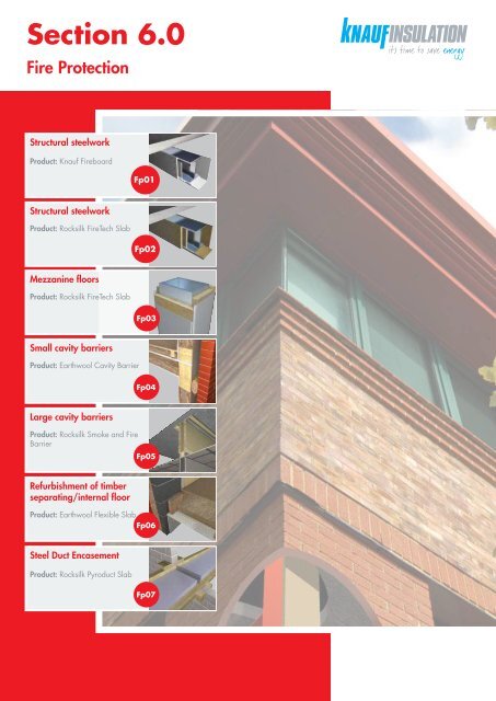
Section 6.0<br />
<strong>Fire</strong> <strong>Protection</strong><br />
Structural steelwork<br />
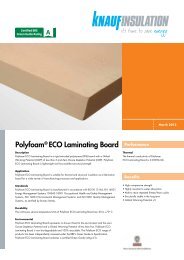
Product: <strong>Knauf</strong> <strong>Fire</strong>board<br />
Fp01<br />
Structural steelwork<br />
Product: Rocksilk <strong>Fire</strong>Tech Slab<br />
Fp02<br />
Mezzanine floors<br />
Product: Rocksilk <strong>Fire</strong>Tech Slab<br />
Fp03<br />
Small cavity barriers<br />
Product: Earthwool Cavity Barrier<br />
Fp04<br />
Large cavity barriers<br />
Product: Rocksilk Smoke and <strong>Fire</strong><br />
Barrier<br />
Fp05<br />
Refurbishment of timber<br />
separating/internal floor<br />
Product: Earthwool Flexible Slab<br />
Fp06<br />
Steel Duct Encasement<br />
Product: Rocksilk Pyroduct Slab<br />
Fp07
6.1<br />
<strong>Fire</strong> <strong>Protection</strong><br />
<strong>Fire</strong> protection of structural steel<br />
<strong>Fire</strong> protection design<br />
<strong>Knauf</strong> <strong>Insulation</strong> are members of<br />
the Association for Specialist <strong>Fire</strong><br />
<strong>Protection</strong>, and our fire protection<br />
products are listed in the Yellow<br />
Book, which presents economical<br />
methods for the fire protection of<br />
structural steelwork to provide<br />
compliance with Building<br />
Regulations<br />
266<br />
Structural steel requires fire protection because<br />
it loses structural strength at temperatures that<br />
can be rapidly reached in a building fire. This<br />
will consequently have a negative impact on the<br />
structural integrity of the building. Protecting the<br />
structural steel from the heat of a fire will delay<br />
the onset of this loss of strength and the possible<br />
collapse of the building. This is essential<br />
because it allows extra time for both the<br />
occupants of the building to escape and fire<br />
services to tackle the fire. It could also prevent<br />
the actual collapse of the building minimising<br />
insurance losses. Building Regulations covering<br />
fire safety are concerned with the preservation<br />
of life.<br />
With the increasing use of structural steel in<br />
construction, designers need fire protection<br />
solutions that provide a combination of fast<br />
installation and cost-effectiveness whilst<br />
achieving the desired finish.<br />
Whatever the application <strong>Knauf</strong> <strong>Insulation</strong> has<br />
a range of board products and systems to cater<br />
for any project.<br />
When used for the fire protection of structural<br />
steelwork, board systems offer several<br />
compelling advantages over site applied paint<br />
and spray coating systems.<br />
Board systems:<br />
• Are manufactured to factory tolerances – this<br />
enables the specifier to be certain that the<br />
correct thickness of fire protection is being<br />
applied, by simply checking the thickness of<br />
materials supplied<br />
Technical Advice and Support Centre 01744 766666<br />
• Can be installed prior to the building being<br />
sealed and made watertight, in all<br />
temperature and humidity conditions – this<br />
is in contrast to paint and sprays which are<br />
often restricted by normal UK winter<br />
conditions, causing potential delay to<br />
site programs<br />
• Are fast, clean, and dry to install, with<br />
negligible dust levels, allowing other trades<br />
to work in close proximity<br />
• Are quick and easy to check (by visual<br />
inspection) that all relevant areas have<br />
been protected<br />
• Are fully compatible with drylining systems<br />
and allow easy integration with partitioning<br />
schemes<br />
<strong>Fire</strong> protection<br />
Any steel section which is an element of<br />
structure and is deemed by any of the following<br />
regulations to require fire resistance can be<br />
protected with a fire protection system of dense<br />
rock mineral wool slabs or fibre reinforced<br />
gypsum based boards.<br />
1. The Building Regulations (England and<br />
Wales) Approved Document B (<strong>Fire</strong> Safety) –<br />
Volumes 1 and 2 (2006)<br />
2. The Building (Scotland) Regulations,<br />
Technical Booklets, Section 2, 2011<br />
3. The Building Regulations (Northern Ireland)<br />
Technical Booklet E, 2005<br />
4. The Building Regulations (Republic of Ireland)<br />
Technical Guidance Document B (2006)<br />
www.knaufinsulation.co.uk<br />
5. Loss Prevention Council Code of Practice for<br />
Construction of Buildings<br />
Steel sections can include universal beams,<br />
columns and joists (plain and castellated),<br />
structural and rolled tees, angles, channels and<br />
round, square or rectangular hollow sections.<br />
Benefits<br />
Both rock mineral wool slabs and fibre<br />
reinforced gypsum boards offer a number of<br />
advantages for the fire protection of structural<br />
steelwork that make them ideal for fast track<br />
projects.<br />
Rock mineral wool<br />
• Lightweight product – at less than half the<br />
weight of calcium silicate slabs – rock<br />
mineral wool fire protection boards are easy<br />
to handle and fit on site particularly for<br />
overhead work<br />
• Ease of cutting and fixing: Rock mineral wool<br />
slabs are easy to cut with either a saw or a<br />
sharp knife, furthermore there are four fixing<br />
methods, all involve square edge butt joints<br />
between the boards which enables a fast and<br />
simple system to be installed without delaying<br />
other trades and activities<br />
Fibre reinforced gypsum<br />
• Smooth surface – only requires decorative<br />
finishes for completion<br />
• Robust and impact resistant – ideal for<br />
columns and all exposed surfaces<br />
• Easy to cut to size – can be scored and<br />
snapped to speed up cutting and reduce<br />
dust levels
<strong>Fire</strong> <strong>Protection</strong> 6.1<br />
<strong>Fire</strong> protection<br />
Solution optimiser and pathfinder<br />
Key<br />
Pb01<br />
Find online. Visit knaufinsulation.co.uk and key in construction code to find the<br />
most up to date information on your chosen solution.<br />
<strong>Fire</strong> protection<br />
Period of fire resistance (mins)<br />
<strong>Knauf</strong> <strong>Insulation</strong> solution<br />
0 mins 30 mins 60 mins 90 mins 120 mins 150 mins 180 mins 210 mins 240 mins<br />
Structural steelwork<br />
Product: <strong>Knauf</strong> <strong>Fire</strong>board<br />
See page: 268<br />
Fp01<br />
Structural steelwork<br />
Product: Rocksilk <strong>Fire</strong>Tech Slab<br />
See page: 274<br />
Fp02<br />
Mezzanine floors<br />
Product: Rocksilk <strong>Fire</strong>Tech Slab<br />
See page: 280<br />
Fp03<br />
Fp04<br />
Large cavity barriers<br />
Product: Rocksilk Smoke and <strong>Fire</strong> Barrier<br />
6.1<br />
See page: 286<br />
Fp05<br />
Refurbishment of timber separating/<br />
internal floor<br />
Product: Earthwool Flexible Slab<br />
See page: 292<br />
Fp06<br />
Steel Duct Encasement<br />
Product: Rocksilk Pyroduct Slab<br />
See page: 294<br />
Fp07<br />
Technical Advice and Support Centre 01744 766666<br />
www.knaufinsulation.co.uk<br />
267
6.1<br />
<strong>Fire</strong> <strong>Protection</strong><br />
<strong>Fire</strong> protection<br />
Structural steelwork<br />
<strong>Knauf</strong> <strong>Fire</strong>board<br />
• Quick and easy to install<br />
Fp01<br />
NEW BUILD<br />
REFURB<br />
• Dry fix system providing up to 2<br />
hours fire protection<br />
• Combined fire protection and<br />
aesthetic finish<br />
<strong>Knauf</strong> Drywall Screws at maximum<br />
100mm centres into backing strips<br />
<strong>Knauf</strong> <strong>Fire</strong>board<br />
<strong>Knauf</strong> <strong>Fire</strong>board<br />
• Non-combustible with a Euroclass<br />
A1 reaction to fire rating<br />
• Zero Ozone Depletion Potential (ODP)<br />
• Zero Global Warming Potential (GWP)<br />
Abutment angles: light gauge<br />
steel angle provides support at<br />
soffit and wall junctions. Fixed to<br />
adjoining soffit or section flange.<br />
Edge fix the boards using<br />
either <strong>Knauf</strong> Drywall Screws<br />
at maximum 150mm centres<br />
or proprietary staples at<br />
120mm centres.<br />
Products<br />
<strong>Knauf</strong> <strong>Fire</strong>board is a gypsum based board<br />
specially developed for high performance lining<br />
and encasement, providing up to two hours of<br />
fire protection.<br />
<strong>Knauf</strong> <strong>Fire</strong>board has a high quality white<br />
smooth surface finish ideally suited as a self<br />
finish. Its surface allows direct decoration with<br />
most paint finishes or it can be plastered*.<br />
<strong>Knauf</strong> Drywall Screws are gold passivated<br />
screws with spoon tips and ‘hi-low’ threads.<br />
<strong>Knauf</strong> <strong>Fire</strong>board can also be installed using<br />
proprietary staples.<br />
*Consult plaster manufacturer prior to application of plaster<br />
finish.<br />
Typical construction<br />
<strong>Knauf</strong> <strong>Fire</strong>board is used in frameless<br />
encasements. The product has been specially<br />
developed to accept direct edge fixings.<br />
Casings consist of <strong>Knauf</strong> <strong>Fire</strong>board screwed or<br />
stapled to itself at abutting corners.<br />
For steelwork encased on all four sides, <strong>Knauf</strong><br />
<strong>Fire</strong>board is fixed at each corner directly<br />
through the material, independent of the column<br />
or beam. For partial encasement, involving wall<br />
or ceiling abutments, <strong>Knauf</strong> <strong>Fire</strong>board is fixed to<br />
light gauge steel angles.<br />
<strong>Knauf</strong> <strong>Insulation</strong> recommend the use of <strong>Knauf</strong><br />
Drywall Screws, essential for fast construction,<br />
solid fixing and tightly closed edge joints.<br />
268<br />
Technical Advice and Support Centre 01744 766666<br />
www.knaufinsulation.co.uk
<strong>Fire</strong> <strong>Protection</strong> 6.1<br />
Typical specification<br />
<strong>Knauf</strong> <strong>Fire</strong>board, ...…mm thick, to be used to<br />
provide fire protection to structural steelwork.<br />
Stagger joints by 300mm minimum<br />
<strong>Knauf</strong> <strong>Fire</strong>board casing<br />
It is to be installed on beam*/column* as a<br />
complete 4 sided*/3 sided*/2 sided*<br />
encasement (*specifier’s choice) to provide<br />
......minutes fire protection as detailed in the<br />
Installation section.<br />
Alternatively, consult the National<br />
Building Specifications, Standard<br />
version clause/clauses…<br />
K10/265……………<br />
<strong>Knauf</strong> <strong>Insulation</strong> specification clauses can be<br />
downloaded from knaufinsulation.co.uk/nbs<br />
Direct edge-fixing with <strong>Knauf</strong> Drywall<br />
Screws at 200mm centres or<br />
proprietary staples at 120mm centres<br />
Performance<br />
<strong>Fire</strong> performance<br />
The system can provide up to 2 hours fire<br />
protection. For precise calculation of fire<br />
protection periods, please contact <strong>Knauf</strong><br />
<strong>Insulation</strong> Technical Advice and Support Centre.<br />
Operating temperatures<br />
Continuous long term exposure to temperatures<br />
over 50ºC can induce a change of state which<br />
would reduce the physical performance and<br />
serviceability of the boards.<br />
<strong>Knauf</strong> <strong>Fire</strong>board is non-combustible<br />
to BS 476: Part 4: 1970 (1984) and Class 1<br />
surface spread of flame to BS 476: Part 7:<br />
1997. <strong>Knauf</strong> <strong>Fire</strong>board complies with the Class<br />
‘0’ requirements of the Building Regulations<br />
when tested to BS 476: Part 6: 1989 and Part<br />
7: 1997 and with the limited combustibility<br />
described in the Building Regulations.<br />
Health and safety<br />
<strong>Knauf</strong> <strong>Fire</strong>board must be installed with care.<br />
Ensure adequate ventilation during installation,<br />
particularly when cutting boards. Avoid harsh<br />
body contact with sharp cut edges of metal<br />
components. Refer to <strong>Knauf</strong> <strong>Insulation</strong> Material<br />
Safety Data Sheets and to the Health and Safety<br />
Executive publications.<br />
6.1<br />
Humidity<br />
Constant humidity over 95% or subjection to<br />
continuous water will reduce the serviceability<br />
of the boards.<br />
For Hp/A tables please visit<br />
knaufinsulation.co.uk<br />
Technical Advice and Support Centre 01744 766666<br />
www.knaufinsulation.co.uk<br />
269
6.1<br />
<strong>Fire</strong> <strong>Protection</strong><br />
<strong>Fire</strong> protection<br />
Installation of column system<br />
Installation sequence<br />
Cut two boards to<br />
1 the width of the 2<br />
column flange.<br />
Hold in place the<br />
first 2 boards<br />
with clamps.<br />
3<br />
After measuring the<br />
size of the remaining<br />
2 sides, cut another<br />
two to the depth of<br />
the column plus<br />
twice the thickness<br />
of the board.<br />
4<br />
Apply the remaining<br />
boards, adjusting<br />
the length of<br />
adjoining boards to<br />
ensure that board<br />
joints are staggered<br />
by at least 300mm.<br />
5<br />
Edge-fix the boards<br />
using either self<br />
drilling <strong>Knauf</strong><br />
<strong>Fire</strong>board Gripper<br />
Screws at 200mm<br />
centres or proprietary<br />
staples at 120mm<br />
centres. <strong>Knauf</strong><br />
<strong>Fire</strong>board Gripper<br />
Screws should<br />
penetrate into the<br />
casing by at least<br />
30mm<br />
Installation<br />
Steelwork encasements must be installed in full<br />
accordance with <strong>Knauf</strong> <strong>Insulation</strong>’s<br />
recommendations and in compliance with<br />
BS 8212: 1995 and BS 8000: Part 8: 1994.<br />
The installation procedures outlined here relate<br />
to normal single layer applications.<br />
<strong>Knauf</strong> Drywall Screws<br />
<strong>Knauf</strong> Drywall Screws should penetrate into the<br />
casing by at least 30mm.<br />
Four-sided column encasement<br />
• Cut two boards to the width of the column<br />
flange. Cut another two to the depth of the<br />
column plus twice the thickness of the board<br />
• Adjust the length of adjoining boards to<br />
ensure that board joints are staggered by at<br />
least 300mm<br />
• Edge-fix the boards using either <strong>Knauf</strong><br />
Drywall Screws at 200mm centres or<br />
proprietary staples at 120mm centres<br />
Partial column encasement<br />
Assuming a typical three-sided encasement<br />
where one of the column flanges straddles a<br />
wall, follow the same procedure as outlined<br />
for four-sided encasement with the following<br />
differences:<br />
• Fix 25 x 25mm light gauge steel angles,<br />
in continuous lengths, to either the abutting<br />
wall face or the inner flange of the column.<br />
Use appropriate proprietary fixings at<br />
600mm centres<br />
Double layer application<br />
Install the first layer as described for either full<br />
or partial encasement. Secure the second layer<br />
to the first with fixings spaced as for the first<br />
layer but avoid coincident fixing positions.<br />
It is good practice that board joints are<br />
staggered – as with the first layer – between<br />
adjoining boards and also between the two<br />
layers. In the case of structural steelwork,<br />
double layer encasement will obviate the need<br />
for joint backing strips.<br />
270<br />
Technical Advice and Support Centre 01744 766666<br />
www.knaufinsulation.co.uk
<strong>Fire</strong> <strong>Protection</strong> 6.1<br />
<strong>Fire</strong> protection<br />
Installation of beam system<br />
Installation sequence<br />
1<br />
Install continuous lengths of<br />
25 x 25mm angle using<br />
appropriate proprietary<br />
2<br />
Cut two boards to the depth<br />
of the section plus twice the<br />
board thickness plus l0mm.<br />
3<br />
Cut a soffit board to the<br />
width of the steel flange.<br />
The length of this board must<br />
4<br />
Cut board off-cuts 100mm<br />
wide as joint backing strips.<br />
Fit these, half lapped, behind<br />
fixings at 600mm centres, fix<br />
further lengths of 25 x 25mm<br />
angle at any end abutment.<br />
Screw-fix these to the angles<br />
at 150mm centres with<br />
35mm <strong>Knauf</strong> Drywall<br />
Screws.<br />
differ from the side boards to<br />
ensure adjacent board joints<br />
are staggered by at least<br />
300mm.<br />
all butt joints at the sides<br />
and soffit of the beam.<br />
Fix with <strong>Knauf</strong> <strong>Fire</strong>board<br />
Gripper Screws at maximum<br />
Edge-fix horizontal board to<br />
100mm centres.<br />
the two vertical boards using<br />
either <strong>Knauf</strong> <strong>Fire</strong>board<br />
Gripper Screws at 150mm<br />
centres or proprietary staples<br />
at 120mm centres.<br />
Beam encasement<br />
Assuming a typical three-sided encasement,<br />
where a beam is exposed directly below a level<br />
soffit, fix light gauge steel angles to either the<br />
adjoining soffit or the top flange of the beam.<br />
Install continuous lengths of 25 x 25mm angle<br />
using appropriate proprietary fixings at 600mm<br />
centres.<br />
• Cut board off-cuts 100mm wide as joint<br />
backing strips. Fit these, half-lapped, behind<br />
all butt joints at the sides and soffit of the<br />
beam fixed with <strong>Knauf</strong> Drywall Screws at<br />
maximum 100mm centres<br />
Double layer application<br />
Install the first layer as described for either full<br />
nominal 150mm centres, screw lengths should<br />
be equal to the thickness of the second layer,<br />
plus 30mm. Where two different thicknesses of<br />
<strong>Fire</strong>board are applied, the thicker layer is<br />
installed first.<br />
6.1<br />
• Fix further lengths of 25 x 25mm angle at any<br />
or partial encasement. Secure the second layer<br />
end abutment<br />
to the first with fixings spaced as for the first<br />
• Cut two boards to the depth of the section<br />
layer but avoid coinciding fixing positions.<br />
plus twice the thickness of the board plus<br />
It is good practice that board joints are<br />
l0mm. Screw-fix these to the angles at<br />
staggered – as with the first layer – between<br />
150mm centres with 35mm <strong>Knauf</strong> Drywall<br />
adjoining boards and also between the two<br />
Screws<br />
layers. In the case of structural steelwork,<br />
• Cut a soffit board to the width of the steel<br />
flange. The length of this board must differ<br />
from the side boards to ensure adjacent<br />
board joints are staggered by at least<br />
300mm. Edge-fix this horizontal board to the<br />
two vertical boards using either self-drilling<br />
<strong>Knauf</strong> Drywall Screws at 150mm centres or<br />
double layer encasement will obviate the need<br />
for joint backing strips.<br />
The second layer of boards across the webs are<br />
fixed to the angle attached to the upper flange<br />
using 55mm long <strong>Knauf</strong> Drywall Screws at<br />
150mm centres and the second layer across the<br />
bottom flange using <strong>Knauf</strong> Drywall Screws at<br />
staples at 120mm centres<br />
Technical Advice and Support Centre 01744 766666<br />
www.knaufinsulation.co.uk<br />
271
6.1<br />
<strong>Fire</strong> <strong>Protection</strong><br />
<strong>Fire</strong> protection<br />
Application details for beams<br />
Beam with partition abutment<br />
25 x 25mm angle secured to top flange<br />
of beam, or alternatively to soffit<br />
<strong>Knauf</strong> Drywall Screws at maximum<br />
100mm centres<br />
<strong>Fire</strong>board casing<br />
Backing strip<br />
10mm gap<br />
Direct edge fixing with <strong>Knauf</strong> Drywall<br />
Screws at maximum 150mm centres or<br />
staples at 120mm centres<br />
C-Stud partition with standard<br />
U-Channel head track<br />
Beam with wall abutment<br />
25 x 25mm angle secured to top flange of<br />
beam, or alternatively to soffit<br />
<strong>Knauf</strong> Drywall Screws at maximum<br />
100mm centres<br />
<strong>Fire</strong>board casing<br />
Direct edge fixing with <strong>Knauf</strong><br />
<strong>Fire</strong>board Gripper Screws at<br />
maximum 150mm centres or<br />
staples at 120mm centres<br />
Continuous 25 x 25mm <strong>Knauf</strong><br />
<strong>Fire</strong>board Angle secured to substrate<br />
using appropriate fixings<br />
Masonry wall<br />
272<br />
Technical Advice and Support Centre 01744 766666<br />
www.knaufinsulation.co.uk
<strong>Fire</strong> <strong>Protection</strong> 6.1<br />
Column with partition abutment<br />
Direct edge fixing with <strong>Knauf</strong> Drywall<br />
Screws at maximum 200mm centres or<br />
staples at 120mm centres<br />
<strong>Knauf</strong> C-Stud toggle-fixed to <strong>Knauf</strong><br />
<strong>Fire</strong>board casing<br />
<strong>Knauf</strong> Wallboard not fixed to this C-Stud<br />
Column with wall lining abutment<br />
Continuous 25 x 25mm <strong>Knauf</strong><br />
<strong>Fire</strong>board angle at each corner<br />
<strong>Knauf</strong> Wallboard not fixed to this C-Stud<br />
6.1<br />
Direct edge fixing with <strong>Knauf</strong> Drywall<br />
Screws at maximum 200mm centres or<br />
staples at 120mm centres<br />
Technical Advice and Support Centre 01744 766666<br />
www.knaufinsulation.co.uk<br />
273
6.1<br />
<strong>Fire</strong> <strong>Protection</strong><br />
<strong>Fire</strong> protection<br />
Structural steelwork<br />
Rocksilk <strong>Fire</strong>Tech Slab<br />
• Flexible system with four installation<br />
methods<br />
• Maintenance free, passive system<br />
• Clean installation process with<br />
negligible dust generation<br />
Fp02<br />
Rocksilk <strong>Fire</strong>Tech Slab<br />
REFURB<br />
Rocksilk <strong>Fire</strong>Tech Slab<br />
• Non-combustible with a Euroclass A1<br />
reaction to fire rating<br />
• Zero Ozone Depletion Potential (ODP)<br />
• Zero Global Warming Potential (GWP)<br />
Pig tail screws<br />
Noggin of Rocksilk <strong>Fire</strong>Tech Slab<br />
or Rocksilk <strong>Fire</strong>Tech Dry Fix Noggin<br />
Slab<br />
Product<br />
Rocksilk <strong>Fire</strong>Tech Slab is a dense rock mineral<br />
wool slab. It is available unfaced or faced with<br />
a bright Class ‘0’ reinforced aluminium foil, for<br />
applications above clean rooms, within air<br />
plenums, or for aesthetic purposes.<br />
Plaster manufacturers advice and guidance<br />
should be followed regarding pre-treatment of<br />
Rocksilk <strong>Fire</strong>Tech Slabs before application of<br />
plaster finishes<br />
Rocksilk <strong>Fire</strong>Tech Dry Fix Noggin Slab is an ultra<br />
high density rock mineral wool slab used for the<br />
noggin in the Rocksilk <strong>Fire</strong>Tech Dry Fix Noggin<br />
System.<br />
Typical construction<br />
The exposed surfaces of any steel section are<br />
fully enclosed in Rocksilk <strong>Fire</strong>Tech Slab, using<br />
any of the fixing systems shown on the following<br />
pages.<br />
Rocksilk <strong>Fire</strong>Tech Slab can be used to provide<br />
up to 4 hours fire protection to structural steel<br />
and cast iron columns, beams and trusses. Steel<br />
sections may include universal beams, columns<br />
and joists (plain and castellated), structural and<br />
rolled tees, angles, channels and round, square<br />
or rectangular hollow sections.<br />
Installation<br />
Rocksilk <strong>Fire</strong>Tech Slab can be used with four<br />
types of fixing methods for the fire protection of<br />
structural steelwork and each system has its own<br />
performance characteristics.<br />
Fixing methods:<br />
• Dry Fix Noggin System<br />
• Adhesive Noggin Fixing System<br />
• Combination Fixing System<br />
• Welded Pin Fixing System<br />
274<br />
Technical Advice and Support Centre 01744 766666<br />
www.knaufinsulation.co.uk
<strong>Fire</strong> <strong>Protection</strong> 6.1<br />
Technical specification<br />
Rocksilk <strong>Fire</strong>Tech Slab, ...…mm thick, to be<br />
used to provide fire protection to structural<br />
steelwork.<br />
Noggin of Rocksilk <strong>Fire</strong>Tech Slab or<br />
Rocksilk <strong>Fire</strong>Tech Dry Fix Noggin<br />
Slab<br />
Pig Tail Screws<br />
It is to be installed using the dry fix noggin<br />
system*/adhesive noggin fixing system*/<br />
combination fixing system*/welded pin<br />
fixing system* (*specifier’s choice) as<br />
detailed in the Installation section.<br />
Alternatively, consult the National<br />
Building Specifications, Standard<br />
version clause/clauses…<br />
K11/885……………<br />
<strong>Knauf</strong> <strong>Insulation</strong> specification clauses can be<br />
downloaded from knaufinsulation.co.uk/nbs<br />
Rocksilk <strong>Fire</strong>Tech Slab<br />
Performance<br />
<strong>Fire</strong> performance<br />
Rocksilk <strong>Fire</strong>Tech Slab is classified as<br />
non-combustible to BS 476: Part 4:<br />
1970(1984), Class 1 surface spread of flame<br />
to BS 476: Part 7: 1997, and Class ‘0’ to the<br />
Building Regulations. Rocksilk <strong>Fire</strong>Tech Slab is<br />
designed to provide up to 4 hours fire<br />
protection to structural steelwork, thereby<br />
satisfying the Building Regulations and<br />
insurance demands for periods of fire<br />
resistance.<br />
Durability<br />
Rocksilk <strong>Fire</strong>Tech Slab is rot proof, does not<br />
sustain vermin and will not encourage the<br />
growth of fungi, mould or bacteria.<br />
Rocksilk <strong>Fire</strong>Tech Slab is odourless and<br />
non-hygroscopic.<br />
Rocksilk <strong>Fire</strong>Tech Slab is non-wicking when<br />
tested to BS 2972: 1989: Section 12.<br />
When exposed to 90% relative humidity and<br />
20ºC, Rocksilk <strong>Fire</strong>Tech Slab absorbs less than<br />
0.004% of moisture.<br />
6.1<br />
For Hp/A tables please visit<br />
knaufinsulation.co.uk<br />
Technical Advice and Support Centre 01744 766666<br />
www.knaufinsulation.co.uk<br />
275
6.1<br />
<strong>Fire</strong> <strong>Protection</strong><br />
<strong>Fire</strong> protection<br />
Installation of Rocksilk <strong>Fire</strong>Tech Slab<br />
Dry Fix Noggin System<br />
Up to 2 hours fire protection<br />
Adhesive Noggin Fixing System<br />
Up to 2 hours fire protection<br />
100mm wide noggins of<br />
Rocksilk <strong>Fire</strong>Tech Dry Fix<br />
Noggin Slab friction fitted<br />
between the flanges.<br />
Attach web pieces to<br />
noggins with pig tail<br />
screws at 100mm centres.<br />
Attach flange pieces to web<br />
pieces using pig tail screws<br />
positioned 25mm in from<br />
each end and at 150mm<br />
centres.<br />
Attach web pieces to noggins<br />
with pig tail screws at<br />
100mm centres.<br />
100mm wide noggin of<br />
Rocksilk <strong>Fire</strong>Tech Slab<br />
glued into place using<br />
suitable adhesive<br />
Attach flange pieces to<br />
web pieces using pig tail<br />
screws positioned 25mm<br />
in from each end and at<br />
150mm centres.<br />
Combination Fixing System<br />
Up to 3 hours fire protection<br />
Welded Pin Fixing System<br />
Up to 4 hours fire protection<br />
Attach the Rocksilk <strong>Fire</strong>Tech<br />
Slab web pieces by impaling<br />
over the welded pins and<br />
securing in place with 38mm<br />
spring steel washers.<br />
Attach flange pieces to web<br />
pieces using pig tail screws<br />
at 150mm centres.<br />
Adhesive should be used at<br />
the joint between subsequent<br />
web pieces.<br />
Attach the Rocksilk <strong>Fire</strong>Tech<br />
Slab web and flange pieces<br />
by impaling over the 3mm<br />
diameter welded mild steel<br />
pins and securing in place<br />
with 38mm spring steel<br />
washers.<br />
Adhesive should be used at<br />
the joint between subsequent<br />
web pieces.<br />
Alternative installation methods<br />
The Dry Fix Noggin System<br />
Is a fast and efficient friction fit noggin system<br />
that does not require adhesive. It can give up to<br />
2 hours fire protection to BS 476: Part 21.<br />
When installing 20, 25 and 30mm Rocksilk<br />
<strong>Fire</strong>Tech Slab, noggins should be cut from a<br />
30mm Rocksilk <strong>Fire</strong>Tech Dry Fix Noggin Slab.<br />
When greater thicknesses of Rocksilk <strong>Fire</strong>Tech<br />
Slab are used, the noggins are cut from a<br />
corresponding thickness of Rocksilk <strong>Fire</strong>Tech Dry<br />
Fix Noggin Slab.<br />
The Adhesive Noggin Fixing System<br />
Can be used to provide up to 2 hours fire<br />
protection to all sizes of structural steelwork.<br />
The Combination Fixing System<br />
Can be used to provide up to 2 hours fire<br />
protection to all sizes of structural steelwork,<br />
and up to 3 hours fire protection to steelwork<br />
with section factors (Hp/A) of up to 133m -1 for<br />
columns and 143m -1 for beams.<br />
The Welded Pin Fixing System<br />
Can be used to provide up to 3 hours fire<br />
protection to all sizes of structural steelwork,<br />
and up to 4 hours fire protection to steelwork<br />
with section factors (Hp/A) of up to 172m -1 for<br />
columns and 184m -1 for beams.<br />
If section factors are above 260m -1 contact our<br />
Technical Advice and Support Centre.<br />
The use of a dense rock mineral wool slab<br />
requires no special vee cuts, drilling or<br />
sub-frames, making it fast and easy to install.<br />
Rock mineral wool slabs can be easily cut using<br />
hand or power tools.<br />
Note: Rocksilk <strong>Fire</strong>Tech Dry Fix Noggin Slab has a density<br />
of 200 kg/m 3 .<br />
276<br />
Technical Advice and Support Centre 01744 766666<br />
www.knaufinsulation.co.uk
<strong>Fire</strong> <strong>Protection</strong> 6.1<br />
Greater<br />
than<br />
500mm<br />
Full<br />
depth<br />
Greater<br />
than<br />
500mm<br />
Y<br />
100mm<br />
100mm<br />
X<br />
Solid noggin formed from one or more pieces<br />
of Rocksilk <strong>Fire</strong>Tech Slab<br />
T-shaped noggin formed from two pieces of<br />
Rocksilk <strong>Fire</strong>Tech Slab joined at right angles<br />
using pig tail screws<br />
Insert noggins as described at 600mm<br />
centres and if practicable leave for 4 hours<br />
for adhesive to cure.<br />
Cut Rocksilk <strong>Fire</strong>Tech Slab to size as follows:<br />
Beams: flange pieces to dimension X, web<br />
pieces to dimension Y + t (t = thickness of<br />
board)<br />
Columns: flange pieces to dimension X,<br />
web pieces to dimension Y + 2t<br />
Attach web pieces to noggins using pig tail<br />
screws at 100mm centres<br />
Attach flange pieces to web pieces using pig<br />
tail screws positioned 25mm in from each<br />
end at 150mm centres.<br />
Note: For flanges greater than 400mm use welded pin<br />
and spring steel washers to provide extra retention of<br />
the flange piece of insulation. The welded pins should<br />
be located along the centre line of the flange at 300mm<br />
centres.<br />
Adhesive noggin fixing system<br />
Noggins are cut 100mm wide from 20mm thick<br />
Rocksilk <strong>Fire</strong>Tech Slab. They should be cut to a<br />
suitable length relative to the web size to give<br />
a tight compression fit.<br />
Noggins are glued top and bottom using a<br />
typical adhesive thickness of 0.5mm and friction<br />
fitted between the flanges at 600mm centres.<br />
The noggins should be installed in such a way<br />
that they are slightly 'proud' of the flange (by<br />
about 2mm) and such that they coincide with<br />
joints between the boards.<br />
It is preferable to leave the noggins in position<br />
for 4 hours to allow the adhesive to cure.<br />
However, where this is impractical Rocksilk<br />
<strong>Fire</strong>Tech Slab can still be fitted before the<br />
adhesive cures since the noggins are essentially<br />
friction fitted.<br />
For web depths greater than 500mm, T-shaped<br />
or solid noggins should be used, formed from<br />
Rocksilk <strong>Fire</strong>Tech Slab, and screwed together<br />
using pig tail screws.<br />
6.1<br />
Technical Advice and Support Centre 01744 766666<br />
www.knaufinsulation.co.uk<br />
277
6.1<br />
<strong>Fire</strong> <strong>Protection</strong><br />
<strong>Fire</strong> protection<br />
Application details for beams<br />
Partition abutment using a noggin fixing system<br />
Pig tail screws at maximum<br />
100mm centres<br />
Rocksilk <strong>Fire</strong>Tech noggin<br />
Rocksilk <strong>Fire</strong>Tech Slab<br />
Direct edge fixing with pig tail screws at<br />
maximum 150mm centres<br />
Attach flange piece to web piece by<br />
impaling over welded pins and securing<br />
the board to board joint with pig tail<br />
screws at 150mm centres. Spring steel<br />
washers are used over the welded pins to<br />
retain the insulation, any excess pin<br />
length being trimmed off<br />
C-Stud partition with standard U-Channel<br />
head track<br />
Wall abutment using a noggin fixing system<br />
Pigtail screws at maximum 100mm centres<br />
Masonry wall<br />
Rocksilk <strong>Fire</strong>Tech Slab<br />
Direct edge fixing with pig tail screws at<br />
maximum 150mm centres<br />
Attach flange piece to web piece by impaling<br />
over welded pins and securing the board to<br />
board joint with pig tail screws at 150mm<br />
centres. Spring steel washers are used over<br />
the welded pins to retain the insulation, any<br />
excess pin length being trimmed off<br />
278<br />
Technical Advice and Support Centre 01744 766666<br />
www.knaufinsulation.co.uk
<strong>Fire</strong> <strong>Protection</strong> 6.1<br />
Adhesive detail<br />
The adhesive used for gluing Rocksilk <strong>Fire</strong>Tech<br />
Slabs should be a thixotropic paste type based<br />
on soluble solids of silicate and potassium<br />
mixed with clay or refractory mineral filler to an<br />
approximate ratio of 70:30 by weight.<br />
Steelwork should ideally be dry but the<br />
presence of condensation will merely prolong<br />
the cure time, not weaken the bond strength.<br />
Since only the top and bottom surface of each<br />
noggin is glued with a typical adhesive<br />
thickness of 0.5mm, excellent rates of usage are<br />
achievable.<br />
Note: Steelwork should be clean and free from grease prior<br />
to the application of adhesive.<br />
*For further details contact our Technical Advice and<br />
Support Centre.<br />
Pig tail screws<br />
The spirally wound or pig tail screws are<br />
made from 16 gauge galvanised wire and<br />
are available from stockists. A specification<br />
is available on request from our Technical<br />
Advice and Support Centre.<br />
The screws should be installed flush at 150mm<br />
centres on board to board joints and 100mm<br />
centres over noggins, using either power or<br />
hand tools. There is no need to countersink the<br />
screw heads.<br />
Column with partition abutment<br />
Rocksilk <strong>Fire</strong>Tech Slab<br />
<strong>Knauf</strong> Wallboard not fixed to this C-Stud<br />
Direct edge fixing with pig tail screws at<br />
maximum 150mm centres<br />
Column with wall lining abutment<br />
6.1<br />
Masonry wall<br />
<strong>Knauf</strong> Wallboard not fixed to this C-Stud<br />
Rocksilk <strong>Fire</strong>Tech Slab<br />
Direct edge fixing with pig tail screws at<br />
maximum 150mm centres<br />
Technical Advice and Support Centre 01744 766666<br />
www.knaufinsulation.co.uk<br />
279
6.1<br />
<strong>Fire</strong> <strong>Protection</strong><br />
<strong>Fire</strong> protection<br />
Mezzanine floors<br />
Rocksilk <strong>Fire</strong>Tech Slab<br />
• Simple, clean and quick to install<br />
• Provides up to 3 hours fire resistance<br />
• System covers section factors up to<br />
310 Hp/A - (A/V)<br />
Fp03<br />
REFURB<br />
Rocksilk <strong>Fire</strong>Tech Slab<br />
• Non-combustible with a Euroclass A1<br />
reaction to fire rating<br />
• Zero Ozone Depletion Potential (ODP)<br />
• Zero Global Warming Potential (GWP)<br />
Rocksilk <strong>Fire</strong>Tech Slab<br />
Product<br />
Rocksilk <strong>Fire</strong>Tech Slab is a dense rock mineral<br />
wool slab specifically designed for the fire<br />
protection of structural steelwork.<br />
Typical construction<br />
The exposed surface of a steel section is fully<br />
enclosed in Rocksilk <strong>Fire</strong>Tech Slab, using a<br />
metal clip, snap-lock system.<br />
Installation<br />
The column case is pre-fabricated to suit the<br />
specific beam or column. It is lined with Rocksilk<br />
<strong>Fire</strong>tech Slab which is pre-bonded to the steel<br />
skin. Note that no adhesive is applied to the<br />
joints between individual slabs. The column<br />
case is made of galvanized or PVC coated steel<br />
minimum 0.7mm thick. For columns, the casing<br />
is normally supplied in two pieces with the<br />
closing face fixed with snap-lock joints.<br />
Three-sided encasements are secured at 300mm<br />
centres to continuous galvanized steel angles,<br />
or the flange of the steel section, or to the wall<br />
or floor at 500mm nominal centres.<br />
Alternatively the casing may be secured using<br />
an integral lip on the casing.<br />
Performance<br />
<strong>Fire</strong> performance<br />
Rocksilk <strong>Fire</strong>Tech Slab is classified as<br />
non-combustible to BS 476: Part 4: 1970<br />
(1984). Class 1 Surface Spread of Flame to BS<br />
476: Part 7:1977, and Class ‘O’ to the<br />
Building Regulations. Rocksilk <strong>Fire</strong>Tech Slab is<br />
designed to provide up to 3 hours fire<br />
protection to the mezzanine floor column<br />
support system, thereby satisfying the current<br />
Building Regulations and insurance industry fire<br />
resistance performance standards.<br />
Performance<br />
Rocksilk <strong>Fire</strong>Tech Slab is rot proof, does not<br />
sustain vermin, will not encourage the growth of<br />
fungi, mould or bacteria and is odourless and<br />
non-hygroscopic.<br />
280<br />
Technical Advice and Support Centre 01744 766666<br />
www.knaufinsulation.co.uk
<strong>Fire</strong> <strong>Protection</strong> 6.1<br />
Table 1 - Mezzanine floors<br />
Time - mins Board Thickness (mm) Hp/A<br />
60 20 224<br />
25 260<br />
30 310<br />
35 310<br />
40 310<br />
45 310<br />
90 20 91<br />
25 115<br />
Technical specification<br />
Rocksilk <strong>Fire</strong>Tech Slab….mm thick, to be<br />
used to provide fire protection to structural<br />
steelwork in a mezzanine floor system.<br />
Alternatively, consult the National<br />
Building Specifications, Standard<br />
version clause/clauses…<br />
K11/885…………<br />
<strong>Knauf</strong> <strong>Insulation</strong> specification clauses can be<br />
downloaded from knaufinsulation.co.uk/nbs<br />
30 139<br />
35 165<br />
40 190<br />
45 217<br />
50 244<br />
55 260<br />
60 270<br />
65 310<br />
120 20 57<br />
25 72<br />
30 87<br />
35 102<br />
40 117<br />
45 133<br />
50 149<br />
55 165<br />
60 181<br />
65 198<br />
180 30 49<br />
6.1<br />
35 58<br />
40 66<br />
45 75<br />
50 84<br />
55 92<br />
60 101<br />
65 110<br />
Technical Advice and Support Centre 01744 766666<br />
www.knaufinsulation.co.uk<br />
281
6.1<br />
<strong>Fire</strong> <strong>Protection</strong><br />
Cavity barriers<br />
Cavity barrier design<br />
Design considerations<br />
Every building must be designed and<br />
constructed in such a way that in the event of<br />
an outbreak of fire within the building, the<br />
unseen spread of fire and smoke within<br />
concealed cavities in its structure and fabric is<br />
inhibited. The Building Regulations require<br />
cavity barriers to sub-divide voids if they extend<br />
beyond certain dimensions.<br />
In addition cavity barriers are also required to<br />
be placed above fire resisting partitions. Both<br />
glass and rock mineral wool products are ideal<br />
to act as cavity barriers due to their inherent<br />
non-combustibility.<br />
In the case of fire stopping minor imperfections<br />
of fit between construction elements or<br />
components, it is acceptable to seal small gaps<br />
with unfaced glass or rock mineral wool<br />
products. However, for specific periods of fire<br />
resistance in small and large voids (as required<br />
by the Building Regulations) it is necessary to<br />
use specific products that have been tested and<br />
assessed to offer the required performance<br />
when installed in a specific way, if necessary,<br />
using specific fixing components.<br />
Concealed cavities<br />
<strong>Fire</strong> and smoke spread in concealed spaces is<br />
particularly hazardous because fire can spread<br />
quickly throughout a building and remain<br />
undetected by the occupants of the building.<br />
Cavity barriers are used to sub divide<br />
cavities and so prevent smoke and flame from<br />
by-passing fire-resisting walls and partitions.<br />
The maximum distance between barriers must<br />
be appropriate to the location of each cavity.<br />
Also, due consideration must be given to the<br />
class of surface exposed within the cavity.<br />
Cavity barriers should achieve at least 30<br />
minutes fire resistance, providing a minimum of<br />
30 minutes integrity and 15 minutes insulation.<br />
Detailed requirements are complex. For full<br />
details about the position and spacing of cavity<br />
fire barriers refer to the relevant sections of the<br />
appropriate Building Regulations.<br />
Small cavity barriers<br />
Small voids include the cavities in external walls<br />
and voids beneath raised access floors. Larger<br />
voids include the spaces between suspended<br />
ceilings and soffits or roofs.<br />
In cavities in external walls the resilient<br />
properties of glass mineral wool mean that it<br />
can be compression fitted, between the outer<br />
leaf and the inner leaf or frame. The noncombustible<br />
nature of glass mineral wool allows<br />
it to resist the effects of fire, enabling it to<br />
remain in place during the fire and effectively<br />
block the transfer of fire through the cavity.<br />
Large cavity barriers<br />
In England, Wales and Northern Ireland, all<br />
cavity barriers should be constructed to provide<br />
at least 30 minutes fire resistance and 15<br />
minutes insulation. In Scotland large cavity<br />
barriers, which are defined as being greater<br />
than 1m x 1m in size, must provide the same.<br />
Fixing systems<br />
Any product used for fire protection can only be<br />
considered to be offering a specific period of<br />
fire protection when it is installed in the manner<br />
specified in the appropriate fire test report. This<br />
includes the specification of all associated<br />
fixings and supporting frame work.<br />
282<br />
Technical Advice and Support Centre 01744 766666<br />
www.knaufinsulation.co.uk
<strong>Fire</strong> <strong>Protection</strong> 6.1<br />
Photograph courtesy of Henley Building Systems<br />
30 minutes fire resistance 1 hour fire resistance<br />
Definitions<br />
The following definitions are taken from<br />
Approved Document B (<strong>Fire</strong> safety) - Volume<br />
2: Buildings other than dwellinghouses<br />
(2006)<br />
50mm Rocksilk<br />
Smoke and <strong>Fire</strong><br />
Barrier<br />
Suspended ceiling<br />
of 12.5mm plasterboard<br />
50mm cavity<br />
50mm Rocksilk<br />
Smoke and<br />
<strong>Fire</strong> Barrier<br />
Cavity barrier<br />
A construction, other than smoke curtain,<br />
provided to close a concealed space against<br />
penetration of smoke or flame, or provided to<br />
restrict the movement of smoke or flame<br />
within such a space.<br />
<strong>Fire</strong> stop<br />
Seal provided to close an imperfection of<br />
fit or design tolerance between elements or<br />
components, to restrict the passage of fire<br />
or smoke. Any unfaced glass or rock mineral<br />
product can be used as a fire stop.<br />
Period of fire resistance (mins)<br />
6.1<br />
<strong>Knauf</strong> <strong>Insulation</strong> solution 0 mins 30 mins 60 mins 90 mins 120 mins 150 mins 180 mins 210 mins 240 mins<br />
Small cavity barriers - to be deleted<br />
Fp04<br />
Large cavity barriers<br />
Product: Rocksilk Smoke and <strong>Fire</strong> Barrier<br />
See page: 286<br />
Fp05<br />
Technical Advice and Support Centre 01744 766666<br />
www.knaufinsulation.co.uk<br />
283
6.1<br />
<strong>Fire</strong> <strong>Protection</strong><br />
<strong>Fire</strong> protection<br />
Small cavity barriers<br />
Earthwool Cavity Barrier<br />
• Meets Building Regulation<br />
requirements for fire, acoustics and<br />
party wall bypass applications<br />
• Simple, clean and quick to install<br />
• Colour coded for easy identification<br />
Fp04<br />
NEW BUILD<br />
Earthwool Cavity Barrier<br />
• Non-combustible with a Euroclass A1<br />
reaction to fire rating<br />
• A+ Generic BRE Green Guide rating<br />
• Zero Ozone Depletion Potential (ODP)<br />
• Zero Global Warming Potential (GWP)<br />
Earthwool Cavity Barrier stapled through top flange to<br />
sheathing to fully fill the cavity<br />
Brick outer leaf<br />
Product<br />
Earthwool Cavity Barrier is manufactured from<br />
a continuous length of non-combustible glass<br />
mineral wool which is compressed within a<br />
resilient polythene sleeve incorporating two<br />
flanges designed for ease of fixing.<br />
The polythene sleeve is colour coded to suit a<br />
variety of cavity widths from 50mm to 100mm<br />
and eliminates the need for weather protection<br />
during installation.<br />
The barriers are 1200mm long and can be<br />
used in both vertical and horizontal<br />
applications, and are available in two standard<br />
widths (100mm and 300mm). 100mm barriers<br />
are used for normal fire stopping and noise<br />
reduction applications. 300mm barriers are<br />
used where higher performance levels are<br />
specified and at party wall/external wall cavity<br />
junctions.<br />
Typical construction<br />
Earthwool Cavity Barriers are engineered to<br />
prevent the spread of smoke and fire through<br />
walls, floors and cavities in timber frame, metal<br />
frame and masonry buildings.<br />
They are also suitable for reducing flanking<br />
noise transmission in these concealed cavities.<br />
The use of the correct size of Earthwool Cavity<br />
Barrier is essential. Earthwool Cavity Barriers<br />
are designed to compress to a tight fit in<br />
cavities and in the event of fire breaking into<br />
the cavity, Earthwool Cavity Barriers do not rely<br />
on the polythene flanges to hold them in place,<br />
but on their compression between the inner and<br />
outer leaf.<br />
It is, therefore, essential to specify the Earthwool<br />
Cavity Barrier by reference to the actual<br />
constructed cavity width.<br />
Installation<br />
In vertical applications, both flanges of the<br />
Earthwool Cavity Barrier should be fixed to the<br />
inner leaf.<br />
In horizontal applications, the top flange of<br />
the polythene sleeve should be fixed to the<br />
inner leaf.<br />
All joints and intersections of Earthwool Cavity<br />
Barriers should be closely butted.<br />
284<br />
Technical Advice and Support Centre 01744 766666<br />
www.knaufinsulation.co.uk
<strong>Fire</strong> <strong>Protection</strong> 6.1<br />
Typical junction with party wall<br />
300mm wide Earthwool<br />
Cavity Barrier - stapled to<br />
sheathing board either<br />
side of party wall<br />
Earthwool Timber Frame<br />
Party Wall Slab<br />
Earthwool FrameTherm<br />
Technical specification<br />
Timber frame construction<br />
Earthwool Cavity Barrier 100mm*/300mm*<br />
wide, coloured yellow*/ blue*/white* to be<br />
friction fitted in the positions shown on the<br />
drawings. Earthwool Cavity Barrier to fully fill<br />
the depth of the cavity.<br />
Polythene flanges to be stapled to the<br />
timber*/sheathing board* to hold the cavity<br />
barrier in place.<br />
All joints and intersections of Earthwool<br />
Cavity Barriers should be closely butted<br />
together.<br />
Alternatively, consult the National<br />
Building Specifications, Standard<br />
version clause/clauses…<br />
P10/420……………<br />
<strong>Knauf</strong> <strong>Insulation</strong> specification clauses can be<br />
downloaded from knaufinsulation.co.uk/nbs<br />
Masonry construction<br />
Earthwool Cavity Barrier 100mm*/ 300mm*<br />
wide, coloured yellow*/ blue*/white* to be<br />
friction fitted in the positions shown on<br />
the drawings.<br />
Performance<br />
<strong>Fire</strong> performance<br />
Earthwool Cavity Barriers are manufactured<br />
from glass mineral wool which has a Euroclass<br />
A1 rating when classified in accordance with<br />
BS EN 13501-1.<br />
Earthwool Cavity Barriers have been tested for<br />
fire resistance in accordance with BS 476: Part<br />
8: 1972 and will provide 60 minutes stability,<br />
integrity and insulation.<br />
Acoustic performance<br />
Table 2 - Colour coding<br />
Cavity width (mm)<br />
Colour<br />
50-65 yellow<br />
66-80 blue<br />
81-100 white<br />
Earthwool Cavity Barrier to fully fill the depth<br />
of the cavity.<br />
All joints and intersections of Earthwool<br />
Cavity Barriers should be closely butted<br />
together.<br />
Alternatively, consult the National<br />
Building Specifications, Standard<br />
version clause/clauses…<br />
P10/420……………<br />
<strong>Knauf</strong> <strong>Insulation</strong> specification clauses can be<br />
downloaded from knaufinsulation.co.uk/nbs<br />
6.1<br />
Building Regulations require the use of a cavity<br />
closer to reduce flanking noise transmission<br />
along party wall cavities and external wall<br />
cavities in masonry and timber frame<br />
constructions.<br />
Earthwool Cavity Barriers meet the generic<br />
description for cavity closers and will therefore<br />
ensure compliance with Part E and Robust<br />
Details in timber frame and masonry wall<br />
constructions.<br />
Technical Advice and Support Centre 01744 766666<br />
www.knaufinsulation.co.uk<br />
285
6.1<br />
<strong>Fire</strong> <strong>Protection</strong><br />
<strong>Fire</strong> protection<br />
Large cavity barrier<br />
Rocksilk Smoke and <strong>Fire</strong> Barrier<br />
• Simple, clean and quick to install<br />
• Provides both fire and acoustic<br />
performance<br />
• Versatile, flexible and adaptable<br />
system<br />
Fp05<br />
Metal angle fixed to soffit<br />
REFURB<br />
Rocksilk Smoke and <strong>Fire</strong> Barrier<br />
• Non-combustible with a Euroclass<br />
A1 reaction to fire rating<br />
• Zero Ozone Depletion Potential (ODP)<br />
• Zero Global Warming Potential (GWP)<br />
Rocksilk Smoke and <strong>Fire</strong> Barrier<br />
50mm airgap<br />
Rocksilk Smoke and<br />
<strong>Fire</strong> Barrier fixed to 50mm<br />
timber spacer<br />
Product<br />
Rocksilk Smoke and <strong>Fire</strong> Barrier is made from<br />
rock mineral wool and formed into a flexible<br />
mattress faced on one side with galvanised<br />
wire mesh stitched in position.<br />
Rocksilk Smoke and <strong>Fire</strong> Barrier is also<br />
available foil faced on one or both sides.<br />
Rocksilk Smoke and <strong>Fire</strong> Barrier must be<br />
installed in accordance with the specifications<br />
detailed below and on the following pages. If<br />
these specifications are not strictly followed the<br />
installation cannot be deemed to offer any<br />
specific period of fire protection.<br />
Fixing components:<br />
Angle: Mild steel - 50mm x 50mm x 2mm or<br />
60mm x 40mm x 2mm<br />
Strip: Mild steel - 40mm x 2mm<br />
See Table 3 for suitable method of fixing angles<br />
and strips to substrate.<br />
Typical construction<br />
For half an hour fire resistance<br />
A single layer of 50mm Rocksilk Smoke and<br />
<strong>Fire</strong> Barrier, applied as a hanging curtain,<br />
supported continuously from above and both<br />
sides, using the fixings listed in the Table 3.<br />
At the base Rocksilk Smoke and <strong>Fire</strong> Barrier is<br />
either lapped freely on to the back of a<br />
suspended ceiling or fixed to a partition head.<br />
Suitable for drops up to 7 metres.<br />
For one hour fire resistance<br />
Two layers of 50mm Rocksilk Smoke and <strong>Fire</strong><br />
Barrier, separated by a 50mm air space,<br />
applied as a hanging curtain with wire mesh<br />
to the outside, supported continuously from<br />
above and both sides, using the fixings listed in<br />
Table 3. At the base it is either lapped freely on<br />
to the back of a suspended ceiling, or fixed to a<br />
partition head.<br />
Use foil faced Rocksilk Smoke and <strong>Fire</strong> Barrier<br />
when the ceiling void is used as an air plenum.<br />
Installation<br />
See page 288 - 291 for installation details.<br />
See Table 3 for specification of fixings and<br />
supporting metalwork.<br />
286<br />
Technical Advice and Support Centre 01744 766666<br />
www.knaufinsulation.co.uk
<strong>Fire</strong> <strong>Protection</strong> 6.1<br />
Metal angles<br />
fixed to soffit<br />
Rocksilk Smoke<br />
and <strong>Fire</strong> Barrier<br />
Rocksilk Smoke and <strong>Fire</strong> Barrier<br />
fixed to timber spacer<br />
Technical specification<br />
Half hour cavity barrier<br />
A single layer of 50mm Rocksilk Smoke and<br />
<strong>Fire</strong> Barrier (*foil faced) to be installed in the<br />
positions marked on the drawings, and fixed<br />
in accordance with the manufacturer’s<br />
recommendations. All joints either tightly<br />
butted, overlapped, or with edges returned,<br />
and stitched in a continuous spiral loop with<br />
1mm diameter galvanised lacing wire.<br />
(* delete as appropriate)<br />
One hour cavity barrier<br />
Two layers of 50mm Rocksilk Smoke and<br />
<strong>Fire</strong> Barrier (*foil faced), separated by a<br />
50mm air space to be installed in the<br />
positions marked on the drawings, and<br />
fixed in accordance with the manufacturer’s<br />
recommendations. All joints either tightly<br />
butted, overlapped, or with edges returned,<br />
and stitched in a continuous spiral loop with<br />
1mm diameter galvanised lacing wire.<br />
(* delete as appropriate)<br />
Alternatively, consult the National<br />
Building Specifications, Standard<br />
version clause/clauses…<br />
K10/545……………<br />
<strong>Knauf</strong> <strong>Insulation</strong> specification clauses can be<br />
downloaded from knaufinsulation.co.uk/nbs<br />
Performance<br />
<strong>Fire</strong> performance<br />
Rocksilk Smoke and <strong>Fire</strong> Barrier is made from<br />
rock mineral wool and is classified as noncombustible<br />
to BS 476: Part 4: 1970. Rocksilk<br />
Smoke and <strong>Fire</strong> Barrier has a Class 1 Surface<br />
Spread of Flame to BS 476: Part 7: 1997 and<br />
is Class ‘0’ to the Building Regulations.<br />
When subjected to full scale fire resistance tests<br />
to BS 476: Part 22: 1987, a system comprising<br />
one layer of 50mm Rocksilk Smoke and <strong>Fire</strong><br />
Barrier, fixed by using the components and<br />
methods detailed on the following pages<br />
achieved 19 minutes insulation, and retained its<br />
integrity for 35 minutes, after which time the test<br />
was discontinued. 50mm Rocksilk Smoke and<br />
<strong>Fire</strong> Barrier thereby satisfies the criteria laid<br />
down in the Building Regulations for cavity<br />
barriers, by exceeding the minimum<br />
requirement of 15 minutes insulation and 30<br />
minutes integrity .<br />
When subjected to full scale fire resistance tests<br />
to BS 476: Part 22: 1987, a system comprising<br />
a double layer of 50mm Rocksilk Smoke and<br />
<strong>Fire</strong> Barrier, fixed by using the components and<br />
methods detailed on the following pages,<br />
achieved 61 minutes insulation, and retained its<br />
integrity for 66 minutes, after which time the test<br />
was discontinued.<br />
A double layer of 50mm Rocksilk Smoke and<br />
<strong>Fire</strong> Barrier thereby satisfies the criteria laid<br />
down in the Building Regulations for one hour<br />
cavity barriers.<br />
These tests incorporated vertical and horizontal<br />
joints between barriers. <strong>Fire</strong> resistance is<br />
effective from either side of the barrier. When<br />
tested, the wire side was exposed to the furnace<br />
as this is the side most vulnerable to fire.<br />
6.1<br />
Technical Advice and Support Centre 01744 766666<br />
www.knaufinsulation.co.uk<br />
287
6.1<br />
<strong>Fire</strong> <strong>Protection</strong><br />
<strong>Fire</strong> protection<br />
Installation of half hour cavity barrier<br />
80mm<br />
minimum<br />
1. Metal angle fixed to purlin 2. Fixed to purlin 3. Fixed to rib of coffered slab<br />
4. Fixed across coffered ceiling 5. Perimeter fixing with steel strip 6. Junction with ceiling<br />
Installation<br />
The following information and illustrations<br />
outline typical details for the installation of large<br />
cavity barriers. In case of uncertainty, refer to<br />
<strong>Knauf</strong> <strong>Insulation</strong>.<br />
Metal deck with overdeck insulation<br />
If Rocksilk Smoke and <strong>Fire</strong> Barrier runs with the<br />
slope of the roof, a supporting steel angle<br />
should be fixed between purlins and the smoke<br />
and fire barrier clamped to this with steel strip<br />
(Figure 1). The insulation should project 80mm<br />
beyond the strip to ensure a good seal.<br />
If fitted across the sheeting profile, Rocksilk<br />
Smoke and <strong>Fire</strong> Barrier should be bolted to the<br />
purlins (Figure 2). It is returned at the top, to a<br />
length equivalent to 3 times the profile depth, to<br />
allow for cutting at troughs and pushing<br />
securely into profiles. Alternatively, proprietary<br />
profile fillers may be used.<br />
Concrete decks<br />
Rocksilk Smoke and <strong>Fire</strong> Barrier is clamped<br />
between the deck and steel angle secured by<br />
expanding bolts. If the deck is coffered it should<br />
usually be possible to locate the cavity barrier<br />
along one of the ribs (Figure 3). If fitted across<br />
the coffering it should be clamped by steel strip,<br />
to the steel angle which is secured to the ribs.<br />
If the depth of coffering is less than 100mm,<br />
Rocksilk Smoke and <strong>Fire</strong> Barrier should be<br />
returned at the top by 300mm, to allow for<br />
cutting at the ribs and pushed securely into the<br />
coffering (Figure 4). If the depth of coffering is<br />
greater than 100mm, Rocksilk Smoke and <strong>Fire</strong><br />
Barrier should be fixed around the coffering<br />
using steel angle, as described above.<br />
Alternatively, proprietary profile fillers may be<br />
used.<br />
The perimeter of the barrier should be secured<br />
with steel strip (Figure 5).<br />
At the ceiling junction, Rocksilk Smoke and <strong>Fire</strong><br />
Barrier is cut and draped on and between the<br />
joists, and secured by fixing to steel angle,<br />
which is itself fixed to the joists (Figure 6). For<br />
suspended ceilings, see Figure 11.<br />
At partitions or wall heads, if a secure fixing is<br />
available, as at soffits, Rocksilk Smoke and <strong>Fire</strong><br />
Barrier should be clamped with a steel strip<br />
Two layers of 50mm Rocksilk Smoke and <strong>Fire</strong><br />
Barrier with a 50mm air space between them<br />
are needed for one hour fire resistance. In<br />
general two separate layers should be installed<br />
back to back, each in a manner identical to that<br />
shown for half hour fire resistance. The joints in<br />
the two layers should be staggered and Rocksilk<br />
Smoke and <strong>Fire</strong> Barrier returned outward at the<br />
top and bottom. The wire reinforced sides<br />
should be placed outward, see Figure 7.<br />
288<br />
Technical Advice and Support Centre 01744 766666<br />
www.knaufinsulation.co.uk
<strong>Fire</strong> <strong>Protection</strong> 6.1<br />
<strong>Fire</strong> protection<br />
Installation of one hour cavity barrier<br />
7. Fixed to concrete slab 8. Fixing to wall head<br />
9. Fixing to timber spacer<br />
10. Fixing at perimeter<br />
Partitions and wall heads<br />
If possible, Rocksilk Smoke and <strong>Fire</strong> Barrier<br />
should be secured with steel strip to the partition<br />
or wall head so as to maintain the 50mm air<br />
space (Figure 8). If this is not possible, it should<br />
be draped with a return of at least 150mm, or<br />
fixed to a timber spacer which is fixed to the<br />
partition or wall head (Figures 6 and 9).<br />
Perimeter fixing<br />
Rocksilk Smoke and <strong>Fire</strong> Barrier should be<br />
secured with steel strip to the sides of the<br />
perimeter wall, so as to maintain the 50mm air<br />
space (Figure 10).<br />
Fixing system specifications<br />
Table 3 - Specification of angles and strips<br />
Angle: Mild steel - 50mm x 50mm x 2mm or 60mm x 40mm x 2mm<br />
Strip: Mild steel - 40mm x 2mm<br />
Angle fixings to concrete decks and steel sections: angles 50 x 50 x 2mm<br />
<strong>Fire</strong> resistance<br />
Maximum spacing of fixings (m) for the following drop heights (m)<br />
period (mins) 3 3.5 4 4.5 5 5.5 6 6.5 7<br />
30 2 2 2 2 2 2 2 2 2<br />
60 2 2 1.75 1.5 1.5 1 1 0.75 0.75<br />
Key:<br />
M8 M6<br />
bolts bolts<br />
Angle fixings to timber beams and trusses: angles 50 x 50 x 2mm<br />
<strong>Fire</strong> resistance Maximum spacing of fixings (m) for the following drop heights (m)<br />
period (mins) 3 3.5 4 4.5 5 5.5 6 6.5 7<br />
30 2 2 2 2 2 2 2 2 2<br />
60 2 2 1.75 1.5 1.5 1 1 0.75 0.75<br />
Key:<br />
Buildex HT screws, minimum 25mm thread penetration into timber<br />
Buildex HT screws, minimum 40mm thread penetration into timber<br />
Steel strip fixings: To masonry and concrete Buildex Tapcon 4H masonry anchors<br />
To timber<br />
Buildex HT range of fixings<br />
To steel angle<br />
Steel bolts<br />
6.1<br />
Minimum return of Rocksilk Smoke and <strong>Fire</strong> Barrier - When clamped to flat surface (vertical or horizontal)<br />
80mm. When loose laid over horizontal surface - 150mm.<br />
Technical Advice and Support Centre 01744 766666<br />
www.knaufinsulation.co.uk<br />
289
6.1<br />
<strong>Fire</strong> <strong>Protection</strong><br />
<strong>Fire</strong> protection<br />
Jointing Rocksilk Smoke and <strong>Fire</strong> barrier<br />
11. Junction with suspended ceiling<br />
12. Vertical butt joint 13. Vertical returned joint 14. Vertical lap joint<br />
500mm<br />
minimum<br />
overlap<br />
15. Perpendicular joint 16. Horizontal joint at a drop<br />
Suspended ceilings<br />
With suspended ceilings where positive fixing<br />
to wall heads or partition heads is not possible,<br />
the weight of Rocksilk Smoke and <strong>Fire</strong> Barrier<br />
and the stiffness of wire facing are such that it<br />
will form an effective seal if it laps the<br />
horizontal surface by a minimum of 150mm.<br />
Lapped joints are only permissible where the<br />
suspended ceiling has the same fire resistance<br />
as the cavity barrier. Rocksilk Smoke and <strong>Fire</strong><br />
Barrier must be slit and fitted around any<br />
crossing tees to eliminate gaps and ensure that<br />
excessive loads are not transferred to the ceiling<br />
(Figure 11).<br />
Jointing<br />
This section describes the approved methods for<br />
joining adjacent pieces of Rocksilk Smoke and<br />
<strong>Fire</strong> Barrier. The methods are applicable to both<br />
half and one hour large cavity barriers.<br />
Vertical and horizontal joints<br />
Three methods of securing the joints between<br />
adjacent pieces of Rocksilk Smoke and <strong>Fire</strong><br />
Barrier are approved.<br />
Joints are tightly butted together and stitched in<br />
a continuous spiral loop with 1mm diameter<br />
galvanised lacing wire. The stitching should<br />
pass through the reinforcement mesh and the<br />
wool on each side of the butt joint at centres not<br />
exceeding 100mm (Figure 12).<br />
Alternatively the Rocksilk Smoke and <strong>Fire</strong><br />
Barrier edges are returned at least 80mm and<br />
wired together (Figure 13), or they may be<br />
lapped at least 100mm and wired together<br />
(Figure 14).<br />
Perpendicular joints<br />
The junction between two barriers should be<br />
securely wired together (Figure 15) with a<br />
return of at least 80mm.<br />
Drops<br />
All barriers can be used for drop heights up to<br />
5m without additional support. For drops<br />
between 5m and 7m it is necessary to introduce<br />
additional supporting members in order to<br />
support the weight of the fire barriers (Figure<br />
16).<br />
Services<br />
Services which are permitted by Building<br />
Regulations to penetrate barriers, should<br />
be provided with collars of Rocksilk Smoke and<br />
<strong>Fire</strong> Barrier at least 300mm long, sewn to the<br />
main barrier and then strapped or wired so as<br />
to avoid any possibility of gaps (Figure 17).<br />
A half hour barrier requires a collar on<br />
one side of the barrier. A one hour barrier<br />
requires one collar on both sides of the barrier<br />
system.<br />
290<br />
Technical Advice and Support Centre 01744 766666<br />
www.knaufinsulation.co.uk
<strong>Fire</strong> <strong>Protection</strong> 6.1<br />
<strong>Fire</strong> protection<br />
Penetrating pipes and ducts<br />
300mm<br />
minimum<br />
17. Penetrating pipe<br />
18. Penetrating steelwork<br />
19. Temporary framework to ease handling<br />
Penetrating steelwork<br />
Handling<br />
Following trades<br />
This should be provided with a collar of Rocksilk<br />
Smoke and <strong>Fire</strong> Barrier at least 300mm long<br />
Depending on the size of the barrier and the<br />
working space available, it is sometimes difficult<br />
The integrity of barriers must be restored if<br />
disturbed by following trades, either during<br />
6.1<br />
(Figure 18). The collar is fixed to the concrete or<br />
to hold the material in place while top fixings<br />
the building process or after completion.<br />
metal deck by clamping against these surfaces<br />
are being secured. It will be found helpful to<br />
This instruction should be incorporated into<br />
behind steel angle. The voids in the steelwork<br />
make a temporary prop from, e.g. slotted<br />
the building handbook.<br />
are filled with Rocksilk Smoke and <strong>Fire</strong> Barrier<br />
angle. This may comprise a crosspiece of length<br />
(figure 18). A half hour barrier requires a collar<br />
appropriate to the width of the Rocksilk Smoke<br />
on one side of the barrier. A one hour barrier<br />
and <strong>Fire</strong> Barrier, with studs on the top which will<br />
requires one collar on both of the layers of the<br />
hook into the wire mesh of the Rocksilk Smoke<br />
barrier system.<br />
and <strong>Fire</strong> Barrier. This may be swivelled on the<br />
Access<br />
Where permanent access is needed through the<br />
barrier, a fire door and frame, rated to the<br />
appropriate fire resistance, must be used.<br />
Rocksilk Smoke and <strong>Fire</strong> Barrier should be fixed<br />
securely to the frame.<br />
top of a handle, and secured horizontally or to<br />
the angle of the roof by an adjustable brace. It<br />
is used to hold the Rocksilk Smoke and <strong>Fire</strong><br />
Barrier up, 100mm or so behind the fixing<br />
location, while fixing is being carried out.<br />
When fixing to a sloping deck, the top of the<br />
Rocksilk Smoke and <strong>Fire</strong> Barrier should be<br />
trimmed to the correct angle to ensure that joints<br />
are truly vertical (Figure 19).<br />
Technical Advice and Support Centre 01744 766666<br />
www.knaufinsulation.co.uk<br />
291
6.1<br />
<strong>Fire</strong> <strong>Protection</strong><br />
Internal floor<br />
Refurbishment of timber separating/internal floor<br />
Earthwool Flexible Slab<br />
• Existing ceiling can be<br />
retained, avoiding disruption<br />
to rooms below<br />
• Provides thermal and acoustic<br />
insulation as well as fire<br />
resistance<br />
•<br />
Meets the requirements of<br />
Approved Document E for sound<br />
resistance of internal floors<br />
Fp06<br />
REFURB<br />
Earthwool Flexible Slab<br />
• Non-combustible with a Euroclass A1<br />
reaction to fire rating<br />
• A+ Generic BRE Green Guide rating<br />
• Zero Ozone Depletion Potential (ODP)<br />
• Zero Global Warming Potential (GWP)<br />
Support mesh<br />
stapled to joists<br />
Existing ceiling<br />
Earthwool Flexible Slab<br />
Minimum 18mm Chipboard<br />
Products<br />
Earthwool Flexible Slab is a multi-purpose rock<br />
mineral wool slab designed to be friction fitted<br />
in a wide range of acoustic, thermal and fire<br />
resistant applications.<br />
Introduction<br />
Where the loft space of a two storey house is<br />
converted into habitable accommodation, the<br />
floor to the new rooms must have 30 minutes<br />
fire resistance over any part of the escape route<br />
directly below. This is often the case when, for<br />
example, the floor of the new room extends<br />
over a landing in the stairway enclosure below.<br />
The solution on this page provides the required<br />
period of fire protection without having to<br />
upgrade the existing ceiling.<br />
Typical construction<br />
The use of Earthwool Flexible Slab in a<br />
suspended timber floor achieves one hour fire<br />
resistance, whilst allowing the existing ceiling to<br />
be retained.<br />
To achieve one hours fire resistance:<br />
• The floor deck should be at least 18mm thick<br />
tongued and grooved chipboard or timber<br />
boarding<br />
• The joists must be at least 200mm deep and<br />
37mm wide<br />
• The wire mesh should be stapled to the sides<br />
of the joists at least 40mm above the ceiling<br />
level<br />
• Any ceiling can be used<br />
Installation<br />
After removal of the floor deck, line the voids in<br />
the floor with 25mm wire mesh, to form a<br />
support tray for the insulation. Staple the wire<br />
mesh to the sides of the joists, at least 40mm up<br />
from ceiling level.<br />
Cut 100mm Earthwool Flexible Slabs to size<br />
and lay onto the wire mesh support, so that<br />
there are no gaps between the insulation and<br />
the joists. Butt joint the insulation slabs so there<br />
are no gaps between them.<br />
Fix a chipboard floor deck, at least 18mm thick,<br />
over the entire floor area.<br />
292<br />
Technical Advice and Support Centre 01744 766666<br />
www.knaufinsulation.co.uk
<strong>Fire</strong> <strong>Protection</strong> 6.1<br />
Typical wall floor junction<br />
Existing wall<br />
Earthwool Flexible Slab cut and friction<br />
fitted between last joist and wall<br />
Minimum 18mm chipboard<br />
Typical specification<br />
Lay 100mm Earthwool Flexible Slab on<br />
25mm chicken wire mesh, stapled to sides of<br />
joists at least 40mm up from ceiling level and<br />
at 600mm centres. The joists should be at<br />
least 200 x 37mm and spaced at not more<br />
than 600mm centres. The flooring board to<br />
be at least 18mm thick.<br />
Alternatively, consult the National<br />
Building Specifications, Standard<br />
version clause/clauses…<br />
P10/250……………<br />
<strong>Knauf</strong> <strong>Insulation</strong> specification clauses can be<br />
downloaded from knaufinsulation.co.uk/nbs<br />
Earthwool<br />
Flexible Slab<br />
Wire mesh stapled to joists to provide<br />
support for Earthwool Flexible Slab<br />
Existing ceiling<br />
Performance<br />
<strong>Fire</strong> performance<br />
Earthwool Flexible Slab is classified as<br />
Euroclass A1 to BS EN 13501-1 and noncombustible<br />
to BS 476: Part 4: 1970<br />
(1984), Class 1 Surface Spread of Flame to BS<br />
476: Part 7: 1997 and Class ‘0’ to the Building<br />
Regulations.<br />
Acoustic<br />
The acoustic performance of an internal floor<br />
containing 100mm of Earthwool Flexible Slab<br />
(and 12.50mm standard plasterboard ceiling)<br />
will be at least 40dB and therefore, meet the<br />
requirements of Approved Document E of the<br />
Building Regulations.<br />
6.1<br />
Technical Advice and Support Centre 01744 766666<br />
www.knaufinsulation.co.uk<br />
293
6.1<br />
<strong>Fire</strong> <strong>Protection</strong><br />
<strong>Fire</strong> protection<br />
Steel Duct Encasement<br />
Rocksilk Pyroduct Slab<br />
• Lightweight, mineral wool has<br />
approximately one half to one third of<br />
Fp07<br />
Blockwork compartment<br />
wall<br />
NEW BUILD<br />
REFURB<br />
the weight of traditional silicate and<br />
vermiculite boards<br />
• Fast and simple fixing system makes the<br />
slabs quick and easy to install<br />
• Provides excellent acoustic and thermal<br />
performance insulation<br />
Rocksilk Pyroduct Slab<br />
• Non-combustible with a Euroclass A1<br />
reaction to fire rating<br />
• Zero Ozone Depletion Potential (ODP)<br />
• Zero Global Warming Potential (GWP)<br />
RS33 Slab as packing<br />
Steel angle rivetted at 150mm centres<br />
Rocksilk Pyroduct fixed to duct<br />
Rocksilk Pyroduct glued to wall and insulation<br />
Product<br />
Rocksilk PyroDuct Slab is a 160 kg/m 3 density<br />
rock mineral wool slab. The slabs are faced<br />
with a bright Class ‘O’ reinforced aluminium<br />
foil, making it suitable for applications above<br />
clean rooms, within air plenums or for aesthetic<br />
purposes.<br />
Typical construction<br />
The exposed surfaces of steel ductwork are fully<br />
enclosed in Rocksilk PyroDuct Slab using the<br />
fixing system shown on the following pages.<br />
Rocksilk PyroDuct Slab can be used to provide<br />
up to 2 hours fire protection to steel ductwork.<br />
Installation<br />
Rocksilk PyroDuct Slab is applied in a single<br />
thickness, removing the need for multi layer<br />
applications. This provides assurance of a<br />
uniform thickness and therefore the integrity of<br />
the system and allows for easy verification of<br />
correct installation on site.<br />
Individual slabs are 1200mm long and 600mm<br />
wide making them easy to carry around site.<br />
Their lightweight nature also makes them easy<br />
to use.The fixing system of welded pins and<br />
square edge butt joints gives a fast and simple<br />
system which requires no special vee cuts,<br />
drilling or sub-frames and also makes the slabs<br />
fast and easy to install.<br />
Performance<br />
<strong>Fire</strong><br />
Rocksilk PyroDuct Slab is classified as<br />
non-combustible to BS 476: Part 4: 1970<br />
(1984), Class 1 surface spread of flame to BS<br />
476: Part 7:1997 and Class ‘O’ to the Building<br />
Regulations.<br />
Rocksilk PyroDuct Slab has been tested in<br />
accordance with BS 476: 24:1987 and can<br />
provide up to two hours fire resistance for steel<br />
ductwork exposed to fire either inside or outside<br />
of the duct.<br />
Moisture resistance<br />
Rocksilk PyroDuct Slab is non-wicking when<br />
tested to BS 2972: 1989: Section 12. When<br />
exposed to 90% relative humidity and 20ºC,<br />
Rocksilk PyroDuct Slab absorbs less than<br />
0.004% of moisture.<br />
294<br />
Technical Advice and Support Centre 01744 766666<br />
www.knaufinsulation.co.uk
<strong>Fire</strong> <strong>Protection</strong> 6.1<br />
Typical specification<br />
Rocksilk PyroDuct Slab...........mm thick to be<br />
used to provide up to 2 hours fire protection<br />
to steel ductwork as detailed in this schedule<br />
(specifier to state which ducts require fire<br />
protection).<br />
It is to be installed using the fixing system as<br />
detailed, and at a thickness with due regard<br />
to the duct size, orientation and period of fire<br />
protection required.<br />
Foil facing omitted for clarity<br />
Table 4 - Required thickness of Rocksilk PyroDuct Slab<br />
Period of fire<br />
resistance (hours)<br />
Thickness of insulation (mm)<br />
Vertical ducts Horizontal ducts Kitchen extract<br />
ducts<br />
0.5 - - 45<br />
1.0 45 45 90<br />
2.0 90 90 -<br />
Table 5 - Weight of slabs<br />
Thickness<br />
(mm)<br />
Weight<br />
(kg/m 2 )<br />
45 7.20<br />
90 14.40<br />
Weight<br />
Table 5 shows the weight per square metre of<br />
Rocksilk PyroDuct Slab.<br />
<strong>Fire</strong> protection<br />
Any vertical or horizontal, rectangular or<br />
square steel ductwork associated with<br />
ventilation and/or air conditioning systems,<br />
including ducted supply and extract systems<br />
(whether through ducts or plenums),<br />
mechanically assisted systems and those<br />
relying on natural convection can be<br />
protected with Rocksilk PyroDuct Slabs to<br />
provide the required degree of fire protection.<br />
Achieving the required fire<br />
performance<br />
The required thickness of Rocksilk PyroDuct<br />
Slab depends upon the orientation of the duct<br />
and the period of fire resistance required.<br />
Table 4 displays the thicknesses required for<br />
vertical and horizontal ducts and also for<br />
kitchen extract ducts for the commonest<br />
periods of fire resistance.<br />
6.1<br />
Technical Advice and Support Centre 01744 766666<br />
www.knaufinsulation.co.uk<br />
295
6.1<br />
<strong>Fire</strong> <strong>Protection</strong><br />
<strong>Fire</strong> protection<br />
350mm<br />
Steel Duct Encasement<br />
350mm<br />
350mm<br />
50mm<br />
500mm<br />
max<br />
350mm<br />
Greater<br />
than<br />
1000mm<br />
50mm<br />
500mm<br />
max<br />
350mm<br />
X<br />
Greater<br />
than<br />
1000mm<br />
1. Weld 3mm diameter steel pins at 350mm longitudinal centres<br />
along the centre line of the vertical sides of the ductwork.<br />
2. Where the dimension of the vertical sides Y exceed 1000mm,<br />
the steel pins should be in rows starting 50mm in from the edge<br />
and spaced apart at a maximum of 500mm centres.<br />
50mm<br />
350mm<br />
Greater<br />
than<br />
1000mm<br />
X<br />
500mm<br />
max<br />
Y<br />
X<br />
350mm<br />
500mm<br />
max<br />
Y<br />
50mm<br />
350mm<br />
500mm<br />
max<br />
50mm<br />
3. Weld 3mm diameter steel pins at 350mm longitudinal centres<br />
along the horizontal surfaces of the ductwork in rows starting<br />
50mm in from the longitudinal edge and spaced apart at a<br />
maximum of 500mm centres.<br />
4. Cut Rocksilk PyroDuct Slab to size as follows:<br />
horizontal surfaces to dimension X,<br />
vertical surfaces to dimension Y + 2t,<br />
where t = thickness of insulation.<br />
500mm<br />
max<br />
350mm<br />
50mm<br />
6<br />
7<br />
8<br />
5. Attach the insulation by impaling over the welded pins and<br />
securing with 38mm spring steel washers.<br />
6. Glue all board to board joints using a thixotropic silicate<br />
based adhesive.<br />
7. Trim off pin lengths to about 30mm excess and bend this<br />
excess to form a right angle with the insulation.<br />
8. Although not essential, it is good practice to offset the joints<br />
for each surface.<br />
296<br />
Technical Advice and Support Centre 01744 766666<br />
www.knaufinsulation.co.uk
<strong>Fire</strong> <strong>Protection</strong> 6.1<br />
<strong>Fire</strong> protection<br />
Steel Duct Encasement<br />
–<br />
Vertical ducts<br />
The installation detail on the previous pages for horizontal ducts is<br />
also relevant for vertical ductwork, though the horizontal and vertical<br />
surfaces referred to for horizontal ductwork will be the longest and<br />
shortest surfaces respectively in vertical ductwork.<br />
Ductwork passing through compartment<br />
walls or floors<br />
In accordance with The Building Regulations, when ductwork passes<br />
through any element of construction which has a designated period<br />
of fire resistance, the integrity of that compartment should be<br />
maintained. In these situations, the ductwork in the immediate vicinity<br />
of the penetration should be stiffened as follows:<br />
a) When the flange is within 100mm of the penetration then a<br />
50 x 50 x 3mm steel angle should be rivetted to the top edge<br />
of the duct using a single row of rivets with washers starting<br />
50mm from the edge and at 150mm centres.<br />
Earthwool Building Slab RS33 should be used to pack any gap<br />
between the main insulation and the blockwork.<br />
120 x 90mm sections of Rocksilk Pyroduct Slab is glued to the<br />
wall and main Pyroduct insulation.<br />
6.1<br />
b) When the flange is greater than 100mm from the penetration,<br />
two angles should be used, fixed as described in a) above, and<br />
45mm Rocksilk Pyroduct Slab installed perpendicular to the duct<br />
at the penetration.<br />
Technical Advice and Support Centre 01744 766666<br />
www.knaufinsulation.co.uk<br />
297
<strong>Knauf</strong> <strong>Insulation</strong> Ltd Customer Service (Sales) Technical Advice and Support Centre Literature<br />
PO Box 10 Tel: 0844 800 0135 Tel: 01744 766 666 Tel: 08700 668 660<br />
Stafford Road Fax: 01744 612007 Fax: 01744 766 667 Fax: 0870 400 5797<br />
St Helens Email: sales.uk@knaufinsulation.com Email: technical.uk@knaufinsulation.com Email: info.uk@knaufinsulation.com<br />
Merseyside<br />
www.knaufinsulation.co.uk<br />
WA10 3NS