
Create successful ePaper yourself
Turn your PDF publications into a flip-book with our unique Google optimized e-Paper software.
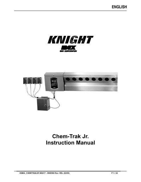
ENGLISH<br />
<strong>Chem</strong>-<strong>Trak</strong> <strong>Jr</strong>.<br />
Instruction Manual<br />
ENMA_CHEMTRAKJR 060417 - 0900590 Rev: REL (02/05) P 1 / 24
TABLE OF CONTENTS<br />
Specifications................................................................................................... 3<br />
System Overview ............................................................................................. 4<br />
Operation......................................................................................................... 5<br />
Installation........................................................................................................ 6<br />
SIB and Interrupt Modules ................................................................................ 8<br />
Wiring Diagram ................................................................................................ 9<br />
Washer Hold Function.................................................................................... 10<br />
Keypad Diagram ............................................................................................ 12<br />
Keypad Descriptions....................................................................................... 13<br />
Formula Selector(s)........................................................................................ 14<br />
Programming (Introduction) ............................................................................ 15<br />
Menu Map...................................................................................................... 16<br />
Menu 1: Memory Functions................................................................... 17<br />
<br />
Menu 2: Setup Routines ........................................................................ 19<br />
<br />
Menu 3: Report Setup Routines ............................................................ 25<br />
<br />
Menu 4: Maintenance Schedule ............................................................ 29<br />
<br />
Menu 5: Programming Routines ........................................................... 30<br />
<br />
Menu 6: Pump Prime Routines.............................................................. 33<br />
<br />
Maintenance .................................................................................................. 34<br />
Troubleshooting ............................................................................................. 35<br />
Parts Diagrams .............................................................................................. 36<br />
Warranty Information...................................................................................... 40<br />
Knight Locations............................................................................................. 40<br />
CAUTION: Wear protective clothing and eyewear when dispensing chemicals or<br />
other materials. Observe safety handling instructions (MSDS) of chemical mfrs.<br />
CAUTION: To avoid severe or fatal shock, always disconnect main power when<br />
servicing the unit.<br />
CAUTION: When installing any equipment, ensure that all national and local<br />
safety, electrical, and plumbing codes are met.<br />
P 2 / 24 ENMA_CHEMTRAKJR 060417 - 0900590 Rev: REL (02/05)
SPECIFICATIONS<br />
Max Number of Washers.................................................................................. 4<br />
Max Number of <strong>Chem</strong>icals................................................................................ 8<br />
Pump/Controller ........................... 53” W x 14” H x 7” D (1.34m x .355m x .178m)<br />
Power Supply.................................8” W x 10” H x 5” D (.203m x .254m x .127m)<br />
Diverter Valve ................................15” W x 8” H x 4” D (.381m x .203m x .102m)<br />
Total Weight................................................................................ 100 lbs (45 kg)<br />
Voltage ........................................................................................... 115 or 230V<br />
Frequency........................................................................................ 50 or 60 Hz<br />
Current .......................................................................................... 1.3A (typical)<br />
Water Pressure................................................................. 30 - 70 PSI / 2 - 5 bar<br />
Water Temperature .............................................................32 - 120°F / 0 - 50°C<br />
Max Distance to Washer (see note 1)............................................ 250 feet / 75M<br />
Peristaltic Pump Duty Cycle (minutes)...............................................2 on / 15 off<br />
<strong>Chem</strong>ical Compatibility .....................................................................(see note 2)<br />
Humidity (max).......................................................................................... 100%<br />
Working Temperature........................................................45 - 140°F / 10 - 60°C<br />
Storage Temperature ..................................................... -40 - 185°F / -40 - 85°C<br />
Life (normal operation).............................................................................5 years<br />
Case Rating................................................................................................IP55<br />
NOTES<br />
(1) Far distance to washers requires longer transfer times.<br />
(2) Peristaltic pump squeeze tubes and other wetted components are constructed of various chemical resistant<br />
materials. Consult Knight for chemical compatibility information and squeeze tube options.<br />
SAFETY SYMBOL EXPLANATIONS<br />
Listed below are explanations of the safety symbols that appear either on the unit, in the instruction manual, or both.<br />
Please familiarize yourself with the meaning of each symbol.<br />
GENERAL CAUTION: This symbol indicates a general safety caution.<br />
SHOCK HAZARD: This symbol indicates that hazardous voltages are inside the<br />
enclosure.<br />
READ MANUAL: This symbol indicates to read the manual for important<br />
instructions and procedures related to safety.<br />
ENMA_CHEMTRAKJR 060417 - 0900590 Rev: REL (02/05) P 3 / 24
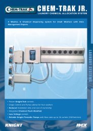
SYSTEM OVERVIEW<br />
<strong>Chem</strong>-<strong>Trak</strong> <strong>Jr</strong>. is a modular system with the Master LFP, CIO <strong>Jr</strong> and Memory Module in one cabinet, and a separate<br />
power supply. Up to eight peristaltic pumps are located in a third cabinet with a flush manifold which includes the<br />
manifold block , check valves, one water solenoid, flow switch, and regulator. A fourth, and separate cabinet, houses<br />
the four diverter valves which are used to control delivery to each respective washer.<br />
A Formula Selector/SIB combination are mounted remotely at each washer. The system can service a maximum of<br />
four washer-extractors. The system can be programmed locally at the Master LFP or globally via a link to Reporter<br />
software using the KCI module. The system stores all programmed features in battery-backed RAM. The battery has<br />
a minimum life of 10 years.<br />
SYSTEM COMPONENTS<br />
• Control Module: The <strong>Chem</strong>-<strong>Trak</strong> <strong>Jr</strong>. control module monitors chemical feed requests for up to 4 washers. When a<br />
washer requests a chemical dosage, the control module dispenses the correct amount, then handles the operation<br />
of the flush and transfer to deliver the chemical to the appropriate washer.<br />
• Flush Manifold: This area of the system houses the flush manifold and checkvalves. The manifold is where all of<br />
the peristaltic pumps inject chemical into. The checkvalves prevent cross-contamination of chemicals.<br />
• Formula Selector & SIB: Remote formula selector integrates with washer signal inputs and sends chemical<br />
requests to the control module. Each washer has its own formula selector that is used by operators for choosing<br />
wash formulas. When a chemical trigger signal is sent by the washer, the SIB transmits the dosage request to the<br />
control module.<br />
• Strobe Alarm(s): The strobe alarm is an audio-visual warning device to alert operators when there is a problem<br />
with the system. When the alarm is activated, there will be various system errors shown on the display of the<br />
control module. The errors are also tracked into memory for later printing a report.<br />
• Pump Cabinet: <strong>Chem</strong>-<strong>Trak</strong> <strong>Jr</strong>. uses reliable Knight peristaltic pumps to deliver up to 8 total chemicals ranging<br />
from 10 oz/min to 40 oz/min.<br />
Pump Cabinet (6 or 8 pumps)<br />
110/230v<br />
50/60Hz<br />
Power<br />
Supply<br />
Water<br />
Flush manifold system<br />
Formula<br />
Selector<br />
SIB<br />
Washer 1<br />
Master<br />
LFP<br />
CIO <strong>Jr</strong><br />
Memory<br />
Module<br />
Formula<br />
<strong>Chem</strong>ical 1 <strong>Chem</strong>ical 5<br />
Selector<br />
SIB<br />
<strong>Chem</strong>ical 2 <strong>Chem</strong>ical 6<br />
<strong>Chem</strong>ical 3 <strong>Chem</strong>ical 7 Washer 2<br />
<strong>Chem</strong>ical 4 <strong>Chem</strong>ical 8<br />
Control Module<br />
KCI<br />
Formula<br />
Selector<br />
SIB<br />
Reporter Software<br />
Washer 3<br />
PC<br />
Formula<br />
Selector<br />
SIB<br />
Washer 4<br />
P 4 / 24 ENMA_CHEMTRAKJR 060417 - 0900590 Rev: REL (02/05)
OPERATION<br />
Normal <strong>Chem</strong>ical Transfer<br />
►<br />
When the system receives a request for chemical, the following sequence occurs. The diverter valve associated with<br />
the washer requesting chemical is activated and the water flush solenoid valve is also activated. After the flush error<br />
delay time (setup in the programming menus) the system will check the flow switch input. If the switch contact is<br />
closed the system will start the pump and run it for the programmed volume. If the switch contact is open the system<br />
will stop, activate the strobe alarm, and display “FE” (indicating flush error) on the formula selector for each washer.<br />
At the end of the pump run time the water flush solenoid will continue to operate for the flush time and transfer time<br />
programmed in the setup. This time should be set long enough to ensure all chemical is flushed through the system<br />
and to the washer. If the flow switch contacts open (for longer than the flush error delay) at any time during the flush<br />
cycle, the system will shut down with a flush error as described above.<br />
If a specific flush time is programmed for the pump that is running, the system will add this additional time to the<br />
normal flush time. If the Halt with Injection feature is used, the <strong>Chem</strong>-<strong>Trak</strong> <strong>Jr</strong>. SIB will hold the washer during the<br />
entire process described above.<br />
Multiple <strong>Chem</strong>ical Requests (one machine)<br />
►<br />
If multiple chemicals have been requested by one machine, then the following sequence occurs. If the Flush Between<br />
feature is used, then the system will activate the programmed flush time between each pump activation to provide a<br />
barrier of water between non-compatible chemicals. This sequence continues until all requested products have been<br />
dispensed. The system then follows the transfer sequence described in the section above to push all chemical and<br />
water to the washer. The maximum number of pumps that can run simultaneously is three total.<br />
Multiple <strong>Chem</strong>ical Requests (multiple machines)<br />
►<br />
If a washer calls for product while the system is active servicing another washer then the system puts the request in a<br />
queue. The washer interface puts the washer into halt mode (if the <strong>Chem</strong>-<strong>Trak</strong> <strong>Jr</strong>. SIB is interfaced with the washer’s<br />
controls) to ensure the chemical does not miss injection to the correct wash cycle step. When the system is ready to<br />
process the request, washer halt is de-activated and a normal transfer sequence will begin.<br />
Multiple Injection Levels<br />
►<br />
Using multiple volume levels allows a pump to dispense different amounts of chemical upon subsequent signals. For<br />
example, on a particular formula, pump 1 could pump 8 ounces of chemical the first time it is signaled, and pump 1<br />
could pump 12 ounces of chemical the second time it is signaled. Up to three volume levels (max) are available per<br />
pump.<br />
Multiple volume levels can be used for any pump on any formula, except the load count pump. Only level 1 can be<br />
programmed on the load count pump (or any other pumps that are signaled at the same time as the load count<br />
pump).<br />
After the load count pump has been triggered (to end the previous formula) the next signal to a pump will dispense<br />
Level 1 amounts. The next washer signal to the same pump will be Level 2 if there is a run or delay time<br />
programmed. If no time is programmed, it will skip Level 2 and go to Level 3. If there is no time programmed on Level<br />
3, it will disregard Level 3 and dispense Level 1 amounts again.<br />
By using run or delay times on the different levels, you can have a plurality of chemical formulas using multiple<br />
signals from the same card or microprocessor. To “use up” a level and NOT dispense product, simply program a “0"<br />
volume and a ”1" second delay time for that level.<br />
ENMA_CHEMTRAKJR 060417 - 0900590 Rev: REL (02/05) P 5 / 24
PRE-INSTALLATION<br />
Before installing <strong>Chem</strong>-<strong>Trak</strong> <strong>Jr</strong>., you should survey the installation site thoroughly to determine materials and tools<br />
that will be needed. You may wish to use the specifications in the front section of this manual as reference. At the<br />
very least, your site survey should included the following.<br />
• Locate a 115 or 230 VAC power source.<br />
• Locate a water source and nearby drain.<br />
• Plan to place the unit in view of the washer line so the operators can see alarms, and also where there is enough<br />
room for chemical containers.<br />
• Plan your delivery lines and the easiest route to each machine for tubing and wiring of the formula selectors.<br />
• Check to make sure that all functions of the laundry machine are operating properly (i.e. drain valve, hot/cold water<br />
solenoids, flush down valves, water level switch, card reader or timer, and machine motor).<br />
• Familiarize yourself with all applicable safety, electrical, and plumbing codes.<br />
• Measure the distance from the chemical supply containers to where the chemical pumps will be mounted.<br />
• Measure the distance from where the system will be mounted to each respective washmachine.<br />
• Make a list of all parts, electrical and plumbing, so you will have everything you need to complete the install.<br />
INSTALLATION<br />
Main Control Cabinets<br />
►<br />
(1) Mount the joggle bracket to the wall using appropriate hardware.<br />
(2) Hang the system on the joggle bracket. There is a 1/4” hole on the lower back wall of the control module cabinet<br />
and pump cabinet to allow the unit to be secured to the wall using appropriate hardware.<br />
(3) Run a drain line from the top port on the 3-way valve to floor drain or nearest trough. The drain line is used to<br />
divert water flow away from manifold (by using the 3-way valve) to relieve pressure from the manifold for<br />
maintenance.<br />
(4) Mount the power supply box and connect to the terminals on the lower right corner of the CIO board in the<br />
control module cabinet (see wiring diagram).<br />
(5) Connect main power input to the power supply box using suitable conduit.<br />
(6) A water inlet assembly is included in the accessory kit. The assembly consists of a pressure regulator, ball valve,<br />
and pipe nipple. Apply a few wraps of PTFE tape to the male pipe threads, then connect to the elbow fitting (inlet<br />
to flush manifold) on the lower right side of the unit.<br />
(7) Run water supply ensuring adequate pressure. Warm water is recommended for best results.<br />
(8) If using SA-12 strobe alarms, mount and wire to the appropriate terminals on the CIO.<br />
(9) Connect multi-link wires for each system if more than one system will be used.<br />
<strong>Chem</strong>ical Pumps & Diverter<br />
►<br />
(1) For each chemical pump, cut suction tube to required length and connect between the pump’s intake (left side)<br />
and the chemical pickup tube. Insert each pickup tube into the correct chemical container. The suction tube<br />
should be the same ID, or larger, than the discharge tubing to prevent air pockets from occurring.<br />
(2) Mount the diverter box using suitable hardware and connect the solenoid valves to the CIO board in the control<br />
module cabinet (see wiring diagram). A color coded cable is provided for connecting the diverter box and the<br />
cable is pre-attached to the CIO board.<br />
(3) Connect the inlet port on the diverter to the bottom fitting on the 3-way valve in the pump cabinet.<br />
(4) Route the delivery lines from the diverter control to each respective washer.<br />
P 6 / 24 ENMA_CHEMTRAKJR 060417 - 0900590 Rev: REL (02/05)
Formula Selector’s and SIB’s<br />
►<br />
One formula selector and one SIB are required for each washer that the <strong>Chem</strong>-<strong>Trak</strong> <strong>Jr</strong>. will feed. Be sure to connect<br />
the formula selector to the appropriate remote terminals on the CIO board (the “remote” numbers shown on the CIO<br />
board correspond to the washer number). Perform the steps below for each washer.<br />
(1) Ensure that main power to the <strong>Chem</strong>-<strong>Trak</strong> <strong>Jr</strong>. is off.<br />
(2) Mount the formula selector to the washer using a mounting bracket or dual-lock fastening strips.<br />
(3) Route the formula selector cable to the unit and connect to the CIO board in the control box (avoid running the<br />
cable near any source of electrical noise such as high voltage AC lines, motor contactors, etc).<br />
(4) Mount the SIB near the washer’s signal source using dual-lock fastening strips. If desired, the SIB can be<br />
mounted right inside the washer’s control box.<br />
(5) Connect the SIB to the formula selector using 3 conductor cable.<br />
(6) Check the signal voltage output from the laundry machine. Measure the voltage between control signal and<br />
signal common, NOT control signal and case ground.<br />
(7) Ensure that power to the washer is off.<br />
(8) Connect signal wires to SIB per wire colors on the label of the SIB. If split commons are required, a resistor can<br />
be removed inside the SIB to allow use of 2 different signal commons (see page 8 for details).<br />
(9) If Auto Formula Select will be used, be sure to choose the correct input on the SIB for the application (see page<br />
21 for details).<br />
(10) If the washer hold feature will be used, the <strong>Chem</strong>-<strong>Trak</strong> <strong>Jr</strong>. SIB must be properly interfaced with the washer to<br />
permit the SIB to pause the washer if other washers are requesting chemical. See the Washer Hold section (on<br />
page 10) for more details.<br />
Remaining Steps<br />
►<br />
(1) Power the system up.<br />
(2) Program the system either at the main keypad, or by uploading a setup (HEX) file using WinReporter.<br />
(3) Prime and calibrate each chemical pump at the main keypad according to the instructions in the programming<br />
section of this manual.<br />
(4) After the system is programmed, observe the operation to ensure all washers are getting chemical and operating<br />
properly. The washer hold feature can be used to ensure proper delivery to each washer.<br />
(5) Check for any water leaks and verify that water pressure is adequate to flush chemical to each washer. Check to<br />
ensure that the flush time and transfer time settings are adequate.<br />
(6) Fully train the staff to service and recognize alarms and how to satisfy them. As well as how to maintain the<br />
system (i.e. squeeze tube lubrication and replacement, check valves, etc).<br />
ENMA_CHEMTRAKJR 060417 - 0900590 Rev: REL (02/05) P 7 / 24
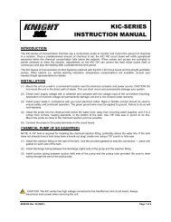
SIB & INTERRUPT MODULES<br />
CONNECTS<br />
TO WASHER’S<br />
CONTROLS<br />
CONNECTS<br />
TO WASHER’S<br />
SIGNALS<br />
CONNECTS<br />
TO FORMULA<br />
SELECTOR<br />
Splitting Signal Commons<br />
►<br />
If you have one signal common (typical) connect it to “COM A” only. If you have two signal commons, you will need to<br />
remove a resistor inside the SIB before connecting common wires! Once the resistor is removed, you can then use<br />
COM A and COM B for different groups of signals shown in the table. Shut off all power sources before continuing.<br />
(1) Remove screws from the bottom of the SIB to open it.<br />
(2) Locate the three resistors marked R15, R14, and R13,<br />
on the left side of the module (each resistor has a single<br />
black band to identify it).<br />
(3) Cut and remove the resistor that will “split” the commons<br />
between the desired pumps. Remove only one resistor.<br />
(4) Close the module and replace screws when finished.<br />
CUT RESISTOR<br />
TO USE COM A<br />
FOR PUMPS<br />
AND COM B<br />
FOR PUMPS<br />
R15 1 — 2 3 — 13<br />
R14 1 — 3 4 — 13<br />
R13 1 — 5 6 — 13<br />
P 8 / 24 ENMA_CHEMTRAKJR 060417 - 0900590 Rev: REL (02/05)
WIRING DIAGRAM<br />
ENMA_CHEMTRAKJR 060417 - 0900590 Rev: REL (02/05) P 9 / 24
WASHER HOLD FUNCTION<br />
The <strong>Chem</strong>-<strong>Trak</strong> <strong>Jr</strong>. System has two halt (washer hold) modes that pause the washer operation to allow sufficient time<br />
for chemical injection to reach the machine. There is also a “maintenance hold” function that halts the washer<br />
operation and puts the chemical request in the queue for later delivery. Below is a brief overview of the purpose for<br />
each halt mode. More information can be found in the Operation section of this manual, and information on<br />
maintenance hold can be found in the Programming section of this manual.<br />
• Normal Hold: The washer is halted if its requesting chemical feed while the system is busy feeding other washers.<br />
• Halt With Injection: Operates same as above (normal hold) but will additionally halt the washer during its own<br />
chemical injection.<br />
• Maintenance Hold: This function is used while performing maintenance on the system, and must be enabled at<br />
the host control panel. While the system is on maintenance hold, any washers that request chemical will be put on<br />
hold and the feed request will be added to the queue to be delivered later when finished with maintenance hold.<br />
When any of the hold functions are activated, a relay on the <strong>Chem</strong>-<strong>Trak</strong> SIB is energized. This relay can be wired<br />
normally open or normally closed depending on the type of washer (examples following). The relay causes the<br />
washer to halt until the relay is de-energized, then allowing the washer to resume normal operation.<br />
An additional halt module can be wired into the <strong>Chem</strong>-<strong>Trak</strong> SIB for applications that require more than one relay<br />
(example following). The halt module has four relays that activate simultaneously with the relay on the SIB to expand<br />
the washer hold capabilities of the <strong>Chem</strong>-<strong>Trak</strong> <strong>Jr</strong>.<br />
Before attempting to wire the machine for the washer hold function, make sure that you have a wiring diagram of the<br />
machine’s controls, and that you fully understand how to perform the necessary electrical changes. Also consider<br />
how this feature may affect the wash cycle operation.<br />
Fixed Timer or Card Reader Type Washers<br />
►<br />
The key to halting a fixed timer or card reader machine is to interrupt the motor that controls the timer or card reader<br />
mechanism. Wire the timer motor to the <strong>Chem</strong>-<strong>Trak</strong> <strong>Jr</strong>. SIB using the normally closed (N/C) configuration as shown in<br />
the diagram below. When the halt feature is active, the relay will open the circuit and thereby pause the washer.<br />
CHEM-TRAK SIB<br />
RELAY WIRED FOR<br />
NORMALLY CLOSED<br />
OPERATION<br />
WASHER TIMER MOTOR<br />
115 VAC (EXAMPLE)<br />
P 10 / 24 ENMA_CHEMTRAKJR 060417 - 0900590 Rev: REL (02/05)
Microprocessor Washer with Pause Control<br />
►<br />
If the washer is microprocessor controlled, check to see if it has a designated input for connecting an external pause<br />
device that operates with “dry contacts” (such as a toggle switch). If the machine has such an input, then the relay on<br />
the <strong>Chem</strong>-<strong>Trak</strong> SIB can be connected using the normally open (N/O) configuration as shown in the diagram below.<br />
When the halt feature is active, the relay will close the circuit and thereby pause the washer.<br />
CHEM-TRAK SIB<br />
WASHER PAUSE CONTROL<br />
RELAY WIRED FOR<br />
NORMALLY OPEN<br />
OPERATION<br />
Microprocessor Washer without Pause Control<br />
►<br />
If the washer is microprocessor controlled but does not have a designated input for connecting an external pause<br />
device, then other circuits on the machine will have to be interrupted using the halt module. The most common<br />
approach is to wire the machine’s water level sensor, hot water fill solenoid, and cold water fill solenoid to the<br />
normally closed contacts on the halt module as shown in the diagram below. When the halt feature is active, the<br />
relays will open the circuits and thereby pause the washer.<br />
NOTE: When the halt module is inter-connected to the <strong>Chem</strong>-<strong>Trak</strong> SIB, then the relay on the SIB can no longer be<br />
used. Only use the relays on the halt module for this type of setup.<br />
CHEM-TRAK SIB<br />
HALT MODULE<br />
NOT USED IN THIS EXAMPLE<br />
5-CONDUCTOR CABLE<br />
WATER LEVEL SENSOR<br />
RELAYS WIRED FOR<br />
NORMALLY CLOSED<br />
OPERATION<br />
H<br />
HOT WATER SOLENOID<br />
C<br />
COLD WATER SOLENOID<br />
ENMA_CHEMTRAKJR 060417 - 0900590 Rev: REL (02/05) P 11 / 24
KEYPAD DIAGRAM<br />
WASHER NUMBER DISPLAY<br />
PROGRAMMING DISPLAY<br />
ALPHANUMERIC KEYPAD<br />
PROGRAMMING KEYPAD<br />
P 12 / 24 ENMA_CHEMTRAKJR 060417 - 0900590 Rev: REL (02/05)
PRIME<br />
<br />
KEYPAD DESCRIPTIONS<br />
The MENU (UP) and MENU (DOWN) keys allow you to move<br />
through the menu selections and pick what you want to do.<br />
<br />
MENU<br />
<br />
MENU<br />
<br />
SCROLL<br />
<br />
SCROLL<br />
The SCROLL keys allow you to move through a particular menu<br />
screen, and pick one of several items to change (like characters<br />
on a screen, etc).<br />
The YES and NO keys allow you to pick whether you want to do<br />
something or not.<br />
YES<br />
NO<br />
The RESET key performs a number of functions. From any main<br />
menu heading, pressing the RESET key allows you to exit the<br />
programming mode and returns the screen to the main display.<br />
From any selection within a main menu, pressing the RESET key<br />
takes you back to that menu’s heading.<br />
RESET<br />
NOTE: Reset can be used to silence alarms and to halt pump<br />
operation; as desired or in an emergency situation. If<br />
pressed, the system will prompt you if you wish to abort the<br />
current job. A YES/NO response will direct the system what<br />
to do.<br />
The ENTER key acknowledges input data and logs it into<br />
memory. It also takes you into a menu for programming.<br />
ENTER<br />
A B C<br />
D E F<br />
G H I<br />
<br />
J K L<br />
<br />
<br />
M N O<br />
<br />
<br />
P Q R<br />
<br />
The alphanumeric keys allow you to input numbers and letters. By<br />
repeatedly pressing any key, any of the letter characters (as well<br />
as the numeric character) can be entered into the menu selection<br />
you are working on.<br />
S T U<br />
<br />
V W X<br />
<br />
Y Z<br />
<br />
The PRIME/CAL key (lower right corner) is used during priming<br />
and calibrating of the chemical pumps.<br />
SPACE<br />
█<br />
CAL.<br />
<br />
ENMA_CHEMTRAKJR 060417 - 0900590 Rev: REL (02/05) P 13 / 24
DISPLAY WINDOW<br />
00 CHEM-TRAK JR 00<br />
DATE 09/05 TIME 16:53:50<br />
W3 BLEACH 010.0 OZ 16:51<br />
W1 DETERG 025.0 OZ 16:47<br />
The main display window shows the status of chemical injections,<br />
and warns of any system error conditions that could cause<br />
potential problems with product delivery. To the left is an example<br />
of what the display might look like during typical operation.<br />
– Top line: Left side shows the step number, which is a reference<br />
point for what the system is doing (i.e. pumping chemical,<br />
flushing, etc). Right side shows the job number, which is a<br />
reference to each product request.<br />
– Second line: Shows the date and time when idle, otherwise will<br />
show what system activity is taking place, such as the status of<br />
a chemical injection in progress.<br />
– Third line: Shows the most recent chemical request history.<br />
Number to the left shows the washer that requested chemical,<br />
followed by the chemical name and dosage pumped, then the<br />
time the job started.<br />
– Bottom line: Same as above. New information is pushed down<br />
the list incrementally.<br />
FORMULA SELECTOR(S)<br />
HALT<br />
INDICATOR<br />
FORMULA<br />
NUMBER<br />
DISPLAY<br />
FORMULA<br />
SELECT<br />
BUTTONS<br />
TIP: Hold down on the<br />
formula select buttons<br />
to rapidly advance the<br />
number<br />
NOTE: FE will display in<br />
the formula select window<br />
if there is a flush error<br />
P 14 / 24 ENMA_CHEMTRAKJR 060417 - 0900590 Rev: REL (02/05)
PROGRAMMING THE SYSTEM<br />
<strong>Chem</strong>-<strong>Trak</strong> <strong>Jr</strong>. programming is done through the use of menu selections. Any menu can be entered by pressing the<br />
ENTER button, or exited by pressing RESET (or in some cases MENU or ). Its that simple! Each of the main<br />
menu headings give an idea of what information can be found, entered, or changed. Within each main menu<br />
selection are several screen “prompts” that walk you through the complete programming process step-by-step.<br />
From the main display screen, you must enter an access code to get into the programming menus. The <strong>Chem</strong>-<strong>Trak</strong><br />
<strong>Jr</strong>. system has two access codes for protection:<br />
• The "main" access code, allows entry into ALL of the menus and functions of the system.<br />
• The "user" access code restricts access to only the Pump Prime Routines menu without the ability of changing<br />
programmed information.<br />
Systems are shipped from the factory with both access codes set to zero. Only a person with the "main" access code<br />
can change the "user" access code (changing codes is explained later in this manual). If desired the two access<br />
codes can be the same, however the user will then have access to ALL of the functions of the system, including the<br />
ability of changing programmed information.<br />
NOTES<br />
IMPORTANT<br />
• It is recommended to clear memory prior to initial programming. See the MEMORY FUNCTIONS menu for details.<br />
• Programmed settings apply to all washers unless otherwise specified.<br />
TO ENTER PROGRAMMING MODE...<br />
ENTER ACCESS CODE<br />
THEN PRESS ENTER<br />
To enter the programming mode, press the ENTER button on the<br />
keypad. The screen at left should appear. If the screen at left does<br />
not appear, wait 2 seconds, press RESET, then press ENTER<br />
again.<br />
When you see the screen at left, type in the access code and<br />
press ENTER. Remember, for a new system, the access code will<br />
be zero (until you change it later).<br />
00 00 00 00 00 00<br />
00 00<br />
This display will appear immediately after gaining access to the<br />
system. The numbers show the percentage of wear for each<br />
squeeze tube. Press any key to continue into programming mode.<br />
Top line: pumps 1 - 6 (from left to right).<br />
Bottom line: pumps 7 - 8 (from left to right).<br />
NOTE: The squeeze tube wear status is also displayed when<br />
logging onto the <strong>Chem</strong>-<strong>Trak</strong> <strong>Jr</strong>. System from your PC (using<br />
WinReporter software).<br />
ON TO PROGRAMMING MENUS<br />
ENMA_CHEMTRAKJR 060417 - 0900590 Rev: REL (02/05) P 15 / 24
MENU MAP<br />
1<br />
*** DISPENSER ***<br />
MEMORY FUNCTIONS<br />
• Clear pump volumes and delay times<br />
• Restore default settings<br />
• Clear sum/cycle report memory<br />
• Set external memory module ID<br />
• Clear external memory module<br />
2<br />
*** DISPENSER ***<br />
SETUP ROUTINES<br />
• Change ID and main access code<br />
• Set date and time<br />
• Select unit of measure<br />
• Setup auto formula select and auto formula reset<br />
• Select load count pump<br />
• Set delay time units/set signal lockout<br />
• Setup flush parameters<br />
• Set transfer time<br />
• Set flush between status<br />
• Set halt with injection<br />
3<br />
*** DISPENSER ***<br />
REPORT SETUP ROUTINES<br />
• Change user access code<br />
• Change report name<br />
• Change formula names and weights<br />
• Change chemical names and costs<br />
• Set squeeze tube warning percentage<br />
• Set shift times and operating zone<br />
• Set washer capacity<br />
• Set signal qualifying time<br />
4<br />
*** DISPENSER ***<br />
MAINTENANCE SCHEDULE<br />
• Date dispenser installed<br />
• Date tubes last changed<br />
• Date tubes last lubed<br />
5<br />
*** DISPENSER ***<br />
PROGRAMMING ROUTINES<br />
• Enable maintenance hold<br />
• Prime pumps<br />
• Calibrate pumps<br />
• View pump flow rates<br />
• Program formula dosages and delay times<br />
6<br />
*** DISPENSER ***<br />
PUMP PRIME ROUTINES<br />
• Enable maintenance hold<br />
• Prime pumps<br />
P 16 / 24 ENMA_CHEMTRAKJR 060417 - 0900590 Rev: REL (02/05)
1<br />
*** DISPENSER ***<br />
MEMORY FUNCTIONS<br />
• Clear pump volumes and delay times<br />
• Restore default settings<br />
• Clear sum/cycle report memory<br />
• Set external memory module ID<br />
• Clear external memory module<br />
NO<br />
CLEAR PUMP VOLUMES ?<br />
PRESS: YES OR NO<br />
YES<br />
This selection clears all formula pump volumes and delay times<br />
back to zero. Press NO if you do not wish to clear pump volumes<br />
at this time. Press YES for new installations, or when completely<br />
re-programming an existing system.<br />
NO<br />
YES<br />
ARE YOU SURE ?<br />
PRESS: YES OR NO<br />
If you entered YES, you are allowed to check and make<br />
sure that you really do want to clear pump volume<br />
information. Press NO if you are not sure that you want<br />
to clear all formula programming.<br />
CLEARING ALL<br />
VOLUMES AND DELAY TIMES<br />
If you pressed YES, all volumes and delay<br />
times will then be cleared.<br />
NO<br />
RESTORE DEFAULT SETTINGS<br />
PRESS: YES OR NO<br />
YES<br />
This selection clears the setup parameters back to their default<br />
values. Press NO if you do not wish to restore default settings at<br />
this time. Press YES for new installations, or when completely reprogramming<br />
an existing system.<br />
CLEARING SETUP<br />
*** PLEASE STAND BY ***<br />
If you chose YES, the setup data is then cleared, and<br />
default settings are restored. When the clearing process<br />
is finished, you will then see the next menu selection.<br />
NO<br />
CLEAR SUM/CYCLE REPORT ?<br />
PRESS: YES OR NO<br />
YES<br />
This selection allows you to clear summary and cycle report<br />
memory. Press NO if you do not wish to clear sum/cycle<br />
information at this time. Press YES to clear the report memory.<br />
A MUST WHEN YOU ARE READY TO TRACK WASHER AND<br />
CHEMICAL INFORMATION! Clearing the sum/cycle report clears:<br />
– Production Summary Report<br />
– Time Stamp Report (Wash Cycle Tracking)<br />
CLEARING ALL SUM/CYCLE<br />
INFORMATION<br />
This shows that report memory is being cleared.<br />
GO TO NEXT PAGE<br />
ENMA_CHEMTRAKJR 060417 - 0900590 Rev: REL (02/05) P 17 / 24
1<br />
*** DISPENSER ***<br />
MEMORY FUNCTIONS<br />
• Continued<br />
NO<br />
SET EXT MEM MODULE ID ?<br />
PRESS: YES OR NO<br />
YES<br />
This menu selection is used to synchronize the ID number of the<br />
external memory module to match the system’s ID.<br />
Press NO for a new installation, or if the external memory module<br />
ID had been set previously. Press YES if you have changed the<br />
ID number in menu #2 (be sure the unit is not be multi-linked with<br />
other systems while performing this step).<br />
NOTE: You will typically need to first set the ID number of the<br />
host, then come back to this menu later to set the ID number for<br />
the external memory module.<br />
NO<br />
YES<br />
ARE YOU SURE ?<br />
PRESS: YES OR NO<br />
You are then asked if you really do want to use this<br />
command. Press YES if you are sure, or press NO to<br />
continue on to the next menu selection without setting<br />
the external memory module ID number.<br />
SETTING EXT MEM MODULE<br />
*** ID TO CURRENT ID ***<br />
When the process is complete, you will be<br />
returned back to the menu heading.<br />
NO<br />
CLEAR MEMORY MODULE ?<br />
PRESS: YES OR NO<br />
YES<br />
This menu selection allows you to clear all time stamp data from<br />
the external memory module.<br />
Press YES for a new installation, or if you wish to clear old data<br />
from the memory module that is no longer needed. Press NO if<br />
you do not wish to clear the memory module (or if you’re not sure)<br />
and you will return to the menu heading.<br />
NOTE: While the memory module can hold a very large amount of<br />
data, it is recommended to periodically clear the module. Be sure<br />
that the old data is no longer needed before proceeding.<br />
NO<br />
YES<br />
ARE YOU SURE ?<br />
PRESS: YES OR NO<br />
You are then asked if you really do want to use this<br />
command. Press YES if you are sure, or press NO to<br />
return back to the menu heading without clearing the<br />
external memory module.<br />
CLEARING MEMORY MODULE<br />
************************<br />
When the process is complete, you will be<br />
returned back to the menu heading.<br />
MEMORY FUNCTIONS MENU HEADING<br />
P 18 / 24 ENMA_CHEMTRAKJR 060417 - 0900590 Rev: REL (02/05)
2<br />
*** DISPENSER ***<br />
SETUP ROUTINES<br />
• Change ID and main access code<br />
• Set date and time<br />
• Select unit of measure<br />
• Setup auto formula select and auto formula reset<br />
• Select load count pump<br />
• Set delay time units/set signal lockout<br />
• Setup flush parameters<br />
• Set transfer time<br />
• Set flush between status<br />
• Set halt with injection<br />
NO<br />
YES<br />
CHANGE ID# ?<br />
PRESS: YES OR NO<br />
This selection allows you to change the ID number of the system.<br />
The ID number is used for communication with a PC to print<br />
reports. It also identifies which host that a report was generated<br />
from when multiple systems are connected together in a daisychain<br />
format known as “multi-linking”.<br />
Press NO if you do not wish to change the ID number at this time.<br />
Press YES to change the ID number (remember to go back to<br />
menu 1 and set the ID number of the external memory module).<br />
NOTE: If two or more systems will be multi-linked together, they<br />
must have separate ID numbers. ID numbers should be set in<br />
increments of ten. For example, set the ID of the first unit to be 10,<br />
the second unit to be 20, the third to be 30, and so on.<br />
NEW CHEM-TRAK JR ID# 00<br />
THEN PRESS ENTER<br />
If you pressed YES, you can now change the system’s<br />
ID number. Use the number keys to enter the new ID,<br />
then press ENTER. Press MENU to continue.<br />
NO<br />
CHANGE MAIN ACCESS CODE ?<br />
PRESS: YES OR NO<br />
YES<br />
This selection allows you to change the “main” access code. The<br />
main access code allows entry into to ALL menus and functions of<br />
the <strong>Chem</strong>-<strong>Trak</strong> <strong>Jr</strong>. Press NO if you do not wish to change the<br />
main access code at this time. Press YES to change the code.<br />
MAIN ACCESS CODE = 000<br />
THEN PRESS ENTER<br />
If you pressed YES, you can now change the system’s<br />
main access code. Pick a number that will be easy to<br />
remember. Use the number keys to enter the new code,<br />
then press ENTER. Press MENU to continue.<br />
TIP: If the main access code is changed, keep a record<br />
of the change in a safe place (in the event that the code<br />
is forgotten). If the record of the code change becomes<br />
misplaced, contact Knight for help.<br />
GO TO NEXT PAGE<br />
ENMA_CHEMTRAKJR 060417 - 0900590 Rev: REL (02/05) P 19 / 24
2<br />
*** DISPENSER ***<br />
SETUP ROUTINES<br />
• Continued<br />
NO<br />
YES<br />
SET DATE & TIME ?<br />
PRESS: YES OR NO<br />
This selection allows you to change the current date and time (as<br />
shown on the main display screen). Press NO if you do not wish<br />
to change the date and time. Otherwise press YES.<br />
HOUR 00 MINUTE 00<br />
MONTH 00 DAY 00 YR 00<br />
Use number buttons to set date and time (military format,<br />
13:00 = 1:00 PM) then press ENTER. Press the MENU<br />
button to move on to the next menu selection.<br />
UNIT OF MEASURE = US<br />
1=US 2=METRIC 3=IMPERIAL<br />
This selection allows you to choose between US, Metric, or<br />
Imperial units of measure. Use the keys to choose the correct<br />
setting, then use MENU to move through this menu selection.<br />
AUTO FORMULA SELECT OFF<br />
1 = OFF 2 = ON<br />
1 2<br />
This selection enables the Automatic Formula Select feature. This<br />
feature allows the washwheel controller to send signals to the<br />
slave and automatically select the correct wash formula.<br />
Washroom personnel no longer select formulas, thereby<br />
eliminating potential mistakes. Press 1 or 2 for the operation of<br />
your choice, then press MENU .<br />
AUTO FORMULA MODE = MICRO<br />
1 = CHART 2 = MICROPROCESSOR<br />
1 2<br />
Press 1 if the machine is controlled by a chart or card<br />
reader, or 2 if the machine is controlled by a<br />
microprocessor. After the display shows your selection<br />
(CHART or MICRO), press MENU .<br />
AFS TIME = 1 SEC<br />
1=1SEC 2=2SEC 5=5SEC<br />
1 2 5<br />
This selection allows you to select the AFS qualifying<br />
time for MICRO mode (only). For a 1 second qualifying<br />
time, a 1 second signal equals formula 1, 2 seconds<br />
equals formula 2, 3 seconds equals formula 3, etc. For a<br />
2 second qualifying time, a 2 second signal equals<br />
formula 1, 4 seconds equals formula 2, 6 seconds equals<br />
formula 3, etc. For a 5 second qualifying time, a 5<br />
second signal equals formula 1, 10 seconds equals<br />
formula 2, 15 seconds equals formula 3, etc.<br />
Press 1, 2, or 5, for the qualifying time of your choice,<br />
then press MENU .<br />
GO TO NEXT PAGE<br />
P 20 / 24 ENMA_CHEMTRAKJR 060417 - 0900590 Rev: REL (02/05)
2<br />
*** DISPENSER ***<br />
SETUP ROUTINES<br />
• Continued<br />
AUTO FORMULA SELECT — HOW IT WORKS<br />
MICRO MODE: This is used for Automatically Selecting Formulas with washwheels that have<br />
microprocessor controllers.<br />
Only SIB inputs 11 - 13 can be used for micro mode AFS. Input 11 does not add any numbers to the<br />
formula selected. Input 12 adds the number 30, and input 13 adds the number 60 to the formula,<br />
regardless of the AFS qualifying time. For example a 20 second signal using input 11 would result in<br />
formula 20 being selected, whereas a 20 second signal to input 12 would result in formula 50 being<br />
selected, and so on.<br />
To operate Micro Mode Automatic Formula Select, choose an available signal output from the<br />
microprocessor that will be dedicated to selecting formulas. Connect the signal from that output to the<br />
Automatic Formula Select input you wish to use (11, 12, or 13). For a micro processor controlled<br />
machine, to change formulas, the FIRST signal to come from the controller must be on the Automatic<br />
Formula Select input line. The length of time this signal is applied (based on the AFS time setting) will<br />
determine the selected formula.<br />
CHART MODE: This is used for automatically selecting formulas for washers with cards or charts to<br />
control the wash formula.<br />
The Automatic Formula Select signal input will be pump 11 (only) on the SIB. Signal inputs 1 - 7 are<br />
used for adding up the correct formula number.<br />
To operate Chart Mode Automatic Formula Select, choose an available signal track on the chart or card<br />
that will be dedicated to selecting formulas. Connect the signal from that track to the Automatic Formula<br />
select input you designated.<br />
The FIRST cut in the chart or card must be on the Automatic Formula Select Signal track. Thirty seconds<br />
after this cut begins, the dispenser will “look” at signal inputs 1 through 7 and evaluate the formula<br />
number selected (any signal combination higher than 90 will revert the system to formula 90).<br />
The formula selector display will acknowledge the correct formula. Once the formula select process is<br />
finished, pump input signals return to normal operation. All pump signals must turn off for a minimum of<br />
five seconds, then retriggered for a pump to operate.<br />
Example: the chart cuts below would automatically select formula #9 after 30 seconds.<br />
CHART/CARD DIRECTION <br />
███ SIB PUMP #1 SIGNAL INPUT > ADD 1<br />
SIB PUMP #2 SIGNAL INPUT > ADD 2<br />
SIB PUMP #3 SIGNAL INPUT > ADD 4<br />
███ SIB PUMP #4 SIGNAL INPUT > ADD 8<br />
SIB PUMP #5 SIGNAL INPUT > ADD 16<br />
SIB PUMP #6 SIGNAL INPUT > ADD 32<br />
SIB PUMP #7 SIGNAL INPUT > ADD 64<br />
GO TO NEXT PAGE<br />
██████<br />
SIB INPUT #11 AUTO FORMULA SELECT SIGNAL<br />
ENMA_CHEMTRAKJR 060417 - 0900590 Rev: REL (02/05) P 21 / 24
2<br />
*** DISPENSER ***<br />
SETUP ROUTINES<br />
• Continued<br />
CHOOSE LOAD COUNT<br />
PUMP # 00 PRESS ENTER<br />
This sets which pump is being used to count loads. Always enter<br />
the last pump in the system that will receive a signal. When a<br />
cycle is run, the last pump “stamps” the timing data into memory<br />
(for reports and other purposes). Enter the number of the load<br />
count pump and press ENTER. Press MENU to continue.<br />
NOTE: The load count pump must be signaled on every formula<br />
for proper wash cycle tracking data. When the load count pump is<br />
signaled, all volume levels for that formula are reset to level 1.<br />
This setting applies to all washers using the <strong>Chem</strong>-<strong>Trak</strong> <strong>Jr</strong>.<br />
AUTO FORM RESET DISABLE<br />
1=ENABLED 2=DISABLED<br />
1 2<br />
If enabled, this feature resets the formula number to 00 after the<br />
load count pump activates. In cases where automatic formula<br />
select is OFF (formulas selected manually), this feature ensures<br />
that an operator cannot wash a load with the wrong formula.<br />
When a washcycle is finished, the next formula must be manually<br />
chosen. Make your selection, then press MENU to continue.<br />
DELAY TIME UNITS = SEC<br />
1 = MINUTES 2 = SECONDS<br />
1 2<br />
This selection allows you to choose the delay unit of measure.<br />
Some signals only need to be delayed for a few seconds (i.e. to<br />
avoid dumping chemical onto dry linen), others may need longer<br />
delay times. Select the delay time unit of measure, then press<br />
MENU to continue.<br />
5 MIN SIGNAL LOCKOUT OFF<br />
1= OFF 2= ON<br />
1 2<br />
This feature helps prevent unwanted injections that are caused by<br />
“erroneous” signals from the washer (example: when the water<br />
level goes low and a fill valve activates). Make your selection,<br />
then press MENU to continue.<br />
WATER FLUSH TIME<br />
= 40 SECONDS<br />
This sets the time the flush solenoid will activate after the pumps<br />
have finished. Type in the flush time (range is 10 - 99 seconds)<br />
required to clear the chemical from the tube, then press ENTER.<br />
Press MENU to move on to the next menu.<br />
TIP: Flush time should be set long enough to completely clear<br />
chemical from the delivery tube. Determine this setting based on<br />
the thickest product that will be used. This setting is particularly<br />
important if using the “flush between pumps” option.<br />
GO TO NEXT PAGE<br />
P 22 / 24 ENMA_CHEMTRAKJR 060417 - 0900590 Rev: REL (02/05)
2<br />
*** DISPENSER ***<br />
SETUP ROUTINES<br />
• Continued<br />
TRANSFER TIME<br />
WASHER 1 25 SECONDS<br />
This selection sets the amount of time that the diverter solenoid<br />
will activate, after the flush time expires, to deliver product to the<br />
washer. Type in the washer number and transfer time (range is 0 -<br />
99 seconds) then press ENTER. Repeat for each washer in use.<br />
Press MENU to continue.<br />
TIP: The transfer time should be set long enough to deliver all<br />
chemicals to each respective washer (based on washer distance<br />
and product viscosity). Determine this setting based on the<br />
thickest product that will be used.<br />
PUMP FLUSH TIME<br />
PUMP 01 00 SECONDS<br />
This selection sets an additional amount of time that will be added<br />
to the normal flush time during transfer. Each pump can have its<br />
own flush time if desired (range is 0 - 99 seconds). The purpose of<br />
this setting is to add extra flush time for pumps that have very<br />
viscous products. This helps to ensure that no chemical residue is<br />
left in the flush line.<br />
NOTE: If two (or more) pumps run together and each one has a<br />
flush time, then the longest flush time will be used during transfer.<br />
FLUSH ERROR DELAY<br />
= 05 SECONDS<br />
The system has a flow switch that is used to verify actual water<br />
flow. This setting tells the system at what point during the flush<br />
cycle to check the flow switch state (open or closed).<br />
It is recommended that this setting be no less than 05 seconds.<br />
Make your selection and press ENTER. Press MENU to<br />
continue. If absolutely necessary, this setting can be set to 00<br />
which will turn this feature “off”, and the flow switch input will not<br />
be checked (no FLUSH ERROR warnings will be produced).<br />
NOTE: The flush solenoid will start before the pump. After the<br />
flush error delay time, if water flow is good, the pump will start. If<br />
water flow is bad, a flush error will occur and the system will stop.<br />
In this case, no chemical residue will be left in the flush manifold.<br />
FLUSH BETWEEN PUMPS = OFF<br />
1 = OFF 2 = ON<br />
1 2<br />
This selection allows you to choose if the system will add flush<br />
water between chemical injections before transferring all<br />
chemicals to the washer. This provides a barrier of water between<br />
non-compatible chemicals in situations where the washer calls for<br />
multiple chemicals at the same time.<br />
Make your choice, then press MENU to continue.<br />
GO TO NEXT PAGE<br />
ENMA_CHEMTRAKJR 060417 - 0900590 Rev: REL (02/05) P 23 / 24
2<br />
*** DISPENSER ***<br />
SETUP ROUTINES<br />
• Continued<br />
1 2<br />
HALT W/INJECTION = OFF<br />
1= ON 2= OFF<br />
This feature allows the SIB to pause the washer’s operation (halt)<br />
while its own chemical injection is taking place. This can be<br />
helpful in the following applications:<br />
– Excessive pump run time (due to product viscosity, pump size).<br />
– Far distance to the washer (longer flush and transfer times).<br />
– Low water pressure.<br />
The <strong>Chem</strong>-<strong>Trak</strong> SIB has special relay contacts that can be<br />
connected to the washer’s controls to halt machine operation.<br />
Even if this feature is turned off, the SIB will still halt the washer if<br />
requesting chemical while the system is busy feeding other<br />
washers. Make your selection, then press MENU to continue.<br />
LEVEL SENSORS = DISABLED<br />
1 = ENABLED 2 = DISABLED<br />
Disregard — for future use (leave setting on DISABLED). Press<br />
MENU to return to the menu heading.<br />
1 2<br />
SETUP ROUTINES MENU HEADING<br />
P 24 / 24 ENMA_CHEMTRAKJR 060417 - 0900590 Rev: REL (02/05)
3<br />
*** DISPENSER ***<br />
REPORT SETUP ROUTINES<br />
• Change user access code<br />
• Change report name<br />
• Change formula names and weights<br />
• Change chemical names and costs<br />
• Set squeeze tube warning percentage<br />
• Set shift times and operating zone<br />
• Set washer capacity<br />
• Set signal qualifying time<br />
NO<br />
CHANGE USER ACCESS CODE?<br />
PRESS: YES OR NO<br />
YES<br />
This selection allows you to change the user access code. The<br />
user access code allows access to only the pump prime menu of<br />
the <strong>Chem</strong>-<strong>Trak</strong> <strong>Jr</strong>. and allows printing-only when using<br />
WinReporter PC software. Pressing NO allows you to move<br />
through this menu selection.<br />
USER ACCESS CODE = 000<br />
THEN PRESS ENTER<br />
If you entered YES, you will be prompted for a new user<br />
access code. Use the keys to enter the new data, and<br />
press ENTER when done. Press MENU to move<br />
through the menu selection.<br />
CHANGE REPORT NAME ?<br />
PRESS: YES OR NO<br />
The report name is what is printed on the report heading. Pressing<br />
NO allows you to move through this menu selection.<br />
NO<br />
YES<br />
▓<br />
If you entered YES, you can change the report name<br />
(use the SCROLL and lettered keys to enter the new<br />
data, and press ENTER when done). Press MENU <br />
when finished to move through this menu selection.<br />
TIP: Entering the report name in the center of the display<br />
window will center it at the top of the report.<br />
GO TO NEXT PAGE<br />
ENMA_CHEMTRAKJR 060417 - 0900590 Rev: REL (02/05) P 25 / 24
*** DISPENSER ***<br />
3 • Continued<br />
REPORT SETUP ROUTINES<br />
NO<br />
CHANGE FORMULA NAME AND<br />
WEIGHT? PRESS: YES OR NO<br />
YES<br />
This menu selection allows you to change the formula names and<br />
load weight for each formula. Giving each formula a descriptive<br />
name makes the system more user-friendly. Load weights are<br />
used for data-tracking purposes to generate reports. Pressing NO<br />
allows you to move through this menu selection.<br />
FORMULA 01<br />
FORMULA 01<br />
If you entered YES, you will first change the formula<br />
names. When finished changing all formula names,<br />
press MENU to move on to the next display for<br />
changing load weights.<br />
TIP: First select the formula number on the top line and<br />
press ENTER...the current formula name will appear on<br />
the bottom line. Then change the name on the bottom<br />
line and press ENTER again to lock-in the new data.<br />
FORMULA 01<br />
LOAD WEIGHT 000 LBS<br />
Now enter the load weight for each formula used. When<br />
finished changing load weights, press MENU to move<br />
on to the next menu selection.<br />
TIP: First select the formula number on the top line and<br />
press ENTER...the current load weight will appear on the<br />
bottom line. Then change weight on the bottom line and<br />
press ENTER again to lock-in the new data.<br />
CHANGE CHEMICAL NAMES<br />
PRESS: YES OR NO<br />
This is the type of chemical for each pump on the system.<br />
Pressing NO allows you to move through this menu selection.<br />
NO<br />
YES<br />
PUMP 01<br />
PUMP-01<br />
If you entered YES, you can change the chemical name<br />
for each pump (using the SCROLL and lettered keys to<br />
enter the new data). Press MENU to move through this<br />
menu selection.<br />
TIP: First select the pump number on the top line and<br />
press ENTER...the current name for the pump you<br />
selected will be displayed on the bottom line. Then<br />
change the information on the bottom line and press<br />
ENTER again to lock-in the new pump name.<br />
GO TO NEXT PAGE<br />
P 26 / 24 ENMA_CHEMTRAKJR 060417 - 0900590 Rev: REL (02/05)
*** DISPENSER ***<br />
3 • Continued<br />
REPORT SETUP ROUTINES<br />
CHANGE PRODUCT COSTS ?<br />
PRESS: YES OR NO<br />
This menu selection allows you to change costs for each product.<br />
Pressing NO allows you to move through this menu selection.<br />
NO<br />
YES<br />
PUMP 01<br />
$00.00 /GALS<br />
If you entered YES, you can change the cost for each<br />
chemical (using the SCROLL and number keys to enter<br />
the new data). Press MENU to move through this<br />
menu selection.<br />
TIP: First select the pump number on the left side of the<br />
display and press ENTER...the product cost for the pump<br />
you selected will be displayed on the right side. Then<br />
change the information on the right side and press<br />
ENTER again to lock-in the new product cost.<br />
SQUEEZE TUBE WARNING<br />
= 00 %<br />
This menu selection allows you to set the point at which a<br />
squeeze tube warning will occur. The system keeps track of the<br />
re-calibration data and calculates the percentage of wear based<br />
on the reduction in flow rate from when the squeeze tube was last<br />
changed. The status of the tube wear (and warnings, if any) will<br />
appear when accessing the system or using WinReporter.<br />
Use the number keys to enter the percentage (range is 0% - 50%)<br />
then press ENTER. Press MENU to return to the menu<br />
heading.<br />
TIP: This setting is based largely on customer preference. You<br />
may wish to start off with a nominal setting of 25%, then monitor<br />
the wear patterns of the squeeze tubes throughout their usage.<br />
After developing a trend history, you can adjust this setting for<br />
exactly when you want the warning to occur.<br />
WANT TO SET SHIFT TIMES ?<br />
PRESS: YES OR NO<br />
This selection allows you to enter the shift times (the start time for<br />
each work shift in the washroom) for the report. Pressing NO<br />
allows you to move through this menu selection.<br />
YES<br />
NO<br />
START TIMES #1 06:00<br />
#2 11:00 #3 17:00<br />
If you entered YES, you can change the start time for<br />
each washroom work shift. Use SCROLL and the<br />
numbered keys to enter the new data, then press<br />
ENTER. Shift times are entered on a 24 hour clock cycle<br />
(like military time). Press MENU to continue.<br />
GO TO NEXT PAGE<br />
ENMA_CHEMTRAKJR 060417 - 0900590 Rev: REL (02/05) P 27 / 24
*** DISPENSER ***<br />
3 • Continued<br />
REPORT SETUP ROUTINES<br />
NO<br />
SET OPERATING ZONE ?<br />
PRESS: YES OR NO<br />
YES<br />
This selection allows you to select whether or not you wish to<br />
establish “on” and “off” times of operation for the system. The<br />
default start and end times (shown below) allow the system to<br />
dispense chemical at any time, day or night.<br />
When the system is out of the operating zone, any trigger signals<br />
that are received will be ignored, and chemicals will not be<br />
dispensed. Pressing NO allows you to move through this menu<br />
selection.<br />
START TIME 00:00<br />
END TIME 24:00<br />
If you selected YES, you will be prompted to establish<br />
the “on” and “off” times of operation for the system. Use<br />
the keys to enter the new data, then press ENTER.<br />
Actual time of day is entered on a 24-hour clock cycle,<br />
like military time. Press MENU to continue.<br />
WASHWHEEL LOAD CAPACITY<br />
WASHER 1 000 LBS<br />
This selection allows you to enter the load capacity for each<br />
washer. Use the SCOLL and number keys to enter the washer<br />
number and corresponding machine weight, then press ENTER<br />
when done. Press MENU to continue.<br />
SIGNAL QUALIFYING TIME<br />
005 SECONDS (1-120)<br />
This selection allows you to set the time required for a supply<br />
signal from the washer to be recognized. The supply signal<br />
duration must meet or exceed the qualify time setting to activate a<br />
pump. Choose a time from 1 - 120 seconds (default setting is 5<br />
seconds) and press ENTER. Then press MENU to continue.<br />
NOTE: This feature can be used as a “filter” for stray signals (or<br />
ghost signals) that erroneously trigger a pump. Determine the<br />
normal signal duration from the washer and set the signal qualify<br />
time to be slightly shorter than the washer’s supply signals. For<br />
example, if the supply signals are always 30 seconds in duration,<br />
set the signal qualify time to be 25 seconds.<br />
REPORT SETUP ROUTINES MENU HEADING<br />
P 28 / 24 ENMA_CHEMTRAKJR 060417 - 0900590 Rev: REL (02/05)
4<br />
*** DISPENSER ***<br />
MAINTENANCE SCHEDULE<br />
• Date dispenser installed<br />
• Date tubes last changed<br />
• Date tubes last lubed<br />
DISPENSER INSTALLED<br />
00/00/00<br />
This selection allows you to enter the date that the system was<br />
installed. (Use the SCROLL and number keys to enter the new<br />
data, and press ENTER when done). Press MENU to move thru<br />
this menu selection.<br />
SQUEEZE TUBES CHANGED<br />
PUMP 01 00/00/00<br />
This selection allows you to enter the date that the squeeze tubes<br />
were last changed. (Use the SCROLL and number keys to enter<br />
the new data, and press ENTER when done). Press MENU to<br />
move thru this menu selection.<br />
NOTE: The squeeze tube changed date will be automatically<br />
updated when calibrating pumps (in menu #5) and responding<br />
“YES” when prompted if you are using a new squeeze tube.<br />
SQUEEZE TUBES LAST LUBED<br />
PUMP 01 00/00/00<br />
This selection allows you to enter the date that the squeeze tubes<br />
were last lubricated. (Use the SCROLL and number keys to enter<br />
the new data, and press ENTER when done). Press MENU to<br />
move on to the next menu.<br />
MAINTENANCE SCHEDULE MENU HEADING<br />
ENMA_CHEMTRAKJR 060417 - 0900590 Rev: REL (02/05) P 29 / 24
5<br />
*** DISPENSER ***<br />
PROGRAMMING ROUTINES<br />
• Enable maintenance hold<br />
• Prime pumps<br />
• Calibrate pumps<br />
• View pump flow rates<br />
• Program formula dosages and delay times<br />
ENABLE MAINTENANCE HOLD ?<br />
PRESS: YES OR NO<br />
This feature allows you to halt the washers and chemical feed<br />
while performing maintenance. Choose YES or NO to continue (if<br />
“SYSTEM BUSY” appears, wait 30 seconds then try again).<br />
NO<br />
YES<br />
MAINTENANCE HOLD ENABLED<br />
HIT RESET KEY TO RESUME<br />
This display shows that the system is on maintenance<br />
hold. If a feed request is received, the washer will be<br />
halted (by the SIB) and the request will be put in the<br />
queue for later delivery. Press RESET to end the hold<br />
and resume normal operation. Or press MENU to<br />
advance to the next step and continue the hold.<br />
PRIME PUMPS ?<br />
PRESS: YES OR NO<br />
This allows you to prime chemical pumps (necessary for proper<br />
calibration). Choose YES or NO to continue.<br />
NO<br />
YES<br />
SEND PRODUCT TO WASHER<br />
PRESS ENTER 1<br />
Choose the washer that you want product sent to during<br />
the priming process, then press ENTER.<br />
PRIME PUMP 01<br />
PUSH PRIME TO START/STOP<br />
Choose the pump you wish to prime, then use the<br />
PRIME/CAL button to start and stop the pump.<br />
TRANSFER TO WASHER ?<br />
PRESS: YES OR NO<br />
You can choose if you wish to transfer the product to the<br />
selected washer at this time. Choose YES or NO.<br />
NO<br />
YES<br />
EMPTYING VESSEL<br />
Disregard — for future use.<br />
TRANSFERRING-WASHER1 060<br />
<strong>Chem</strong>ical will transfer to the washer and the<br />
display will count down the remaining time till<br />
the process is finished. The count down is a<br />
sum of flush time, and transfer time and will be<br />
activated in this order.<br />
GO TO NEXT PAGE<br />
P 30 / 24 ENMA_CHEMTRAKJR 060417 - 0900590 Rev: REL (02/05)
5<br />
*** DISPENSER ***<br />
PROGRAMMING ROUTINES<br />
• Continued<br />
NO<br />
YES<br />
CALIBRATE PUMPS<br />
PRESS: YES OR NO<br />
This selection allows you to automatically calibrate each pump.<br />
Calibrating “teaches” the system the actual flow rate of the pump.<br />
Accurate flow rates are important for delivering the correct amount<br />
of product that’s called for in the formula volume settings.<br />
SEND PRODUCT TO WASHER<br />
PRESS ENTER 1<br />
Choose the washer that you want product sent to during<br />
the calibration process, then press ENTER.<br />
CALIBRATE PUMP 01<br />
PRESS CAL. TO START<br />
Use a large container for the most accurate pump<br />
calibrations. Fill your container with product and place<br />
under the suction tube of the pump you wish to calibrate<br />
Be sure the tube is primed, then note the amount of<br />
chemical in the container.<br />
Choose the pump number you are calibrating, then press<br />
the CAL button to start the pump. After about 30<br />
seconds, press the CAL button again to stop the pump.<br />
ENTER CALIBRATION<br />
VOL PUMPED = 000.0 OZS<br />
Check the amount of chemical left in the container and<br />
subtract from the previous step to see how much<br />
chemical was actually pumped. Enter this as the “volume<br />
pumped” (OZ or ML) then press ENTER to continue.<br />
NO<br />
NEW PUMP SQUEEZE TUBE<br />
PRESS: YES OR NO<br />
YES<br />
The system keeps track of squeeze tube wear based on<br />
the reduction in flow rate from the last time the squeeze<br />
tube was changed. If you press YES, the system will<br />
remember the new flow rate that you are now calibrating<br />
as a point of reference. The squeeze tube changed date<br />
will also be updated automatically in the Maintenance<br />
Schedule (menu #4). Press YES or NO to continue.<br />
EMPTYING VESSEL<br />
Disregard — for future use.<br />
TRANSFERRING-WASHER1 060<br />
<strong>Chem</strong>ical will then transfer to the washer. The display will<br />
show the remaining time till the process is finished. The<br />
count down on the display is a combination of flush time,<br />
and transfer time and will be activated in this order.<br />
GO TO NEXT PAGE<br />
ENMA_CHEMTRAKJR 060417 - 0900590 Rev: REL (02/05) P 31 / 24
5<br />
*** DISPENSER ***<br />
PROGRAMMING ROUTINES<br />
• Continued<br />
FLOW RATES / MIN<br />
P-01 38.6 OZS 0275MLU<br />
The system calculates the flow rate of the pump and then<br />
displays the result. To the left is an example of what a<br />
flow rate might look like (the MLU number is for<br />
reference only by Knight personnel). Press MENU to<br />
calibrate another pump or press MENU to continue.<br />
NOTE: You can manually enter or change the flow rates<br />
if necessary. Use the PRIME/CAL button to alternate OZ/<br />
GAL, or ML/L.<br />
VIEW PUMP CALIBRATION<br />
PRESS: YES OR NO<br />
This menu selection allows you to view existing pump<br />
calibrations. Choose YES or NO to continue.<br />
YES<br />
NO<br />
FORM 01 LEVEL 1 PUMP 01<br />
VOL 000.0 OZS DELAY 000<br />
This menu selection allows you to enter pump volumes and delay<br />
times for the formulas you will use. The system is capable of 90<br />
total formulas. You can decide how you want to use the formulas.<br />
For example, you can program all 90 formulas to be shared by all<br />
washers. Or you can program certain “groups” of formulas to be<br />
used by only certain washers (such as formulas 1 - 20 for washer<br />
1, formulas 21 - 40 for washer 2, etc). When finished<br />
programming, press MENU to move on to the next menu.<br />
TIP: This selection can be used to simply review programmed<br />
formula settings. By entering the formula number, volume level,<br />
and pump number, and then pressing ENTER, the programmed<br />
volume and delay time will be displayed.<br />
TIP: To change the programmed information, first select the<br />
formula number, volume level, and pump number on the top line<br />
and press ENTER (as mentioned above)...the current settings will<br />
be displayed on the bottom line. Then change the information on<br />
the bottom line and press ENTER again to lock-in the new data.<br />
• For US and Imperial units of measure, formula volume settings are programmed in ounces only (the max<br />
allowed is 999.9 ounces). For Metric units of measure, formula volume settings are programmed in<br />
milliliters only (the max allowed is 9999 milliliters).<br />
• The maximum run time for any pump is 255 seconds. If a formula volume is programmed that will cause a<br />
pump to exceed 255 seconds (base on that pump’s flow rate) the pump will not activate when signaled.<br />
• Delay times can be used when washer signals do not occur at optimum times for chemical dispensing.<br />
Maximum delay times are 255 seconds or minutes. Selection of seconds or minutes is done in the<br />
Dispenser Setup Routines menu.<br />
• Pumped volumes of up to 4095.9 ounces, or 40959 milliliters will be printed on the cycle report. Pumped<br />
volumes over this amount will result in the symbols *VOL? appearing on the cycle report.<br />
PROGRAMMING ROUTINES MENU HEADING<br />
P 32 / 24 ENMA_CHEMTRAKJR 060417 - 0900590 Rev: REL (02/05)
6<br />
*** DISPENSER ***<br />
PUMP PRIME ROUTINES<br />
• Enable maintenance hold<br />
• Prime pumps<br />
ENABLE MAINTENANCE HOLD ?<br />
PRESS: YES OR NO<br />
This feature allows you to halt the washers and chemical feed<br />
while performing maintenance. Choose YES or NO to continue (if<br />
“SYSTEM BUSY” appears, wait 30 seconds then try again).<br />
NO<br />
YES<br />
MAINTENANCE HOLD ENABLED<br />
HIT RESET KEY TO RESUME<br />
This display shows that the system is on maintenance<br />
hold. If a feed request is received, its washer will be<br />
halted (by the SIB or Interrupt Module) and the request<br />
will be put in the queue for later delivery. Press RESET<br />
to end the hold and resume normal operation. Or press<br />
MENU to advance to the next step<br />
SEND PRODUCT TO WASHER<br />
PRESS ENTER 1<br />
Choose the washer that you want product sent to during the<br />
priming process and press ENTER.<br />
PRIME PUMPS ?<br />
PRESS: YES OR NO<br />
This menu allows you to prime the chemical pumps. Choose YES<br />
or NO to continue.<br />
YES<br />
NO<br />
PRIME PUMP 01<br />
PUSH PRIME TO START/STOP<br />
Choose the pump you wish to prime, then use the<br />
PRIME/CAL button to start and stop the pump.<br />
TRANSFER TO WASHER ?<br />
PRESS: YES OR NO<br />
You can choose if you wish to transfer the product to the<br />
selected washer. Choose YES or NO.<br />
YES<br />
NO<br />
EMPTYING VESSEL<br />
Disregard — for future use.<br />
TRANSFERRING-WASHER1 060<br />
<strong>Chem</strong>ical will transfer to the washer and the<br />
display will count down the remaining time till<br />
the process is finished. The count down is a<br />
sum of flush time and transfer time and will be<br />
activated in this order.<br />
FLUSH VESSEL TO DRAIN<br />
PRESS: YES OR NO<br />
Disregard — for future use. Press NO to continue.<br />
PRIME ROUTINES MENU HEADING<br />
ENMA_CHEMTRAKJR 060417 - 0900590 Rev: REL (02/05) P 33 / 24
MAINTENANCE<br />
Good maintenance habits are key to getting the best performance out of your equipment. The following service items<br />
are recommended for normal operation. The intervals may vary depending on chemical affect and actual usage.<br />
NOTE: There is a 3-way valve on the output side of the flush manifold that is provided for servicing. This valve<br />
relieves pressure from the manifold for changing squeeze tubes, checkvalves, or any other plumbed manifold part<br />
Service: Lube squeeze tubes.<br />
Interval: Once a month.<br />
(1) Remove the faceplate of the pump.<br />
(2) Apply a thin bead of Tube Lube to the inner surface<br />
(the side that the rollers contact) of the squeeze<br />
tube between the 9 o’clock and 3 o’clock positions.<br />
Avoid getting lube near the pinch points where the<br />
bottom of the faceplate grips the tube.<br />
(3) Put the faceplate back on the pump.<br />
(4) The next time the pump activates, the lubricant will<br />
be evenly distributed.<br />
Service: Replace squeeze tubes.<br />
Interval: Every 6 months, or as needed.<br />
(1) Bleed any pressure from discharge line.<br />
(2) Disconnect suction and discharge lines from tube.<br />
(3) Remove the faceplate of the pump.<br />
(4) Pull old tube out, being careful not to splash<br />
chemical. Insert new tube by squeezing into place.<br />
(5) Apply lube per step 2 above.<br />
(6) Put the faceplate back on the pump.<br />
(7) Re-connect suction and discharge lines from tube.<br />
Service: Replace manifold checkvalves.<br />
Interval: 3 times a year, or as needed.<br />
(1) Bleed any pressure from discharge line.<br />
(2) Disconnect chemical line from barb fitting.<br />
(3) Remove checkvalve from manifold by turning it<br />
counter-clockwise.<br />
(4) Wrap the threads of the new checkvalve with PTFE<br />
tape (2 - 3 turns) and install into the manifold being<br />
careful not to over-tighten.<br />
(5) Re-connect chemical line to barb fitting.<br />
P 34 / 24 ENMA_CHEMTRAKJR 060417 - 0900590 Rev: REL (02/05)
TROUBLESHOOTING<br />
Formula selector does not light up - no power:<br />
• Check fuses — replace if necessary.<br />
• Check for loose wiring connections.<br />
• Check voltage at main connection — refer to wiring<br />
diagram.<br />
Pumps do not trigger from signals:<br />
• Check signal voltage and duration.<br />
• Check for flush error — press RESET to clear.<br />
• Check pump volume and delay time settings.<br />
• Pump may be counting down a "lockout" time (if used)<br />
from a previous activation.<br />
• Pump may be trying to skip a level.<br />
• Pump flow rate not set, or incorrect<br />
Pumps will not turn when trying to prime, or<br />
during a washcycle:<br />
• Check for loose pump motor wires.<br />
• Check for voltage from circuit board to motor.<br />
• Check for mechanical binding of moving parts.<br />
Pumps trigger more than once during cycle:<br />
• Check supply signal input for repeat signals from<br />
washmachine.<br />
• Check signal lock-out function.<br />
Flush errors keep occurring:<br />
• Check to see if a flush manifold is operating correctly.<br />
• Check flow switch for proper connection to CIO board.<br />
• Check for adequate water flow (clean debris from filter<br />
screen at water inlet).<br />
• Check flush error delay setting and adjust if needed.<br />
• Press RESET to clear flush errors — pumps will not<br />
run during flush error.<br />
Flush solenoid does not open:<br />
• Check for loose wire connections to CIO board.<br />
• Check for adequate water pressure.<br />
• Check for obstruction inside solenoid.<br />
• Check condition of diaphragm inside solenoid.<br />
Pumps run but do not dispense product:<br />
• Check product containers.<br />
• Check squeeze tube for wear.<br />
• Check condition of roller and pump housing.<br />
• Check for air leaks on suction line.<br />
• Check for blockage from pump tube into the<br />
checkvalve on the flush manifold.<br />
ENMA_CHEMTRAKJR 060417 - 0900590 Rev: REL (02/05) P 35 / 24
PARTS DIAGRAM — PUMP CABINET<br />
P 36 / 24 ENMA_CHEMTRAKJR 060417 - 0900590 Rev: REL (02/05)
PARTS DIAGRAM — CONTROLLER & POWER SUPPLY<br />
ENMA_CHEMTRAKJR 060417 - 0900590 Rev: REL (02/05) P 37 / 24
PARTS DIAGRAM — MANIFOLD & DIVERTER<br />
P 38 / 24 ENMA_CHEMTRAKJR 060417 - 0900590 Rev: REL (02/05)
NOTES<br />
ENMA_CHEMTRAKJR 060417 - 0900590 Rev: REL (02/05) P 39 / 24
DISCLAIMER<br />
Knight LLC does not accept responsibility for the mishandling, misuse, or non-performance of the described items<br />
when used for purposes other than those specified in the instructions. For hazardous materials information consult<br />
label, MSDS, or Knight LLC. Knight products are not for use in potentially explosive environments. Any use of our<br />
equipment in such an environment is at the risk of the user, Knight does not accept any liability in such<br />
circumstances.<br />
WARRANTY<br />
All Knight controls and pump systems are warranted against defects in material and workmanship for a period of<br />
ONE year. All electronic control boards have a TWO year warranty. Warranty applies only to the replacement or<br />
repair of such parts when returned to factory with a Knight Return Authorization (KRA) number, freight prepaid, and<br />
found to be defective upon factory authorized inspection. Bearings and pump seals or rubber and synthetic rubber<br />
parts such as “O” rings, diaphragms, squeeze tubing, and gaskets are considered expendable and are not covered<br />
under warranty. Warranty does not cover liability resulting from performance of this equipment nor the labor to<br />
replace this equipment. Product abuse or misuse voids warranty.<br />
Knight Headquarters<br />
Tel +1 (949) 595 4800<br />
Toll Free (800) 854 3764<br />
Fax +1 (949) 595 4801<br />
> Knight Canada<br />
Tel +1 (905) 542.2333<br />
Fax +1 (905) 542.1536<br />
KNIGHT LLC, A Unit of IDEX Corporation<br />
> Knight Europe<br />
Tel +44 (1293) 615.570<br />
Fax +44 (1293) 615.585<br />
> Knight Australia<br />
Tel +61 (2) 9725.2588<br />
Fax +61 (2) 9725.2025<br />
www.<strong>knight</strong>equip.com<br />
> Knight N. Asia<br />
Tel. +82 (2) 3481.6683<br />
Fax +82 (2) 3482.5742<br />
> Knight S. Asia<br />
Tel. +65 67636633<br />
Fax +65 67644020<br />
P 40 / 24 ENMA_CHEMTRAKJR 060417 - 0900590 Rev: REL (02/05)