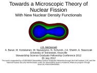
Magnetic Diagnostics for Equilibrium Reconstructions in the ...
Magnetic Diagnostics for Equilibrium Reconstructions in the ...
Magnetic Diagnostics for Equilibrium Reconstructions in the ...

Create successful ePaper yourself
Turn your PDF publications into a flip-book with our unique Google optimized e-Paper software.
<strong>Magnetic</strong> <strong>Diagnostics</strong> <strong>for</strong> <strong>Equilibrium</strong> <strong>Reconstructions</strong><br />
<strong>in</strong> <strong>the</strong> Presence of Non-axisymmetric Eddy Current<br />
Distributions <strong>in</strong> Tokamaks<br />
Laura Berzak, PPPL<br />
A.D. Jones, R. Kaita, T. Kozub, N. Logan, R.<br />
Majeski, J. Menard, L. Zakharov, PPPL<br />
LTX Team, PPPL
Outl<strong>in</strong>e<br />
2<br />
• Introduction to <strong>Magnetic</strong> Fusion Energy (MFE)<br />
• Overview of <strong>the</strong> Lithium Tokamak eXperiment (LTX)<br />
• <strong>Magnetic</strong> diagnostics <strong>for</strong> LTX<br />
• LTX LRDFIT – 2-D code characterization<br />
• LTX Cbshl – 3-D code development<br />
• Summary
Fusion Energy<br />
Goal: Generate power, like stars, through fusion reactions<br />
Example Reaction: D + T n + + 17.6 MeV<br />
Benefits:<br />
* Widely available <strong>in</strong>put fuel source – sea water<br />
* No risk of runaway cha<strong>in</strong> reaction lead<strong>in</strong>g to nuclear accident<br />
* Clean energy production – no greenhouse gas emission<br />
* No high-level radioactive, nuclear waste
<strong>Magnetic</strong> Fusion Energy<br />
* Fusion requires a balance of density, temperature, and conf<strong>in</strong>ement time<br />
* Required temperature too high <strong>for</strong> physical conta<strong>in</strong>ment magnetic bottle<br />
* Form a plasma <strong>in</strong>side a physical vacuum vessel<br />
* Constra<strong>in</strong> plasma particles to closed magnetic field l<strong>in</strong>es<br />
* Supply external heat<strong>in</strong>g <strong>in</strong> <strong>the</strong> <strong>for</strong>m of neutral beam <strong>in</strong>jection or<br />
radiofrequency heat<strong>in</strong>g<br />
* Highly energetic particles collide lead<strong>in</strong>g to fusion reactions and energy<br />
production<br />
* Several potential magnetic bottle ‘shapes’:<br />
Advanced Tokamak Spherical Torus Compact Stellarator
Lithium acts as a getter → reduc<strong>in</strong>g recycl<strong>in</strong>g<br />
1<br />
• Experimental confirmation of plasma per<strong>for</strong>mance enhancement with<br />
lithium usage:<br />
• TFTR lithium wall-condition<strong>in</strong>g – solid Li<br />
• T-11M, FTU lithium rail limiter – liquid Li<br />
• CDX-U tray limiter filled with 2000 cm 2 liquid lithium – liquid Li PFC<br />
CDX-U<br />
CDX-U tray limiter<br />
Red: Li, Blue: no Li<br />
Largest improvement <strong>in</strong> energy<br />
conf<strong>in</strong>ement time <strong>for</strong> an Ohmic<br />
tokamak
Lithium Tokamak eXperiment<br />
3<br />
• Extend previous lithium experimental results to operation with 85% liquid<br />
lithium coverage of last-closed-flux-surface<br />
LTX parameters:<br />
Major radius . . . . . . . . 0.4 m<br />
M<strong>in</strong>or radius . . . . . . . . 0.26 m<br />
Toroidal field . . . . . . . 2 kG<br />
Plasma current . . . . . . 15 kA 150 kA<br />
Discharge duration . . . 5 ms 25 ms<br />
1.8 m
LTX <strong>in</strong>-vessel, heated, con<strong>for</strong>mal Cu shell<br />
4<br />
• 85% LCFS covered by liquid lithium when shell is lithium-coated<br />
• Con<strong>for</strong>mal with plasma last-closed-flux surface<br />
• Two 22.5° toroidal breaks, and <strong>in</strong>board and outboard poloidal breaks<br />
• Can be heated up to 500 °C<br />
• Mechanically and electrically isolated from <strong>the</strong> vacuum vessel<br />
1.8 m
Basic <strong>the</strong>ory of magnetic diagnostics<br />
<br />
C<br />
E<br />
dl<br />
<br />
E dl<br />
E dl<br />
0 V<br />
<br />
B<br />
coil<br />
leads<br />
S<br />
<br />
ds<br />
V<br />
B <br />
<br />
S ds<br />
V<br />
0<br />
<br />
N<br />
RC<br />
<br />
NAB<br />
RC
LTX has extensive set of magnetic diagnostics<br />
5<br />
• 11 centerstack flux loops<br />
1.8 m<br />
• 16 shell flux loops<br />
• 4 saddle loops<br />
• 30 <strong>in</strong>-shell B-dot coils<br />
• 12 ex-shell B-dot coils<br />
• 18 2-axis gap B-dot coils<br />
• 26 B-dot coils <strong>in</strong> rectangular array<br />
• 2 plasma current-measur<strong>in</strong>g coils<br />
• 1 vessel current-measur<strong>in</strong>g coil<br />
• Plasma stored energy<br />
measurement<br />
Poloidal field coils
<strong>Magnetic</strong> diagnostics design requirements<br />
6<br />
• Withstand high temperatures (500 °C)<br />
contact with lithium<br />
• Ma<strong>in</strong>ta<strong>in</strong> electrical isolation between<br />
shell quadrants and between shell<br />
and vacuum vessel<br />
• M<strong>in</strong>imize distance between diagnostic<br />
and plasma<br />
• Provide data on toroidal asymmetries<br />
and<br />
• Provide full coverage of poloidal<br />
cross-section<br />
• Yield data <strong>for</strong> highly-constra<strong>in</strong>ed<br />
equilibrium flux surface<br />
reconstructions
Shell flux loops – 8 on upper shells, 8 on lower<br />
• 2-turn, center-tap grounded with separately grounded sta<strong>in</strong>less steel hous<strong>in</strong>g<br />
<strong>for</strong> noise immunity<br />
7<br />
• SS hous<strong>in</strong>g covered with Steatite ‘fishsp<strong>in</strong>e’ and MgO to provide electrical<br />
isolation between diagnostic and shell and between shell quadrants<br />
• Mounted directly to non-plasma fac<strong>in</strong>g side<br />
of shell to m<strong>in</strong>imize distance to plasma and<br />
provide full poloidal coverage<br />
• Signals valuable <strong>for</strong> code calibration, vertical<br />
null <strong>for</strong>mation, constra<strong>in</strong>ed equilibrium<br />
reconstructions
Saddle loops – 4 total; outboard of vertical midplane<br />
• Analogous materials and fabrication technique as shell flux loops<br />
8<br />
• Span toroidal gap, measure flux through gap from circulat<strong>in</strong>g shell currents<br />
• Signals essential <strong>for</strong> determ<strong>in</strong><strong>in</strong>g magnitude and evolution of shell currents
In- and ex-shell B-dot sensors<br />
• 30 <strong>in</strong>-shell, 12 ex-shell; outboard coverage <strong>in</strong>clud<strong>in</strong>g poloidal gap at 3<br />
toroidal locations<br />
9<br />
• Sensors mounted <strong>in</strong> SS hous<strong>in</strong>g to both plasma-fac<strong>in</strong>g side of shell and nonplasma-fac<strong>in</strong>g<br />
side of shell<br />
• Signals provide measure of field extremely close to plasma; evidence of<br />
toroidal asymmetries<br />
• Comparison between <strong>in</strong> and ex-shell sensors yields<br />
direct measurement of shell eddy currents
2-axis gap Mirnov coils – 9 probes upper, 9 lower<br />
• Total of 36 probes mounted <strong>in</strong> toroidal gap; provide full poloidal coverage<br />
10<br />
• Mount<strong>in</strong>g tabs plasma-sprayed with W; sensors covered by sta<strong>in</strong>less steel<br />
protective caps, leads covered with fiberglass and sta<strong>in</strong>less steel overbraid<br />
• Signals provide dense measurement of poloidal and radial fields with<br />
m<strong>in</strong>imal shell <strong>in</strong>fluence; yield measure of vertical<br />
field component and bulge of field <strong>in</strong>to toroidal gap
LTX LR circuit model with Data FITt<strong>in</strong>g capabilities<br />
• Axisymmetric (2-D), non-filamentary code developed <strong>for</strong> NSTX (J. Menard)<br />
– now tailored <strong>for</strong> LTX<br />
• Solves circuit equations based on models of vacuum vessel, shell and<br />
plasma composed of <strong>in</strong>dividual conduct<strong>in</strong>g elements with assigned<br />
<strong>in</strong>ductance and resistance values<br />
• To reduce 3-D effects to a 2-D representation – <strong>in</strong>board versus outboard<br />
shell elements’ resistivity values adjusted to account <strong>for</strong> different current<br />
path lengths<br />
‘Full Shell’ model<br />
11<br />
Z=0<br />
Z=0<br />
Shell<br />
Vacuum vessel<br />
‘No Shell’ model<br />
R<br />
R
LTX LRDFIT<br />
12<br />
‘No Shell’ model<br />
‘Full Shell’ model<br />
‘Partial Shell’ model<br />
‘Partial Shell’ model
LTX LRDFIT validation, comparison with fast camera<br />
17<br />
Visible fast camera frame<br />
Discharge <strong>in</strong>itiation
LTX LRDFIT field comparison at peak plasma current<br />
18<br />
Visible fast camera frame<br />
345.298 ms<br />
Discharge fully developed<br />
Peak I P
LTX LRDFIT field comparison at term<strong>in</strong>ation<br />
19<br />
Visible fast camera frame<br />
347.711 ms<br />
Discharge term<strong>in</strong>ation I P<br />
→ 0
Inherently 2-D, LTX LRDFIT can simulate 3-D circulat<strong>in</strong>g shell currents<br />
13<br />
0.0 0.8<br />
60<br />
1.5E-3<br />
0.4<br />
Simulated current (kA)<br />
0<br />
0.0<br />
Saddle loop flux (Wb)<br />
-20<br />
0.05<br />
Time (s)<br />
-5E-3<br />
1.5E-3<br />
-0.4<br />
Field (T)<br />
Flux (Wb)<br />
0.00<br />
0.0<br />
-0.01<br />
0.44 0.46 0.48<br />
-3E-3
Shell currents act as additional set of PF coils<br />
• Shell currents dur<strong>in</strong>g plasma discharge ~20 kA<br />
14<br />
• Provide field <strong>in</strong> opposite direction to ma<strong>in</strong> vertical field coils, elongates<br />
plasma, drives vertically unstable<br />
• Up-down asymmetry observed on magnetic<br />
diagnostics signals<br />
• Plasma reconstructions show solution high or<br />
low <strong>in</strong> plasma volume<br />
(Wb)<br />
0.004<br />
0.002<br />
0.000<br />
-0.002<br />
-0.004 Shell flux comparison<br />
0.444 0.446 0.448<br />
Time (s)<br />
(T)<br />
0.010<br />
0.005<br />
0.000<br />
-0.005<br />
-0.010<br />
-0.015 In-shell comparison<br />
0.444<br />
0.446<br />
0.448<br />
Time (s)
Next step: 3-D simulation of LTX double-walled conduct<strong>in</strong>g structure<br />
• Response function technique (L. Zakharov) coupled with three-dimensional<br />
electromagnetic model and circuit equations<br />
• Response functions – ma<strong>the</strong>matical relationship between a f<strong>in</strong>ite-size<br />
sensor and an <strong>in</strong>dividual poloidal field coil through driv<strong>in</strong>g voltage<br />
applied to <strong>the</strong> field coil:<br />
S(<br />
t)<br />
Signals<br />
<br />
<br />
B(<br />
t)<br />
B(<br />
t)<br />
<br />
<br />
<br />
t<br />
t<br />
0<br />
R(<br />
t<br />
R(0)<br />
V ( t)<br />
Spl<strong>in</strong>e<br />
<br />
) V (<br />
) d<br />
<br />
<br />
tt<br />
0<br />
0<br />
R(<br />
) V<br />
t<br />
( t<br />
<br />
) d<br />
20<br />
Response func.
Response Function Technique<br />
• Calibrate location of field coils and magnetic diagnostics by m<strong>in</strong>imiz<strong>in</strong>g<br />
difference between <strong>the</strong>oretical saturation value and calculated asymptote<br />
from measured data response function<br />
Shell flux loop #8 Response Functions<br />
21<br />
S(<br />
t) |<br />
tt<br />
<br />
0<br />
<br />
T<br />
T<br />
0<br />
R(<br />
T)<br />
V ( t T)<br />
R(<br />
) V<br />
t<br />
( t <br />
) d<br />
Value (arbitrary unit)<br />
• Matrix of response functions allows:<br />
Time <br />
• Non-plasma contribution to sensor signals to be removed<br />
• ‘Reverse’ solv<strong>in</strong>g <strong>for</strong> discharge design
Coupled with response functions, simulate eddy currents <strong>in</strong> shell and vessel<br />
• Triangular mesh calculated <strong>for</strong> shell quadrants and vacuum vessel<br />
(>18,000 elements per shell quadrant, >8,000 elements <strong>for</strong> vacuum<br />
vessel)<br />
22<br />
• Derived (L. Zakharov): analytical representation<br />
of field due to <strong>the</strong> surface current on each triangle,<br />
no surface s<strong>in</strong>gularities AND l<strong>in</strong>ked circuit equations –<br />
<br />
iT<br />
ia<br />
<br />
<br />
0.1<br />
<br />
jN<br />
T<br />
<br />
j0<br />
<br />
Eij<br />
i<br />
<br />
ext ( I<br />
a cb<br />
I<br />
b ac<br />
I<br />
c ba)<br />
i i<br />
( I<br />
r r r<br />
n)<br />
<br />
<br />
j<br />
A<br />
rcb<br />
0<br />
i<br />
(2Sd<br />
)<br />
i
Conclusions<br />
• Extensive need to diagnose eddy currents and 3-D effects, particularly as<br />
more experiments <strong>in</strong>vestigate alternative first wall and blanket concepts<br />
23<br />
• LTX magnetic diagnostics system permits quantification of eddy currents,<br />
provides path <strong>for</strong>ward <strong>for</strong> mitigat<strong>in</strong>g operational issues <strong>in</strong>troduced<br />
• LTX LRDFIT has been tailored to <strong>in</strong>clude 3-D effects, essential <strong>for</strong> start-up<br />
design and discharge development<br />
• Fur<strong>the</strong>r work: cont<strong>in</strong>ued development of a full, 3-D electromagnetic code<br />
• Double-walled conduct<strong>in</strong>g structure (shell and vacuum vessel) of LTX<br />
provides opportunity to explore liquid lithium PFCs and to develop<br />
magnetic diagnostics, 2-D, and 3-D codes of general applicability <strong>for</strong>:<br />
quantify<strong>in</strong>g eddy currents and <strong>the</strong>ir effects on plasma behavior, and<br />
optimiz<strong>in</strong>g <strong>the</strong>se effects
Acknowledgements<br />
I would like to s<strong>in</strong>cerely thank my <strong>the</strong>sis advisors, Robert Kaita and Richard<br />
Majeski, <strong>for</strong> <strong>the</strong> opportunity to be part of <strong>the</strong> LTX team and <strong>for</strong> all of <strong>the</strong>ir<br />
patience, time, and guidance.<br />
I would like to thank <strong>the</strong> LTX team as well <strong>for</strong> <strong>the</strong>ir support and help<br />
throughout my <strong>the</strong>sis work.<br />
I would also like to thank <strong>the</strong> terrific people at Krell <strong>for</strong> all of <strong>the</strong>ir help and <strong>for</strong><br />
<strong>the</strong> opportunity to be part of <strong>the</strong> SSGF program.
<strong>Magnetic</strong> diagnostics crucial <strong>for</strong> discharge development<br />
15<br />
• Basic Ohmically-driven tokamak start-up <strong>the</strong>ory:<br />
• Provide Ohmic flux to drive plasma<br />
• Form vertical/poloidal field null near<br />
peak <strong>in</strong> Ohmic flux sw<strong>in</strong>g<br />
• Provide vertical field <strong>for</strong> conf<strong>in</strong>ement<br />
after <strong>in</strong>itial electron avalanche and<br />
breakdown<br />
• Develop vertical fields <strong>for</strong> discharge<br />
control and shap<strong>in</strong>g<br />
Shell flux loop subtraction<br />
• Challenges <strong>in</strong> double-walled tokamak:<br />
• M<strong>in</strong>imiz<strong>in</strong>g required Ohmic flux<br />
• Quantify<strong>in</strong>g eddy currents <strong>in</strong> conductive structures close to plasma
Quantify<strong>in</strong>g eddy currents <strong>in</strong> <strong>the</strong> shell<br />
• Calculation of decay times<br />
16<br />
• Collect library of calibration shots: <strong>in</strong>dividual poloidal field coil pulses<br />
and pulses with operational pairs of coils, long-pulse (>300 ms)<br />
wherever possible<br />
• Expand library with poloidal field coil-only pulses dur<strong>in</strong>g shell heat<strong>in</strong>g<br />
tests
Supplemental Slides
Supplemental Slides<br />
• Ma<strong>the</strong>matically l<strong>in</strong>early superimpose poloidal fields to m<strong>in</strong>imize vertical<br />
field near loop voltage peak<br />
<br />
i1<br />
) 0<br />
• Compare with LTX LRDFIT field contour simulations<br />
6<br />
A I(<br />
t<br />
<br />
i<br />
t i
Future Work – Interpretation of <strong>Reconstructions</strong><br />
• Use reconstructions to study energy conf<strong>in</strong>ement time<br />
• Exam<strong>in</strong>e changes <strong>in</strong> current profile with reduced recycl<strong>in</strong>g<br />
• Exam<strong>in</strong>e scal<strong>in</strong>g of conf<strong>in</strong>ement time with various plasma<br />
parameters such as current, field, density, and temperature<br />
• Compare results with ASTRA-ESC simulations<br />
• Simulations utilize <strong>the</strong> Reference Transport Model (RTM), which<br />
reflects elim<strong>in</strong>ation of anomalous electron transport <strong>in</strong> LiWall<br />
regime, and fits well with CDX-U data<br />
• RTM is sensitive to diffusion coefficients, not <strong>the</strong>rmoconduction<br />
s<strong>in</strong>ce only m<strong>in</strong>imized temperature gradient is present – electron and<br />
ion transport become l<strong>in</strong>ked: e = i = D i,e = i<br />
neoclassical<br />
• Compare simulations with LTX data and reconstructions<br />
• If similar correspondence is observed, may permit first pr<strong>in</strong>ciples<br />
transport model of LTX