Download - legrand
Download - legrand
Download - legrand

You also want an ePaper? Increase the reach of your titles
YUMPU automatically turns print PDFs into web optimized ePapers that Google loves.
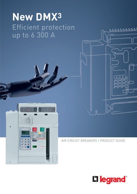
New DMX 3<br />
Efficient protection<br />
up to 6 300 A<br />
AIR CIRCUIT BREAKERS | PRODUCT GUIDE
NEW DMX 3 ACBs<br />
UP TO 6 300 A<br />
EFFICIENT PROTECTION<br />
AND CONTROL FOR ALL<br />
TYPE OF BUILDINGS<br />
DMX 3 AIR CIRCUIT BREAKERS
Electrical panel<br />
equipped ped with<br />
DPX MCCBs and<br />
modular MCBs<br />
up to 1 600 A<br />
Electrical panel<br />
equipped with<br />
DPX MCCBs and<br />
modular MCBs<br />
up to 1<br />
600 A<br />
Main electrical<br />
panel equipped<br />
with DMX 3 ACBs<br />
and DPX MCCBs<br />
up to 4<br />
000 A<br />
Thanks to DPX range<br />
of MCCBs and to<br />
DX MCBs you<br />
can benefit of the advantages<br />
of a complete protection system<br />
at any level of<br />
the installation<br />
DMX 3 AIR CIRCUIT BREAKERS<br />
01
Draw-out DMX 3<br />
Key locking<br />
in “Open” position<br />
Open control button<br />
MP4 LSIg<br />
tripping unit<br />
Reset button<br />
Indicator showing<br />
the position<br />
of the main<br />
contacts O / I<br />
Isolator terminal blocks<br />
for auxiliary contacts<br />
Windows for displaying<br />
auxiliary equipment<br />
Close control button<br />
Colour marking<br />
for breaking capacity:<br />
-Grey for DMX 3 N<br />
-Yellow for DMX 3 H<br />
Indicator showing<br />
the load status of springs:<br />
Charged / Discharged<br />
Spring loading lever<br />
Key locking in<br />
drawn-out position<br />
Device position<br />
indicator :<br />
- Pluged in<br />
- TEST<br />
- Drawn-out<br />
Lockable aperture<br />
for insertion of the<br />
extraction handle<br />
Optimized performance<br />
up to 6 300 A<br />
DMX 3 AIR C IRC UIT BREAKERS<br />
| DMX 3 air circuit breakers and DMX 3 -I isolating switches are available<br />
in three frame sizes. Three breaking capacities for circuit breakers:<br />
50 kA for the DMX 3 -N designation 65 kA for DMX 3 -H and 100 kA for DMX 3 -L.<br />
| The range covers 10 rated currents, between 800 A and 6 300 A.<br />
| All range of DMX 3 air circuit breakers and DMX 3 -I isolating switches<br />
is available in fixed and draw-out version.<br />
02
BREAKING CAPACITIES AND RATED CURRENTS<br />
800 A 1 000 A 1 250 A 1 600 A 2 000 A 2 500 A 3 200 A 4 000 A 5 000 A 6 300 A<br />
DMX 3 -N<br />
DMX 3 -H<br />
50 kA | FIXED/DRAW-OUT<br />
65 kA | FIXED/DRAW-OUT<br />
DMX 3 -L 100 kA | FIXED/DRAW-OUT 100 kA | F/D-O<br />
OVERAL DIMENSIONS AND WEIGHT<br />
Fixed version<br />
Height Depth Width Weight (1)<br />
FRAME 1:<br />
DMX 3 -N 2500<br />
DMX 3 -H 2500<br />
FRAME 2:<br />
DMX 3 -L 2500<br />
DMX 3 -N/H/L<br />
4000<br />
FRAME 3:<br />
DMX 3 -L 6300<br />
3P 419 mm 354 mm 273 mm 41 kg<br />
4P 419 mm 354 mm 358 mm 48 kg<br />
3P 419 mm 354 mm 408 mm 59 kg<br />
4P 419 mm 354 mm 538 mm 76 kg<br />
3P 419 mm 354 mm 797 mm 118 kg<br />
4P 419 mm 354 mm 1064 mm 152 kg<br />
Draw-out version<br />
Height Depth Width Weight (1)<br />
FRAME 1:<br />
DMX 3 -N 2500<br />
DMX 3 -H 2500<br />
3P 465 mm 433 mm 327 mm 77 kg<br />
4P 465 mm 433 mm 412 mm 94 kg<br />
FRAME 2:<br />
DMX 3 -L 2500<br />
DMX 3 -N/H/L<br />
4000<br />
3P 465 mm 433 mm 425 mm 108 kg<br />
4P 465 mm 433 mm 555 mm 137 kg<br />
FRAME 3:<br />
DMX 3 -L 6300<br />
3P 465 mm 433 mm 804 mm 216kg<br />
4P 465 mm 433 mm 1064 mm 274 kg<br />
(1) For trip-free switches, please consult us<br />
LEGRAND ADVANTAGE<br />
The overal dimensions of the breaker contribute considerably to an efficient use of the space inside<br />
the electrical panel. The constant depth for all the rated currents facilitates connection of the busbars.<br />
OTHER ELECTRICAL FEATURES<br />
Rated operational voltage Ue: 690 Vac 50/60 Hz<br />
Rated insulation voltage Ui: 1 000 Vac 50/60 Hz<br />
Rated impulse withstand voltage Uimp: 12 kV<br />
Category of use: B<br />
Ambient temperature: - 5 °C to 70 °C<br />
Humidity: + 55 °C with relative humidity of 95%,<br />
conforms to IEC 68-2-30<br />
DMX 3 AIR CIRCUIT BREAKERS<br />
03
MP4 LSIg<br />
electronic<br />
protection unit<br />
Ig settings<br />
tg settings<br />
Ii settings<br />
tm settings<br />
Im settings<br />
Ir settings<br />
LEDs indicating<br />
correct operation<br />
tr settings<br />
Mini USB connector<br />
to PC for testing<br />
Neutral<br />
protection<br />
Precise & user friendly<br />
LCD tripping units<br />
DMX 3 AIR C IRC UIT BREAKERS<br />
| Besides their easy mounting and connection, strength and good<br />
continuity of operation, 3 types of electronic units allow precise adjustment of different limits<br />
for current values and time delay. The result is an efficient protection against electrical faults<br />
while maintaining total discrimination with downstream breakers.<br />
| The LCD display lets you monitor the measured current values and informs you on fault<br />
adjustement and log (the cause of last trip and maintenance operations).<br />
04
MP4 LI ELECTRONIC PROTECTION UNIT CAT. N° 288 00<br />
The following settings are adjusted<br />
using rotary selector switches:<br />
t<br />
Ir<br />
• Long time delay protection against overloads: Ir<br />
• Long delay protection operation time: tr<br />
• Instantaneous protection against very high short circuits: Ii<br />
• Neutral protection: IN<br />
t r<br />
Ii<br />
I<br />
MP4 LSI ELECTRONIC PROTECTION UNIT CAT. N° 288 01<br />
The following settings are adjusted<br />
using rotary selector switches:<br />
t<br />
• Long time delay protection against overloads: Ir<br />
• Long delay protection operation time: tr<br />
• Short time delay protection against short circuits: Im<br />
• Short time delay protection operation time: tm<br />
• Instantaneous protection against very high short circuits: Ii<br />
• Neutral protection: IN<br />
Ir<br />
Im Ii I<br />
t r<br />
t m<br />
MP4 LSIg ELECTRONIC PROTECTION UNIT CAT. N° 288 02<br />
t<br />
t g<br />
using rotary selector switches:<br />
• Long time delay protection against overloads: Ir<br />
• Long delay protection operation time: tr<br />
• Short time delay protection against short circuits: Im<br />
• Short time delay protection operation time: tm<br />
• Instantaneous protection against very high short circuits: Ii<br />
• Earth fault current: Ig<br />
• Time delay on earth fault tripping: tg<br />
• Neutral protection: IN<br />
t<br />
Ir<br />
t r I g<br />
I<br />
Im Ii I<br />
t m<br />
LEGRAND ADVANTAGE<br />
All protection units are equipped with batteries so you can monitor the parameters<br />
even when the breaker is not connected.<br />
INFORMATION<br />
All DMX 3 breakers are factory equipped with any MP4 protection unit LI, LSI or LSIg according<br />
to your requirements. You just need to select and indicate the 2 catalogue numbers when placing<br />
the order (1 for the breaker and 1 for the tripping unit).<br />
DMX 3 AIR CIRCUIT BREAKERS<br />
05
Colour<br />
touch screen<br />
Settings lock<br />
LEDs indicating correct<br />
operation, pre-alarm<br />
and alarm for overload<br />
and temperature<br />
Mini USB port<br />
for PC connection<br />
ON button<br />
DMX 3 AIR C IRC UIT BREAKERS<br />
Innovative & user friendly<br />
touch screen tripping units<br />
| MP6 electronic protection units are equipped with a colour touch screen, particularly user friendly,<br />
thanks to intuitive icon-based navigation system. The colour display provides a clear presentation<br />
of the parameters of the installation.<br />
| Touch screen protection units integrate all the functions of LCD tripping units and have<br />
an advanced measurement function which, in addition to monitoring currents, can also be used<br />
to display voltages, active and reactive powers, frequency, power factor, and also energy.<br />
| Alarms can be programmed on a number of these parameters: max. voltage, min. voltage,<br />
voltage imbalance, max. and min. frequency, etc.<br />
06
MP6 LSI TOUCH SCREEN PROTECTION UNIT CAT.NO 288 03<br />
The following settings are adjusted using the touch screen:<br />
• Long time delay protection against overloads: Ir<br />
• Long delay protection operation time: tr<br />
• Short time delay protection against short circuits: Im<br />
• Short time delay protection operation time: tm<br />
• Instantaneous protection against very high short circuits: Ii<br />
• Neutral protection: N<br />
t<br />
Ir<br />
Im Ii I<br />
t r<br />
t m<br />
Tripping curve<br />
preview<br />
MP6 LSIG TOUCH SCREEN PROTECTION UNIT CAT.NO 288 04<br />
The following settings are adjusted using the touch screen:<br />
t<br />
t g<br />
• Long time delay protection against overloads: Ir<br />
• Long delay protection operation time: tr<br />
• Short time delay protection against short circuits: Im<br />
• Short time delay protection operation time: tm<br />
• Instantaneous protection against very high short circuits: Ii<br />
• Earth fault current: Ig<br />
• Time delay on earth fault tripping: tg<br />
• Neutral protection: N<br />
t<br />
Ir<br />
t r I g<br />
I<br />
Im Ii I<br />
t m<br />
Earth fault tripping<br />
curve preview<br />
LEGRAND ADVANTAGE<br />
The icon-based interface of the management software and the innovative touch screen technology<br />
used for MP6 tripping units simplify setting and preparing operations of the DMX³ circuit breaker.<br />
INFORMATION<br />
The MP4 and MP6 electronic protection units can communicate via an RS-485 port.<br />
This port is used for remote monitoring and management of the devices in the installation,<br />
using the MODBUS protocol. It is therefore possible to control circuit breaker opening and closing,<br />
display the electrical parameters and detect all the alarms generated by each device, from a PC.<br />
3 AIR CIRCUIT BREAKERS<br />
07
STARTING MENU<br />
This menu displays the values of I 1, I 2, I 3 and I N as a diagram, the date<br />
and the hour, and the alarm icon.<br />
If the breaker opens following an electrical fault a specific icon will appear<br />
on the upper part of the screen.<br />
Pressing this icon will open a new window showing the cause of the last event.<br />
Other possible actions:<br />
• Right arrow icon: access the main menu<br />
• Alarm icon: preview the cause of the alarm in course<br />
MAIN MENU<br />
1 5<br />
2 6<br />
3<br />
7<br />
The main menu allows accessing different windows for setting different parameters<br />
of the breaker or previewing measured values, battery status, tripping history, etc.<br />
The following accesses are possible:<br />
1 Setting according to the tripping curves (current and time)<br />
2 Access tripping unit settings (luminosity, contrast and sound volume)<br />
3 Access to general information of the breaker<br />
4 Back to the previous page<br />
5 Access measured values menu<br />
6 Access archives<br />
7 Preview battery charging status<br />
4<br />
Innovative & user friendly touch<br />
screen tripping units (continued)<br />
DMX 3 AIR C IRC UIT BREAKERS<br />
| MP6 electronic protection units collect all the useful information in 5 sections,<br />
each one easily reachable via the main menu in order to allow an efficient control.<br />
Navigation through these sections is very simple thanks to the arrows at the bottom of each page.<br />
| MP6 electronic protection units have an intuitive graphical interface. All useful information<br />
and selected settings are easy to understand and visible at a glance. For example current values<br />
can be visualized on the starting page thanks to a histogram. Different other settings<br />
can be simultaneously displayed on the "settings" screen in order to have a global view.<br />
08
PROTECTIONS SETTING MENU<br />
Vertical arrows allow scrolling between<br />
different electrical parameters:<br />
Ii, Im, tm, Ir, tr, Ig, tg, etc.<br />
Pressing horizontal icons gives access<br />
to corresponding windows allowing value<br />
settings. Each value can be increased/<br />
decreased, validated or suppressed.<br />
The values need to be saved into memory<br />
at the end of the process, for each setting.<br />
MEASURED VALUES MENU<br />
This window allows previewing<br />
of measured values for:<br />
• Currents<br />
• Voltages (Ph/N and Ph/Ph)<br />
• Active and reactive powers<br />
• Power factor (total and per phase)<br />
• Active and reactive energy<br />
• Harmonics ( for currents and voltages )<br />
Pressing I, m, M and avg icons at the bottom<br />
of the window will display respectively:<br />
instantaneous, minimum, maximum<br />
and average value of electrical parameters.<br />
INFORMATION<br />
• The following events<br />
and values are registered into<br />
memory and can be accessed<br />
via specific menu:<br />
cause of the last event, event<br />
counter, events history with<br />
date and hour, alarms<br />
history with date and hour<br />
• MP6 tripping units allow<br />
following application:<br />
logical selectivity, management<br />
of non priority loads, contact<br />
management (with Cat.No 288 12)<br />
• MP6 tripping units allow<br />
following alarms:<br />
power reverse, current<br />
imbalance, maximum<br />
and minimum voltage values<br />
U1N, U2N, U3N, maximum<br />
currents I1, I2, I3, voltage<br />
imbalance (phaseneutral),<br />
inversed phase<br />
rotation,maximum and<br />
minimum frequency values.<br />
DMX 3 AIR CIRCUIT BREAKERS<br />
09
Undervoltage release<br />
Shunt trip<br />
Closing coil<br />
Motor operators<br />
Fast clipping control<br />
accessories<br />
DMX 3 AIR C IRC UIT BREAKERS<br />
| You can remotely control the DMX 3 thanks to its range of accessories:<br />
shunt trips, undervoltage releases, motor operators and closing coils.<br />
| All the control accessories are simply clipped on to the front panel of the circuit breaker,<br />
which is especially configured in order to facilitate the clipping.<br />
| Every type of accessory is compatible with its own location, in order to avoid any possible mistake.<br />
10
All control accessories can be easily installed without any special tool and in a very short time.<br />
The installation is to be done on the front panel of the air circuit breaker. In that way, the separation<br />
between power and control circuits is guaranteed.<br />
SHUNT TRIP<br />
Shunt trips are devices used for the remote<br />
instantaneous opening of the air circuit<br />
breaker. They are generally controlled trough<br />
an N/O type contact. The actual offer of shunt<br />
trips proposes different supply voltages<br />
(from 24 V to 415 V), compatibles with AC<br />
and DC currents. The shunt trips are already<br />
equipped with a special fast connector, to be<br />
directly inserted into auxiliary contacts block.<br />
An auxiliary contact is connected in series<br />
with the coil, cutting off its power supply<br />
when the main poles are open.<br />
Technical characteristics:<br />
• Nominal voltage Un: 24 VA to 480 VA and<br />
from 24 V= to 250 V=<br />
• Tolerance on nominal voltage:<br />
70 to 110% Vn<br />
• Maximum power consumption<br />
(max.power for 180 ms): 500 VAA/500 W =<br />
• Continuous power: 5 VAA/5 W =<br />
• Maximum opening time: 30 ms<br />
• Insulation voltage: 2 500 V 50 Hz for 1min<br />
• Endurance on pulse: surge proof<br />
4 kV 1.2/50 μs<br />
UNDERVOLTAGE RELEASE<br />
Undervoltage releases are devices which are<br />
generally controlled by an N/C type contact.<br />
The trigger instantaneous opening of the<br />
circuit breaker if their supply voltage drops<br />
below a certain threshold and in particular<br />
if the control contact opens. These releases<br />
are equipped with a device for limiting their<br />
consumption after the circuit has been<br />
closed.<br />
Technical characteristics:<br />
• Nominal voltage Un: 24 VA to 480 VA<br />
and from 24 V= to 250 V=<br />
• Tolerance on nominal voltage:<br />
85 to 110% Vn<br />
• Maximum power consumption<br />
(max.power for 180 ms): 500 VAA/500 W =<br />
• Continuous power: 5 VAA/5 W =<br />
• Opening time: 60 ms<br />
• Insulation voltage: 2 500 V 50 Hz for 1min<br />
• Endurance on pulse: surge proof<br />
4 kV 1.2/50 μs<br />
CLOSING COILS<br />
These coils are used for remotely controlling<br />
the closing of the power contacts of the<br />
circuit breaker. The springs of the circuit<br />
breaker are to be loaded prior to the action<br />
of the closing coils. They are controlled by<br />
an N/O type contact.<br />
Technical characteristics:<br />
• Nominal voltage Un: 24 VA to 480 VA<br />
and from 24 V= to 250 V=<br />
• Tolerance on nominal voltage:<br />
70 to 110% Vn<br />
• Maximum power consumption<br />
(max.power for 180 ms): 500 VAA/500 W =<br />
• Continuous power: 5 VAA/5 W =<br />
• Maximum closing time: 50 ms<br />
• Insulation voltage: 2 500 V 50 Hz for 1min<br />
• Endurance on pulse: surge proof<br />
4 kV 1.2/50 μs<br />
LEGRAND ADVANTAGE<br />
Electrical connection is made in no time thanks to the fast connector supplied<br />
on all above accessories.<br />
NUMBER OF CONTROL AUXILIARIES FOR DMX 3 = 3<br />
Shunt trip: 1<br />
Undervoltage release: 1<br />
Closing coils: 1<br />
DMX 3 AIR CIRCUIT BREAKERS
MOTOR OPERATORS<br />
Motor operators, are used for remotely reloading the<br />
springs of the circuit breaker mechanism immediately<br />
after the device closes. The device can thus be re-closed<br />
almost immediately after an opening operation.<br />
To motorise a DMX 3 it is necessary to add a release coil<br />
(undervoltage release or shunt trip) and a closing coil.<br />
If the supply voltage of the controls fails, it is still<br />
possible to reload the springs manually. Motor-driven<br />
controls have “limit switch” contacts which cut off the<br />
power supply of their motor after the springs have been<br />
reloaded. Motor operators are easy to mount, with only<br />
three screws.<br />
Technical characteristics:<br />
• Nominal voltage Un: from 24 VA<br />
to 480 VA and from 24 V= to 250 V=<br />
• Tolerance on nominal voltage:<br />
85 to 110% Vn<br />
• Spring reloading time: 7s<br />
• Maximum power consumption:<br />
240 VAA/240 W =<br />
• Starting current: 2 up to 3 x In for<br />
about 80 ms<br />
• Maximum cycle: 1/min<br />
SAFETY AND PADLOCKING ACCESSORIES FOR AN INCREASED SECURITY<br />
The DMX 3 circuit breakers draw-out types are delivered as standard with safety padlocking shutters<br />
preventing access to live terminals. They have a number of other safety devices, such as:<br />
• Key-operated locks:<br />
Main contacts open<br />
Circuit breaker in draw-out position<br />
• Padlocks for:<br />
Main contacts open<br />
Contact shutters closed (for draw-out position)<br />
• Door locking in order to prevent the opening<br />
of the electrical switchboard door when<br />
the contacts of the ACB are closed.<br />
Fixed version equipped with padlocking system<br />
Draw-out version equipped with key-operated locks<br />
Easy identification<br />
of control accessories<br />
DMX 3 AIR C IRC UIT BREAKERS<br />
| Electrical auxiliaries are connected on the front panel on terminal blocks<br />
provided for this purpose. Accessories are identified on the front panel.<br />
| As the cover has window, it is easy to ascertain, which devices are fitted on the circuit breaker.<br />
12
FRONT PANEL CONNECTION TERMINAL BLOCK<br />
The terminal block of DMX³ ACBs offers the possibility to connect a trip contact, up to 10 auxiliary contacts and<br />
diffrent other control and singalling functions<br />
Standard<br />
trip contact<br />
Standard<br />
auxiliary contacts<br />
Dedicated connector for :<br />
- 24 V DC external auxiliary<br />
power supply Cat.No 288 06<br />
- Programmable contact module<br />
Cat.No 288 12<br />
- Supervision serial port (if the<br />
ACB is equipped with communication<br />
option Cat.No 288 05)<br />
Dedicated connector for :<br />
- External neutral<br />
Cat.No 288 11<br />
Dedicated connector for :<br />
- Local programmable relay<br />
( 4 A Vmax 230 V a.c.)<br />
NUMBER OF AUXILIARY CONTACTS FOR DMX 3 = 10<br />
4 auxiliary contacts as standard (NO/NC)<br />
6 additional auxiliary contacts (NO/NC)<br />
DMX 3 AIR CIRCUIT BREAKERS<br />
13
FIXED VERSION-CHOOSE YOUR CONNECTION ACCESSORIES: 3 POSSIBILITIES<br />
The type of rear terminals<br />
can be easily changed according to your needs.<br />
REAR TERMINALS FOR FLAT CONNECTION<br />
Frame 1:<br />
3P: Cat. N°. 288 84<br />
4P: Cat. N°. 288 85<br />
Frame 2:<br />
3P: Cat. N°. 288 92<br />
4P: Cat. N°. 288 93<br />
Frame 3:<br />
3P: Cat. N°. 288 92 x 2<br />
4P: Cat. N°. 288 93 x 2<br />
REAR TERMINALS FOR VERTICAL CONNECTION<br />
This type of connection uses 2 accessories:<br />
the previous rear terminals for flat connection,<br />
which must be equipped with the vertical ones.<br />
+<br />
Frame 1: Frame 2 and 3 (1) :<br />
3P: Cat. N°. 288 84 + 288 82 3P: Cat. N°. 288 92 + 288 94<br />
4P: Cat. N°. 288 85 + 288 83 4P: Cat. N°. 288 93 + 288 95<br />
(1) For frame 3 the quantity is multiplied by 2<br />
The breaker is supplied with rear<br />
terminals for horizontal connection<br />
SPREADERS<br />
For any situation requiring a bigger width<br />
for a safe connection (i.e. aluminium bus bars).<br />
Frame 1:<br />
3 types of accessories<br />
- For flat connection<br />
3P: Cat. N°. 288 86<br />
4P: Cat. N°. 288 87<br />
- For vertical connection<br />
3P: Cat. N°. 288 88<br />
4P: Cat. N°. 288 89<br />
- For horizontal connection<br />
3P: Cat. N°. 288 90<br />
4P: Cat. N°. 288 91<br />
DMX 3 AIR C IRC UIT BREAKERS<br />
Connection:<br />
maximum adaptability<br />
| The fixed version of DMX 3 is equipped with rear terminals for horizontal connection with bars.<br />
| You can change connection type according to your needs.<br />
14
DMX 3 AIR CIRCUIT BREAKERS<br />
15
DRAW-OUT VERSION-CHOOSE YOUR CONNECTION ACCESSORIES<br />
Draw-out version of the DMX 3 breakers is supplied<br />
with rear terminals for flat connection with bars.<br />
You can easily transform those terminals into<br />
vertical or horizontal type by using the unique<br />
reversible connector.<br />
2 TYPES OF FIXING<br />
Reversible connector for vertical or ...<br />
... horizontal connection.<br />
Frame 1:<br />
3P: Cat. N°. 288 96<br />
4P: Cat. N°. 288 97<br />
Frame 2:<br />
3P: Cat. N°. 288 94<br />
4P: Cat. N°. 288 95<br />
Frame 3:<br />
3P: Cat. N°. 288 94 x 2<br />
4P: Cat. N°. 288 95 x 2<br />
The breaker is supplied with rear<br />
terminals for flat connection<br />
FLAT CONNECTION USING THE REAR<br />
TERMINALS OF THE BREAKER<br />
DMX 3 AIR C IRC UIT BREAKERS<br />
Connection:<br />
maximum adaptability (continued)<br />
| The draw-out version is equipped with rear terminals for flat connection with bars.<br />
16
DRAW-OUT VERSION: EXAMPLES OF CONNECTIONS<br />
Draw-out version of the DMX 3 breakers is supplied with rear terminals for flat connection with bars.<br />
You can easily transform those terminals into vertical or horizontal type by using the unique reversible connector.<br />
CONNECTIONS: A FEW RECOMMENDATIONS !<br />
Connections provide the electrical connection of equipment and are also responsible<br />
for a considerable proportion of their heat dissipation.<br />
Connections must never be under-sized.<br />
Plates or terminals must be used over a maximum area.<br />
Heat dissipation is encouraged by arranging the bars vertically. If an uneven number<br />
of bars is connected, place the higher number of bars on the upper part of the terminal.<br />
Avoid bars running side by side: this causes poor heat dissipation and vibrations.<br />
Place spacers between the bars to maintain a distance between them which<br />
is at least equivalent to their thickness.<br />
DMX 3 AIR CIRCUIT BREAKERS<br />
17
Led alarm (if red)<br />
Voltage<br />
value display<br />
Led voltage presence<br />
(red = voltage present)<br />
Opening/Closing<br />
circuit breakers<br />
line Main/Sec<br />
Led circuit breaker status<br />
opened (=green) or closed (=red)<br />
Led circuit breaker<br />
not inserted (=red)<br />
Led electronic control<br />
box suplly (OK if green)<br />
Led electronic control box order:<br />
circuit breaker closing (=red)<br />
circuit breaker opening (=green)<br />
AUTOMATIC mode<br />
MANUAL mode<br />
Led circuit<br />
breaker tripped (=red)<br />
DMX 3 AIR C IRC UIT BREAKERS<br />
Continuity of service<br />
and increased safety<br />
| Supply invertors answer the double need of continuity of service and greater safety (security).<br />
Traditionally used in hospitals, public buildings, industries with continuous manufacturing<br />
processes, airports and military applications, supply invertors become increasingly required for new<br />
applications such as telecommunications and computing treatment or in the management of energy<br />
sources, notably those say “renewable energies”.<br />
18
AUTOMATIC SUPPLY INVERTORS<br />
All DMX 3 air circuit breakers (fixed and draw-out version) can be fitted<br />
with an interlocking system which guarantees “mechanical safety”<br />
in the event of supply inversion. Interlocking is achieved using a cable<br />
system and interlocking units mounted on each circuit breaker.<br />
Every circuit breaker composing the supply invertor must be equipped<br />
with one interlocking unit.<br />
This system allows devices of different sizes and types (3P, 4P, fixed,<br />
draw-out) to be interlocked. DMX 3 devices can be installed in different<br />
configurations inside the enclosure.<br />
This mechanical interlocking system can be supplemented<br />
by motorised operators and an automation control unit making<br />
the invertor fully automatic.<br />
The Legrand automatic control unit Cat.N° 261 93 allows to easily<br />
manage the automatic switching of two sources.<br />
Controlled by a microprocessor, the unit is fully programmable.<br />
All the parameters are adjustable: values of the thresholds of tension,<br />
temporization between switching, starting up of a generator …<br />
Control panel of a supply invertor with<br />
automation control unit Cat. N° 261 93<br />
Umain: present<br />
Usec: absent<br />
Q1: closed<br />
Q2: open<br />
Q1: closed<br />
Umain: absent<br />
Temporization S1: 0,5 to 120s<br />
Temporization SC: 0,1 to 10s<br />
Q2: open<br />
yes<br />
no<br />
Umain: absent?<br />
Umain: present?<br />
no<br />
yes<br />
Temporization SC1: 3 to 120s<br />
Q1: open<br />
Temporization S: 0,5 to 120s<br />
Back to normal<br />
Umain: present<br />
no<br />
Usec present?<br />
yes<br />
Q2: closed<br />
Umain : absent<br />
Usec : present<br />
Q1: open<br />
Q2: closed<br />
Example of algorithm for the functioning of an automatic supply invertor<br />
LEGRAND ADVANTAGE<br />
Thanks to its digital displays and different LEDs is possible to watch permanently the state<br />
of the invertor, as well as the presence and the value of the voltage on each power supply.<br />
DMX 3 AIR CIRCUIT BREAKERS<br />
19
STAND-BY POWER SUPPLY (WITHOUT LOAD SHEDDING)<br />
G<br />
D1<br />
D1<br />
D2<br />
D2<br />
The two DMX 3 devices (D1 and D2)<br />
are connected to a central common<br />
busbar. Since they are not simultaneously<br />
on-load, they can be in the same enclosure.<br />
STAND-BY POWER SUPPLY (WITH LOAD SHEDDING)<br />
G<br />
non priority<br />
circuits<br />
D1<br />
D3<br />
D1<br />
D3<br />
D2<br />
priority<br />
circuits<br />
D2<br />
Non priority circuits<br />
Priority circuits<br />
The two DMX 3 devices (D1 and D2)<br />
are not on-load simultaneously<br />
and can therefore be installed<br />
in the same enclosure. D3 can<br />
be on-load at the same time as D1,<br />
and must be installed in another enclosure.<br />
DMX 3 AIR C IRC UIT BREAKERS<br />
Flexible configurations<br />
(Examples of supply invertors)<br />
| Supply invertor assures the following functions:<br />
- Switching between a main source and a secondary source in order to supply<br />
the circuits requiring continuous service (for safety reasons) or for energy<br />
saving purpose (when the secondary source is different from the network).<br />
- Management of the functioning of the secondary source (power generator)<br />
supplying the safety circuits.<br />
20
DUAL POWER SUPPLY (TOTAL POWER)<br />
D1<br />
D1<br />
D2<br />
D2<br />
The two DMX 3 devices (D1 and D2)<br />
draw current on a common busbar.<br />
They can only be installed in the same<br />
enclosure if the sum of their currents<br />
does not exceed the permissible value<br />
for the recommended size.<br />
DUAL POWER SUPPLY (REDUCED POWER WITH PRIORITY LOADS)<br />
non priority<br />
circuits<br />
group 1<br />
D1<br />
D3<br />
D1<br />
D2<br />
priority<br />
circuits<br />
D2<br />
D4<br />
Non priority circuits<br />
group 1<br />
D3<br />
D4<br />
Non priority circuits<br />
group 2<br />
non priority<br />
circuits<br />
group 2<br />
Priority circuits<br />
DMX 3 AIR CIRCUIT BREAKERS<br />
21
Flexible configurations<br />
(Examples of supply invertors) (continued)<br />
DMX 3 AIR C IRC UIT BREAKERS<br />
| DMX³ and DMX³-I devices can be fitted with an interlocking mechanism<br />
which guarantees “mechanical safety” in the event of supply inversion.<br />
| Interlocking is achieved using interlocking units mounted on the side of the devices<br />
and a cable system.<br />
22
MECHANICAL INTERLOCK FOR 2 CIRCUIT BREAKERS<br />
D1<br />
D2<br />
G<br />
D1 is used for the main power supply<br />
of the installation (normal functioning),<br />
D2 for emergency power supply via power<br />
generator (in case of mains fault).<br />
For this configuration the two breakers<br />
can be simultaneously open, but can not be<br />
closed in the same time.<br />
D1 D2<br />
0 0<br />
1 0<br />
0 1<br />
0 = circuit breaker is open<br />
1 = circuit breaker is closed<br />
MECHANICAL INTERLOCK FOR 3 CIRCUIT BREAKERS<br />
D1<br />
D2<br />
D3<br />
G<br />
The three DMX³ circuit breakers are connected<br />
to one common busbar. D1 and D2 breakers<br />
are supplying the energy from two different power<br />
transformers and D3 from a power generator<br />
(in case of emergency). For this configuration<br />
all the three breakers can be simultaneously<br />
open. At any time, only one single circuit breaker<br />
can be on-load. The following table presents<br />
all possible combinations of mechanical interlock<br />
of the 3 breakers.<br />
D1 D2 D3<br />
0 0 0<br />
1 0 0<br />
0 1 0<br />
0 0 1<br />
D1<br />
D2<br />
D3<br />
The following example presents three circuit<br />
breakers with double mechanical interlock<br />
for D2 circuit breaker. D1 and D3 breakers<br />
are supplying the electricity form 2 power<br />
transformers. There are 6 interlocking<br />
combinations possible.<br />
D1 D2 D3<br />
0 0 0<br />
1 0 0<br />
0 0 1<br />
0 1 0<br />
1 1 0<br />
0 1 1<br />
1 0 1<br />
D1<br />
D2<br />
D3<br />
The following example presents three circuit<br />
breakers with double mechanical interlock<br />
for D2 circuit breaker. It is a possible version<br />
of the previous scheme, presenting<br />
four combinations. D1 and D3 breakers supply<br />
energy for independent circuits. D2 breaker<br />
is used in case of emergency for priority circuits.<br />
D1 D2 D3<br />
0 0 0<br />
1 0 0<br />
0 0 1<br />
1 0 1<br />
0 1 0<br />
0 = circuit breaker is open<br />
1 = circuit breaker is closed<br />
INFORMATION<br />
This system allows devices of different sizes and types to be interlocked.<br />
The cable system provides the flexibility to install DMX 3 devices in a vertical configuration<br />
in the same enclosure or in a horizontal configuration in different columns.<br />
DMX 3 AIR CIRCUIT BREAKERS<br />
23
Mechanical<br />
interlock device<br />
Cable for<br />
mechanical interlock<br />
DMX 3 AIR CIRCUIT BREAKERS<br />
Easy to install mechanical<br />
interlock system<br />
(The choice of cable for mechanical interlock)<br />
| Mechanical interlock is set up using cables and a mechanical interlock device and can interlock<br />
2 or 3 devices, which may be different type in a vertical or horizontal configuration.<br />
| The interlock device is mounted on the right-hand side of the air circuit breaker.<br />
24
CABLE LENGTH SELECTION TABLE<br />
2 DMX³ – HORIZONTAL CONFIGURATION<br />
Length (mm) Type Cat. N°<br />
2 600 1 289 20<br />
3 000 2 289 21<br />
3 600 3 289 22<br />
4 000 4 289 23<br />
4 600 5 289 24<br />
5 600 6 289 25<br />
H = 725÷2000 mm<br />
Required cable length:<br />
L = 1430 + H<br />
2 DMX³ - VERTICAL CONFIGURATION 3 DMX³ - VERTICAL + HORIZONTAL CONFIGURATION<br />
H = 800÷2000 mm<br />
H = 800÷2000 mm<br />
Required cable length:<br />
L = 1570 + V<br />
H = 725÷2000 mm<br />
Required cable length:<br />
L = 1430 + V + H<br />
EXAMPLES FOR 3 AIR CIRCUIT BREAKERS<br />
Distance between air circuit<br />
Horizontal<br />
breakers (mm)<br />
725 mm 1 000 mm 1 450 mm 2 000 mm<br />
Vertical 800 mm Type 2 Type 3 Type 4 Type 5<br />
1 000 mm Type 3 Type 3 Type 4 Type 5<br />
1 600 mm Type 4 Type 5 Type 5 Type 6<br />
2 000 mm Type 5 Type 5 Type 6 Type 6<br />
DMX 3 AIR CIRCUIT BREAKERS<br />
25
XL 3 4000:<br />
width 600 or 850 mm<br />
Be free to choose XL 3 fully<br />
adaptable enclosure<br />
DMX 3 AIR C IRC UIT BREAKERS<br />
| It is very easy to create the configuration you want thanks to the different<br />
available sizes of XL³ 4000 enclosures: 2 widths, 3 depths, and 2 heights.<br />
| A full range of accessories, such as dedicated fixing plates and faceplates,<br />
facilitates the integration of DMX³ devices inside XL³ enclosures.<br />
26
INTEGRATION INTO XL³ 4000 ENCLOSURES<br />
FRAME 1<br />
DMX 3 2500<br />
FRAME 2<br />
DMX 3 2500 AND DMX 3 4000<br />
3P 4P 3P 4P (1)<br />
FIXED OR DRAW-OUT<br />
FIXED OR DRAW-OUT<br />
XL³ 4000<br />
24 MODULES<br />
USABLE WIDTH<br />
600 MM<br />
Depth of enclosures:<br />
725 or 975 mm<br />
Depth of enclosures:<br />
725 or 975 mm up to 2 500 A<br />
975 mm up to 4 000 A<br />
(1)<br />
Except supply invertors<br />
FRAME 1<br />
DMX 3 2500<br />
FRAME 2<br />
DMX 3 2500 AND DMX 3 4000<br />
3P 4P 3P 4P<br />
FIXED OR DRAW-OUT<br />
FIXED OR DRAW-OUT<br />
XL³ 4000<br />
36 MODULES<br />
USABLE WIDTH<br />
850 MM<br />
Depth of enclosures:<br />
725 or 975 mm<br />
Depth of enclosures:<br />
725 or 975 mm up to 2 500 A<br />
975 mm up to 4 000 A<br />
LEGRAND ADVANTAGE<br />
Optimized space and reduced width of main distribution board:<br />
XL³ 4000 – 600 mm width enclosures can be equipped with frame 2 air circuit breakers<br />
thanks to their compact size.<br />
The correct size for the enclosure, and thus the power to be dissipated, is obtained by adapting<br />
the depth of the assembly:<br />
- 725 mm min. up to 2 500 A<br />
- 975 mm min. up to 4 000 A<br />
DMX 3 AIR CIRCUIT BREAKERS<br />
27
600<br />
DMX 3 FIXED VERSION<br />
DMX 3 DRAW-OUT VERSION<br />
Be free to choose XL 3 fully<br />
adaptable enclosure (continued)<br />
DMX 3 AIR C IRC UIT BREAKERS<br />
| DMX 3 circuit breakers and switches are mounted on horizontal plates.<br />
| Four different plates are available for fixed version or draw-out version<br />
of the breaker and for 24 modules (width 600 mm) and 36 modules (width 850 mm)<br />
XL³ 4000 enclosures. They consist of a horizontal plate and a strengthening crosspiece.<br />
28
FIXING PLATES SELECTION CHART<br />
DMX³ devices are placed on the plate and fixed using screws and nuts.<br />
The use of lifting equipment is strongly recommended for placing DMX³ devices on the plate.<br />
Version DMX³ fixed version DMX³ draw-out version<br />
XL³ 4000<br />
enclosure type<br />
24 modules<br />
(600 mm width)<br />
36 modules<br />
(850 mm width)<br />
24 modules<br />
(600 mm width)<br />
36 modules<br />
(850 mm width)<br />
DMX³ - N 2500<br />
DMX³ - H 2500<br />
DMX³ - L 2500<br />
DMX³ - I 2500<br />
DMX³ - N 4000<br />
DMX³ - H 4000<br />
DMX³ - L 4000<br />
DMX³ - I 4000<br />
3P<br />
4P<br />
3P<br />
4P<br />
207 51 207 52 207 53 207 54<br />
FACEPLATES SELECTION CHART<br />
All XL³ 4000 metallic faceplates are equipped with hinges and locks<br />
in order to facilitate installation and maintenance operations.<br />
Version DMX³ fixed version DMX³ draw-out version<br />
XL³ 4000<br />
enclosure type<br />
24 modules<br />
(600 mm width)<br />
36 modules<br />
(850 mm width)<br />
24 modules<br />
(600 mm width)<br />
36 modules<br />
(850 mm width)<br />
DMX³ - N 2500<br />
DMX³ - H 2500<br />
DMX³ - I 2500<br />
3P<br />
4P<br />
209 38<br />
209 38<br />
DMX³ - L 2500<br />
3P 209 38 209 38<br />
209 48<br />
4P 209 39 209 39<br />
209 48<br />
DMX³ - N 4000<br />
DMX³ - H 4000<br />
DMX³ - L 4000<br />
DMX³ - I 4000<br />
3P 209 38 209 38<br />
4P 209 39 209 39<br />
MOUNTING PRINCIPLE<br />
In XL³, the DMX³ devices and the associated busbars are arranged according to an identical principle<br />
for all power ratings, that is, the possibility of mounting three busbars and two devices per enclosure.<br />
The installation height of DMX 3 units is always 600 mm whatever the type and size of the device.<br />
When 2 DMX³ devices are installed in the same cell, this leaves at least a useful 600 mm for running<br />
the busbars.<br />
DMX 3 AIR CIRCUIT BREAKERS<br />
29
trip free switches DMX 3 -I<br />
from 1250 to 6300 A<br />
trip free switches DMX 3 -I<br />
from 1250 to 6300A<br />
■ Technical characteristics<br />
Trip free switch DMX 3 -I 2500 4000 6300<br />
Frame 1 2 3<br />
Rating In à 40° C (A)<br />
1250<br />
1600<br />
2000<br />
2500<br />
3200<br />
4000<br />
6300<br />
Rated insulation voltage Ui (V) 1000 1000 1000<br />
Rated impulse withstand voltage<br />
Uimp (kV)<br />
Rated operational voltage<br />
(50/60Hz) Ue (V)<br />
12 12 12<br />
690 690 690<br />
Isolation behaviour Yes Yes Yes<br />
0 286 96 0 287 96<br />
Dimensions p. 36 to 40<br />
Short-circuit making<br />
capacity Icm (kA)<br />
230 VA 143 220 220<br />
415 VA 143 220 220<br />
500 VA 143 220 220<br />
Pack Cat.Nos Fixed version<br />
Supplied with:<br />
- 4 auxiliary contacts: NO/NC<br />
- flat rear terminals for connection with bars<br />
- door sealing<br />
Frame 1 DMX 3 -I 2500<br />
3P 4P In (A)<br />
1 0 286 83 0 286 93 1250<br />
1 0 286 84 0 286 94 1600<br />
1 0 286 85 0 286 95 2000<br />
1 0 286 86 0 286 96 2500<br />
Frame 2 DMX 3 -I 4000<br />
3P<br />
4P In (A)<br />
1 0 286 87 0 286 97 3200<br />
1 0 286 88 0 286 98 4000<br />
Frame 3 DMX 3 -I 6300<br />
3P 4P In (A)<br />
1 0 289 70 0 289 71 6300<br />
Draw-out version<br />
Supplied with:<br />
- 4 auxiliary contacts: NO/NC<br />
- draw-out base and kit<br />
- flat rear terminals for connection with bars<br />
- door sealing<br />
Frame 1 DMX 3 -I 2500<br />
3P 4P In (A)<br />
1 0 287 83 0 287 93 1250<br />
1 0 287 84 0 287 94 1600<br />
1 0 287 85 0 287 95 2000<br />
1 0 287 86 0 287 96 2500<br />
Frame 2 DMX 3 -I 4000<br />
3P 4P In (A)<br />
1 0 287 87 0 287 97 3200<br />
1 0 287 88 0 287 98 4000<br />
Frame 3 DMX 3 -I 6300<br />
3P 4P In (A)<br />
1 0 289 77 0 289 78 6300<br />
Short time withstand<br />
current Icw<br />
(kA) pour t = 1 s<br />
Endurance<br />
(cycles)<br />
Temperature<br />
■ Temperature derating<br />
Fixed version<br />
DMX 3 -I<br />
2500<br />
DMX 3 -I<br />
4000<br />
DMX 3 -I<br />
6300<br />
Imax<br />
(A)<br />
600 VA 132 165 165<br />
690 VA 121 143 143<br />
230 VA 65 85 100<br />
415 VA 65 85 100<br />
500 VA 65 85 100<br />
600 VA 60 75 75<br />
690 VA 55 65 65<br />
mechanical 10000 10000 5000<br />
electrical 5000 5000 2500<br />
operation -5°C to +70°C -5°C to +70°C -5°C to +70°C<br />
storage -25°C to +85°C -25°C to +85°C -25°C to +85°C<br />
Temperature<br />
40°C 50°C 60°C 65°C 70°C<br />
Ir / In<br />
Draw-out version<br />
Imax<br />
(A)<br />
Ir / In<br />
Imax<br />
(A)<br />
Ir / In<br />
Imax<br />
(A)<br />
Ir / In<br />
Imax<br />
(A)<br />
1250 1 1250 1 1250 1 1250 1 1250 1<br />
1600 1 1600 1 1600 1 1600 1 1600 1<br />
Ir / In<br />
2000 1 2000 1 1960 0.98 1920 0.96 1880 0.94<br />
2500 1 2450 0.98 2350 0.94 2250 0.9 2150 0.86<br />
3200 1 3200 1 3200 1 3136 0.98 3008 0.94<br />
4000 1 3920 0.98 3680 0.92 3440 0.86 3120 0.78<br />
6300 1 6300 1 6048 0.96 5796 0.92 5544 0.88<br />
Temperature<br />
40°C 50°C 60°C 65°C 70°C<br />
Imax<br />
(A)<br />
Ir / In<br />
Imax<br />
(A)<br />
Ir / In<br />
Imax<br />
(A)<br />
Ir / In<br />
Imax<br />
(A)<br />
Ir / In<br />
Imax<br />
(A)<br />
Ir / In<br />
1250 1 1250 1 1250 1 1250 1 1250 1<br />
DMX 3 -I<br />
2500<br />
1600 1 1600 1 1600 1 1600 1 1600 1<br />
2000 1 2000 1 1960 0.98 1920 0.96 1875 0.94<br />
2500 1 2400 0.96 2250 0.9 2100 0.84 1950 0.78<br />
DMX 3 -I<br />
4000<br />
DMX 3 -I<br />
6300<br />
3200 1 3200 1 3200 1 3072 0.96 2880 0.9<br />
4000 1 3760 0.94 3440 0.86 3200 0.8 2960 0.74<br />
6300 1 6174 0.98 5985 0.95 5796 0.92 5292 0.84<br />
32<br />
Red catalogue numbers: New products
auxiliaries and accessories for DMX 3<br />
0 288 51 0 288 58 0 288 37 0 288 44 0 288 15<br />
Pack<br />
Cat.Nos Control and signalling auxiliaries<br />
Shunt trip<br />
When energised the circuit breaker will be tripped<br />
1 0 288 48 24 V/<br />
1 0 288 49 48 V/<br />
1 0 288 50 110 - 130 V/<br />
1 0 288 51 220 - 250 V/<br />
1 0 288 52 415 - 480 V<br />
Undervoltage releases<br />
When the coil is de-energised, the circuit breaker will<br />
be tripped<br />
1 0 288 55 24 V/<br />
1 0 288 56 48 V/<br />
1 0 288 57 110 - 130 V/<br />
1 0 288 58 220 - 250 V/<br />
1 0 288 59 415 - 480 V<br />
Module for delayed tripping<br />
To be used with above undervoltage releases<br />
1 0 288 62 110 V/<br />
1 0 288 63 230 V/<br />
Motor operators<br />
To motorize a DMX, it is possible to attach, to the<br />
motor operators, a release coil (undervoltage or trip<br />
on energising) and a closing coil<br />
1 0 288 34 24 V/<br />
1 0 288 35 48 V/<br />
1 0 288 36 110 - 130 V/<br />
1 0 288 37 220 - 250 V/<br />
1 0 288 38 415 - 440 V 1 0 288 40 480 V/<br />
Closing coils<br />
Enables remote closing of the circuit breaker if the<br />
closing spring is charged<br />
1 0 288 41 24 V/<br />
1 0 288 42 48 V/<br />
1 0 288 43 110 - 130 V/<br />
1 0 288 44 220 - 250 V/ 1 0 288 45 415 - 480 V<br />
Signalling contact for auxiliaries<br />
1 0 288 16 Signalling contact for shunt trips, undervoltage<br />
releases and closing coils<br />
Signalling contact for draw-out version<br />
Inserted / test / draw-out signalling contact<br />
1 0 288 13 3 changeover contacts per position<br />
Pack Cat.Nos Locking<br />
Key locking in "open" position<br />
1 0 288 30 Profalux lock (key included) - to be fitted on<br />
the frame Cat.No 0 288 28<br />
1 0 288 31 Ronis lock (key included) - to be fitted on<br />
the frame Cat.No 0 288 28<br />
1 0 288 28 2 hole support frame for Ronis or Profalux<br />
locks Cat.Nos 0 288 30/31<br />
1 0 288 29 Set of 5 Ronis key barrels<br />
Key locking in the draw-out position<br />
Mounting of the lock on the base<br />
1 0 288 32 Profalux lock (key included)<br />
1 0 288 33 Ronis lock (key included)<br />
Door locking<br />
Prevents opening of the door with the<br />
circuit breaker closed<br />
1 0 288 20 Left-hand and right-hand side mounting<br />
Padlocks in "open" position<br />
1 0 288 21 Padlocking system for ACB (padlock not<br />
supplied)<br />
1 0 288 24 Padlock for buttons<br />
1 0 288 26 Padlocking system for shutters (padlock not<br />
supplied)<br />
Equipment for conversion of a fixed<br />
device into draw-out device<br />
3P 4P Bases for draw-out device<br />
1 0 289 02 0 289 03 For DMX 3 /DMX 3 -I frame 1<br />
1 0 289 04 0 289 05 For DMX 3 /DMX 3 -I frame 2<br />
1 0 289 13 0 289 14 For DMX 3 /DMX 3 -I frame 3<br />
Transformation kit for draw-out version<br />
1 0 289 09 0 289 10 For DMX 3 /DMX 3 -I frame 1<br />
1 0 289 11 0 289 12 For DMX 3 /DMX 3 -I frame 2<br />
1 0 289 15 0 289 16 For DMX 3 /DMX 3 -I frame 3<br />
Accessories<br />
1 0 288 25 Rating mis-insertion device<br />
Prevents the insertion of a draw-out circuit<br />
breaker in an incompatible base<br />
1 0 288 23 Operations counter<br />
Counts total number of operation cycles<br />
of the device<br />
1 0 288 14 Contact "ready to close" with charged<br />
springs<br />
1 0 288 15 Additional signalling contact<br />
1 0 288 79 Lifting plate<br />
Red catalogue numbers: New products<br />
33
supply invertors equipment for DMX 3 rear terminals for DMX 3<br />
0 288 84<br />
0 288 82 0 288 96<br />
0 288 94<br />
0 288 91<br />
0 261 93 0 288 64<br />
Electrical characteristics p. 35 Dimensions p. 36 to 40<br />
Pack<br />
Cat.Nos Automation control unit<br />
For setting the conditions for supply inversion,<br />
generator on/off, status acquisition for DMX and DPX<br />
circuit-breakers, open/closed<br />
Power supply: 230 VA and 12-24-48 V=<br />
Connection by plug-in terminals<br />
1 0 261 93 Standard unit<br />
1 0 261 94 Communicating unit, enabling data transmission<br />
(RS 485 port)<br />
Equipment for supply invertors<br />
The mechanical interlock is set up using cables and<br />
can interlock 2 or 3 devices, which may be different<br />
type in a vertical or horizontal configuration<br />
The interlock unit is mounted on the right-hand side<br />
of the device<br />
Cable interlock to be ordered separately (cable<br />
lenght to be specified according to every<br />
configuration - see below)<br />
1 0 288 64 Interlock for DMX 3 frame 1<br />
1 0 288 65 Interlock for DMX 3 frame 2<br />
1 0 288 66 Interlock for DMX 3 frame 3<br />
Cable interlock<br />
1 0 289 20 Type 1 (2600 mm)<br />
1 0 289 21 Type 2 (3000 mm)<br />
1 0 289 22 Type 3 (3600 mm)<br />
1 0 289 23 Type 4 (4000 mm)<br />
1 0 289 24 Type 5 (4600 mm)<br />
1 0 289 25 Type 6 (5600 mm)<br />
Pack Cat.Nos Rear terminals<br />
3P 4P For DMX 3 frame 1 fixed version<br />
1 0 288 84 0 288 85 For flat connection with bars<br />
To be fixed onto horizontal rear terminals<br />
of the circuit breaker<br />
1 0 288 82 0 288 83 For vertical connection with bars<br />
Those terminals are used in order to<br />
transform a flat connection into a vertical<br />
one<br />
To be fixed onto Cat.Nos 0 288 84/85<br />
according to the number of poles<br />
For DMX 3 frame 1 draw-out version<br />
1 0 288 96 0 288 97 For vertical or horizontal connection with bars<br />
To be fixed onto plate rear terminals of the<br />
circuit breaker<br />
For DMX 3 frame 2 and 3 fixed version<br />
1 0 288 92 0 288 93 For flat connection with bars<br />
To be fixed onto horizontal rear terminals<br />
of the circuit breaker<br />
2 sets are required for frame 3<br />
For DMX 3 frame 2 and 3 fixed or draw-out<br />
version<br />
1 0 288 94 0 288 95 On DMX 3 fixed version:<br />
- For vertical connection with bars<br />
- To be fixed onto Cat.Nos 0 288 92/93<br />
according to the number of poles<br />
On DMX 3 draw-out version:<br />
- For vertical or horizontal connection with<br />
bars<br />
- To be fixed directly onto plate rear<br />
terminals of the circuit breaker<br />
2 sets are required for frame 3<br />
Spreaders for DMX 3 frame 1 fixed<br />
version<br />
To be fixed onto horizontal rear terminals<br />
3P 4P of the circuit breaker<br />
1 0 288 86 0 288 87 For flat connection with bars<br />
1 0 288 88 0 288 89 For vertical connection with bars<br />
1 0 288 90 0 288 91 For horizontal connection with bars<br />
34<br />
Red catalogue numbers: New products
MAIN<br />
PRESENCE<br />
L1 L2 L3<br />
V<br />
CLOSED/OPEN<br />
ORDER<br />
CLOSED/OPEN<br />
NOT INSERTED<br />
TRIPPED<br />
PRESENCE<br />
L1 L2 L3<br />
V<br />
CLOSED/OPEN<br />
ORDER<br />
SEC<br />
CLOSED/OPEN<br />
NOT INSERTED<br />
TRIPPED<br />
SET<br />
AUT<br />
MAN<br />
RESET<br />
supply invertors equipment for DMX 3<br />
■ Mounting of interlock unit<br />
■ Functions<br />
Standard unit Cat.No 0 261 93<br />
Used to adjust and manage the source inversion operating conditions<br />
(DMX 3 ):<br />
- Remote control (opening/closing) of MCBs<br />
- Microprocessor output from unit (positive safety)<br />
- Programmable I/O<br />
- Voltage reading: 3-phase<br />
phase-neutral<br />
phase-phase<br />
- Control (on/off) of generator set<br />
- Indication of the state of the MCBs (open/closed/tripped)<br />
- Source inversion blocked in the event of:<br />
• Tripping of 1 or 2 devices<br />
• If a draw-out ACB is not inserted in its base, as the open/close<br />
command of the unit is inoperative<br />
Communicating unit Cat.No 0 261 94<br />
All the standard functions, plus:<br />
- Maximum voltage reading<br />
- Reading of phase rotation direction<br />
- Frequency reading<br />
- Communication: data transmission via the RS 485 port (Modbus<br />
protocol)<br />
■ Technical characteristics<br />
■ Choice of cable interlock<br />
L1<br />
Power supply: 187 to 264 VA<br />
9 to 65 V=<br />
Frequency: 45 to 65 Hz<br />
Un: 80 to 690 VA<br />
Control relay (1 and 4): 1 NO - 12 A - 250 VA<br />
1 NO - 5 A - 250 VA<br />
1 NO/NC - 5 A - 250 VA<br />
Cable cross-section: 0.2 to 2.5 mm 2<br />
Dimensions (width x height x depth): 144 x 144 x 90 mm<br />
Protection: IP 20 at the rear<br />
IP 41 at the front<br />
IP 54 at the front with protective screen<br />
Operating temperature: - 20 °C to + 60 °C<br />
Operating ranges<br />
H<br />
L2<br />
Main/secondary minimum voltage range<br />
Main/secondary voltage absence range<br />
70-98 % Un<br />
60-85 % Un<br />
V<br />
Main/secondary minimum voltage delay<br />
Main/secondary voltage absence delay<br />
0.1-900 s<br />
0.1-30 s<br />
Generator operating delay<br />
0-900 s<br />
Main to secondary switching delay<br />
0.1-90 s<br />
L3<br />
Main line presence delay<br />
Secondary to main switching delay<br />
1-3600 s<br />
0.1-90 s<br />
Generator set stopping delay<br />
1-3600 s<br />
V<br />
Dimensions and panel board faceplate cut-out<br />
144<br />
MAIN LINE<br />
SECONDARY LINE<br />
V<br />
V<br />
ALARM<br />
POWER<br />
138<br />
H<br />
144<br />
138<br />
Calculation of cable length:<br />
L1 = 1430 + H<br />
L2 = 1570 + V<br />
L3 = 1430 + V + H<br />
LOAD<br />
35
DMX 3 2500 and DMX 3 -I 2500 - frame 1<br />
dimensions<br />
■ Fixed version - frame 1<br />
Overall dimensions<br />
3P version<br />
BUSBAR<br />
4P version<br />
BUSBAR<br />
419<br />
419<br />
115<br />
115<br />
66<br />
A A<br />
132<br />
354<br />
A A<br />
215<br />
273<br />
A<br />
300<br />
358<br />
A<br />
A = fixing point on plate of enclosure<br />
Rear terminals for vertical connection with bars<br />
Cat.Nos 0 288 82/83<br />
Ø11<br />
20<br />
70<br />
30<br />
14<br />
26<br />
Rear terminals for horizontal connection with bars<br />
3P version<br />
4P version<br />
60<br />
60<br />
90 20 95 20<br />
45,5 85 85 45,5<br />
45,5 85 85 85 45,5<br />
354<br />
Spreaders for flat connection with bars<br />
Cat.Nos 0 288 86/87<br />
Spreaders for vertical connection with bars<br />
Cat.Nos 0 288 88/89<br />
Spreaders for horizontal connection with bars<br />
Cat.Nos 0 288 90/91<br />
Ø11<br />
70<br />
50<br />
50 Ø9<br />
70<br />
16,5<br />
40<br />
70<br />
20<br />
Ø11<br />
16,5<br />
35<br />
20<br />
40<br />
70<br />
35<br />
36
DMX 3 2500 and DMX 3 -I 2500 - frame 1<br />
dimensions (continued)<br />
■ Draw-out version - frame 1<br />
Overall dimensions<br />
3P version<br />
BUSBAR<br />
4P version<br />
BUSBAR<br />
473<br />
62,5<br />
115<br />
A 220<br />
A<br />
327<br />
3P version<br />
316<br />
116,5 116,5 41,5<br />
A<br />
170<br />
433<br />
A<br />
M8<br />
80<br />
50<br />
151 115<br />
473<br />
115<br />
A = fixing point on plate of enclosure<br />
Rear terminals for flat connection with bars<br />
A<br />
305<br />
412<br />
4P version<br />
401<br />
106 106 106 41,5<br />
A<br />
407<br />
M8<br />
80<br />
50<br />
151 115<br />
50<br />
70<br />
50<br />
70<br />
356<br />
433<br />
Rear terminals for horizontal connection with bars - Cat.Nos 0 288 96/97<br />
3P version<br />
316<br />
116,5 116,5 41,5<br />
4P version<br />
401<br />
106 106 106 41,5<br />
14<br />
14<br />
26<br />
70<br />
30<br />
20<br />
Ø11<br />
20<br />
Ø11<br />
151 115<br />
151 115<br />
85,5<br />
20 30<br />
70<br />
20 30<br />
70<br />
Rear terminals for vertical connection with bars - Cat.Nos 0 288 96/97<br />
3P version<br />
316<br />
116,5 116,5 41,5<br />
4P version<br />
401<br />
106 106 106 41,5<br />
14<br />
20<br />
Ø11<br />
151 115<br />
151 115<br />
70<br />
30<br />
Ø11<br />
85,5<br />
70<br />
30<br />
14<br />
26<br />
20 30<br />
70<br />
37
DMX 3 2500, DMX 3 -I 2500, DMX 3 4000 and DMX 3 -I 4000 - frame 2<br />
dimensions<br />
■ Fixed version - frame 2<br />
Overall dimensions<br />
3P version<br />
BUSBAR<br />
4P version<br />
BUSBAR<br />
66<br />
A A<br />
132,25<br />
354<br />
100<br />
100<br />
90 30 85 30<br />
68<br />
130 130 68<br />
68 130 130 130 68<br />
354<br />
Overall dimensions<br />
3P version<br />
BUSBAR<br />
BUSBAR<br />
473<br />
473<br />
115<br />
115<br />
419 115<br />
419 115<br />
A<br />
350<br />
408<br />
A<br />
A<br />
480<br />
538<br />
A<br />
A = fixing point on plate of enclosure<br />
62,5<br />
Rear terminals<br />
3P version<br />
4P version<br />
■ Draw-out version - frame 2<br />
4P version<br />
A<br />
318<br />
425<br />
A<br />
A<br />
448<br />
555<br />
A<br />
A<br />
170<br />
433<br />
A<br />
38
DMX 3 2500, DMX 3 -I 2500, DMX 3 4000 and DMX 3 -I 4000 - frame 2<br />
dimensions (continued)<br />
■ Draw-out version - frame 2 (continued)<br />
Rear terminals for flat connection with bars<br />
3P version<br />
414<br />
130 130 77<br />
4P version<br />
130<br />
544<br />
130 130 77<br />
M10<br />
M10<br />
148,5<br />
100<br />
70<br />
130<br />
70<br />
100<br />
Rear terminals for horizontal connection with bars<br />
Cat.Nos 0 288 92/93<br />
3P version<br />
4P version<br />
414<br />
130 130 77<br />
130<br />
148,5<br />
130<br />
35<br />
100<br />
35<br />
16<br />
30<br />
Ø11<br />
86,5<br />
Rear terminals for vertical connection with bars<br />
Cat.Nos 0 288 92/93<br />
3P version<br />
4P version<br />
414<br />
130 130 77<br />
130<br />
148,5<br />
130<br />
35<br />
100<br />
35<br />
16<br />
100<br />
148,5<br />
100<br />
70<br />
130<br />
70<br />
100<br />
544<br />
130 130 77<br />
148,5<br />
130<br />
35<br />
100<br />
35<br />
16<br />
22<br />
35<br />
100<br />
35<br />
30<br />
Ø13<br />
544<br />
130 130 77<br />
148,5<br />
35<br />
130<br />
35<br />
100<br />
35<br />
30<br />
Ø13<br />
35<br />
Ø11<br />
86,5<br />
100<br />
35 35<br />
16<br />
22<br />
39
DMX 3 6300 et DMX 3 -I 6300 - frame 3<br />
dimensions<br />
■ Fixed version - frame 3<br />
4P: 1057<br />
3P: 797<br />
90<br />
414<br />
115 30<br />
30<br />
357<br />
4P: 443<br />
3P: 183<br />
114<br />
443<br />
36<br />
59<br />
132<br />
223.5<br />
14<br />
74<br />
82<br />
100<br />
68<br />
130<br />
130<br />
130<br />
130<br />
130<br />
130<br />
130<br />
68<br />
■ Draw-out version - frame 3<br />
4P: 1064<br />
3P: 804<br />
113<br />
350<br />
78<br />
117 53<br />
473<br />
3P: 448<br />
3P: 178<br />
4P: 708 4P: 178<br />
70<br />
100<br />
148.5 130<br />
98.5<br />
74<br />
417 30<br />
228.5<br />
100 100<br />
465<br />
70<br />
100<br />
77<br />
130<br />
130<br />
130<br />
130<br />
130<br />
130<br />
130<br />
77<br />
40
DMX 3<br />
electronic protection units<br />
■ Settings of the electronic protection units<br />
MP4 LI<br />
Ir, Ii, tr adjustment on front panel<br />
t(s)<br />
Ir<br />
tr<br />
Ii<br />
I(A)<br />
• Long time delay protection against overloads<br />
Ir from 0.4 to 1 x In (6 + 6 steps) on two selectors<br />
(0.4 ÷ 0.9, by steps of 0.1 and 0.0 ÷ 0.1, by steps of 0.02)<br />
• Long delay protection operation time<br />
tr - at 6 x Ir (4 + 4 steps)<br />
tr = 5-10-20-30 s (MEM ON) 30-20-10-5 s (MEM OFF)<br />
• Instantaneous protection against very high short circuits<br />
Ii from 2 to 15 x In or Icw (9 steps) Ii = 2-3-4-5-6-8-10-12-15 x In or Icw<br />
• Neutral protection: IN = I-II-III-IV x Ir (0-50-100-100 %)<br />
MP4 LSI<br />
Ir, tr, Im, tm, li adjustment on front panel<br />
t(s)<br />
Ir<br />
tr<br />
Im<br />
tm<br />
Ii<br />
I(A)<br />
• Long time delay protection against overloads<br />
Ir from 0.4 to 1 x In (6 + 6 steps) on two selectors (0.4 ÷ 0.9, by steps<br />
of 0.1 and 0.0 ÷ 0.1, by steps of 0.02)<br />
• Long delay protection operation time<br />
tr - at 6 x Ir (4 + 4 steps) tr = 5-10-20-30 s (MEM ON) 30-20-10-5 s<br />
(MEM OFF)<br />
• Short time delay protection against short circuits<br />
Im from 1.5 to 10 x Ir (9 steps) Im = 1.5-2-2.5-3-4-5-6-8-10 x Ir<br />
• Short time delay protection operation time<br />
tm from 0 to 0.3 s (4 + 4 steps) tm = 0-0.1-0.2-0.3 s (t=cost),<br />
0.3-0.2-0.1-0.01 s (I2t=cost)<br />
• Instantaneous protection against very high short circuits<br />
Ii from 2 to 15 x In or Icw (9 steps) Ii=off-2-3-4-6-8-10-12-15 x In or Icw<br />
• Neutral protection: IN = I-II-III-IV x Ir (0-50-100-100 %)<br />
MP4 LSIg<br />
Ir, tr, li, Ig, tg, Im, tm, adjustment on front panel<br />
t(s)<br />
lg<br />
tg<br />
t(s)<br />
I(A)<br />
Ir<br />
Im<br />
tr<br />
tm<br />
li<br />
• Long time delay protection against overloads<br />
Ir from 0.4 to 1 x In (6 +6 steps) on two selectors<br />
(0.4 ÷ 0.9, by steps of 0.1 and 0.0 ÷ 0.1, by steps of 0.02)<br />
• Long delay protection operation time<br />
tr - at 6 x Ir (4 + 4 steps) tr = 5-10-20-30 s (MEM ON)<br />
30-20-10-5 s (MEM OFF)<br />
• Short time delay protection against short circuits<br />
Im from 1.5 to 10 x Ir (9 steps) Im = 1.5-2-2.5-3-4-5-6-8-10 x Ir<br />
• Short time delay protection operation time<br />
tm from 0 to 0.3 s (4 + 4 steps) tm = 0-0.1-0.2-0.3 s (t=constant),<br />
0.3-0.2-0.t01 s (I2t=constant)<br />
• Instantaneous protection against very high short circuits<br />
Ii from 2 to 15 x In or Icw (9 steps) Ii = OFF-2-3-4-6-8-10-12-15 x In or Icw<br />
• Earth fault current<br />
Ig from 0.2 to 1 x In ( 9 steps) Ig= 0.2-0.3-0.4-0.5-0.6-0.7-0.8-1 x In, OFF)<br />
• Time delay on earth fault tripping<br />
tg from 0.1 to 1 x In ( 4 steps) Tg= 0,1-0,2-0,5-1 s (both t=constant and<br />
I2t=constant)<br />
• Neutral protection: IN = I-II-III-IV x Ir (0-50-100-100 %)<br />
I(A)<br />
MP6 LSI<br />
Ir, tr, Im, tm, li adjustment on front panel<br />
t(s)<br />
Ir<br />
tr<br />
Im<br />
tm<br />
Ii<br />
I(A)<br />
• Long time delay protection against overloads<br />
Ir from 0.4 to 1 x In (7 steps) Ir = 0.4-0.5-0.6-0.7-0.8-0.9-1 x In<br />
• Long delay protection operation time<br />
tr - at 6 x Ir (4 steps) tr = 5-10-20-30 s (both MEM ON and MEM OFF)<br />
• Short time delay protection against short circuits<br />
Im from 1.5 to 10 x Ir (9 steps) Im = 1.5-2-2.5-3-4-5-6-8-10 x Ir<br />
• Short time delay protection operation time<br />
tm from 0.03 to 1 s (11 steps) tm = 0.03-0.1-0.2-0.3-0.4-0.5-0.6-0.7-<br />
0.8-09-1 s (both t=constant and I2t=constant)<br />
• Instantaneous protection against very high short circuits<br />
Ii from 2 to 15 x In or Icw ( 9 steps) Ii=2-3-4-6-8-10-12-15 x In or Icw<br />
• Neutral protection: IN = I-II-III-IV x Ir (0-50-100-100 %)<br />
MP6 LSIg<br />
Ir, tr, li, Ig, tg, Im, tm, adjustment on front panel<br />
t(s)<br />
lg<br />
tg<br />
t(s)<br />
I(A)<br />
Ir<br />
Im<br />
tr<br />
tm<br />
li<br />
• Long time delay protection against overloads<br />
Ir from 0.4 to 1 x In (7 steps) Ir = 0.4-0.5-0.6-0.7-0.8-0.9-1 x In<br />
• Long delay protection operation time<br />
tr - at 6 x Ir (4 steps) tr = 5-10-20-30 s (both MEM ON and MEM OFF)<br />
• Short time delay protection against short circuits<br />
Im from 1.5 to 10 x Ir (9 steps) Im = 1.5-2-2.5-3-4-5-6-8-10 x Ir<br />
• Short time delay protection operation time<br />
tm from 0.03 to 1 s (11 steps) tm = 0.03-0.1-0.2-0.3-0.4-0.5-0.6-0.7-<br />
0.8-09-1 s (both t=constant and I2t=constant)<br />
• Instantaneous protection against very high short circuits<br />
Ii from 2 to 15 x In or Icw ( 9 steps) Ii=2-3-4-6-8-10-12-15 x In or Icw<br />
• Earth fault current<br />
Ig from 0.2 to 1 x In ( 9 steps) Ig= 0.2-0.3-0.4-0.5-0.6-0.7-0.8-1 x In, OFF<br />
• Time delay on earth fault tripping<br />
tg from 0.1 to 1 x In ( 4 steps) Tg= 0,1-0,2-0,5-1 s (both t=constant and<br />
I2t=constant)<br />
• Neutral protection: IN = I-II-III-IV x Ir (0-50-100-100 %)<br />
I(A)<br />
41
DMX 3<br />
tripping curves<br />
■ Selective time-current tripping characteristic for MP4 and MP6 protection units<br />
t(s)<br />
10000<br />
1000<br />
100<br />
10<br />
1<br />
I 2 t=K<br />
Tr=30s (±20%)<br />
Tr=20s (±20%)<br />
Tr=10s (±20%)<br />
Tr<br />
=5s (±20%)<br />
Thermal Trippin<br />
g<br />
Ir=In<br />
Im=1,5Ir (±20%) Im=10Ir (±20%)<br />
Tm=300 ms<br />
0,1<br />
Tm=0 ms<br />
Ii=( =(2÷15)In (±20%)<br />
0,01<br />
0,001<br />
1 2 3 4 5 10 1 2 3 4 6 8 10 16<br />
I/Ir<br />
If short-circuit current is higher than Icw value or Ii is setted at Icw position, tripping time is equal to 30ms<br />
Ir = long time setting current<br />
Tr = long time delay<br />
Im = short time setting current<br />
Tm = short time delay<br />
If = istantaneous intervention current<br />
I/In<br />
■ Ground fault tripping curve for LSIg protection unit<br />
■ Pass-through specific energy characteristic<br />
10 4<br />
t(s)<br />
0,2…1 In<br />
I 2 t (A 2 s)<br />
10 3<br />
t=k<br />
10 9<br />
10 2<br />
I 2 t=K<br />
10 8<br />
10 1 1<br />
10 7<br />
10 6<br />
0,1…1 s<br />
10 -2<br />
10 4<br />
10 -1 10 -1 1 Ig/In<br />
10 5<br />
10 -3<br />
10 1<br />
10 2<br />
10 3<br />
10 10 15 20 25 30 40 50 10 2 2x10 2<br />
Icc (kA)<br />
Icc (kA) = estimated short circuit symmetrical current (RMS value)<br />
I 2 t (A 2 s) = pass-through specific energy<br />
42
DMX 3<br />
selectivity table<br />
■ Selectivity in three-phase network 400 V±<br />
DMX3/DPX<br />
Upstream<br />
DMX 3 2500 DMX 3 4000 DMX 3 6300<br />
Downstream<br />
800 A 1000 A 1250 A 1600 A 2000 A 2500 A 3200 A 4000 A 5000 A 6300 A<br />
DPX 125 (1) T T T T T T T T T T<br />
DPX 160 (1) T T T T T T T T T T<br />
DPX 250 ER (1) T T T T T T T T T T<br />
DPX 250 (1) TM and electronic T T T T T T T T T T<br />
DPX 630 (1) TM and electronic T T T T T T T T T T<br />
DPX 1600 (1)<br />
thermal<br />
magnetic<br />
DPX 1600 (1)<br />
electronic<br />
630 A T T T T T T T T T T<br />
800 A T T T T T T T T T<br />
1000 A T T T T T T T T<br />
1250 A T T T T T T T<br />
630 A T T T T T T T T<br />
800 A T T T T T T T T<br />
1000 A T T T T T T T<br />
1250 A T T T T T T T<br />
1600 A T T T T T T<br />
(1) All breaking capacity<br />
T: total selectivity, up to downstream circuit breaker breaking capacity according to IEC 60947-2<br />
DMX 3 /DMX 3<br />
Upstream<br />
DMX 3<br />
Downstream<br />
800 A 1000 A 1250 A 1600 A 2000 A 2500 A 3200 A 4000 A 5000 A 6300 A<br />
DMX 3 2000 A T T T T T<br />
800 A T T T T T T T T T T<br />
1000 A T T T T T T T T T<br />
1250 A T T T T T T T T<br />
1250 A T T T T T T T<br />
1600 A T T T T T T<br />
2500 A T T T T<br />
3200 A T T T<br />
4000 A T T<br />
5000 A T<br />
6300 A<br />
T: total selectivity, up to downstream circuit breaker breaking capacity according to IEC<br />
60947-2<br />
Icu of downstream circuit breaker ≤ Icu of upstream circuit breaker<br />
Selectivity values are intended with protection unit properly adjusted<br />
DMX 3 /DX<br />
DMX 3<br />
800 A 1000 A 1250 A 1600 A 2000 A 2500 A 3200 A 4000 A 5000 A 6300 A<br />
DX³ 6000 - 10 kA T T T T T T T T T T<br />
DX³ 10000 - 16 kA T T T T T T T T T T<br />
DX³ 25 kA T T T T T T T T T T<br />
DX³ 36 kA T T T T T T T T T T<br />
DX³ 50 kA T T T T T T T T T T<br />
T: total selectivity, up to downstream circuit breaker breaking capacity according to IEC<br />
60947-2<br />
Icu of downstream circuit breaker ≤ Icu of upstream circuit breaker<br />
Selectivity values are intended with protection unit properly adjusted<br />
43
DMX 3<br />
technical characteristics<br />
■ Technical characteristics<br />
DMX 3 2500<br />
DMX 3 according to IEC 60947-2<br />
DMX 3 2500<br />
800 1000 1250 1600 2000 2500<br />
N H L N H L N H L N H L N H L N H L<br />
Number of poles 3P - 4P 3P - 4P 3P - 4P 3P - 4P 3P - 4P 3P - 4P<br />
Rating In (A) 800 1000 1250 1600 2000 2500<br />
Rated insulation voltage Ui (V) 1000 1000 1000 1000 1000 1000<br />
Rated impulse withstand voltage Uimp (kV) 12 12 12 12 12 12<br />
Rated operational voltage (50/60Hz) Ue (V) 690 690 690 690 690 690<br />
Frame 1 2 1 2 1 2 1 2 1 2 1 2<br />
Ultimate breaking capacity Icu<br />
(kA)<br />
230 VA 50 65 100 50 65 100 50 65 100 50 65 100 50 65 100 50 65 100<br />
415 VA 50 65 100 50 65 100 50 65 100 50 65 100 50 65 100 50 65 100<br />
500 VA 50 65 100 50 65 100 50 65 100 50 65 100 50 65 100 50 65 100<br />
600 VA 50 60 75 50 60 75 50 60 75 50 60 75 50 60 75 50 60 75<br />
690 VA 50 55 65 50 55 65 50 55 65 50 55 65 50 55 65 50 55 65<br />
Service breaking capacity Ics (% Icu) 100 100 100 100 100 100 100 100 100 100 100 100 100 100 100 100 100 100<br />
Short-circuit making capacity<br />
Icm (kA)<br />
Short time withstand current Icw<br />
(kA) for t = 1s<br />
230 VA 105 143 220 105 143 220 105 143 220 105 143 220 105 143 220 105 143 220<br />
415 VA 105 143 220 105 143 220 105 143 220 105 143 220 105 143 220 105 143 220<br />
500 VA 105 143 220 105 143 220 105 143 220 105 143 220 105 143 220 105 143 220<br />
600 VA 105 132 165 105 132 165 105 132 165 105 132 165 105 132 165 105 132 165<br />
690 VA 105 121 143 105 121 143 105 121 143 105 121 143 105 121 143 105 121 143<br />
230 VA 50 65 85 50 65 85 50 65 85 50 65 85 50 65 85 50 65 85<br />
415 VA 50 65 85 50 65 85 50 65 85 50 65 85 50 65 85 50 65 85<br />
500 VA 50 65 85 50 65 85 50 65 85 50 65 85 50 65 85 50 65 85<br />
600 VA 50 60 75 50 60 75 50 60 75 50 60 75 50 60 75 50 60 75<br />
690 VA 50 55 65 50 55 65 50 55 65 50 55 65 50 55 65 50 55 65<br />
Category of use B B B B B B<br />
Isolation behavior Yes Yes Yes Yes Yes Yes<br />
Endurance (cycles)<br />
mechanical 10000 10000 10000 10000 10000 10000<br />
electrical 5000 5000 5000 5000 5000 5000<br />
DMX 3 4000 DMX 3 6300<br />
DMX 3 according to IEC 60947-2<br />
DMX 3 4000<br />
3200 4000<br />
N H L N H L<br />
Number of poles 3P - 4P 3P - 4P<br />
Rating In (A) 3200 4000<br />
Rated insulation voltage Ui (V) 1000 1000<br />
Rated impulse withstand voltage Uimp (kV) 12 12<br />
Rated operational voltage (50/60Hz) Ue (V) 690 690<br />
Frame 2 2<br />
Ultimate breaking capacity Icu<br />
(kA)<br />
230 VA 50 65 100 50 65 100<br />
415 VA 50 65 100 50 65 100<br />
500 VA 50 65 100 50 65 100<br />
600 VA 50 60 75 50 60 75<br />
690 VA 50 55 65 50 55 65<br />
Service breaking capacity Ics (% Icu) 100 100 100 100 100 100<br />
Short-circuit making capacity<br />
Icm (kA)<br />
Short time withstand current Icw<br />
(kA) for t = 1s<br />
230 VA 105 143 220 105 143 220<br />
415 VA 105 143 220 105 143 220<br />
500 VA 105 143 220 105 143 220<br />
600 VA 105 132 165 105 132 165<br />
690 VA 105 121 143 105 121 143<br />
230 VA 50 65 85 50 65 85<br />
415 VA 50 65 85 50 65 85<br />
500 VA 50 65 85 50 65 85<br />
600 VA 50 60 75 50 60 75<br />
690 VA 50 55 65 50 55 65<br />
Category of use B B<br />
Isolation behavior Yes Yes<br />
Endurance (cycles)<br />
mechanical 10000 10000<br />
electrical 5000 5000<br />
DMX 3 according to IEC 60947-2<br />
DMX 3 6300<br />
5000 6300<br />
Number of poles 3P - 4P 3P - 4P<br />
Rating In (A) 5000 5000<br />
Rated insulation voltage Ui (V) 1000 1000<br />
Rated impulse withstand voltage Uimp (kV) 12 12<br />
Rated operational voltage (50/60Hz) Ue (V) 690 690<br />
Frame 3 3<br />
Ultimate breaking capacity Icu<br />
(kA)<br />
230 VA 100 100<br />
415 VA 100 100<br />
500 VA 100 100<br />
600 VA 75 75<br />
690 VA 65 65<br />
Service breaking capacity Ics (% Icu) 100 100<br />
Short-circuit making capacity<br />
Icm (kA)<br />
Short time withstand current Icw<br />
(kA) for t = 1s<br />
230 VA 220 220<br />
415 VA 220 220<br />
500 VA 220 220<br />
600 VA 165 165<br />
690 VA 143 143<br />
230 VA 100 100<br />
415 VA 100 100<br />
500 VA 100 100<br />
600 VA 75 75<br />
690 VA 65 65<br />
Category of use B B<br />
Isolation behavior Yes Yes<br />
Endurance (cycles)<br />
mechanical 5000 5000<br />
electrical 2500 2500<br />
L<br />
L<br />
44
■ Temperature derating<br />
Fixed version<br />
Temperature<br />
DMX 3 2500<br />
DMX 3 4000<br />
DMX 3 6300<br />
40°C 50°C 60°C 65°C 70°C<br />
Imax (A) Ir / In Imax (A) Ir / In Imax (A) Ir / In Imax (A) Ir / In Imax (A) Ir / In<br />
800 1 800 1 800 1 800 1 800 1<br />
1000 1 1000 1 1000 1 1000 1 1000 1<br />
1250 1 1250 1 1250 1 1250 1 1250 1<br />
1600 1 1600 1 1600 1 1600 1 1600 1<br />
2000 1 2000 1 1960 0.98 1920 0.96 1880 0.94<br />
2500 1 2450 0.98 2350 0.94 2250 0.9 2150 0.86<br />
3200 1 3200 1 3200 1 3136 0.98 3008 0.94<br />
4000 1 3920 0.98 3680 0.92 3440 0.86 3120 0.78<br />
5000 1 5000 1 5000 1 5000 1 5000 1<br />
6300 1 6300 1 6048 0.96 5796 0.92 5544 0.88<br />
Draw-out version<br />
Temperature<br />
DMX 3 2500<br />
DMX 3 4000<br />
DMX 3 6300<br />
40°C 50°C 60°C 65°C 70°C<br />
Imax (A) Ir / In Imax (A) Ir / In Imax (A) Ir / In Imax (A) Ir / In Imax (A) Ir / In<br />
800 1 800 1 800 1 800 1 800 1<br />
1000 1 1000 1 1000 1 1000 1 1000 1<br />
1250 1 1250 1 1250 1 1250 1 1250 1<br />
1600 1 1600 1 1600 1 1600 1 1600 1<br />
2000 1 2000 1 1960 0.98 1920 0.96 1875 0.94<br />
2500 1 2400 0.96 2250 0.9 2100 0.84 1950 0.78<br />
3200 1 3200 1 3200 1 3072 0.96 2880 0.9<br />
4000 1 3760 0.94 3440 0.86 3200 0.8 2960 0.74<br />
5000 1 5000 1 5000 1 5000 1 5000 1<br />
6300 1 6174 0.98 5985 0.95 5796 0.92 5292 0.84<br />
■ Derating at different altitudes<br />
Air circuit breaker DMX 3 2500, DMX 3 4000 and DMX 3 6300<br />
Altitude H (m) < 2000 3000 4000 5000<br />
Rated current (at 40°C) In (A) In 0.98 x In 0.94 x In 0.90 x In<br />
Rated voltage Ue (V) 690 600 500 440<br />
Rated insulation voltage Ui (V) 1000 900 750 600<br />
■ Minimum recommended dimension of busbars per pole<br />
Frame 1 - fixed and draw-out versions<br />
In (A) Vertical bars (mm) Horizontal bars (mm)<br />
630 50 x 10 60 x 10<br />
800 60 x 10 60 x 10<br />
1000 80 x 10 80 x 10<br />
1250 80 x 10 2 x 60 x 10<br />
1600 2 x 60 x 10 2 x 80 x 10<br />
2000 2 x 80 x 10 3 x 80 x 10<br />
2500 3 x 80 x 10 3 x 80 x 10<br />
Frame 3 - fixed and draw-out versions<br />
In (A) Vertical bars (mm) Horizontal bars (mm)<br />
5000 6 x 100 x 10 6 x 100 x 10<br />
6300 7 x 100 x 10 7 x 100 x 10<br />
Note: The tables presenting the minimum recommended dimensions of connection plates<br />
and bars per pole should be used solely as a general guideline for selecting products. Due<br />
to extensive variety of switchgear constructions shapes and conditions that can affect the<br />
behavior of the apparatus, the solution used must always be verified<br />
Frame 2 - fixed and draw-out versions<br />
In (A) Vertical bars (mm) Horizontal bars (mm)<br />
630 1 x 40 x 10 or 2 x 40 x 5 2 x 40 x 5<br />
800 1 x 50 x 10 or 2 x 50 x 5 2 x 50 x 5<br />
1000 1 x 50 x 10 or 2 x 50 x 5 2 x 50 x 5<br />
1250 2 x 50 x 5 1 x 50 x 10 + 1 x 50 x 5<br />
1600 1 x 50 x 10 + 1 x 50 x 5 2 x 50 x 10<br />
2000 2 x 50 x 10 2 x 60 x 10<br />
2500 3 x 50 x 10 3 x 60 x 10<br />
3200 3 x 100 x 10 3 x 100 x 10<br />
4000 4 x 100 x 10 5 x 100 x 10
World Headquarters<br />
and International Department<br />
87045 LIMOGES CEDEX<br />
FRANCE<br />
Tel. : + 33 5 55 06 87 87<br />
Fax : + 33 5 55 06 75 75<br />
EX212008 - January 2012<br />
www.<strong>legrand</strong>.com