Guide a sfera - Romani Components
Guide a sfera - Romani Components
Guide a sfera - Romani Components

Create successful ePaper yourself
Turn your PDF publications into a flip-book with our unique Google optimized e-Paper software.
<strong>Guide</strong> a <strong>sfera</strong>
3<br />
CARATTERISTICHE TECNICHE 4<br />
TIPOLOGIE DI GUIDE A SFERA 46<br />
Indice<br />
GUIDE A SFERA AD ALTA CAPACITÀ DI CARICO 48<br />
SBI-FL/FLL 68<br />
SBI-SL/SLL 70<br />
SBI-HL/HLS/HLL 72<br />
SBI-CL/CLS/CLL 74<br />
SBI-FV 76<br />
SBI-SV 78<br />
GUIDE A SFERA IN MINIATURA<br />
SBM/SBML<br />
SBMW<br />
80<br />
90<br />
92
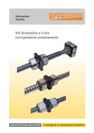
Technical Data<br />
SBC LINEAR RAIL SYSTEM FEATURES<br />
Circular-Arc raceway structure achieves the high rigidity and large permissible load.<br />
Four row circular arc groove with 2 points contact creates the same load in all directions.<br />
DF structure maintains low instrumental errors.<br />
Low frictional coefficient achieves the high energy efficiency.<br />
Easy maintenance.<br />
Improve the productivity of the machine.<br />
Various options, Easy machine design and Longer life span.<br />
Comparison the Linear Rail System with others<br />
Item Linear Rail System Plane Ball System Sliding Friction <strong>Guide</strong><br />
Assembly Self-adjusting Additional working need<br />
Precision Absorbing errors X Machining necessary<br />
Maintenance Various grease feeding Hard to grease feeding<br />
Sway X<br />
Impact Low rating load <br />
Moment High rating load Low rating load Vulnerable to eccentric load<br />
/ 4
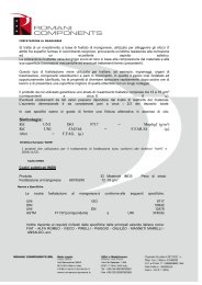
Technical Data<br />
Linear Rail System<br />
DF Structure<br />
DF structure maintains low instrumental errors.<br />
Applied model : SBI, SBG, SBS, SPG, SPS<br />
The Structure of Raceway Groove and Ball<br />
Contact<br />
Circular-Arc Groove, Four Raceway, Two-Point<br />
Contact Structure absorb the instrumental errors<br />
and create smooth movement even under high<br />
load operation.<br />
Applied Model : SBI, SBG, SBS, SPG, SPS<br />
Gothic-Arch Groove, Two Row, Four Point Contact<br />
Structure is not effective for absorbing errors but<br />
it is optimized for miniaturized machine which is<br />
necessary for smooth movement under high load<br />
condition.<br />
Applied Model: SBM, SBML, SBMW<br />
/ 5
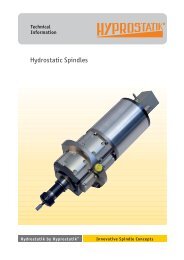
Technical Data<br />
Load Rating & Life<br />
Under normal conditions, the linear rail system can be damaged by metal fatigue as the result of<br />
repeated stress. The repeated stress causes flaking of the raceways and steel balls. The life of linear<br />
rail system is defined as the total travel distance that the linear rail system travels until flaking occurs.<br />
Nominal Life : L ( km)<br />
We define the nominal life as the total distance of travel (L=km) without flaking by 90% of a group of an<br />
identical group of linear rail systems operating under the same condition.<br />
[In case of ball]<br />
L : Nominal life<br />
P : Pay load<br />
C : Basic dynamic load rating<br />
[In case of roller]<br />
Basic Dynamic Load Rating : C ( kN)<br />
The basic dynamic load rating C is a statistical number and it is based on 90% of the bearings<br />
surviving 50Km of travel carrying the full load.<br />
Basic Static Load Rating : Co ( kN)<br />
If an excessive load or shock is applied to the linear rail system in the static or dynamic state,<br />
permanent but local deformation can occur to the steel balls and raceway. The Basic Static Load<br />
Rating is the maximum load the bearing can accept without affecting the dynamic life. This value is<br />
usually associated with a permanent deformation of the race way surface of 0.0001 time the ball<br />
diameter<br />
/ 6
Technical Data<br />
Linear Rail System<br />
Static Permissible Moment : Mo ( kN.m)<br />
These load are maximum moments or torque<br />
loads that can be applied to the bearing without<br />
damaging the bearing or affecting subsequent<br />
dynamic life.<br />
Mro : Moment in rolling direction<br />
Mpo : Moment in pitching direction<br />
Myo : Moment in yawing direction<br />
(Table, Static Safety Factor)<br />
(Radial Load)<br />
(Moment Load)<br />
Static Safety Factor : fs<br />
When calculating a load exerted on the linear rail<br />
system, both mean load and maximum load<br />
need to be considered. Reciprocating machines<br />
create moment of inertia. When selecting the<br />
right linear rail system, consider all of the loads.<br />
Co<br />
P<br />
Mo<br />
M<br />
: Basic Static Load Rating<br />
: Pay Load<br />
: Static Permissible Moment (Mpo, Mro, Myo)<br />
: Pay Load Moment<br />
Operating Load conditions fs<br />
Normally stationary<br />
Normally moving<br />
Impact load or machine deflection is<br />
small<br />
1.0 ~ 1.3<br />
Impact or twisting load is applied 2.0 ~ 3.0<br />
Normal load is exerted or machine<br />
deflection is small<br />
1.0 ~ 1.5<br />
Impact or twisting load is applied 2.5 ~ 7.0<br />
/ 7
Technical Data<br />
Frictional Resistance<br />
The static and dynamic coefficient of friction of the SBC linear rail systems are so small that they<br />
minimize the required driving force and temperature increase. Frictional force depends on load,<br />
preload, velocity and lubrication. In general, the light load with high speed is more affected by the<br />
lubricant, while the medium or heavy load are more affected by the load and are less sensitive to<br />
lubrication selection.<br />
*Coefficient of friction for linear rail system() : 0.002~0.004<br />
<br />
P:Load<br />
C:Basic dynamic load<br />
rating<br />
Pay load ratio (P/C)<br />
(Relationship between pay load and coefficient of friction)<br />
Calculate comparison by different guide system<br />
F = P<br />
F : Frictional force<br />
: Coefficient of friction<br />
P : Load<br />
(1) Linear rail system<br />
P : 5000N<br />
: 0.003<br />
F = 0.003 x 5000N = 15N<br />
(2) Sliding linear rail system<br />
P : 5000N<br />
: 0.2<br />
F = 0.2 x 5000N = 1000N<br />
/ 8
Technical Data<br />
Linear Rail System<br />
The procedure of selecting linear rail system<br />
- Machine structure<br />
- Space for guide part<br />
- Installation direction<br />
- Stroke length<br />
- Pay load<br />
- Velocity<br />
- Required lifetime<br />
- Cycle time<br />
- Working environment:<br />
(Material, lubrication and<br />
surface treatment must<br />
be considered in special<br />
working environment<br />
/ 9
Technical Data<br />
Select the system / Model<br />
1. Select System<br />
Select the appropriate guide system after considering rigidity, cost of machine and manufacturing time.<br />
2. Select Model<br />
Select the few models based on simple calculation, space and experience.<br />
3. Calculate the load and life time<br />
Judge the expected life time after calculating the load and life time and apply the model to machine<br />
design.<br />
3-1. Calculating the applied loads<br />
Loads exerted on a linear rail system vary according to direction. It is important to consider this<br />
condition before selecting the type of linear rail systems and model. Refer to the below example when<br />
calculating the loads.<br />
[Condition of calculating the applied load]<br />
Select the few models after considering space and experience and simple calculation for working<br />
conditions.<br />
m (kg)<br />
n (mm)<br />
Pn<br />
PnT<br />
: Load<br />
: Distance(mm)<br />
: Radial load<br />
: Lateral load<br />
g (m/s 2 ) : Gravitational acceleration (= 9.8 m/s 2 )<br />
V (m/s)<br />
an (m/s 2 )<br />
: Velocity<br />
: Acceleration<br />
/ 10
Technical Data<br />
Linear Rail System<br />
Calculating the applied loads and life time<br />
Condition 1<br />
Horizontal axis<br />
Condition 2<br />
Horizontal axis with overhung<br />
/ 11
Technical Data<br />
Condition 3<br />
Vertical axis<br />
Condition 4<br />
Vertical axis with wall mounted<br />
/ 12
Technical Data<br />
Linear Rail System<br />
Condition 5<br />
Horizontal axis with rail movable<br />
Condition 6<br />
Lateral axis<br />
/ 13
Technical Data<br />
Condition 7<br />
Longitudinal axis<br />
/ 14
Technical Data<br />
Linear Rail System<br />
Condition 8<br />
Horizontal axis with inertia<br />
Acceleration<br />
In uniform motion<br />
Deceleration<br />
/ 15
Technical Data<br />
3-2. Calculating the Equivalent Load<br />
Linear Rail Systems can accept normal and moment (Mro, Mpo, Myo) loads in all directions including<br />
radial, reverse-radial and lateral loads at the same time. Therefore, calculate the equivalent load<br />
accordingly.<br />
Pn<br />
PnT<br />
: Vertical load<br />
: Horizontal load<br />
PE (Equivalent load) = Pn + PnT<br />
Pn Radial load Mro Moment in rolling direction<br />
PL Reverse-radial load Mpo Moment in pitching direction<br />
PnT Laterall load Myo Moment in yawing direction<br />
/ 16
Technical Data<br />
Linear Rail System<br />
3-3. Static Safety Factors (fs)<br />
When calculating a load exerted on the linear rail system, both mean and maximum load need to be<br />
considered. Reciprocating machines create moment of inertia. When selecting the right linear rail<br />
system, consider all of loads.<br />
Radial load is<br />
large<br />
Reverse-radial<br />
load is large<br />
laterall load is<br />
large<br />
fS : Static safety factor<br />
Co(N) : Basic static load rating (radial)<br />
CoL(N) : Basic static load rating (reverse-radial)<br />
CoT(N) : Basic static load rating (lateral)<br />
Pn(N) : Calculated load (radial)<br />
PL(N) : Calculated load (reverse-radial)<br />
PnT(N) : Calculated load (lateral)<br />
fH : Hardness factor<br />
fT : Temperature factor<br />
fC : Contact factor<br />
[Value of static safety factor (fs)]<br />
Operating Load conditions Lower limit of fs<br />
Normally stationary<br />
Normally moving<br />
Impact load or machine<br />
deflection is small<br />
1.0 ~ 1.3<br />
Impact or twisting load is applied 2.0 ~ 3.0<br />
Normal load is exerted or<br />
machine deflection is small<br />
1.0 ~ 1.5<br />
Impact or twisting load is applied 2.5 ~ 7.0<br />
/ 17
Technical Data<br />
3-4. Calculating the Mean Load<br />
Loads acting on a linear rail system can vary according to various conditions. All load conditions must<br />
be taken into consideration in order to calculate the required linear rail system capacity<br />
[Equation for calculating the mean load]<br />
Pm : Mean load (N)<br />
Pn : Varying load (N)<br />
L : Total length of travel (mm)<br />
Ln : Length of travel carrying Pn (mm)<br />
1) Step loads 2) Loads that vary linearly<br />
Pm : Mean load (N)<br />
Pn : Varying load (N)<br />
L : Total length of travel (mm)<br />
Ln : Length of travel carrying Pn (mm)<br />
Pmin : Minimum load (N)<br />
Pmax : Maximum load (N)<br />
/ 18
Technical Data<br />
Linear Rail System<br />
3) Loads varying sinusoidally<br />
/ 19
Technical Data<br />
3-5. Life Calculation<br />
The equation of nominal life for linear rail system is shown as below.<br />
[Calculation of nominal life]<br />
L (km)<br />
PC(N)<br />
C (N)<br />
fH<br />
fT<br />
fC<br />
fW<br />
: Nominal life<br />
: Calculated load<br />
: Basic dynamic load rating<br />
: Hardness factor<br />
: Temperature factor<br />
: Contact factor<br />
: Load factor<br />
Hardness factor (fH)<br />
To optimize the load capacity of a linear rail<br />
system, the hardness of the rail should be<br />
HRC 58~62.<br />
The value for linear rail system is normally 1.0<br />
since the linear rail system has sufficient<br />
hardness.<br />
Temperature factor (fT)<br />
If the temperature of the linear rail system is over<br />
100°C, The hardness of the block and rail will be<br />
reduced, and as the result, the temperature<br />
factor, ft should be taken into Account.<br />
The value for linear rail system is normally 1.0<br />
when operation temperature is under 80°C.<br />
Please contact us if you need linear rail<br />
system with over 80°C working condition.<br />
/ 20
Technical Data<br />
Linear Rail System<br />
Contact factor (fC)<br />
When two or more blocks are used in close<br />
contact, it is hard to obtain a uniform load<br />
distribution because of mounting errors and<br />
tolerances. The basic dynamic load C should be<br />
multiplied by the contact factors fc shown here.<br />
Number of blocks in<br />
close contact<br />
2<br />
3<br />
4<br />
5<br />
6 or more<br />
Contact factor fc<br />
0.81<br />
0.72<br />
0.66<br />
0.61<br />
0.6<br />
Normal condtion 1.0<br />
Load factor (fW)<br />
Reciprocating machines create vibrations. The<br />
effects of vibrations are difficult to calculate<br />
precisely. Refer to the following table to<br />
compensate for these vibrations.<br />
Vibration and<br />
Impact<br />
Very slight<br />
Slight<br />
Velocity (V)<br />
Very low<br />
V0.25m/s<br />
Low<br />
0.25V1.0m/s<br />
Load<br />
factor fW<br />
1 ~ 1.2<br />
1.2 ~ 1.5<br />
Moderate<br />
Medium<br />
1.0V2.0m/s<br />
1.5 ~ 2.0<br />
Strong<br />
High<br />
V2.0m/s<br />
2.0 ~ 3.5<br />
[Life calculation]<br />
When the nominal life (L) is calculated. The life of linear rail system can be calculated by following<br />
equation, if the stroke and reciprocating cycles per minute are constant.<br />
Lh (h)<br />
L (km)<br />
s (mm)<br />
: Hours of nominal life<br />
: Nominal life<br />
: Stroke<br />
n1 (min -1 ) : Reciprocation cycles per minute<br />
/ 21
Technical Data<br />
4. Rigidity<br />
4-1. Radial-Clearance<br />
The block side to side movement by vibration is<br />
called clearance.<br />
Clearance checking<br />
After mounting the linear rail system, move the<br />
block up and down then check the change of<br />
value.<br />
4-2. Preload<br />
Preload affects the rigidity, internal-load and clearance. Also, it is very important to select appropriate<br />
preload according to applied load, impact and vibration expected in the application.<br />
Preload Conditions Example<br />
K3<br />
[Heavy<br />
preload]<br />
Where rigidity is required, vibration and<br />
impact are present.<br />
Engineered machinery for heavy equipment<br />
Machining center<br />
NC lathe<br />
Grinding machine<br />
Milling machine<br />
Vertical axis of machine tool<br />
K2<br />
[Light preload]<br />
K1<br />
[Normal<br />
preload]<br />
Where overhung loads or moment occur<br />
Single axis operation.<br />
Light load that requires precision.<br />
Where the load direction is constant, impact<br />
and vibration are light.<br />
Precision is not required<br />
Measuring equipment<br />
Electric discharge machine<br />
High speed material handling<br />
equipment<br />
NC drilling machine<br />
Industrial robot<br />
Z axis for general industrial<br />
equipment<br />
Welding machine<br />
Binding machine<br />
Automatic wrapping machine<br />
Material handling equipment<br />
/ 22
Technical Data<br />
Linear Rail System<br />
4-3. Rigidity<br />
When the load is applied to Linear Rail Systems, the balls, blocks and rails experience the elastic<br />
deformation within permissible range. The ratio of displacement is known as the rigidity.<br />
The rigidity increases as the preload increases.<br />
In case of four way equal load type, the preload is available until the load increases to some 2.8 times<br />
the preload applied.<br />
K (N/µm)<br />
(µm)<br />
P (N)<br />
: Rigidity<br />
: Displacement<br />
: Calculated load<br />
5. Accuracy<br />
Accuracy of linear rail system is generally defined by the running parallelism or the vertical and<br />
horizontal variations between the block and the rail mounting surfaces.<br />
5-1. Running parallelism<br />
It is tolerance of parallelism between reference of<br />
block and rail when the rail is mounted and block<br />
is moving in the whole length of rail.<br />
5-2. Difference in Height<br />
Difference in height between blocks on the same rail.<br />
5-3. Difference in width<br />
Difference in width between rail and blocks on the same rail<br />
5-4. Accuracy level<br />
Accuracy levels are divided into three type – N, H and P.<br />
See the dimension pages for each accuracy.<br />
/ 23
Technical Data<br />
6. Design of system<br />
Mounting method, tolerance of the mounting sufraces, and order in which the rails are mounted all<br />
affect the accuracy of machine,. Therefore we recommend considering below conditions.<br />
6-1. Identifying reference surface<br />
The unmarked edge of the block and the lined edge of the rail define the reference surfaces. Please<br />
note the methods below for locating these surfaces in your design.<br />
[Master linear rail system]<br />
[Subsidiary linear rail system]<br />
[Example of identifying reference line for pair usage]<br />
D<br />
B<br />
: Reference line of block<br />
: Reference line of rail<br />
/ 24
Technical Data<br />
Linear Rail System<br />
[Rail joint marking]<br />
For extremely long travel applications it may be necessary to join the rails via a butt joint. These joint<br />
are matched for continuous smooth motion at the factory and numbered. When installing the<br />
segments insure that the numbers at the joints match. In the case of a double rail system the first of<br />
the two numbers identifies the rail.<br />
Two rail joining method<br />
2 axis application and multiple rail joining method<br />
/ 25
Technical Data<br />
6-2. Shoulder height and fillet radius R<br />
When the bearing and rail are installed on the table and base, the fillet radius, chamfer size and<br />
shoulder height must be considered.<br />
See the each pages for shoulder height and fillet radius R.<br />
/ 26
Technical Data<br />
Linear Rail System<br />
6-3. Permissible tolerance of mounting surface<br />
Mounting errors can cause rolling resistance to motion. Due to the self adjusting feature of the SBC<br />
linear rail system, rolling resistance or bearing will not be affected as long as the permissible tolerance<br />
is observed as per the table shown in the catalogue.<br />
See the each page for permissible tolerance of mounting surface.<br />
[Permissible tolerance (P) of parallelism]<br />
[Permissible tolerance (S) of rail mounting surface height variation]<br />
/ 27
Technical Data<br />
6-4. Mounting linear rail system<br />
[Securing Method for Blocks and Rails]<br />
Normally, both the bearing block and rail are mounted to the structure with bolts. When a horizontal<br />
load is applied, shock, or vibration, it is recommended that the rail be clamped horizontally against the<br />
reference surface.<br />
(1) Cap screw mounting<br />
Small bolts are used when space is limited. The<br />
number of bolts can be adjusted as necessary.<br />
(2) Horizontal clamp mounting<br />
This method provides an easy solution to shock<br />
and vibration applications.<br />
(3) Tapered Gib<br />
This method offers the most secure means for<br />
locating the rail and block against the reference<br />
surface.<br />
(4) Dowel Pin<br />
Where the forces are lower and the costs more<br />
critical, dowel pins can be used to fix the rail.<br />
/ 28
Technical Data<br />
Linear Rail System<br />
[Rail Mounting procedure]<br />
Clean and dry the mounting surface.<br />
Coat each surface with low viscosity spindle oil, then place the rail on the surface and then lightly<br />
tighten the mounting bolts temporarily.<br />
Place the carriage plate on the blocks carefully and tighten the mounting bolts temporarily.<br />
Position the carriage plate by tightening the master block against the reference surface using the<br />
selected securing method and tighten the mounting bolts with a torque wrench.<br />
Follow the above order to mount subsidiary blocks.<br />
Checking the mounting<br />
Setting the rail against the datum plane<br />
Tightening set screws<br />
Final tightening of mounting bolts<br />
[Block Mounting procedure]<br />
Clamp the reference rail in place and tighten the<br />
mounting bolts with a torque wrench, making<br />
several passes to reach the desired torque<br />
Carefully position the table with bearings onto the<br />
rails and tighten the non-reference blocks with a<br />
torque wrench.<br />
Starting at one end ,move the table along the rail<br />
and tighten the non-reference rail slowly during<br />
several passes with a final pass using the torque<br />
wrench. Do not over tighten<br />
/ 29
Technical Data<br />
[Bolt mounting torque]<br />
Below bolt mounting torque is recommended for mounting the rail.<br />
Unit : N.cm<br />
Bolt<br />
Mounting torque<br />
Steel Cast iron Aluminum<br />
M2 58.8 39.2 29.4<br />
M2.3 78.4 53.9 39.2<br />
M2.6 118 78.4 58.8<br />
M3 196 127 98<br />
M4 412 274 206<br />
M5 882 588 441<br />
M6 1370 921 686<br />
M8 3040 2010 1470<br />
M10 6760 4510 3330<br />
M12 11800 7840 5880<br />
M14 15700 10500 7840<br />
M16 19600 13100 9800<br />
M20 38200 25500 19100<br />
M22 51900 34800 26000<br />
M24 65700 44100 32800<br />
M30 130000 87200 65200<br />
/ 30
Technical Data<br />
Linear Rail System<br />
7. Lubrication<br />
Lubrication for linear rail system is a key part of its performance.<br />
Reduce friction and wearing for each moving part.<br />
Eliminate the heat on linear rail system.<br />
Prevent corrosion on inside and outside of linear rail system.<br />
Dust-prevention.<br />
7-1. Lubrication requirements for linear rail system<br />
Form a strong oil film<br />
Have high thermal stability<br />
Low-friction<br />
High water resistance<br />
Oil must have high-viscosity and grease must<br />
have consistency again repeated agitation of<br />
grease<br />
Non-corrosive<br />
7-2. Comparison of lubrication<br />
A comparison of the application features for oil and grease used in linear rail system is shown in the<br />
table below.<br />
Item Grease Oil<br />
Rotation Low, intermediate High<br />
Seal Simple Cautious<br />
Lubrication change Complicated Simple<br />
Life Short Long<br />
Thermal radiation Bad Good<br />
Friction torque Large Less<br />
Performance Good Excellent<br />
/ 31
Technical Data<br />
(1) How to grease<br />
With grease gun : The grease is fed through the grease fitting on linear rail system.<br />
With pump : The grease is fed periodically by automation pump.<br />
(2) How to feed oil<br />
Oil-brushed on, sprayed or pumped.<br />
7-3. Lubricants interval<br />
Lubricants intervals vary according to the environment and working condition of machine. Therefore,<br />
below lubricant intervals are recommended. Do not mix oil and grease systems.<br />
Item Checking time Lubricant interval<br />
Working condition and<br />
outcome<br />
Grease<br />
3 ~ 6 months<br />
6 months ~ 1 year Normal working condition<br />
3000km<br />
3000km/6 months<br />
Oil<br />
1 week According to checking<br />
Volume and<br />
contamination of oil<br />
Everyday Any time Volume of oil<br />
/ 32
Technical Data<br />
Linear Rail System<br />
7-4. Class of oil<br />
Lubricant<br />
Class<br />
Oil Coolant oil, turbine oil ISOVG32 ~ 68<br />
7-5. Classification and selection of lubrication<br />
Lubricant for linear rail system must be selected after considering vibration, clean room, vacuum and<br />
working condition.<br />
SBC supplies two kinds of grease as standards.<br />
Item Application Brand<br />
Normal working condition<br />
Multipurpose industrial<br />
application<br />
Shell Alvania EP(LF)0<br />
[Korea Shell]<br />
Special working condition<br />
Clean room<br />
Vibration<br />
Wide temperature<br />
SNG 5050<br />
[NTG Korea]<br />
* Contact SBC for special lubes or MSDS sheets<br />
/ 33
Technical Data<br />
[Normal working condition: Multipurpose industrial application]<br />
[1] General<br />
Name :<br />
Shell Alvania EP(LF)0<br />
Company : Korea Shell<br />
Appearance : Bright brown<br />
color, semi-solid in normal<br />
temperature<br />
[2] Special feature<br />
High load resistance<br />
Anti-corrosive<br />
High liquidity<br />
High mechanical stability<br />
[3] Representative feature<br />
Consistency enhancer :<br />
Lithium<br />
Base oil : Mineral oil<br />
Working temperature :<br />
-30°C ~ 100°C<br />
Test item Representative value Test method<br />
Consistency<br />
[25°C, 60 times]<br />
0 NLGI *<br />
Dropping point 180°C ASTM D 566<br />
Copper plate corrosion<br />
[Method B,100°C, 24h]<br />
Evaporation<br />
[99°C, 22h]<br />
Stability of oxidation<br />
[99°C, 100h]<br />
Mixing stability<br />
[100,000cycles]<br />
1B ASTM D 4048<br />
0.40 % ASTM D 972<br />
0.40 kgf/cm 2 ASTM D 942<br />
393 ASTM D 217<br />
* NLGI :National Lubricating Grease Institute<br />
Consistency test<br />
method<br />
KS<br />
NLGI<br />
355 ~ 385 0<br />
/ 34
Linear Rail System<br />
Technical Data<br />
[Special working condition : Wide-temperature and low dust accumulating]<br />
[1] General<br />
Name : SNG5050<br />
Company : NTG Korea<br />
Appearance : Butter in<br />
normal temperature<br />
[2] Special feature<br />
Excellent stability of<br />
oxidation<br />
Long life grease<br />
Low dust accumulating and<br />
excellent chemical-resistance<br />
Wide temperature range<br />
[3] Representative feature<br />
Consistency : Urea<br />
Base oil : Synthetic oil<br />
Working temperature :<br />
-40°C ~ 200°C<br />
Consistency<br />
[25°C, 60 times]<br />
Test item<br />
Representative<br />
value<br />
Test method<br />
3 NLGI *<br />
Dropping point 280°C JIS K 2220 5.4<br />
Evaporation (22h) mass %<br />
99°C 0.11% JIS K 2220 5.6<br />
150°C 0.57% JIS K 2220 5.6<br />
Oil separation rate (24h) mass % 150°C 0.5% JIS K 2220 5.7<br />
Film evaporation (24h) mass %<br />
150°C 5.54% -<br />
180°C 16.44% -<br />
Stability of oxidation [99°C, 100h] mass % 0.015% JIS K 2220 5.8<br />
Mixing stability [100,000cycles] Pass ASTM D 1743<br />
Wear resistance<br />
( 1200rpm, 392N, room temperature 1h)<br />
0.57 ASTM D 2266<br />
* NLGI : National Lubricating Grease Institute<br />
Consistency test<br />
method<br />
KS<br />
NLGI<br />
220 ~ 250 3<br />
/ 35
Technical Data<br />
7-6. Grease fitting<br />
Select the appropriate grease fitting from below options in accordance with design.<br />
[Standard grease fitting]<br />
Front grease fitting (except SBM, SBMW) for linear rail system is standard grease fitting.<br />
(SBG, SBI front grease fitting)<br />
(SBM, SBMW front grease fitting)<br />
[Side grease fitting]<br />
When greasing is difficult because of limited space in front of the grease nipple, the side grease fitting<br />
can be supplied. (*Side grease fitting is not available for SBM, SBMW.)<br />
(SBG, SBI 15~25 FL side grease fitting)<br />
(SBG, SBI SL side grease fitting)<br />
(SBG 30~35 FL side grease fitting)<br />
(SBI 30~45 FL side grease fitting)<br />
(SBG 45~65 FL side grease fitting)<br />
(SBI 55~65 FL side grease fitting)<br />
/ 36
Technical Data<br />
Linear Rail System<br />
8. Safety design<br />
Dust prevention, rust prevention and re-lubrication according to working conditions of the linear rail<br />
system are necessary for required life time.<br />
8-1. Anti-rust<br />
3 types of surface treatment are available for anti-rust and appearance.<br />
[Chrome plating]<br />
It achieves high rust resistance and wear resistance with the coating film of over 750HV.<br />
[Raydent-treatment]<br />
For corrosion resistance, raydent surface treatment is available.<br />
This treatment is suitable for corrosion resistance.<br />
[Fluorocarbon raydent treatment]<br />
Fluorocarbon coating on raydent-treatment is suitable where high corrosion resistance is required<br />
(water or salty water working condition).<br />
(Raydent)<br />
[Caution for surface treatment]<br />
Be aware that the rail hole may not surface treated.<br />
Set the higher safety factor in case surface treated linear rail system is selected.<br />
Except above surface treatments, the other plating may cause performance problems.<br />
Contact SBC for other information on surface treatments.<br />
/ 37
Technical Data<br />
8-2. Dust protection<br />
The dimensions for each seal is shown on dimension page.<br />
[Seal options]<br />
Select the appropriate seal options according to working conditions.<br />
Item Symbol Application<br />
End seal No symbol (Standard) Normal condition<br />
End seal + end seal DD Dust condition<br />
End seal + scraper ZZ Welding spatter<br />
End seal + end seal + scraper KK Dust and chips<br />
* Bottom seal is not available for SBI, SBG, SBS15<br />
/ 38
Technical Data<br />
Linear Rail System<br />
[RC cap: rail hole cap]<br />
Contaminants invade into the bolt holes of the rail and pollute the inside of the bearing. You can use<br />
hole caps made from hardened rubber to fill the holes. RC caps are provided with the rails.<br />
RC cap mounting method <br />
Bolt the rail on the plate.<br />
Put the RC cap on the rail mounting hole and place the bigger steel plate on the cap then tap it with<br />
hammer.<br />
Check the RC cap to make sure it is properly seated.<br />
/ 39
Technical Data<br />
[ST dustproof tape]<br />
Stainless steel ST dustproof tape greatly improves rail face sealing and works in conjunction with<br />
guide block seals. Conventional plastic plugs do not offer the same improved sealing performance.<br />
ST dust proof tape<br />
Installation of ST tape <br />
After assembling a rail to the bed, clean the surface of the rail and remove any oil.<br />
Attach the ST tape slowly over the rail length to within 2 or 3 mm from each end of the rail.<br />
After attachment to the rail, apply pressure with dry cloth 3 or 4 times along the length of the rail to<br />
release encapsulated epoxy. Tape should be applied 4 to 6 hours prior to use to allow initial<br />
bonding.<br />
It is strongly recommended to wear safety gloves, the edge of this tape is sharp and can cut as you<br />
attach it to the rail.<br />
[Bellows]<br />
For the best protection of the linear rail system, bellows should be used.<br />
Reference : SBI type : SH-A<br />
SBG type : SH<br />
/ 40
Technical Data<br />
Linear Rail System<br />
8-3. High temperature design<br />
[HT end-plate]<br />
If working temperature is more than 80°C, SBC supply the high temperature end-plate which is made<br />
of aluminum.<br />
Recommended working temperature : -20 ~ 180°C<br />
For high temperature applications we can replace all plastic components with steel or aluminum.<br />
/ 41
Technical Data<br />
8-4. High dust-proof and self-lubricant container<br />
For protecting the linear rail system from fine foreign matter and where the grease feeding is not easy,<br />
SBC created the high dust-proof, (DF) seal and self-lubricant container (MF).<br />
Function and classification in accordance with seal type<br />
DF : Dust protection for fine foreign matter<br />
MF : Self lubricating for long maintenance intervals<br />
End plate<br />
Container<br />
End seal<br />
/ 42
Linear Rail System<br />
Technical Data<br />
[High dust-proof seal : DF seal]<br />
High-density felt built in DF container wipes the raceway tracking profile with a thin film of oil.<br />
An additional seal or scraper may be added for highly contaminated applications.<br />
*Container<br />
Contact felt<br />
Cover<br />
* Container<br />
- Its contact surfaces are tolerance match to the guiderail to ensure perfect sealing.<br />
(fully contat the rail and wipe the dust)<br />
Caution<br />
If you would like to use DF seal in watery or clean-room working condition, please contact SBC.<br />
/ 43
Technical Data<br />
[Self lubricant : MF container]<br />
MF (Self lubricanting) contains grease impregnated felt which feeds the grease on the raceway<br />
continuously. Each compact seal kit will guarantee total surface lubrication and long maintenance free<br />
bearing life.<br />
*Container<br />
Raceway contact felt<br />
Cover<br />
* Container<br />
- Its contact surfaces are tolerance match to the guiderail to ensure perfect sealing.<br />
(Wipe the raceway and grease is coating on the raceway)<br />
/ 44
Linear Rail System<br />
Technical Data<br />
8-5. MF container Lifetime test<br />
[Performance test]<br />
SBG20SL-1-K1-1500-N<br />
Condition Heavy Medium Light<br />
Load 4.9kN 2.5kN 1.0kN<br />
Velocity<br />
Theoretical<br />
Lifetime<br />
20m/min<br />
600km 1500km -<br />
[Grease feeding]<br />
The MF container may be re-charged by adding grease to hole inside of block with a syringe.<br />
Caution<br />
If MF container is required to use in special working condition like clean room, please contact SBC.<br />
/ 45
The Types of Linear Rail System<br />
SBI high-load type<br />
With all advantages of our SBG type, SBI improves load capacity, and increases speed capabilities<br />
for the rail system.<br />
SBI type<br />
-Type: SBI15~65<br />
SBM miniature<br />
Miniature linear rail system with compact size also achieve high-load.<br />
SBM (Standard miniature)<br />
-Type: SBM09~15<br />
SBML (High-load miniature)<br />
-Type : SBML09~15<br />
SBMW (Wide type miniature)<br />
-Type: SBMW09~15<br />
/ 46
The Types of Linear Rail System<br />
Linear Rail System<br />
SBG standard<br />
Standard SBC linear rail system.<br />
SBG type<br />
Type: SBG 15~65<br />
SBS type<br />
-Assembly height is lower than SBG type<br />
-Type : SBS 15~45<br />
SPG spacer<br />
Low noise type in which the plastic spacer are inserted in between balls.<br />
Low noise (Spacer type)<br />
Spacer are inserted in between balls<br />
SPG (=SBG dimensionally interchangeable)<br />
Type : SPG 20~35<br />
SPS (=SBS dimensionally interchangeable)<br />
-Type: SPS 20~35<br />
/ 47
SBI High-load Linear Rail System<br />
Circular arc groove<br />
Two point contact structure of circular arc groove. It keeps the function of self-aligning and smooth<br />
rolling performance.<br />
45° angle of contact<br />
Four rows of circular arc groove contact balls at an angle of 45 degrees provides the same capacity in<br />
all directions.<br />
DF structure<br />
Low noise and High rigidity<br />
Optimized ball recirculation structure and design provides low noise and high-rigidity.<br />
The same dimension<br />
The dimension of height, width and mounting holes are the same as SBG series, with only a slight<br />
variation in block length.<br />
/ 48
SBI High-load Linear Rail System<br />
Linear Rail System<br />
The feature of structure<br />
Linear rail<br />
Linear block<br />
Upper retainer<br />
Return tube plate<br />
End plate<br />
End seal<br />
Bottom retainer<br />
End seal New double lip structure which<br />
improves resistance to dust and particle<br />
contamination.<br />
End-plate Manufactured with a new high rigidity<br />
engineered plastic. Designed to withstand the<br />
highest of unplanned impact loads without<br />
breaking.<br />
Retainer Ball retainer plates now snap<br />
assembled to the blocks and this unique assembly<br />
method allows an amount of internal self-alignment<br />
and load sharing while maintaining rigid ball<br />
control.<br />
Linear block Highly rigid structure with a lager<br />
recirculation radius for the smooth movement<br />
and longer block length for higher load capacity.<br />
Return tube plate The end plate and reversing<br />
ramps of new ball return tubes are now molded as<br />
one complete body. This allows for smoother ball<br />
rotation through the critical transition points,<br />
significantly improving rolling performance, lower<br />
operating better lubricant retention inside the bearing.<br />
Linear rail SBI rail is designed with a low profile<br />
and wide base. This characteristic allows greater<br />
stability in operation and during manufacture.<br />
Results in greater linear precision.<br />
/ 49
SBI High-load Linear Rail System<br />
[Low noise]<br />
SBI25 / SBG25 noise level test data<br />
(Comparison of noise level)<br />
(SBI 1.3m/sec)<br />
[High load performance]<br />
SBI type is improved load capacity from the longer block length and changed radius of curvature<br />
The comparison of SBI / SBG block length<br />
L1 length SBG SBI<br />
(Unit : mm)<br />
L1<br />
15SL 38.8 45.2<br />
20SL 50.8 56.8<br />
25SL 59.5 70<br />
/ 50
SBI High-load Linear Rail System<br />
Linear Rail System<br />
The comparison of basic dynamic load rating<br />
Improved geometry and tolerances increases<br />
basic dynamic load rating<br />
(Comparison of basic dynamic load rating)<br />
Comparison of lifetime calculation<br />
L (km) : Nominal life<br />
C (kN) : Basic dynamic load rating<br />
P (kN) : Calculated load<br />
In case of P = 5 kN<br />
Basic dynamic load rating (C) of SBI20 SL : 22.2 kN<br />
Basic dynamic load rating (C) of SBG20 SL : 14.2 kN<br />
/ 51
SBI High-load Linear Rail System<br />
Accuracy<br />
(Unit : mm)<br />
Item N H P<br />
Tolerance for the height H 0.1 0.04 0.02<br />
Tolerance for the rail-to-block lateral distance W2 0.1 0.04 0.02<br />
Tolerance for the height H difference among blocks 0.03 0.015 0.007<br />
Tolerance for rail-to-block lateral distance W2 distance among blocks 0.03 0.015 0.007<br />
Running parallelism of surface C with surface A<br />
Running parallelism of surface D with surface B<br />
C<br />
D<br />
N : Normal H : High P : Precision<br />
Preload<br />
Reference<br />
K0 (None)<br />
Volume of preload<br />
Clearance within 0.01mm<br />
K1 (Normal) Max. 0.02C<br />
K2 (Light) 0.04 ~ 0.06C<br />
K3 (Heavy) 0.08 ~ 0.10C<br />
C(kN) : Basic dynamic load rating<br />
“K3” Preload is not available for SBI15 type<br />
/ 52
SBI High-load Linear Rail System<br />
Linear Rail System<br />
Shoulder height and fillet radius R<br />
(Unit : mm)<br />
Model number Fillet radius R Shoulders height H1 Shoulders height H2 <br />
15 0.6 7 2.5 3<br />
20 0.6 8 3.5 4.6<br />
25 1 10 4.5 5.5<br />
30 1 11 5 7<br />
35 1 13 6 7.5<br />
45 1.6 16 8 9<br />
55 1.6 20 10 12<br />
65 1.6 25 15 19<br />
/ 53
SBI High-load Linear Rail System<br />
Permissible tolerance (P) of parallelism<br />
Model size K1 K2 K3<br />
15 0.025 0.018 -<br />
20 0.025 0.020 0.018<br />
25 0.030 0.022 0.020<br />
30 0.040 0.030 0.027<br />
35 0.050 0.035 0.030<br />
45 0.060 0.040 0.035<br />
55 0.070 0.050 0.045<br />
65 0.080 0.060 0.055<br />
(Unit : mm)<br />
/ 54
SBI High-load Linear Rail System<br />
Linear Rail System<br />
Permissible tolerance (S) of two level offset<br />
Model size K1 K2 K3<br />
15 0.13 0.085 -<br />
20 0.13 0.085 0.05<br />
25 0.13 0.085 0.07<br />
30 0.17 0.11 0.09<br />
35 0.21 0.15 0.12<br />
45 0.25 0.17 0.14<br />
55 0.30 0.21 0.17<br />
65 0.35 0.25 0.20<br />
(Unit : mm)<br />
/ 55
SBI High-load Linear Rail System<br />
SH Bellows<br />
Model Applicabl<br />
a (*Dimensions according to block types)<br />
W H H1 P1 P2 P3<br />
number e type<br />
FV SV CL FL SL HL<br />
b1 b2<br />
SH15 A<br />
25 25 15<br />
4 4 - 4 0 4<br />
SBI15 50<br />
15.5 1<br />
SH15 DA 20 20 10 -1 -1 - -1 -5 -1<br />
26 -<br />
SH20 A<br />
29 31 17<br />
5.5 5.5 5.5 3.5 3.5 - 34<br />
SBI20 60<br />
18 1<br />
SH20 DA 24 26 12 - - - -1.5 -1.5 - (32)<br />
-<br />
SH25 A<br />
35 35 20<br />
7 7 7 4 0 4<br />
SBI25 70<br />
21 1<br />
SH25 DA 30 30 15 - - - -1 -5 -1<br />
36 -<br />
SH30 A<br />
36 36 20<br />
- - - 1 -2 1<br />
SBI30 80<br />
23 1<br />
SH30 DA 33 33 17 - - - -2 -5 -2<br />
49 -<br />
SH35 DA SBI35 85 39 39 20 22.5 1 - - - -2 -9 -2 56 -<br />
SH45 DA SBI45 100 48 48 25 25 1 - - - -3 -13 -3 72 -<br />
SH55 DA SBI55 110 56 56 30 25 1 - - - -2 -12 -2 74 53.4<br />
SH65 DA SBI65 130 69 69 35 30 1 - - - -2 -2 - 90 64<br />
* The column of b1 dimension is only applying for SBI20CLS type.<br />
* The dimension in column “a, b3 and b4” are common for FL=FLL, SL=SLL and HL=HLL, HLS.<br />
* If SH bellows are applying, rail end mounting holes are necessary.<br />
* When you select SH bellows, please select the side grease fitting for lubrication.<br />
* Please contact SBC for more information.<br />
/ 56
SBI High-load Linear Rail System<br />
Linear Rail System<br />
[Calculation of bellows length]<br />
Lmax<br />
Lmin<br />
: Extended length (mm)<br />
: Collapsed length (mm)<br />
Lmin<br />
SBI 15, 20 Stroke 5<br />
SBI 25~45 Stroke 6<br />
SBI 55~65 Stroke 7<br />
Lmax<br />
Lmin + Stroke<br />
b3<br />
b4<br />
M x Bolt length<br />
t1 t2 t3 t4<br />
FL SL HL FV SV CL FL SL HL M1(Block) M2(Rail)<br />
(Unit : mm)<br />
A<br />
Extended<br />
ratio<br />
- - - 13.3 13.3 - 13.3 17.3 13.3 10 - - - M3X16 M4X8 6<br />
- - - 14 14 14 16 16 - 6 8 - - M3X18 M3X6 6<br />
- - - 16.3 16.3 16.3 19.3 23.3 19.3 10 7 - - M3X18 M3X6 7<br />
- - - - - - 22.8 25.8 22.8 11 8 - - M4X22 M4X8 7<br />
- - - - - - 26.5 33.5 26.5 - - 14 21 M4X22 M4X8 7<br />
- - - - - - 33.5 43.5 33.5 - - 20 25 M4X25 M5X10 7<br />
7 17 7 - - - 38.5 48.5 38.5 - - 26 29 M5X30 M5X10 8<br />
7 7 - - - - 45 45 - - - 34 42 M5X35 M5X10 8<br />
Ordering example : SH25A – 70 / 420<br />
<br />
Model number<br />
Collapsed length (mm)<br />
Extended length (mm)<br />
H’ dimesion of SH-DA type is lower than SH-A type<br />
/ 57
SBI High-load Linear Rail System<br />
RC Cap<br />
(Unit : mm)<br />
Model D±0.1 H±0.1<br />
RC 15 7.6 1.3<br />
RC 20 9.6 3.5<br />
RC 25 11.1 2.8<br />
*RC 30 14.2 3.7<br />
RC 45 20.2 4.7<br />
RC 55 23.2 6<br />
RC 65 26.2 6<br />
RC 30 is used for SBI 30, 35 rail.<br />
SBI, SBG type use same RC cap.<br />
ST Tape<br />
(Unit : mm)<br />
Model W t<br />
ST 15A 11 0.1<br />
ST 20A 15 0.1<br />
ST 25A 17 0.1<br />
ST 30A 21 0.1<br />
ST 35A 27 0.1<br />
ST 45A 37 0.1<br />
ST 55A 43 0.1<br />
ST 65A 51 0.1<br />
Ordering example : ST15A - 1000L<br />
<br />
Model number<br />
Length<br />
/ 58
Linear Rail System<br />
SBI High-load Linear Rail System<br />
Seal and MF container<br />
[Method and overall length with each seal]<br />
E : End seal S : Scraper F : DF (High dust protection seal). MF (Self lubricant)<br />
(Unit : mm)<br />
Additional seal Standard DD ZZ KK D(M)F D(M)FDD D(M)FZZ D(M)FKK<br />
Indication of seal E E+E E+S E+E+S F+E F+E+E F+E+S F+E+E+S<br />
15V 39.9 44.5 45.3 49.9 53.9 58.5 59.3 63.9<br />
<br />
15 63.8 68.4 69.2 73.8 77.8 82.4 83.2 87.8<br />
15L 79.4 84 84.8 89.4 93.4 98 98.8 103.4<br />
20V 49.1 54.1 54.5 59.5 63.1 68.1 68.5 73.5<br />
Overall<br />
length<br />
with seal<br />
<br />
20 78.8 83.8 84.2 89.2 92.8 97.8 98.2 103.2<br />
20L 96.4 101.4 101.8 106.8 110.4 115.4 115.8 120.8<br />
25V 52.6 57.6 58 63 66.6 71.6 72 77<br />
25 92 97 97.4 102.4 106 111 111.4 116.4<br />
25L 108 113 113.4 118.4 122 127 127.4 132.4<br />
30 107.6 113.6 114 120 123.6 129.6 130 136<br />
30L 131.6 137.6 138 144 147.6 153.6 154 160<br />
35 124.6 130.6 131 137 140.6 146.6 147 153<br />
35L 152.6 158.6 159 165 168.6 174.6 175 181<br />
45 142 148 148.4 154.4 158 164 164.4 170.4<br />
45L 174 180 180.4 186.4 190 196 196.4 202.4<br />
55 172.4 179.4 179.2 186.2 190.4 197.4 197.2 204.2<br />
55L 211.8 218.8 218.6 225.6 229.8 236.8 236.6 243.6<br />
65 219.8 226.8 226.6 233.6 237.8 244.8 244.6 251.6<br />
65L 272.2 279.2 279 286 290.2 297.2 297 304<br />
Bottom seal of SBI type is integrated with bottom retainer. (Except SBI15)<br />
If block is assembled with MF container, the grease fitting is not supplied. If you would like to feed<br />
the grease to the block, please order side grease fitting type.<br />
/ 59
SBI High-load Linear Rail System<br />
[Dimension of MF container]<br />
(Unit : mm)<br />
Reference Model Applied model Block type W t H D<br />
15A SBI15<br />
FL/FLL/HL/HLL/HLS<br />
SL/SLL/FV/SV<br />
33.4 7 20.2 4<br />
20A<br />
FL/FLL<br />
24.6<br />
SBI20<br />
SL/SLL 43.4 7<br />
6.5<br />
20B CL/CLL/FV/SV 22.6<br />
25A<br />
FL/FLL/HL/HLL<br />
29.7<br />
SBI25<br />
SL/SLL 47 7<br />
6.5<br />
25B CL/CLL/FV/SV 26.7<br />
DF / MF 30A SBI30<br />
FL/FLL/HL/HLL<br />
SL/SLL<br />
59 8 34.2 6.5<br />
35A SBI35<br />
FL/FLL/HL/HLL<br />
SL/SLL<br />
69 8 39.7 6.5<br />
45A SBI45<br />
FL/FLL/HL/HLL<br />
SL/SLL<br />
85 8 49.7 10.5<br />
55A SBI55<br />
FL/FLL/HL/HLL<br />
SL/SLL<br />
98 9 56 10.5<br />
65A SBI65<br />
FL/FLL<br />
SL/SLL<br />
123 9 69 10.5<br />
[Seal resistance]<br />
For the maximum value of seal resistance of SBI<br />
standard type per block, in which grease is not<br />
applied.<br />
Scraper has no resistance because it is not<br />
contacting rail.<br />
(Unit : N)<br />
Model End seal DF MF<br />
SBI 15 2.0 4.7 3.5<br />
SBI 20 2.5 4.9 3.0<br />
SBI 25 3.0 5.5 3.5<br />
SBI 30 3.9 5.6 3.5<br />
SBI 35 2.5 5.7 3.7<br />
SBI 45 3.4 5.9 4.1<br />
SBI 55 3.5 6.2 4.2<br />
SBI 65 3.6 6.4 4.4<br />
/ 60
Linear Rail System<br />
SBI High-load Linear Rail System<br />
HT high temperature end plate<br />
(Unit : mm)<br />
Reference<br />
HT<br />
Overall length<br />
Length Applied model L0 Applied model L0 Applied model L0 Applied model L0<br />
HT 15A 6.5 SBI 15V 38.3 SBI 15S 53.2 SBI 15 62.2 SBI 15L 77.8<br />
HT 20A 8 SBI 20V 47.1 SBI 20S 63.2 SBI 20 76.8 SBI 20L 94.4<br />
HT 25A 8 SBI 25V 50.6 - - SBI 25 90 SBI 25L 106<br />
HT 30A 10 - - - - SBI 30 105.6 SBI 30L 129.6<br />
HT 35A 11 - - - - SBI 35 122.6 SBI 35L 150.6<br />
HT 45A 13 - - - - SBI 45 140 SBI 45L 172<br />
HT 55A 16 - - - - SBI 55 168.5 SBI 55L 207.9<br />
HT 65A 20 - - - - SBI 65 215.9 SBI 65L 268.3<br />
Ordering example : SBI25FL - HT - 2 - K1 - 800 - N<br />
<br />
Model<br />
High temperature<br />
end plate<br />
Block quantity<br />
Preload<br />
Rail length<br />
Accuracy<br />
All plastic components are replace with steel or aluminum in the High Temperature Blocks.<br />
Side grease fitting is not available for high temperature end plates<br />
Grease and nipple specification<br />
[Grease]<br />
SBI uses two types of grease according to working conditions.<br />
For details, please see the technical data for grease.<br />
/ 61
SBI High-load Linear Rail System<br />
(1) Standard grease fitting (Front grease fitting) (Unit : mm)<br />
Specification<br />
M4x0.7P<br />
Applied model Grease fitting model Symbol L L1<br />
1N None 7 5.5<br />
SBI 15<br />
1D DD, ZZ 5 9<br />
1Z KK 5 11<br />
1F DF,DFDD, DFZZ, DFKK 5 13<br />
(Unit : mm)<br />
Specification<br />
M6x0.75P, Asia type<br />
Applied model Grease fitting model Symbol L L1<br />
IA2N None 13.5 7<br />
SBI 20~35<br />
IA2D DD, ZZ 13.5 10<br />
IA2Z KK, DF 13.5 13<br />
IA2F DFDD, DFZZ, DFKK 13.5 18<br />
(Unit : mm)<br />
Specification<br />
M6x1.0P, Europe type<br />
Applied model Grease fitting model Symbol L L1<br />
IE2N None 13.5 7<br />
SBI 20~35<br />
IE2D DD, ZZ 13.5 10<br />
IE2Z KK, DF 13.5 13<br />
IE2F DFDD, DFZZ, DFKK 13.5 18<br />
(Unit : mm)<br />
Specification PT 1/8<br />
Applied model Grease fitting model Symbol L L1<br />
4N None 17 12<br />
SBI 45~65 4D DD, KK, ZZ 17 16<br />
4F DF, DFDD, DFZZ, DFKK 17 23<br />
/ 62
Linear Rail System<br />
SBI High-load Linear Rail System<br />
(2) Side grease fitting<br />
Specification<br />
M4x0.7P<br />
Specification<br />
M4x0.7P<br />
Specification M6x0.75P<br />
Specification<br />
PT1/8<br />
Applied model SBI 15<br />
Applied model SBI 20, 25<br />
Applied model SBI 30, 35, 45<br />
Applied model SBI 55, 65<br />
Grease fitting model<br />
S1N<br />
Grease fitting model<br />
S2N<br />
Grease fitting model<br />
S3N<br />
Grease fitting model<br />
S4N<br />
(3) FS nipple connector for side grease fitting (FL. FLL flange type only) Please see the page /36 for assembling the nipple connector.<br />
8<br />
Specification M4x0.7P<br />
Applied model SBI 15<br />
Grease fitting model S1C<br />
(4) Copper pipe<br />
Specification M4x0.7P<br />
Applied model SBI 20, 25<br />
Grease fitting model S2C<br />
Specification<br />
M6x0.75P<br />
Applied model SBI 30, 35, 45<br />
Grease fitting model<br />
S4C<br />
* For size 30~45, two pieces of FS<br />
nipple connector are applied.<br />
5<br />
(25)<br />
12<br />
Input size PT1/8<br />
Output size M6x0.75P<br />
Applied model SBI 20, 25, 30, 35<br />
Grease fitting model SB01<br />
Input size PT1/8<br />
Output size PT1/8<br />
Applied model SBI 45, 55, 65<br />
Grease fitting model SB21<br />
/ 63
SBI High-load Linear Rail System<br />
Ordering example<br />
SBI20 FL – N – MF – ZZ – K1<br />
[1] [2] [3] [4] [5] [6]<br />
[1] Model<br />
[2] Block type : FL, FLL, FV, SL. SLL, SV, HL, HLS, HLL, CL, CLS, CLL<br />
[3] Position of grease fitting : None (front), N (side)<br />
[4] Container : No symbol (standard), DF (high dust protection), MF (self lubricant)<br />
[5] Seal : No symbol (standard), DD, ZZ, KK<br />
[6] Preload : K0, K1, K2 ,K3<br />
“K3” Preload is not available for SBI 15 type<br />
[Ordering example for rail]<br />
SBI20 – 1000L – B<br />
[1] [2] [3]<br />
[1] Model<br />
[2] Rail length<br />
[3] Bottom mounting : No symbol (standard), B (bottom mounting rail)<br />
If only rail is ordered, N grade is available.<br />
/ 64
SBI High-load Linear Rail System<br />
Linear Rail System<br />
[Ordering for assembled rail and block]<br />
SBI20 FL – N – MF – ZZ – 2 – K1 – 800 – N – R – B – II<br />
[1] [2] [3] [4] [5] [6] [7] [8] [9] [10] [11] [12]<br />
[1] Model<br />
[2] Block type : FL, FLL, FV, SL. SLL, SV, HL, HLS, HLL, CL, CLS, CLL<br />
[3] Position of grease fitting : None (front), N (side)<br />
[4] Container : No symbol (standard), DF (high dust protection), MF (self lubricant)<br />
[5] Seal : No symbol (standard), DD, ZZ, KK<br />
[6] Block quantity on rail<br />
[7] Preload : K0, K1, K2 ,K3<br />
[8] Rail length<br />
[9] Accuracy : N, H, P<br />
[10] Surface treatment<br />
[11] (B) Bottom mounting rail : No symbol (standard)<br />
[12] Rail : number of rails per axis, 1=I, 2=II... 4=IV etc.<br />
We recommend block and rail assembled to be ordered where high-precision and highrigidity<br />
are required.<br />
For surface treatment, please mark according to each surface treatment symbol.<br />
If special G dimension is required, please mark when you place an order.<br />
Please contact SBC for high temperature order.<br />
“K3” Preload is not available for SBI 15 type<br />
/ 65
SBI High-load Linear Rail System<br />
Standard and Max. Length of SBI rail<br />
(Unit : mm)<br />
Model number SBI15 SBI20 SBI25 SBI30 SBI35 SBI45 SBI55 SBI65<br />
160 220 220 280 280 570 780 1270<br />
220 280 280 440 440 885 900 1570<br />
280 240 340 600 600 1095 1020 2020<br />
340 460 460 760 760 1200 1140 2470<br />
460 640 640 1000 1000 1410 1260 2620<br />
640 820 820 1240 1240 1620 1380 2920<br />
820 1000 1000 1480 1480 1830 1500 3070<br />
1000 1240 1240 1640 1640 2040 1620 -<br />
1240 1480 1480 1800 1800 2250 1740 -<br />
1480 1600 1600 2040 2040 2460 1860 -<br />
1600 1840 1840 2200 2200 2985 1980 -<br />
1960 2080 2080 2520 2520 3510 2220 -<br />
2200 2200 2200 2840 2840 - 2580 -<br />
2500 2500 2500 3000 3000 - 2940 -<br />
2860 2960 2980 3480 3480 - 3540 -<br />
- 3520 3520 - - - - -<br />
- 4000 4000 - - - - -<br />
F 60 60 60 80 80 105 120 150<br />
Standard<br />
length<br />
G 20 20 20 20 20 22.5 30 35<br />
L0(Max length) 3,000 4,000 4,000 4,000 4,000 4,000 4,000 4,000<br />
* If the maximum length exceeds this size, butt joints can be supplied.<br />
* For more information about butt jointing, please refer to the page of safety design.<br />
* If the G is not standard, please indicate it in the order sheet.<br />
/ 66
Linear Rail System<br />
SBI High-load Linear Rail System<br />
Bottom mounting rail (SBI-B type)<br />
Model<br />
number<br />
W1 H1 S h2 G F<br />
* If the maximum length exceeds this size, please contact SBC.<br />
L0<br />
(Max length)<br />
(Unit : mm)<br />
Weight<br />
(kg/m)<br />
SBI 15-B 15 13 M5X0.8 8 20 60 3,000 1.39<br />
SBI 20-B 20 16.5 M6 9 20 60 4,000 2.37<br />
SBI 25-B 23 20 M6 9 20 60 4,000 3.26<br />
SBI 30-B 28 23 M8 12 20 80 4,000 4.63<br />
SBI 35-B 34 26 M8 12 20 80 4,000 6.45<br />
SBI 45-B 45 32 M12 18 22.5 105 4,000 10.49<br />
/ 67
SBI High-load Linear Rail System<br />
SBI-FL/FLL<br />
Mounting dimension<br />
Block dimensions<br />
Model<br />
H W L E<br />
C (Basic dynamic load rating), Co (Basic static load rating)<br />
*S: Bolt size for bottom mounting type of block.<br />
Mounting tap hole<br />
Grease fitting<br />
L1 T±1 K<br />
B J M *S T1 N1 T2 N2 Q1 *Q2<br />
SBI15 FL 24 47 63.8 3 38 30 M5 M4 45.2 9 21 4.5 5.5 3.8 3.8 M4x0.7 3.5<br />
SBI15 FLL 24 47 79.4 3 38 30 M5 M4 60.8 9 21 4.5 5.5 3.8 3.8 M4x0.7 3.5<br />
SBI20 FL 30 63 78.8 4.6 53 40 M6 M5 56.8 12 25.4 6 12 5.8 5 M6x0.75 3.5<br />
SBI20 FLL 30 63 96.4 4.6 53 40 M6 M5 74.4 12 25.4 6 12 5.8 5 M6x0.75 3.5<br />
SBI25 FL 36 70 92 5.5 57 45 M8 M6 70 14 30.5 6 12 5 5 M6x0.75 3.5<br />
SBI25 FLL 36 70 108 5.5 57 45 M8 M6 86 14 30.5 6 12 5 5 M6x0.75 3.5<br />
SBI30 FL 42 90 107.6 7 72 52 M10 M8 79.6 15.5 35 8.5 12 7.8 5 M6x0.75 5.7<br />
SBI30 FLL 42 90 131.6 7 72 52 M10 M8 103.6 15.5 35 8.5 12 7.8 5 M6x0.75 5.7<br />
SBI35 FL 48 100 124.6 7.5 82 62 M10 M8 94.6 15 40.5 8 12 8 6 M6x0.75 5.7<br />
SBI35 FLL 48 100 152.6 7.5 82 62 M10 M8 122.6 15 40.5 8 12 8 6 M6x0.75 5.7<br />
SBI45 FL 60 120 142 9 100 80 M12 M10 108 18 51 10.5 13.5 9.3 6.5 PT1/8 5.7<br />
SBI45 FLL 60 120 174 9 100 80 M12 M10 140 18 51 10.5 13.5 9.3 6.5 PT1/8 5.7<br />
SBI55 FL 70 140 172.4 12 116 95 M14 M12 131 22 58 12 13 12 8 PT1/8 8.7<br />
SBI55 FLL 70 140 211.8 12 116 95 M14 M12 170.4 22 58 12 13 12 8 PT1/8 8.7<br />
SBI65 FL 90 170 219.8 19 142 110 M16 M14 170.4 26 71 14 13 14 10 PT1/8 8.7<br />
SBI65 FLL 90 170 272.2 19 142 110 M16 M14 222.8 26 71 14 13 14 10 PT1/8 8.7<br />
/ 68
SBI High-load Linear Rail System<br />
Linear Rail System<br />
W1 W2 H1 F<br />
Rail dimension<br />
Basic load<br />
rating<br />
[kN]<br />
Permissible static<br />
moment<br />
[kNm]<br />
Bolt hole<br />
Max<br />
length<br />
G<br />
of rail<br />
d D h<br />
L0<br />
C Co Mro Mpo Myo<br />
Block<br />
[kg]<br />
(Unit : mm)<br />
Mass<br />
*Q2: The hole of side grease nipple is not made to prevent a foreign substance from going into inside.<br />
When you order the side grease nipple, we build it by ourselves.<br />
Rail<br />
[kg/m]<br />
15 16 13 60 4.5 7.5 5.5 20 3000 14.1 24.1 0.16 0.17 0.17 0.19 1.3<br />
15 16 13 60 4.5 7.5 5.5 20 3000 17.1 31.7 0.21 0.29 0.29 0.26 1.3<br />
20 21.5 16.5 60 6 9.5 8.5 20 4000 22.2 38.2 0.36 0.33 0.33 0.41 2.2<br />
20 21.5 16.5 60 6 9.5 8.5 20 4000 27.9 50 0.47 0.56 0.56 0.54 2.2<br />
23 23.5 20 60 7 11 9 20 4000 31.5 52.1 0.56 0.56 0.56 0.69 3<br />
23 23.5 20 60 7 11 9 20 4000 36.7 64.4 0.69 0.84 0.84 0.85 3<br />
28 31 23 80 9 14 12 20 4000 42.8 65.4 0.85 0.77 0.77 1.04 4.25<br />
28 31 23 80 9 14 12 20 4000 51.3 84.7 1.10 1.30 1.30 1.37 4.25<br />
34 33 26 80 9 14 12 20 4000 59.5 89.1 1.42 1.28 1.28 1.56 6.02<br />
34 33 26 80 9 14 12 20 4000 71.3 115.3 1.83 2.12 2.12 2.04 6.02<br />
45 37.5 32 105 14 20 17 22.5 4000 79.2 116.3 2.48 1.90 1.90 2.80 9.77<br />
45 37.5 32 105 14 20 17 22.5 4000 94.8 150.5 3.21 3.14 3.14 3.69 9.77<br />
53 43.5 38 120 16 23 20 30 4000 127.3 181.8 4.81 2.97 2.97 4.42 13.72<br />
53 43.5 38 120 16 23 20 30 4000 147.9 224.5 5.95 4.78 4.78 5.82 13.72<br />
63 53.5 53 150 18 26 22 35 4000 188.3 261.7 8.24 5.57 5.57 9.1 23.17<br />
63 53.5 53 150 18 26 22 35 4000 232.5 354.1 11.15 9.86 9.86 11.98 23.17<br />
/ 69
SBI High-load Linear Rail System<br />
SBI-SL/SLL<br />
Mounting dimension<br />
Block dimensions<br />
Model<br />
H W L E<br />
C (Basic dynamic load rating), Co (Basic static load rating)<br />
Mounting tap hole<br />
Grease fitting<br />
L1 T±1 K<br />
B J M DP T1 N1 T2 N2 Q1 *Q2<br />
SBI15 SL 28 34 63.8 3 26 26 M4 5 45.2 10 25 8.5 5.5 7.8 3.8 M4x0.7 3.5<br />
SBI15 SLL 28 34 79.4 3 26 34 M4 5 60.8 10 25 8.5 5.5 7.8 3.8 M4x0.7 3.5<br />
SBI20 SL 30 44 78.8 4.6 32 36 M5 5 56.8 10 25.4 6 12 5.8 5 M6x0.75 3.5<br />
SBI20 SLL 30 44 96.4 4.6 32 50 M5 5 74.4 10 25.4 6 12 5.8 5 M6x0.75 3.5<br />
SBI25 SL 40 48 92 5.5 35 35 M6 8 70 16 34.5 10 12 9 5 M6x0.75 3.5<br />
SBI25 SLL 40 48 108 5.5 35 50 M6 8 86 16 34.5 10 12 9 5 M6x0.75 3.5<br />
SBI30 SL 45 60 107.6 7 40 40 M8 10 79.6 12 38 11.5 12 10.8 5 M6x0.75 5.7<br />
SBI30 SLL 45 60 131.6 7 40 60 M8 10 103.6 12 38 11.5 12 10.8 5 M6x0.75 5.7<br />
SBI35 SL 55 70 124.6 7.5 50 50 M8 10 94.6 15 47.5 15 12 15 6 M6x0.75 5.7<br />
SBI35 SLL 55 70 152.6 7.5 50 72 M8 10 122.6 15 47.5 15 12 15 6 M6x0.75 5.7<br />
SBI45 SL 70 86 142 9 60 60 M10 13 108 17 61 20.5 13.5 19.3 6.5 PT1/8 5.7<br />
SBI45 SLL 70 86 174 9 60 80 M10 13 140 17 61 20.5 13.5 19.3 6.5 PT1/8 5.7<br />
SBI55 SL 80 100 172.4 12 75 75 M12 18 131 21 68 22 13 22 8 PT1/8 8.7<br />
SBI55 SLL 80 100 211.8 12 75 95 M12 18 170.4 21 68 22 13 22 8 PT1/8 8.7<br />
SBI65 SL 90 126 219.8 19 76 70 M16 16 170.4 26 71 14 13 14 10 PT1/8 8.7<br />
SBI65 SLL 90 126 272.2 19 76 120 M16 16 222.8 26 71 14 13 14 10 PT1/8 8.7<br />
*Q2: The hole of side grease nipple is not made to prevent a foreign substance from going into inside.<br />
When you order the side grease nipple, we build it by ourselves.<br />
/ 70
SBI High-load Linear Rail System<br />
Linear Rail System<br />
W1 W2 H1 F<br />
Rail dimension<br />
Basic load<br />
rating<br />
[kN]<br />
Permissible static<br />
moment<br />
[kNm]<br />
Bolt hole<br />
Max<br />
langth<br />
G<br />
of rail<br />
d D h<br />
L0<br />
C Co Mro Mpo Myo<br />
Block<br />
[kg]<br />
(Unit : mm)<br />
Mass<br />
Rail<br />
[kg/m]<br />
15 9.5 13 60 4.5 7.5 5.5 20 3000 14.1 24.1 0.16 0.17 0.17 0.19 1.3<br />
15 9.5 13 60 4.5 7.5 5.5 20 3000 17.1 31.7 0.21 0.29 0.29 0.26 1.3<br />
20 12 16.5 60 6 9.5 8.5 20 4000 22.2 38.2 0.36 0.33 0.33 0.41 2.2<br />
20 12 16.5 60 6 9.5 8.5 20 4000 27.9 50 0.47 0.56 0.56 0.54 2.2<br />
23 12.5 20 60 7 11 9 20 4000 31.5 52.1 0.56 0.56 0.56 0.69 3<br />
23 12.5 20 60 7 11 9 20 4000 36.7 64.4 0.69 0.84 0.84 0.85 3<br />
28 16 23 80 9 14 12 20 4000 42.8 65.4 0.85 0.77 0.77 1.04 4.25<br />
28 16 23 80 9 14 12 20 4000 51.3 84.7 1.10 1.30 1.30 1.37 4.25<br />
34 18 26 80 9 14 12 20 4000 59.5 89.1 1.42 1.28 1.28 1.56 6.02<br />
34 18 26 80 9 14 12 20 4000 71.3 115.3 1.83 2.12 2.12 2.04 6.02<br />
45 20.5 32 105 14 20 17 22.5 4000 79.2 116.3 2.48 1.90 1.90 2.80 9.77<br />
45 20.5 32 105 14 20 17 22.5 4000 94.8 150.5 3.21 3.14 3.14 3.69 9.77<br />
53 23.5 38 120 16 23 20 30 4000 127.3 181.8 4.81 2.97 2.97 4.42 13.72<br />
53 23.5 38 120 16 23 20 30 4000 147.9 224.5 5.95 4.78 4.78 5.82 13.72<br />
63 31.5 53 150 18 26 22 35 4000 188.3 261.7 8.24 5.57 5.57 9.1 23.17<br />
63 31.5 53 150 18 26 22 35 4000 232.5 354.1 11.15 9.86 9.86 11.98 23.17<br />
/ 71
SBI High-load Linear Rail System<br />
SBI-HL/HLS/HLL<br />
Model<br />
Mounting dimension<br />
H W L E<br />
Block dimensions<br />
Mounting tap hole<br />
Grease fitting<br />
L1 T±1 K<br />
B J M DP T1 N1 T2 N2 Q1 *Q2<br />
SBI15 HL 24 34 63.8 3 26 26 M4 4 45.2 6 21 4.5 5.5 3.8 3.8 M4x0.7 3.5<br />
SBI15 HLS 24 34 56.8 3 26 26 M4 4 38.2 6 21 4.5 5.5 3.8 3.8 M4x0.7 3.5<br />
SBI15 HLL 24 34 79.4 3 26 34 M4 4 60.8 6 21 4.5 5.5 3.8 3.8 M4x0.7 3.5<br />
SBI25 HL 36 48 92 5.5 35 35 M6 6 70 12 30.5 6 12 5 5.5 M6x0.75 3.5<br />
SBI25 HLL 36 48 108 5.5 35 50 M6 6 86 12 30.5 6 12 5 5.5 M6x0.75 3.5<br />
SBI30 HL 42 60 107.6 7 40 40 M8 8 79.6 12 35 8.5 12 7.8 5 M6x0.75 5.7<br />
SBI30 HLL 42 60 131.6 7 40 60 M8 8 103.6 12 35 8.5 12 7.8 5 M6x0.75 5.7<br />
SBI35 HL 48 70 124.6 7.5 50 50 M8 8 94.6 15 40.5 8 12 8 6 M6x0.75 5.7<br />
SBI35 HLL 48 70 152.6 7.5 50 72 M8 8 122.6 15 40.5 8 12 8 6 M6x0.75 5.7<br />
SBI45 HL 60 86 142 9 60 60 M10 10 108 17 51 10.5 13.5 9.3 6.5 PT1/8 5.7<br />
SBI45 HLL 60 86 174 9 60 80 M10 10 140 17 51 10.5 13.5 9.3 6.5 PT1/8 5.7<br />
SBI55 HL 70 100 172.4 12 75 75 M12 12 131 21 58 12 13 12 8 PT1/8 8.7<br />
SBI55 HLL 70 100 211.8 12 75 95 M12 12 170.4 21 58 12 13 12 8 PT1/8 8.7<br />
C (Basic dynamic load rating), Co (Basic static load rating)<br />
*Q2: The hole of side grease nipple is not made to prevent a foreign substance from going into inside.<br />
When you order the side grease nipple, we build it by ourselves.<br />
/ 72
SBI High-load Linear Rail System<br />
Linear Rail System<br />
W1 W2 H1 F<br />
Rail dimension<br />
Basic load<br />
rating<br />
[kN]<br />
Permissible static<br />
moment<br />
[kNm]<br />
Bolt hole<br />
Max<br />
langth<br />
G<br />
of rail<br />
d D h<br />
L0<br />
C Co Mro Mpo Myo<br />
Block<br />
[kg]<br />
(Unit : mm)<br />
Mass<br />
15 9.5 13 60 4.5 7.5 5.5 20 3000 14.1 24.1 0.16 0.17 0.17 0.19 1.3<br />
15 9.5 13 60 4.5 7.5 5.5 20 3000 12.3 18.3 0.13 0.08 0.08 0.15 1.3<br />
15 9.5 13 60 4.5 7.5 5.5 20 3000 17.1 31.7 0.21 0.29 0.29 0.26 1.3<br />
23 12.5 20 60 7 11 9 20 4000 31.5 52.1 0.56 0.56 0.56 0.69 3<br />
23 12.5 20 60 7 11 9 20 4000 36.7 64.4 0.69 0.84 0.84 0.85 3<br />
28 16 23 80 9 14 12 20 4000 42.8 65.4 0.85 0.77 0.77 1.04 4.25<br />
28 16 23 80 9 14 12 20 4000 51.3 84.7 1.10 1.30 1.30 1.37 4.25<br />
34 18 26 80 9 14 12 20 4000 59.5 89.1 1.42 1.28 1.28 1.56 6.02<br />
34 18 26 80 9 14 12 20 4000 71.3 115.3 1.83 2.12 2.12 2.04 6.02<br />
45 20.5 32 105 14 20 17 22.5 4000 79.2 116.3 2.48 1.90 1.90 2.80 9.77<br />
45 20.5 32 105 14 20 17 22.5 4000 94.8 150.5 3.21 3.14 3.14 3.69 9.77<br />
Rail<br />
[kg/m]<br />
53 23.5 38 120 16 23 20 30 4000 127.3 181.8 4.81 2.97 2.97 4.42 13.72<br />
53 23.5 38 120 16 23 20 30 4000 147.9 224.5 5.95 4.78 4.78 5.82 13.72<br />
/ 73
SBI High-load Linear Rail System<br />
SBI-CL/CLS/CLL<br />
Model<br />
Mounting dimension<br />
H W L E<br />
Block dimensions<br />
Mounting tap hole<br />
Grease fitting<br />
L1 T K<br />
B J M DP T1 N1 T2 N2 Q1 *Q2<br />
SBI20 CL 28 44 78.8 4.6 32 32 M5 5 56.8 7.8 23.4 4.8 12 4 5 M6x0.75 3.5<br />
SBI20 CLS 28 42 65.5 4.6 32 32 M5 5 43.2 7.8 23.4 4.8 12 4.3 5 M6x0.75 3.5<br />
SBI20 CLL 28 44 96.4 4.6 32 50 M5 5 74.4 7.8 23.4 4.8 12 4 5 M6x0.75 3.5<br />
SBI25 CL 33 48 92 5.5 35 35 M6 6 70 9 27.5 5.4 12 5.4 5 M6x0.75 3.5<br />
SBI25 CLL 33 48 108 5.5 35 50 M6 6 86 9 27.5 5.4 12 5.4 5 M6x0.75 3.5<br />
C (Basic dynamic load rating), Co (Basic static load rating)<br />
*Q2: The hole of side grease nipple is not made to prevent a foreign substance from going into inside.<br />
When you order the side grease nipple, we build it by ourselves.<br />
/ 74
SBI High-load Linear Rail System<br />
Linear Rail System<br />
W1 W2 H1 F<br />
Rail dimension<br />
Basic load<br />
rating<br />
[kN]<br />
Permissible static<br />
moment<br />
[kNm]<br />
Bolt hole<br />
Max<br />
langth<br />
G<br />
of rail<br />
d D h<br />
L0<br />
C Co Mro Mpo Myo<br />
Block<br />
[kg]<br />
(Unit : mm)<br />
Mass<br />
20 12 16.5 60 6 9.5 8.5 20 4000 22.2 38.2 0.36 0.33 0.33 0.39 2.2<br />
20 11 16.5 60 6 9.5 8.5 20 4000 19.1 27.0 0.27 0.15 0.15 0.23 2.2<br />
20 12 16.5 60 6 9.5 8.5 20 4000 27.9 50 0.47 0.56 0.56 0.52 2.2<br />
23 12.5 20 60 7 11 9 20 4000 31.5 52.1 0.56 0.56 0.56 0.66 3<br />
23 12.5 20 60 7 11 9 20 4000 36.7 64.4 0.69 0.84 0.84 0.82 3<br />
Rail<br />
[kg/m]<br />
/ 75
SBI High-load Linear Rail System<br />
SBI-FV<br />
Model<br />
Mounting dimension<br />
H W L E<br />
Block dimensions<br />
Mounting tap hole<br />
Grease fitting<br />
L1 T K<br />
B M *S T1 N1 T2 N2 Q1 *Q2<br />
SBI15 FV 24 47 39.9 3 38 M5 M4 21.3 8.8 21 4.5 5.5 3.8 3.4 M4x0.7 Ø3.5<br />
SBI20 FV 28 63 49.1 4.5 53 M6 M5 27.1 8 23.4 4.8 12 4 5 M6x0.75 Ø3.5<br />
SBI25 FV 33 70 52.6 5.5 57 M8 M6 30.6 9 27.5 5.4 12 5.4 5 M6x0.75 Ø3.5<br />
C (Basic dynamic load rating), Co (Basic static load rating)<br />
*S: Bolt size for bottom mounting type of block.<br />
*Q2: The hole of side grease nipple is not made to prevent a foreign substance from going into inside.<br />
When you order the side grease nipple, we build it by ourselves.<br />
/ 76
SBI High-load Linear Rail System<br />
Linear Rail System<br />
Rail dimension<br />
Basic load<br />
rating<br />
[kN]<br />
Permissible static<br />
moment<br />
[kNm]<br />
(Unit : mm)<br />
Max<br />
Bolt hole<br />
langth<br />
Block Rail<br />
W1 W2 H1 F<br />
G<br />
of rail<br />
[kg] [kg/m]<br />
d D h C Co Mro Mpo Myo<br />
L0<br />
15 16 13 60 4.5 7.5 5.5 20 3000 5.8 12.8 0.04 0.03 0.03 0.10 1.3<br />
Mass<br />
20 21.5 16.5 60 6 9.5 8.5 20 4000 9.4 20.2 0.12 0.10 0.10 0.24 2.2<br />
23 23.5 20 60 7 11 9 20 4000 12.4 26.1 0.19 0.17 0.17 0.37 3<br />
/ 77
SBI High-load Linear Rail System<br />
SBI-SV<br />
Model<br />
Mounting dimension<br />
H W L E<br />
Block dimensions<br />
Mounting tap hole<br />
Grease fitting<br />
L1 T K<br />
B M DP T1 N1 T2 N2 Q1 *Q2<br />
SBI15 SV 24 34 39.9 3 26 M4 4 21.3 6 21 4.5 5.5 3.8 3.4 M4x0.7 Ø3.5<br />
SBI20 SV 28 44 49.1 4.6 32 M5 5 27.1 7.8 23.4 4.8 12 4 5 M6x0.75 Ø3.5<br />
SBI25 SV 33 48 52.6 5.5 35 M6 6 30.6 9 27.5 5.4 12 5.4 5 M6x0.75 Ø3.5<br />
C (Basic dynamic load rating), Co (Basic static load rating)<br />
*Q2: The hole of side grease nipple is not made to prevent a foreign substance from going into inside.<br />
When you order the side grease nipple, we build it by ourselves.<br />
/ 78
SBI High-load Linear Rail System<br />
Linear Rail System<br />
Rail dimension<br />
Basic load<br />
rating<br />
[kN]<br />
Permissible static<br />
moment<br />
[kNm]<br />
(Unit : mm)<br />
Max<br />
Bolt hole<br />
langth<br />
Block Rail<br />
W1 W2 H1 F<br />
G<br />
of rail<br />
[kg] [kg/m]<br />
d D h C Co Mro Mpo Myo<br />
L0<br />
15 9.5 13 60 4.5 7.5 5.5 20 3000 5.8 12.8 0.04 0.03 0.03 0.10 1.3<br />
Mass<br />
20 12 16.5 60 6 9.5 8.5 20 4000 9.4 20.2 0.12 0.10 0.10 0.24 2.2<br />
23 12.5 20 60 7 11 9 20 4000 12.4 26.1 0.19 0.17 0.17 0.37 3<br />
/ 79
Miniature Linear Rail System<br />
Rail<br />
Block<br />
End plate<br />
End seal<br />
Block guide<br />
Ball<br />
Retainer<br />
[Feature of structure]<br />
SBC Miniature linear rail system utilizes two rows of ball bearings which make four point contact<br />
between the rail and block. This design achieves both a slim profile and high rigidity. The special<br />
engineered plastic is used for the end-plate allows for long life ball recirculation.<br />
[Ball retention]<br />
To retain the ball bearings inside the block, a wire retainer is used between the block and rail. With this<br />
retainer, the block can be carefully emoved from the rail without loosing ball bearings.<br />
[Low noise]<br />
With a ball return path made from engineered plastic, contact noise between the balls and block wall is<br />
removed, therefore achieving low noise.<br />
[Smooth movement]<br />
The steel block, ball returns, and end caps are carefully engineered to act as a single path enabling<br />
smooth operation in both horizontal and vertical applications.<br />
[Excellent corrosion resistance]<br />
Both the rail and block are made from stainless steel for excellent corrosion resistance. This is ideal for<br />
semiconductor, life science, LCD, or other clean room production environments.<br />
/ 80
Miniature Linear Rail System<br />
Linear Rail System<br />
Types and features<br />
[SBM type]<br />
Standard type of miniature.<br />
[SBML type]<br />
Block length is modified type to increase load<br />
capacity.<br />
[SBMW type]<br />
The width and length of linear block and rail are<br />
modified to increase load ratings and permissible<br />
moments.<br />
/ 81
Miniature Linear Rail System<br />
Accuracy<br />
(Unit : mm)<br />
Item N H P<br />
Tolerance for the height H 0.04 0.02 0.01<br />
Tolerance for the rail-to-block lateral distance W2 0.04 0.025 0.015<br />
Tolerance for the height H difference among blocks 0.03 0.015 0.007<br />
Tolerance for rail-to-block lateral distance W2 distance among blocks 0.03 0.015 0.007<br />
Running parallelism of surface C with surface A<br />
Running parallelism of surface D with surface B<br />
C<br />
D<br />
N : Normal H : High P : Precision<br />
[Preload]<br />
Reference Volume of preload<br />
K1 Max. 0.02C<br />
K2 0.04 ~ 0.06C<br />
[Seal resistance]<br />
Reference SBM/SBML SBMW<br />
09 0.2 0.8<br />
12 0.59 1.1<br />
15 1.18 1.3<br />
(Unit : N)<br />
[Grease]<br />
SBM(L), SBMW Uses two types of grease according to working conditions.<br />
For details, please see the technical data for grease.<br />
/ 82
Miniature Linear Rail System<br />
Linear Rail System<br />
Shoulder height and fillet radius R<br />
(Unit : mm)<br />
Model number<br />
Fillet radius R<br />
Shoulders height<br />
H1<br />
Shoulders height<br />
H2<br />
E<br />
SBM(L)09 0.3 3 1.9 2.2<br />
SBM(L)12 0.3 4 2 3<br />
SBM(L)15 0.3 5 2.5 4<br />
SBMW09 0.3 3 3.4 3.7<br />
SBMW12 0.3 4 3.7 4<br />
SBMW15 0.3 5 3.4 3.7<br />
/ 83
Miniature Linear Rail System<br />
Permissible tolerance (P) of parallelism<br />
(Unit : µm)<br />
Model size K1 K2<br />
09 4 3<br />
12 9 5<br />
15 10 6<br />
/ 84
Miniature Linear Rail System<br />
Linear Rail System<br />
Permissible tolerance (S) of two level offset<br />
(Unit : µm)<br />
Model size K1 K2<br />
09 35 6<br />
12 50 12<br />
15 60 20<br />
/ 85
Miniature Linear Rail System<br />
Ordering example<br />
[Seal resistance]<br />
[Ordering example for rail]<br />
SBM09 – K1<br />
[1] [2]<br />
SBM09 – 600L – B<br />
[1] [2] [3]<br />
[1] Model : SBM, SBML, SBMW<br />
[2] Preload : K1, K2<br />
[1] Model : SBM, SBMW<br />
[2] Rail length<br />
[3] Through tap hole rail : Standard (No symbol)<br />
If only rail is ordered, N grade is<br />
available.<br />
[Ordering for assembled rail and block]<br />
SBM09 – 2 – K1 – 600 – N – R – B – II<br />
[1] [2] [3] [4] [5] [6] [7] [8]<br />
[1] Model : SBM, SBML, SBMW<br />
[2] Block quantity on rail<br />
[3] Preload : K1, K2<br />
[4] Rail length<br />
[5] Accuracy : N, H, P<br />
[6] Surface treatment<br />
[7] Through tap hole rail : Standard (No symbol)<br />
[8] Rail : Number of rails per axis 1=I, 2=II… 4+IV etc.<br />
We recommend block and rail assembled to be ordered where high-precision and highrigidity<br />
are required.<br />
For surface treatment, please mark according to each surface treatment symbol.<br />
If special G dimension is required, please mark when you place an order.<br />
/ 86
Miniature Linear Rail System<br />
Linear Rail System<br />
Standard and Max length<br />
* SBM, SBML use same rail.<br />
* If special G dimension is required, please mark when you place an order.<br />
(Unit : mm)<br />
Model number SBM(L)09 SBM(L)12 SBM(L)15 SBMW09 SBMW12 SBMW15<br />
55 70 70 50 70 110<br />
75 95 110 80 110 150<br />
95 120 150 110 150 190<br />
115 145 190 140 190 230<br />
135 170 230 170 230 270<br />
155 195 270 200 270 350<br />
175 220 310 260 350 430<br />
215 245 350 320 430 510<br />
255 270 390 380 510 590<br />
295 320 430 440 590 670<br />
355 395 470 500 670 750<br />
415 470 590 560 750 830<br />
Standard<br />
495 545 670 620 830 910<br />
length<br />
535 620 830 680 910 990<br />
615 695 910 740 990 1070<br />
675 770 990 800 1070 1190<br />
715 870 1070 860 1190<br />
735 970 1190 920<br />
795 1020 980<br />
875 1195 1040<br />
955 1100<br />
995 1190<br />
1035<br />
1115<br />
1195<br />
F 20 25 40 30 40 40<br />
G 7.5 10 15 10 15 15<br />
L0(Max length) 1195 1195 1190 1190 1190 1190<br />
/ 87
Miniature Linear Rail System<br />
Miniature through tap hole rail<br />
Model W1 W3 H1 S G F<br />
L0<br />
(Max length)<br />
(Unit : mm)<br />
Mass<br />
(kg/m)<br />
SBM 09-B 9 - 5.5 M4x0.7 7.5 20 1195 0.32<br />
SBM 12-B 12 - 7.5 M4x0.7 10 25 1195 0.32<br />
SBM 15-B 15 - 9.5 M4x0.7 15 40 1190 0.59<br />
SBMW 09-B 18 - 7.5 M4x0.7 10 30 1190 0.99<br />
SBMW 12-B 24 - 8.5 M5x0.8 15 40 1190 1.42<br />
SBMW 15-B 42 23 9.5 M5x0.8 15 40 1190 2.93<br />
/ 88
Caution for mounting miniature through tap hole rail<br />
<br />
Miniature Linear Rail System<br />
If the mounting bolt is longer than overall mounting height, the bolt can protrude which can cause<br />
tinterference with the seal or bearing itself. Therefore, make sure the appropriate bolt selection.<br />
Linear Rail System <br />
/ 89
Miniature Linear Rail System<br />
SBM/SBML<br />
Model<br />
Mounting dimension<br />
H W L E<br />
Block dimensions<br />
Mounting tap hole<br />
Greasing hole<br />
L1 T K<br />
B J M DP T1 Q<br />
SBM 09 10 20 30.4 2.2 15 10 M3 3 17.8 5 7.8 2.3 Ø1<br />
SBML 09 10 20 40.8 2.2 15 16 M3 3 28.2 5 7.8 2.3 Ø1<br />
SBM 12 13 27 35 3 20 15 M3 3.5 19.8 6 10 2.8 Ø1<br />
SBML 12 13 27 47.6 3 20 20 M3 3.5 32.4 6 10 2.8 Ø1<br />
SBM 15 16 32 43 4 25 20 M3 4 25.4 7 12 3.1 Ø1<br />
SBML 15 16 32 58.8 4 25 25 M3 4 41.2 7 12 3.1 Ø1<br />
C (Basic dynamic load rating), Co (Basic static load rating)<br />
/ 90
Miniature Linear Rail System<br />
Linear Rail System<br />
W1 W2 H1 F<br />
Rail dimension<br />
Basic load<br />
rating<br />
[kN]<br />
Permissible static<br />
moment<br />
[Nm]<br />
Bolt hole<br />
Max<br />
langth<br />
G<br />
of rail<br />
d D h<br />
L0<br />
C Co Mro Mpo Myo<br />
Block<br />
[kg]<br />
(Unit : mm)<br />
Mass<br />
Rail<br />
[kg/m]<br />
9 5.5 5.5 20 4 6 3.3 7.5 1195 1.4 2.7 12.15 6.01 6.01 0.013 0.32<br />
9 5.5 5.5 20 4 6 3.3 7.5 1195 2.1 4.6 20.7 16.22 16.22 0.023 0.32<br />
12 7.5 7.5 25 4 6 4.5 10 1195 3.3 4.9 29.4 12.13 12.13 0.029 0.59<br />
12 7.5 7.5 25 4 6 4.5 10 1195 5 9.1 54.6 36.86 36.86 0.043 0.59<br />
15 8.5 9.5 40 4 6 4.5 15 1190 4.9 7.5 56.25 23.81 23.81 0.052 0.99<br />
15 8.5 9.5 40 4 6 4.5 15 1190 7.1 12.9 96.75 66.44 66.44 0.079 0.99<br />
/ 91
Miniature Linear Rail System<br />
SBMW<br />
Model<br />
Mounting dimension<br />
H W L E<br />
Block dimensions<br />
Mounting tap hole<br />
Greasing hole<br />
L1 T K<br />
B J M DP T1 Q<br />
SBMW 09 12 30 42.3 3.7 21 12 M3 3 27 4.5 8.3 2 Ø1.4<br />
SBMW 12 14 40 48.4 4 28 15 M3 3.5 30.9 5 10 2.4 Ø1.6<br />
SBMW 15 16 60 57.5 3.7 45 20 M3 4.5 38.9 6.2 12.3 2.8 Ø3.2<br />
C (Basic dynamic load rating), Co (Basic static load rating)<br />
/ 92
Miniature Linear Rail System<br />
Linear Rail System<br />
W1 W2 H1 W3 F<br />
Rail dimension<br />
Basic load<br />
rating<br />
[kN]<br />
Permissible static<br />
moment<br />
[Nm]<br />
Bolt hole<br />
Max<br />
langth<br />
G<br />
of rail<br />
d D h<br />
L0<br />
C Co Mro Mpo Myo<br />
Block<br />
[kg]<br />
(Unit : mm)<br />
Mass<br />
Rail<br />
[kg/m]<br />
18 6 7.5 - 30 3.5 6 4.5 10 1190 2.45 3.92 35.96 16.26 16.26 0.03 0.99<br />
24 8 8.5 - 40 4.5 8 4.5 15 1190 4.02 6.08 47.62 17.15 18.62 0.03 1.42<br />
42 9 9.5 23 40 4.5 8 4.5 15 1190 6.66 9.80 136.9 35.28 38.22 0.12 2.93<br />
/ 93
ROMANI<br />
COMPONENTS SRL<br />
Sede Legale<br />
Uffici e Stabilimento<br />
Via De Gasperi 146<br />
20017 Rho (MI) Italy<br />
Tel. +39 02.93906069<br />
Fax +39 02.87152704<br />
www.romanicomponents.com