Displacement Vent Di.. - Air Diffusion
Displacement Vent Di.. - Air Diffusion
Displacement Vent Di.. - Air Diffusion

You also want an ePaper? Increase the reach of your titles
YUMPU automatically turns print PDFs into web optimized ePapers that Google loves.
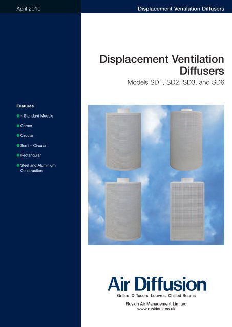
April 2010<br />
<strong><strong>Di</strong>splacement</strong> <strong>Vent</strong>ilation <strong>Di</strong>ffusers<br />
<strong><strong>Di</strong>splacement</strong> <strong>Vent</strong>ilation<br />
<strong>Di</strong>ffusers<br />
Models SD1, SD2, SD3, and SD6<br />
Features<br />
● 4 Standard Models<br />
● Corner<br />
● Circular<br />
● Semi – Circular<br />
● Rectangular<br />
● Steel and Aluminium<br />
Construction<br />
Grilles <strong>Di</strong>ffusers Louvres Chilled Beams<br />
Ruskin <strong>Air</strong> Management Limited<br />
www.ruskinuk.co.uk
<strong><strong>Di</strong>splacement</strong> <strong>Vent</strong>ilation <strong>Di</strong>ffusers<br />
Contents<br />
Page<br />
Introduction Page 2<br />
Model Types Page 2 and 3<br />
Accessories Page 4<br />
Application and Selection Guide Page 5 - 9<br />
<strong>Di</strong>mension Information Page 10 - 11<br />
Ordering Information Page 12<br />
Introduction<br />
Introduction<br />
<strong><strong>Di</strong>splacement</strong> ventilation systems, as the<br />
name implies, rely on a displacement<br />
process of the supply air into the<br />
occupied zone. Typically the supply air is<br />
introduced at low level and at a low<br />
velocity to displace the room air and<br />
provide layers of cool fresh air in the<br />
occupied zone while the extract removes<br />
stale air at high level. Supply air<br />
temperature differentials are normally low<br />
and offer the opportunity to take<br />
advantage of using fresh air based on<br />
“free cooling” for much of the year.<br />
The SD range of displacement diffusers<br />
are ideally suited for use in areas with<br />
high heat loads requiring air volumes up<br />
to 2800 l/s. By using the effects of<br />
convection to lift the supply air from heat<br />
sources, whilst at the same time removing<br />
any pollutants, the air is then extracted at<br />
high level, thus creating an even<br />
temperature, draught free, clean<br />
environment.<br />
Four conventional shapes are available,<br />
Corner, Semi-Circular, Circular and<br />
Rectangular. More unconventional<br />
Trapezoidal and Hexagonal shapes are<br />
also available, on request.<br />
Model SD-1 Corner<br />
Model SD-2 Semi Circular<br />
Model SD-3 Circular<br />
Model SD-6 Rectangular<br />
The diffusers are constructed from steel<br />
and aluminium with the active area<br />
constructed from 5.5mm circular<br />
perforated aluminium giving a 37% free<br />
area or 10mm square perforated<br />
aluminium giving a 69% free area, the<br />
remainder of the unit is from sheet steel.<br />
A complete range of accessories is<br />
available including, spigot dampers,<br />
peripheral or bag filters, dividing rings and<br />
air direction vanes.<br />
The standard colour is White RAL9010<br />
30% gloss although other colours and<br />
finishes are available on special request.<br />
2 www.air-diffusion.co.uk
<strong><strong>Di</strong>splacement</strong> <strong>Vent</strong>ilation <strong>Di</strong>ffusers<br />
Model Types<br />
All model types are available in 6 standard<br />
nominal sizes;<br />
400, 600, 800,1000, 1500 and 2000<br />
and 6 standard heights;<br />
750, 1000, 1250, 1500, 2000 and 2500.<br />
Each model type is available in 6 different<br />
versions,<br />
Supplied with 37% free area 5.5mm<br />
round mesh facia as standard<br />
F1 – Plain without filters,<br />
F2 – Fitted with a cone shaped bag filter,<br />
F5 – With dividing rings.<br />
Supplied with 69% free area 10mm<br />
square mesh facia as standard<br />
F3 – Fitted with a peripheral filter media,<br />
F4 – Fitted with both a cone bag filter and<br />
peripheral filter media,<br />
F6 – Fitted with peripheral filter media and<br />
dividing rings.<br />
Model SD-1 Corner<br />
Model SD-3 Circular<br />
Model SD-2 Semi Circular<br />
Model SD-6 Rectangular<br />
Model Components<br />
1. Perforated Face<br />
2. Bottom Section<br />
3. Circular Inlet Spigot<br />
4. Flap Damper (when requested)<br />
5. Cone Shaped Bag Filter<br />
6. <strong>Di</strong>viding Rings<br />
7. Peripheral Filter Media<br />
8. Top Section<br />
3<br />
8<br />
4<br />
5<br />
7<br />
3<br />
8<br />
4<br />
6<br />
7<br />
1<br />
1<br />
2<br />
2<br />
www.air-diffusion.co.uk 3
<strong><strong>Di</strong>splacement</strong> <strong>Vent</strong>ilation <strong>Di</strong>ffusers<br />
Accessories<br />
<strong>Air</strong> <strong>Di</strong>rection Adjustment Vanes - Model SD-3 Only (Type R1)<br />
<strong>Air</strong> <strong>Di</strong>rection Adjustment Vanes and Control Damper - Model SD-3 Only (Type R2)<br />
Volume control damper opened<br />
Volume control damper closed<br />
4 www.air-diffusion.co.uk
<strong><strong>Di</strong>splacement</strong> <strong>Vent</strong>ilation <strong>Di</strong>ffusers<br />
Application and Selection Guide<br />
Typical Application Layout<br />
Q<br />
0.8m<br />
L WA<br />
Δp<br />
V et<br />
v L<br />
0.8<br />
Q (l/s)<br />
v L (m/s)<br />
v ef<br />
Dt z (K)<br />
Dt L (K)<br />
Dp t (Pa)<br />
<strong>Air</strong> flow rate.<br />
Supplied air velocity at the<br />
throw distance L=0.8 m.<br />
Effective discharge air<br />
velocity.<br />
Temperature difference<br />
between supply and<br />
room air.<br />
Temperature difference air<br />
jet and room temperature.<br />
Pressure drop.<br />
L WA (db(A)) Sound power level.<br />
Codes for Correction Factors in Selection Guide<br />
F1: Plain without filters<br />
F2: Fitted with cone shaped bag filter<br />
F3: Fitted with peripheral filter media<br />
F4: Fitted with with both a cone bag filter and peripheral filter media<br />
F5: With dividing rings<br />
F6: Fitted with peripheral filter media and dividing rings<br />
www.air-diffusion.co.uk 5
<strong><strong>Di</strong>splacement</strong> <strong>Vent</strong>ilation <strong>Di</strong>ffusers<br />
Selection Guide<br />
SD - 1 Technical Data<br />
<strong>Di</strong>agrams to determine the supplied air velocity of the<br />
throw distance L=0.8m<br />
2500<br />
2000<br />
1500<br />
2000<br />
1250<br />
1000<br />
H=750<br />
2500<br />
2000<br />
1500<br />
1500<br />
1250<br />
1000<br />
H=750<br />
2500<br />
2000<br />
1500<br />
1000<br />
1250<br />
1000<br />
H=750<br />
2500<br />
2000<br />
1500<br />
800<br />
1250<br />
1000<br />
H=750<br />
2500<br />
2000<br />
1500<br />
600<br />
1250<br />
1000<br />
H=750<br />
2500<br />
2000<br />
1500<br />
400<br />
1250<br />
1000<br />
H=750<br />
L = 0.8 m 56<br />
0.15 m/s 0.30 m/s<br />
Pressure drop and noise level diagrams<br />
600 1500<br />
1000<br />
size 400 800 1000 2000<br />
Δp t (Pa)<br />
500<br />
400<br />
300<br />
200<br />
100<br />
80<br />
60<br />
40<br />
20<br />
10<br />
8<br />
6<br />
5<br />
4<br />
3<br />
2<br />
1<br />
278 556<br />
833 1111 1389 Q (l/s) 111 167 222 278 556 833 1111 1667 2222 2778<br />
30<br />
Q (l/s)<br />
40<br />
35<br />
45<br />
50<br />
L WA dB (A)<br />
KF Correction Factor Table<br />
Example calculations<br />
Correction Size 750 1000 1250 1500 2000 2500<br />
Dpt 400 1.44 1.00 0.80 0.26 0.16 0.11<br />
for the type 600 1.10 1.00 0.96 0.28 0.26 0.25<br />
F3 800 1.06 1.00 0.97 0.29 0.27 0.27<br />
1000 1.10 1.00 0.96 0.33 0.31 0.30<br />
1500 1.04 1.00 0.98 0.34 0.33 0.33<br />
2000 1.02 1.00 0.99 0.38 0.38 0.37<br />
Dpt 400 0.55 0.51 0.50 0.05 0.04 0.04<br />
for the type 600 0.56 0.51 0.49 0.14 0.13 0.13<br />
F1 800 0.93 0.93 0.93 0.26 0.26 0.26<br />
1000 0.90 0.89 0.89 0.28 0.28 0.28<br />
1500 0.96 0.95 0.95 0.32 0.32 0.32<br />
2000 0.98 0.98 0.98 0.37 0.37 0.37<br />
Dpt 400 2.33 1.42 1.11 0.47 0.28 0.19<br />
for the type 600 1.30 1.11 1.03 0.33 0.28 0.26<br />
F4 800 1.19 1.07 1.02 0.32 0.29 0.28<br />
1000 1.29 1.11 1.02 0.38 0.33 0.31<br />
1500 1.13 1.05 1.01 0.36 0.34 0.34<br />
2000 1.06 1.02 1.01 0.39 0.38 0.38<br />
Size 400 600 800 1000 1500 2000<br />
L(m) 0.214 0.406 0.502 0.718 1.066 1.400<br />
Q = 556 l/s<br />
We select size 1000; H = 1500<br />
A ef = 0.718 x 1.5 x 0.6944 = 0.748 (m 2 )<br />
v ef = Q / (A ef = 0.556 = 0.74 m/s<br />
0.748<br />
L WA = 42 dB(A)<br />
Pressure drop:<br />
Type F3<br />
D pt = from the diagram x KF (for H = 1500) = 230 x 0.33 = 75.9 Pa<br />
Type F1<br />
D pt = from the diagram x KF (for H = 1500) = 230 x 0.28 = 64.4 Pa<br />
Type F4<br />
D pt = from the diagram x KF (for H = 1500) = 230 x 0.38 = 87.4 Pa<br />
Q (l/s) <strong>Air</strong> flow rate<br />
v L (m/s) Supplied air velocity at the throw distance L = 0.8m<br />
D pt (Pa) Pressure drop<br />
L WA (db (A)) Sound power level<br />
Calculation of free area A ef :<br />
A ef = L x H x 0.6944 (m 2 ) L – from the table<br />
A ef = L x H x 0.37 (m 2 ) for the versions F1, F2, and F5 (without filter) and<br />
mantle perforation with round openings.<br />
6 www.air-diffusion.co.uk
<strong><strong>Di</strong>splacement</strong> <strong>Vent</strong>ilation <strong>Di</strong>ffusers<br />
Selection Guide<br />
SD - 2 Technical Data<br />
<strong>Di</strong>agrams to determine the supplied air velocity of the<br />
throw distance L=0.8m<br />
2500<br />
2000<br />
1500<br />
2000<br />
1250<br />
1000<br />
H=750<br />
2500<br />
2000<br />
1500<br />
1500<br />
1250<br />
1000<br />
H=750<br />
2500<br />
2000<br />
1500<br />
1000<br />
1250<br />
1000<br />
H=750<br />
2500<br />
2000<br />
1500<br />
800<br />
1250<br />
1000<br />
H=750<br />
2500<br />
2000<br />
1500<br />
600<br />
1250<br />
1000<br />
H=750<br />
2500<br />
2000<br />
1500<br />
400<br />
1250<br />
1000<br />
H=750<br />
L = 0.8 m<br />
Δp t (Pa)<br />
Pressure drop and noise level diagrams<br />
1000<br />
500<br />
400<br />
300<br />
200<br />
100<br />
80<br />
60<br />
40<br />
20<br />
10<br />
8<br />
6<br />
5<br />
4<br />
3<br />
2<br />
30<br />
35<br />
40<br />
600<br />
size 400 800<br />
1<br />
278 556 833 1111 1389 1667 2222 2778 Q (l/s) 111 167 222 278 556 833 1111 1667 2222 2778<br />
Q (l/s)<br />
45<br />
L WA<br />
dB (A)<br />
50<br />
55<br />
1000<br />
1500<br />
2000<br />
0.15 m/s 0.30 m/s<br />
KF Correction Factor Table<br />
Example calculations<br />
Correction Size 750 1000 1250 1500 2000 2500<br />
Dpt 400 1.43 1.00 0.81 0.28 0.18 0.13<br />
for the type 600 1,15 1.00 0.93 0.32 0.29 0.27<br />
F3 800 1.08 1.00 0.97 0.35 0.33 0.33<br />
1000 1.30 1.00 0.87 0.33 0.26 0.23<br />
1500 1.13 1.00 0.94 0.36 0.33 0.32<br />
2000 1.07 1.00 0.97 0.38 0.36 0.36<br />
Dpt 400 0.56 0.52 0.51 0.07 0.07 0.06<br />
for the type 600 0.58 0.84 0.83 0.25 0.25 0.25<br />
F1 800 0.92 0.92 0.91 0.32 0.31 0.31<br />
1000 0.69 0.67 0.66 0.18 0.18 0.18<br />
1500 0.87 0.86 0.86 0.30 0.30 0.30<br />
2000 0.93 0.92 0.92 0.35 0.34 0.34<br />
Dpt 400 2.30 1.48 1.11 0.19 0.29 0.21<br />
for the type 600 1.44 1.16 1.04 0.39 0.33 0.30<br />
F4 800 1.23 1.08 1.02 0.39 0.35 0.34<br />
1000 1.91 1.33 1.08 0.47 0.34 0.28<br />
1500 1.38 1.14 1.03 0.42 0.36 0.34<br />
2000 1.21 1.08 1.02 0.41 0.36 0.37<br />
Size 400 600 800 1000 1500 2000<br />
L(m) 0.598 0.920 1.228 1.550 2.334 3.120<br />
Q = 556 l/s<br />
We select size 600; H = 1500<br />
A ef = 0.92 x 1.5 x 0.6944 = 0.958 (m 2 )<br />
v ef = Q / A ef = 0.556 = 0.58 m/s<br />
0.958<br />
L WA = 45 dB(A)<br />
Pressure drop:<br />
Type F3<br />
D pt = from the diagram x KF (for H = 1500) = 60 x 0.32 = 19.2 Pa<br />
Type F1<br />
D pt = from the diagram x KF (for H = 1500) = 60 x 0.25 = 15.0 Pa<br />
Type F4<br />
D pt = from the diagram x KF (for H = 1500) = 60 x 0.39 = 19.5 Pa<br />
Q (l/s) <strong>Air</strong> flow rate<br />
v L (m/s) Supplied air velocity at the throw distance L = 0.8m<br />
D pt (Pa) Pressure drop<br />
L WA (db (A)) Sound power level<br />
Calculation of free area A ef :<br />
A ef = L x H x 0.6944 (m 2 ) L – from the table<br />
A ef = L x H x 0.37 (m 2 ) for the versions F1, F2, and F5 (without filter) and<br />
mantle perforation with round openings.<br />
www.air-diffusion.co.uk 7
<strong><strong>Di</strong>splacement</strong> <strong>Vent</strong>ilation <strong>Di</strong>ffusers<br />
Selection Guide<br />
SD - 3 Technical Data<br />
<strong>Di</strong>agrams to determine the supplied air velocity of the<br />
throw distance L=0.8m<br />
2500<br />
2000<br />
1500<br />
2000<br />
1250<br />
1000<br />
H=750<br />
2500<br />
2000<br />
1500<br />
1500<br />
1250<br />
1000<br />
H=750<br />
2500<br />
2000<br />
1500<br />
1000<br />
1250<br />
1000<br />
H=750<br />
2500<br />
2000<br />
1500<br />
800<br />
1250<br />
1000<br />
H=750<br />
2500<br />
2000<br />
1500<br />
600<br />
1250<br />
1000<br />
H=750<br />
2500<br />
2000<br />
1500<br />
400<br />
1250<br />
1000<br />
H=750<br />
L = 0.8 m<br />
Δp t (Pa)<br />
Pressure drop and noise level diagrams<br />
1000<br />
500<br />
400<br />
300<br />
200<br />
100<br />
80<br />
60<br />
40<br />
20<br />
10<br />
8<br />
6<br />
5<br />
4<br />
3<br />
2<br />
1<br />
556 1111 1667 2222 2778 3889 5000 6111 Q (l/s) 111 167 222 278 556 833 1111 1667 2222 2778<br />
Q (l/s)<br />
25<br />
30<br />
35<br />
40<br />
L WA<br />
dB (A)<br />
size<br />
45<br />
400<br />
600<br />
800<br />
1000<br />
1500<br />
2000<br />
50<br />
0.15 m/s 0.30 m/s<br />
KF Correction Factor Table<br />
Example calculations<br />
Correction Size 750 1000 1250 1500 2000 2500<br />
Dpt 400 1.47 1.00 0.79 0.36 0.26 0.21<br />
for the type 600 1.11 1.00 0.95 0.55 0.52 0.51<br />
F3 800 1.05 1.00 0.98 0.61 0.59 0.59<br />
1000 1.05 1.00 0.98 0.19 0.18 0.17<br />
1500 1.02 1.00 0.99 0.22 0.21 0.21<br />
2000 1.01 1.00 1.00 0.23 0.22 0.22<br />
Dpt 400 0.51 0.48 0.46 0.14 0.13 0.13<br />
for the type 600 0.88 0.87 0.87 0.49 0.49 0.49<br />
F1 800 0.95 0.94 0.94 0.58 0.58 0.58<br />
1000 0.95 0.95 0.95 0.17 0.17 0.17<br />
1500 0.98 0.98 0.98 0.21 0.21 0.21<br />
2000 0.99 0.99 0.99 0.22 0.22 0.22<br />
Dpt 400 2.42 1.52 1.12 0.59 0.38 0.29<br />
for the type 600 1.34 1.13 1.03 0.60 0.55 0.53<br />
F4 800 1.15 1.06 1.01 0.63 0.61 0.60<br />
1000 1.14 1.05 1.01 0.21 0.19 0.18<br />
1500 1.05 1.02 1.00 0.22 0.22 0.21<br />
2000 1.03 1.01 1.00 0.23 0.23 0.22<br />
Calculation of free area A ef :<br />
A ef = A x π x H x 0.6944 (m 2 ) A – size (m)<br />
A ef = A x π x H x 0.37 (m 2 ) for the versions F1, F2, and F5 (without filter)<br />
and mantle perforation with round openings.<br />
Q = 1111 l/s<br />
We select size 1000; H = 750<br />
A ef = 1 x π x 0.75 x 0.6944 = 1.64 (m 2 )<br />
v ef = Q / A ef = 1.111 = 0.68 m/s<br />
1.64<br />
L WA = 37 dB(A)<br />
Pressure drop:<br />
Type F3<br />
D pt = from the diagram x KF (for H = 750) = 60 x 1.05 = 63.0 Pa<br />
Type F1<br />
D pt = from the diagram x KF (for H = 750) = 60 x 0.95 = 57.0 Pa<br />
Type F4<br />
D pt = from the diagram x KF (for H = 750) = 60 x 1.14 = 68.4 Pa<br />
Q (l/s) <strong>Air</strong> flow rate<br />
v L (m/s) Supplied air velocity at the throw distance L = 0.8m<br />
D pt (Pa) Pressure drop<br />
L WA (db (A)) Sound power level<br />
8 www.air-diffusion.co.uk
<strong><strong>Di</strong>splacement</strong> <strong>Vent</strong>ilation <strong>Di</strong>ffusers<br />
Selection Guide<br />
SD - 6 Technical Data<br />
<strong>Di</strong>agrams to determine the supplied air velocity of the<br />
throw distance L=0.8m<br />
Δp t<br />
(Pa)<br />
Pressure drop and noise level diagrams<br />
size 400 400 400<br />
1000<br />
2500<br />
1000<br />
2000<br />
1500<br />
2000<br />
1250<br />
500<br />
1500<br />
1000<br />
400<br />
H=750<br />
2500<br />
300<br />
2000<br />
2000<br />
1500<br />
200<br />
1500<br />
1250<br />
1000<br />
H=750<br />
100<br />
2500<br />
2000<br />
80<br />
1500<br />
60<br />
1000<br />
1250<br />
50<br />
1000<br />
40<br />
H=750<br />
45<br />
2500<br />
2000<br />
1500<br />
20<br />
40<br />
800<br />
1250<br />
1000<br />
35<br />
H=750<br />
10<br />
2500<br />
8<br />
2000<br />
30<br />
1500<br />
6<br />
600<br />
1250<br />
5<br />
25<br />
1000<br />
4<br />
H=750<br />
2500<br />
3<br />
2000<br />
1500<br />
2<br />
400<br />
1250<br />
1000<br />
H=750<br />
1<br />
L = 0.8 m Q (l/s) 556 833<br />
1111 1667 2083 111 167 222 278 556 833 1111 1667 2222 2778<br />
Q (l/s)<br />
L WA<br />
dB (A)<br />
0.15 m/s 0.30 m/s<br />
KF Correction Factor Table<br />
Example calculations<br />
Correction Size 750 1000 1250 1500 2000 2500<br />
Dpt 400 1.11 1.00 0.95 0.93 0.90 0.89<br />
for the type 600 1.14 1.00 0.94 0.90 0.87 0.86<br />
F3 800 1.18 1.00 0.92 0.88 0.83 0.82<br />
1000 1.22 1.00 0.90 0.85 0.79 0.77<br />
1500 1.18 1.00 0.92 0.88 0.84 0.82<br />
2000 1.17 1.00 0.92 0.89 0.85 0.83<br />
Dpt 400 0.89 0.88 0.88 0.88 0.87 0.87<br />
for the type 600 0.85 0.84 0.84 0.84 0.83 0.83<br />
F1 800 0.81 0.80 0.79 0.79 0.79 0.78<br />
1000 0.77 0.75 0.74 0.74 0.74 0.83<br />
1500 0.81 0.80 0.79 0.79 0.79 0.78<br />
2000 0.83 0.81 0.81 0.80 0.80 0.73<br />
Dpt 400 1.32 1.12 1.03 0.98 0.93 0.79<br />
for the type 600 1.42 1.16 1.04 0.97 0.91 0.80<br />
F4 800 1.55 1.20 1.05 0.96 0.88 0.91<br />
1000 1.68 1.25 1.06 0.95 0.85 0.88<br />
1500 1.55 1.20 1.05 0.96 0.88 0.85<br />
2000 1.51 1.19 1.04 0.97 0.89 0.86<br />
Calculation of free area A ef :<br />
A ef = A x H x 0.6944 (m 2 ) A – Size (m)<br />
A ef = A x H x 0.37 (m 2 ) for the versions F1, F2, and F5 (without filter) and<br />
mantle perforation with round openings.<br />
Q = 1111 l/s<br />
We select size 2000; H = 1250<br />
A ef = 2 x 1.25 x 0.6944 = 1.74 (m 2 )<br />
v ef = Q / A ef = 1.111 = 0.64 m/s<br />
1.74<br />
L WA = 48 dB(A)<br />
Pressure drop:<br />
Type F3<br />
D pt = from the diagram x KF (for H = 1250) = 45 x 0.92 = 41.4 Pa<br />
Type F1<br />
D pt = from the diagram x KF (for H = 1250) = 45 x 0.81 = 36.4 Pa<br />
Type F4<br />
D pt = from the diagram x KF (for H = 1250) = 45 x 1.04 = 46.8 Pa<br />
Q (l/s) <strong>Air</strong> flow rate<br />
v L (m/s) Supplied air velocity at the throw distance L = 0.8m<br />
D pt (Pa) Pressure drop<br />
L WA (db (A)) Sound power level<br />
www.air-diffusion.co.uk 9
<strong><strong>Di</strong>splacement</strong> <strong>Vent</strong>ilation <strong>Di</strong>ffusers<br />
<strong>Di</strong>mensions<br />
SD-1 Corner<br />
SD-2 Semi Circular<br />
A<br />
B<br />
C<br />
A<br />
ØD<br />
60<br />
ØD<br />
H<br />
H<br />
B<br />
C<br />
60<br />
Size A B C ØD H<br />
400 283 180 100 123 750<br />
600 424 275 135 148 1000<br />
800 566 300 150 178 1250<br />
1000 707 400 200 198 1500<br />
1500 1061 450 220 248 2000<br />
2000 1414 700 350 298 2500<br />
Size A B C ØD<br />
400 400 320 150 178<br />
600 600 470 230 198<br />
800 800 570 250 248<br />
1000 1000 620 280 298<br />
1500 1500 870 350 348<br />
2000 2000 1120 430 398<br />
SD-3 Circular<br />
ØD<br />
60 A<br />
Size A ØD H<br />
400 400 248 750<br />
600 600 298 1000<br />
800 800 348 1250<br />
1000 1000 398 1500<br />
1500 1500 498 2000<br />
2000 2000 548 2500<br />
H<br />
10 www.air-diffusion.co.uk
<strong><strong>Di</strong>splacement</strong> <strong>Vent</strong>ilation <strong>Di</strong>ffusers<br />
<strong>Di</strong>mensions<br />
SD-6 Rectangular<br />
A<br />
ØD<br />
60 B<br />
Size A B ØD H<br />
400 400 200 148 750<br />
600 600 250 178 1000<br />
800 800 300 198 1250<br />
1000 1000 350 248 1500<br />
1500 1500 400 298 2000<br />
2000 2000 450 313 2500<br />
H<br />
Ordering Information<br />
Example<br />
Type Version Regulation (Standard) Size (Standard) Height<br />
SD-3 F1 R1 400 750<br />
SD-1 Corner<br />
SD-2 Semi-cylindrical<br />
SD-3 Cylindrical<br />
SD-6 Rectangular<br />
F1 – without filters.<br />
F2 – with the filter bag.<br />
F3 – with the peripheral filter.<br />
F4 – with the filter bag and the<br />
peripheral filter.<br />
F5 – With dividing rings without filters.<br />
R1 – Regulation with<br />
blades (available with<br />
Type SD-3)<br />
R2 – Regulation with a<br />
flow control damper<br />
(available with Type<br />
SD-3).<br />
400<br />
600<br />
800<br />
1000<br />
1500<br />
2000<br />
750<br />
1000<br />
1250<br />
1500<br />
2000<br />
2500<br />
F6 – With dividing rings and<br />
peripheral filter.<br />
Note:<br />
Please refer to page 3 for type of<br />
perforated mesh facia.<br />
Important Note: All orders must be addressed to <strong>Air</strong> <strong>Di</strong>ffusion, Ruskin <strong>Air</strong> Management Limited.<br />
www.air-diffusion.co.uk 11
<strong><strong>Di</strong>splacement</strong> <strong>Vent</strong>ilation <strong>Di</strong>ffusers<br />
Ruskin <strong>Air</strong> Management Limited<br />
is a BS EN ISO 9000 registered<br />
company.<br />
The statements made in this brochure or by our<br />
representatives in consequence of any enquiries<br />
arising out of this document are given for information<br />
purposes only. They are not intended to have any<br />
legal effect and the company is not to be regarded<br />
as bound thereby. The company will only accept<br />
obligations which are expressly negotiated for and<br />
agreed and incorporated into a written agreement<br />
made with its customers.<br />
Due to a policy of continuous product development<br />
the specification and details contained herein are<br />
subject to alteration without prior notice.<br />
Comprehensive and detailed information<br />
is available for all <strong>Air</strong> <strong>Di</strong>ffusion products.<br />
Visit our website at www.air-diffusion.co.uk<br />
Ruskin <strong>Air</strong> Management Limited<br />
Stourbridge Road, Bridgnorth, Shropshire,<br />
WV15 5BB England.<br />
Tel: 01746 761921<br />
Fax: 01746 760127<br />
Email: sales@air-diffusion.co.uk<br />
Website: www.air-diffusion.co.uk<br />
BROCHURE PRODUCTION www.geoffstrange.co.uk