Chapter 10 Suspension and steering
Chapter 10 Suspension and steering
Chapter 10 Suspension and steering

You also want an ePaper? Increase the reach of your titles
YUMPU automatically turns print PDFs into web optimized ePapers that Google loves.
<strong>10</strong>•1<br />
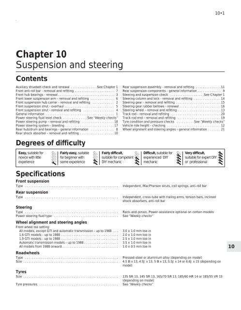
<strong>Chapter</strong> <strong>10</strong><br />
<strong>Suspension</strong> <strong>and</strong> <strong>steering</strong><br />
Contents<br />
Auxiliary drivebelt check <strong>and</strong> renewal . . . . . . . . . . . . . . .See <strong>Chapter</strong> 1<br />
Front anti-roll bar - removal <strong>and</strong> refitting . . . . . . . . . . . . . . . . . . . . . . 7<br />
Front hub bearings - renewal . . . . . . . . . . . . . . . . . . . . . . . . . . . . . . . 3<br />
Front lower suspension arm - removal <strong>and</strong> refitting . . . . . . . . . . . . . 6<br />
Front suspension hub carrier - removal <strong>and</strong> refitting . . . . . . . . . . . . 2<br />
Front suspension strut - overhaul . . . . . . . . . . . . . . . . . . . . . . . . . . . 5<br />
Front suspension strut - removal <strong>and</strong> refitting . . . . . . . . . . . . . . . . . 4<br />
General information . . . . . . . . . . . . . . . . . . . . . . . . . . . . . . . . . . . . . . 1<br />
Power <strong>steering</strong> fluid level check . . . . . . . . . . . . . .See “Weekly checks”<br />
Power <strong>steering</strong> pump - removal <strong>and</strong> refitting . . . . . . . . . . . . . . . . . . 18<br />
Power <strong>steering</strong> system - bleeding . . . . . . . . . . . . . . . . . . . . . . . . . . . 17<br />
Rear hub/drum <strong>and</strong> bearings - general information . . . . . . . . . . . . . 8<br />
Rear shock absorber - removal <strong>and</strong> refitting . . . . . . . . . . . . . . . . . . . <strong>10</strong><br />
Degrees of difficulty<br />
Easy, suitable for<br />
novice with little<br />
experience<br />
1<br />
Specifications<br />
Fairly easy, suitable<br />
for beginner with<br />
some experience<br />
Front suspension<br />
Type . . . . . . . . . . . . . . . . . . . . . . . . . . . . . . . . . . . . . . . . . . . . . . . . . . . .<br />
Rear suspension<br />
Type . . . . . . . . . . . . . . . . . . . . . . . . . . . . . . . . . . . . . . . . . . . . . . . . . . . .<br />
Steering<br />
Type . . . . . . . . . . . . . . . . . . . . . . . . . . . . . . . . . . . . . . . . . . . . . . . . . . . .<br />
Power <strong>steering</strong> fluid type . . . . . . . . . . . . . . . . . . . . . . . . . . . . . . . . . . . .<br />
Wheel alignment <strong>and</strong> <strong>steering</strong> angles<br />
Front wheel toe setting:<br />
All models, except GTI <strong>and</strong> automatic transmission - up to 1988 . . . 3.0 ± 1.0 mm toe-in<br />
1.6 GTI models - up to 1988 . . . . . . . . . . . . . . . . . . . . . . . . . . . . . . . . 2.0 ± 1.0 mm toe-in<br />
1.9 GTI models - up to 1988 . . . . . . . . . . . . . . . . . . . . . . . . . . . . . . . . 2.5 ± 1.0 mm toe-in<br />
Automatic transmission models - up to 1988 . . . . . . . . . . . . . . . . . . . 3.5 ± 1.0 mm toe-in<br />
All models from 1988 onward . . . . . . . . . . . . . . . . . . . . . . . . . . . . . . . 1.0 ± 0.5 mm toe-in<br />
Roadwheels<br />
Type . . . . . . . . . . . . . . . . . . . . . . . . . . . . . . . . . . . . . . . . . . . . . . . . . . . .<br />
Size . . . . . . . . . . . . . . . . . . . . . . . . . . . . . . . . . . . . . . . . . . . . . . . . . . . . .<br />
2<br />
Fairly difficult,<br />
suitable for competent<br />
DIY mechanic<br />
Rear suspension assembly - removal <strong>and</strong> refitting . . . . . . . . . . . . . . 11<br />
Rear suspension components - general information . . . . . . . . . . . . . 9<br />
Steering <strong>and</strong> suspension check . . . . . . . . . . . . . . . . . . .See <strong>Chapter</strong> 1<br />
Steering column <strong>and</strong> lock - removal <strong>and</strong> refitting . . . . . . . . . . . . . . . 14<br />
Steering gear - removal <strong>and</strong> refitting . . . . . . . . . . . . . . . . . . . . . . . . . 15<br />
Steering gear rubber bellows - renewal . . . . . . . . . . . . . . . . . . . . . . . 16<br />
Steering wheel - removal <strong>and</strong> refitting . . . . . . . . . . . . . . . . . . . . . . . . 13<br />
Track rod - removal <strong>and</strong> refitting . . . . . . . . . . . . . . . . . . . . . . . . . . . . 20<br />
Track rod end - removal <strong>and</strong> refitting . . . . . . . . . . . . . . . . . . . . . . . . 19<br />
Tyre condition <strong>and</strong> pressure checks . . . . . . . . . .See “Weekly checks”<br />
Vehicle ride height - checking . . . . . . . . . . . . . . . . . . . . . . . . . . . . . . 12<br />
Wheel alignment <strong>and</strong> <strong>steering</strong> angles - general information . . . . . . . 21<br />
Difficult, suitable for<br />
experienced DIY<br />
mechanic<br />
Very difficult,<br />
suitable for expert DIY<br />
or professional<br />
Independent, MacPherson struts, coil springs, anti-roll bar<br />
Independent, cross-tube with trailing arms, torsion bars, inclined<br />
shock absorbers, anti-roll bar<br />
Rack-<strong>and</strong>-pinion. Power-assistance optional on certain models<br />
See “Weekly checks”<br />
Pressed-steel or aluminium alloy (depending on model)<br />
4.5 B x 13, 4.5J x 13, 5 B x 13, 5.5J x 14 or 6.6J x 15 (depending on<br />
model)<br />
Tyres<br />
Size . . . . . . . . . . . . . . . . . . . . . . . . . . . . . . . . . . . . . . . . . . . . . . . . . . . . . 135 SR 13, 145 SR 13, 165/70 SR 13, 185/60 HR 14 or 185/55 VR 15<br />
(depending on model)<br />
Tyre pressures . . . . . . . . . . . . . . . . . . . . . . . . . . . . . . . . . . . . . . . . . . . . See “Weekly checks”<br />
3<br />
4<br />
5<br />
<strong>10</strong>
<strong>10</strong>•2 <strong>Suspension</strong> <strong>and</strong> <strong>steering</strong><br />
Torque wrench settings Nm lbf ft<br />
Front suspension<br />
Driveshaft/hub nut:<br />
Non-GTI models . . . . . . . . . . . . . . . . . . . . . . . . . . . . . . . . . . . . . . . . . 250 185<br />
GTI models . . . . . . . . . . . . . . . . . . . . . . . . . . . . . . . . . . . . . . . . . . . . . 260 192<br />
Automatic transmission models . . . . . . . . . . . . . . . . . . . . . . . . . . . . . 265 196<br />
Strut top mounting . . . . . . . . . . . . . . . . . . . . . . . . . . . . . . . . . . . . . . . . . 12 9<br />
Shock absorber piston rod nut:<br />
Self-locking type . . . . . . . . . . . . . . . . . . . . . . . . . . . . . . . . . . . . . . . . . 45 33<br />
Crimped type . . . . . . . . . . . . . . . . . . . . . . . . . . . . . . . . . . . . . . . . . . . 70 52<br />
Strut clamp bolt . . . . . . . . . . . . . . . . . . . . . . . . . . . . . . . . . . . . . . . . . . . 58 43<br />
Anti-roll bar clamp . . . . . . . . . . . . . . . . . . . . . . . . . . . . . . . . . . . . . . . . . 35 26<br />
Anti-roll bar end (non-GTI models) . . . . . . . . . . . . . . . . . . . . . . . . . . . . . 75 55<br />
Lower balljoint clamp bolt:<br />
Manual transmission models . . . . . . . . . . . . . . . . . . . . . . . . . . . . . . . 35 26<br />
Automatic transmission models . . . . . . . . . . . . . . . . . . . . . . . . . . . . . 45 33<br />
Anti-roll bar guide bar . . . . . . . . . . . . . . . . . . . . . . . . . . . . . . . . . . . . . . . 30 22<br />
Lower suspension arm pivot bolt . . . . . . . . . . . . . . . . . . . . . . . . . . . . . . 35 26<br />
Anti-roll bar end (GTI models) . . . . . . . . . . . . . . . . . . . . . . . . . . . . . . . . . 58 43<br />
Lower suspension arm rear pivot bolt (GTI models) . . . . . . . . . . . . . . . . 78 58<br />
Rear suspension<br />
Shock absorber upper mounting . . . . . . . . . . . . . . . . . . . . . . . . . . . . . . 75 55<br />
Shock absorber lower mounting . . . . . . . . . . . . . . . . . . . . . . . . . . . . . . 118 87<br />
Anti-roll bar arm . . . . . . . . . . . . . . . . . . . . . . . . . . . . . . . . . . . . . . . . . . . 35 26<br />
Torsion bar plug . . . . . . . . . . . . . . . . . . . . . . . . . . . . . . . . . . . . . . . . . . . 20 15<br />
<strong>Suspension</strong> top mountings . . . . . . . . . . . . . . . . . . . . . . . . . . . . . . . . . . . 45 33<br />
<strong>Suspension</strong> front mounting pivot bolt . . . . . . . . . . . . . . . . . . . . . . . . . . 80 59<br />
Steering<br />
Steering gear mounting bolts . . . . . . . . . . . . . . . . . . . . . . . . . . . . . . . . . 35 26<br />
Power <strong>steering</strong> fluid pipe unions . . . . . . . . . . . . . . . . . . . . . . . . . . . . . . 23 17<br />
Column-to-pinion clamp bolt . . . . . . . . . . . . . . . . . . . . . . . . . . . . . . . . . 15 11<br />
Track rod end balljoint nut . . . . . . . . . . . . . . . . . . . . . . . . . . . . . . . . . . . 35 26<br />
Track rod inner joint . . . . . . . . . . . . . . . . . . . . . . . . . . . . . . . . . . . . . . . . 50 37<br />
Steering wheel nut . . . . . . . . . . . . . . . . . . . . . . . . . . . . . . . . . . . . . . . . . 30 22<br />
Roadwheels<br />
Roadwheel bolts (all wheel types)* . . . . . . . . . . . . . . . . . . . . . . . . . . . . . 85 63<br />
*On alloy wheels, oil the ends of the bolt threads over a maximum length of <strong>10</strong> mm before fitting.<br />
1 General information<br />
The front suspension is of independent<br />
type; incorporating MacPherson struts with<br />
coil springs <strong>and</strong> integral shock absorbers. On<br />
non-GTI models the lower suspension arm<br />
movement is controlled by the anti-roll bar,<br />
but on GTI models the arm has two inner pivot<br />
points <strong>and</strong> the anti-roll bar operates<br />
separately on the struts.<br />
The rear suspension is also of independent<br />
type; incorporating a cross-tube with trailing<br />
arms set in each end <strong>and</strong> supported on<br />
needle or plain bearings. Torsion bars are<br />
fitted to the trailing arms <strong>and</strong>, on certain<br />
models, an anti-roll bar located inside the<br />
cross-tube stabilises the car when cornering.<br />
The telescopic shock absorbers are inclined<br />
with their top mountings attached to the<br />
suspension side-members.<br />
The <strong>steering</strong> system is of rack <strong>and</strong> pinion<br />
type with side track rods connected to the<br />
hub carriers by track rod end balljoints.<br />
Further balljoints on the inner ends of the<br />
track rods are screwed into the rack. Powerassisted<br />
<strong>steering</strong> is available as an option on<br />
later models. Power assistance is derived<br />
from a hydraulic pump, belt-driven from the<br />
crankshaft pulley.<br />
The <strong>steering</strong> column incorporates a single<br />
universal joint at its lower end connected to<br />
an intermediate shaft which also incorporates<br />
a universal joint at its connection to the pinion<br />
on the <strong>steering</strong> gear. The <strong>steering</strong> column is<br />
angled to prevent direct movement into the<br />
passenger compartment in the event of a front<br />
end impact.<br />
2 Front suspension hub carrier<br />
- removal <strong>and</strong> refitting<br />
4<br />
Removal<br />
1 Fully apply the h<strong>and</strong>brake then, where<br />
possible, remove the front wheel centre trim.<br />
Tap up the staking securing the hub nut to the<br />
driveshaft groove or, on later models, extract<br />
the R-clip <strong>and</strong> withdraw the locking collar<br />
(see illustration). Using a socket <strong>and</strong> a long<br />
extension bar, slacken the hub nut. On<br />
models without a centre trim, the hub nut<br />
must be loosened after removing the front<br />
wheel. Do not apply the footbrake when<br />
loosening the nut as damage can occur to the<br />
brake disc retaining screws.<br />
2 Chock the rear wheels then jack up the<br />
front of the car <strong>and</strong> support it on axle st<strong>and</strong>s<br />
(see “Jacking <strong>and</strong> vehicle support”). Remove<br />
the front roadwheel.<br />
2.1 R-clip <strong>and</strong> locking collar fitted to hub<br />
nut on later models
<strong>Suspension</strong> <strong>and</strong> <strong>steering</strong> <strong>10</strong>•3<br />
2.4a Unscrew the lower balljoint clamp<br />
bolt . . .<br />
2.4b . . . <strong>and</strong> pull the suspension arm down<br />
from the hub carrier<br />
2.11 Unscrew the clamp bolt securing the<br />
lower end of the suspension strut to the<br />
hub carrier<br />
3 If the hub nut has yet to be loosened,<br />
fabricate a tool from two lengths of steel strip<br />
(one long, one short) <strong>and</strong> a nut <strong>and</strong> bolt; the<br />
nut <strong>and</strong> bolt form the pivot of a forked tool.<br />
Bolt the tool to the hub flange using two wheel<br />
bolts, <strong>and</strong> hold the tool to prevent the hub<br />
from rotating (see <strong>Chapter</strong> 8, Section 2).<br />
Slacken the hub nut using a socket <strong>and</strong> a long<br />
extension bar.<br />
4 Unscrew the clamp bolt securing the front<br />
suspension lower balljoint to the bottom of the<br />
hub carrier then pull the lower suspension arm<br />
down from the carrier (see illustrations).<br />
5 Recover the balljoint guard plate, where<br />
fitted.<br />
6 Turn the front wheels to full right-h<strong>and</strong> lock<br />
(left-h<strong>and</strong> hub carrier), or full left-h<strong>and</strong> lock<br />
(right-h<strong>and</strong> hub carrier) <strong>and</strong> remove the hub<br />
nut <strong>and</strong>, where fitted, the washer. Note that a<br />
new hub nut will be required for refitting.<br />
7 Pull the hub carrier outwards <strong>and</strong> at the<br />
same time withdraw the outer end of the<br />
driveshaft from the hub. Suitably support or<br />
tie up the driveshaft in a near horizontal<br />
position to avoid damage to the inner CV<br />
joints.<br />
8 Unbolt the disc brake caliper from the hub<br />
carrier <strong>and</strong> either place it on a st<strong>and</strong> or tie it to<br />
one side.<br />
9 Remove the two screws <strong>and</strong> withdraw the<br />
brake disc.<br />
<strong>10</strong> Unscrew the nut <strong>and</strong> use a balljoint<br />
removal tool to separate the track rod end<br />
balljoint from the hub carrier <strong>steering</strong> arm.<br />
11 Unscrew the clamp bolt securing the<br />
lower end of the suspension strut to the hub<br />
carrier (see illustration). Spread the slot on<br />
the hub carrier using a screwdriver or suitable<br />
wedge <strong>and</strong> slide the carrier from the bottom<br />
of the strut. Remove the hub carrier from the<br />
car.<br />
Refitting<br />
12 Refitting is a reversal of removal, but refer<br />
to <strong>Chapter</strong>s 8 <strong>and</strong> 9 respectively when<br />
refitting the driveshaft <strong>and</strong> disc brake caliper.<br />
3 Front hub bearings - renewal<br />
4<br />
Note: The bearing is a sealed, pre-adjusted<br />
<strong>and</strong> pre-lubricated, double-row ball type, <strong>and</strong><br />
is intended to last the car’s entire service life<br />
without maintenance or attention. Never<br />
overtighten the driveshaft nut beyond the<br />
specified torque wrench setting in an attempt<br />
to “adjust” the bearing.<br />
Note: A press will be required to dismantle<br />
<strong>and</strong> rebuild the assembly; if such a tool is not<br />
available, a large bench vice <strong>and</strong> spacers<br />
(such as large sockets) will serve as an<br />
adequate substitute. The bearing’s inner races<br />
are an interference fit on the hub; if the inner<br />
race remains on the hub when it is pressed<br />
out of the hub carrier, a knife-edged bearing<br />
puller will be required to remove it. A new<br />
bearing retaining circlip must be used on<br />
refitting.<br />
1 Remove the hub carrier assembly as<br />
described in Section 2.<br />
2 Support the hub carrier securely on blocks<br />
or in a vice. Using a tubular spacer which<br />
bears only on the inner end of the hub flange,<br />
press the hub flange out of the bearing. If the<br />
bearing’s outboard inner race remains on the<br />
hub, remove it using a bearing puller (see note<br />
above).<br />
3 Extract the bearing retaining circlip from the<br />
inner end of the hub carrier assembly (see<br />
illustration).<br />
3.3 Front hub bearing retaining circlip<br />
(arrowed)<br />
4 Where necessary, refit the inner race back<br />
in position over the ball cage, <strong>and</strong> securely<br />
support the inner face of the hub carrier.<br />
Using a tubular spacer which bears only on<br />
the inner race, press the complete bearing<br />
assembly out of the hub carrier.<br />
5 Thoroughly clean the hub <strong>and</strong> hub carrier,<br />
removing all traces of dirt <strong>and</strong> grease, <strong>and</strong><br />
polish away any burrs or raised edges which<br />
might hinder reassembly. Check both for<br />
cracks or any other signs of wear or damage,<br />
<strong>and</strong> renew them if necessary. Renew the<br />
circlip, regardless of its apparent condition.<br />
6 On reassembly, apply a light film of oil to<br />
the bearing outer race <strong>and</strong> hub flange shaft, to<br />
aid installation of the bearing.<br />
7 Securely support the hub carrier, <strong>and</strong> locate<br />
the bearing in the hub. Press the bearing fully<br />
into position, ensuring that it enters the hub<br />
squarely, using a tubular spacer which bears<br />
only on the bearing outer race.<br />
8 Once the bearing is correctly seated,<br />
secure the bearing in position with the new<br />
circlip, ensuring that it is correctly located in<br />
the groove in the hub carrier.<br />
9 Securely support the outer face of the hub<br />
flange, <strong>and</strong> locate the hub carrier bearing<br />
inner race over the end of the hub flange.<br />
Press the bearing onto the hub, using a<br />
tubular spacer which bears only on the inner<br />
race of the hub bearing, until it seats against<br />
the hub shoulder. Check that the hub flange<br />
rotates freely, <strong>and</strong> wipe off any excess oil or<br />
grease.<br />
<strong>10</strong> Refit the hub carrier assembly as<br />
described in Section 2.<br />
4 Front suspension strut -<br />
removal <strong>and</strong> refitting<br />
4<br />
Removal<br />
1 Before raising the car it is recommended<br />
that a retaining tool is fitted to the coil spring<br />
to hold the spring in a semi-compressed<br />
state. This will provide sufficient clearance to<br />
enable the strut to be withdrawn from the hub<br />
carrier. Peugeot garages use two special<br />
cables inserted through the holes at the top of<br />
<strong>10</strong>
<strong>10</strong>•4 <strong>Suspension</strong> <strong>and</strong> <strong>steering</strong><br />
5 Front suspension strut -<br />
overhaul 4<br />
4.1 Coil spring compressors fitted to strut<br />
spring<br />
the front suspension tower <strong>and</strong> engaged with<br />
further holes in the bottom coil spring seat. If<br />
available use these, otherwise fit universal coil<br />
spring compressors (see illustration). Do not<br />
attempt to use any makeshift tool, as<br />
considerable damage could occur if the<br />
spring breaks free. To fit either type of tool it<br />
will be necessary to turn the front wheel to full<br />
lock in alternate directions.<br />
2 Loosen, but do not remove, the three strut<br />
top mounting nuts (see illustration).<br />
3 Chock the rear wheels then jack up the<br />
front of the car <strong>and</strong> support it on axle st<strong>and</strong>s<br />
(see “Jacking <strong>and</strong> vehicle support”). Remove<br />
the relevant front roadwheel.<br />
4 On GTI models, unscrew the nut <strong>and</strong><br />
disconnect the anti-roll bar link from the strut.<br />
4.2 Front suspension top mounting nuts<br />
5 Unscrew the clamp bolt securing the lower<br />
end of the strut to the hub carrier. Spread the<br />
slot on the hub carrier using a screwdriver or<br />
suitable wedge, push the suspension arm<br />
down, <strong>and</strong> slide the carrier from the bottom of<br />
the strut.<br />
6 Support the strut then unscrew the top<br />
mounting nuts <strong>and</strong> withdraw it from under the<br />
wheel arch. Recover the washers.<br />
Refitting<br />
7 Refitting is a reversal of removal but ensure<br />
that the strut fully enters the hub carrier. If there<br />
is any doubt about this, loosen the clamp bolt<br />
with the full weight of the car on the suspension,<br />
<strong>and</strong> the strut will be forced fully home.<br />
Retighten the bolt to the specified torque.<br />
5.4 Front suspension strut components<br />
1 Top mounting nut<br />
2 Piston rod nut<br />
3 Washer<br />
4 Spacer<br />
5 Top mounting<br />
6 Pad<br />
7 Cap<br />
8 Stop<br />
9 Coil spring<br />
<strong>10</strong> Bump stop<br />
11 Piston rod<br />
12 Strut<br />
Warning: Before attempting to<br />
dismantle the suspension strut, a<br />
suitable tool to hold the coil spring<br />
in compression must be obtained.<br />
Adjustable coil spring compressors which<br />
can be positively secured to the spring coils<br />
are readily available, <strong>and</strong> are recommended<br />
for this operation. Any attempt to dismantle<br />
the strut without such a tool is likely to result<br />
in damage or personal injury.<br />
1 Remove the strut from the car as described<br />
in Section 4.<br />
2 Clean away all external dirt from the strut<br />
<strong>and</strong> coil spring.<br />
3 Fit the spring compressors to the coils of<br />
the spring. Ensure that the compressors used<br />
are of a type that incorporate a method for<br />
positively locking them to the spring (usually<br />
by a small clamp bolt). Any other type may<br />
slip off or slide round the spring as they are<br />
tightened. Tighten the compressors until the<br />
load is taken off the spring seats. If<br />
applicable, remove the Peugeot cables.<br />
4 Unscrew the piston rod nut, counterholding<br />
the piston rod with a 7 mm Allen key (see<br />
illustration). Note that a new nut will be<br />
required for reassembly.<br />
5 Remove the washer <strong>and</strong> top mounting,<br />
followed by the coil spring. The spring may<br />
remain in the compressed state ready for<br />
refitting to the strut. If the spring is to be<br />
renewed, release the compressors very gently<br />
<strong>and</strong> evenly until they can be removed <strong>and</strong><br />
fitted to the new spring.<br />
6 If necessary, remove the gaiter <strong>and</strong> bump<br />
stop from the piston rod. Note the location of<br />
each component to ensure correct refitting.<br />
7 Check the strut for signs of fluid seepage at<br />
the piston rod seal. Temporarily refit the upper<br />
mounting to the piston rod <strong>and</strong>, with the<br />
bottom of the strut gripped in a vice, fully<br />
extend <strong>and</strong> retract the piston rod. If the<br />
resistance is not firm <strong>and</strong> even in both<br />
directions, or if there are signs of leakage or<br />
damage, the strut must be renewed.<br />
8 Reassemble the strut using the reverse of<br />
the dismantling procedure but note that the<br />
bump stop must be fitted with the largest<br />
diameter uppermost. Use a new piston rod<br />
nut <strong>and</strong> tighten it to the specified torque. Refit<br />
the strut to the car as described in Section 4<br />
on completion.<br />
6 Front lower suspension arm<br />
- removal <strong>and</strong> refitting 3<br />
Removal<br />
1 Chock the rear wheels then jack up the<br />
front of the car <strong>and</strong> support it on axle st<strong>and</strong>s<br />
(see “Jacking <strong>and</strong> vehicle support”). Remove<br />
the relevant front roadwheel.
<strong>Suspension</strong> <strong>and</strong> <strong>steering</strong> <strong>10</strong>•5<br />
6.2 Anti-roll bar attachment to lower<br />
suspension arm on non-GTI models<br />
6.4b Front lower suspension arm<br />
components on GTI models<br />
1 Nut<br />
2 Washer<br />
3 Bush<br />
4 <strong>Suspension</strong> arm<br />
5 Bolts<br />
6 Bush<br />
7 Nuts<br />
8 Hub carrier<br />
9 Clamp bolt<br />
2 On non-GTI models, unscrew the nut<br />
securing the anti-roll bar to the suspension<br />
arm <strong>and</strong> remove the washer (see illustration).<br />
3 Unscrew the clamp bolt securing the front<br />
suspension lower balljoint to the bottom of the<br />
6.4a Front lower suspension arm inner<br />
pivot bolt (arrowed) on non-GTI models<br />
hub carrier then pull the lower suspension arm<br />
down from the carrier. Recover the balljoint<br />
guard plate, where fitted.<br />
4 Unscrew <strong>and</strong> remove the inner pivot bolt(s),<br />
noting their fitted direction (see illustrations).<br />
5 Lever down the anti-roll bar where<br />
necessary <strong>and</strong> withdraw the arm from the car.<br />
6 Check the inner pivot bushes for wear <strong>and</strong><br />
deterioration. Check the lower balljoint on the<br />
outer end of the arm for excessive wear<br />
indicated by up <strong>and</strong> down movement of the<br />
ball in the socket. Check the arm for damage<br />
or deterioration. The bushes may be renewed<br />
using a simple puller consisting of a metal<br />
tube <strong>and</strong> washers, together with a long bolt<br />
<strong>and</strong> nut. It is not possible to renew the<br />
balljoint separately.<br />
Refitting<br />
7 Refitting is a reversal of removal, but delay<br />
final tightening of the inner pivot bolt until the<br />
full weight of the car is on the suspension.<br />
7 Front anti-roll bar - removal<br />
<strong>and</strong> refitting<br />
4<br />
Non - GTI models<br />
Removal<br />
1 Remove the lower suspension arm from<br />
one side, as described in Section 6.<br />
2 Unscrew the nut securing the remaining<br />
end of the anti-roll bar to the other suspension<br />
arm <strong>and</strong> recover the washer.<br />
3 Unbolt the guide bar from the subframe<br />
(see illustration).<br />
4 Unscrew the mounting clamp bolts (see<br />
illustration) <strong>and</strong> withdraw the anti-roll bar<br />
over the subframe.<br />
5 Examine the rubber bearings for damage<br />
<strong>and</strong> deterioration, <strong>and</strong> renew them if<br />
necessary. The bearings in the suspension<br />
arms can be prised or driven out.<br />
Refitting<br />
6 Refitting is a reversal of removal, but delay<br />
fully tightening the clamp bolts until the full<br />
weight of the car is on wheels. The guide bar<br />
bolts should also remain loosened until after<br />
the bearing clamp bolts have been tightened.<br />
<strong>10</strong><br />
7.3 Anti-roll bar guide bar bolt (arrowed) on non-GTI models 7.4 Anti-roll bar mounting clamp bolts (arrowed)
<strong>10</strong>•6 <strong>Suspension</strong> <strong>and</strong> <strong>steering</strong><br />
7.7 Cross-section of front<br />
suspension showing anti-roll bar<br />
guide dimension<br />
X = 330.0 mm<br />
7 The guide bar length must be adjusted to<br />
the dimension shown when refitting (see<br />
illustration). Note that a full-circle clamp is<br />
fitted to early models with a 6.0 mm diameter<br />
anti-roll bar, whereas a split clamp is fitted to<br />
later models with a 7.0 mm diameter bar. On<br />
the later type, position the clamp centrally on<br />
the turned-back end of the bar before<br />
tightening the bolts.<br />
GTI models<br />
Removal<br />
8 Chock the rear wheels then jack up the<br />
front of the car <strong>and</strong> support it on axle st<strong>and</strong>s<br />
(see “Jacking <strong>and</strong> vehicle support”). Remove<br />
the front roadwheels.<br />
9 Unscrew the self-locking nuts from the<br />
bottom of the link arms (see illustration) <strong>and</strong><br />
if necessary use a separator tool to release<br />
the joints.<br />
<strong>10</strong> Unscrew the bearing clamp bolts <strong>and</strong><br />
withdraw the anti-roll bar over the subframe.<br />
11 Unscrew the self-locking nuts from the<br />
tops of the link arms <strong>and</strong> remove the arms<br />
from the suspension struts, again using a<br />
separator tool if required.<br />
12 Examine the rubber bearings for damage<br />
<strong>and</strong> deterioration <strong>and</strong> renew them if<br />
necessary. Check the balljoints on the link<br />
arms for excessive wear, <strong>and</strong> the rubber<br />
boots for any damage. The balljoints cannot<br />
be renewed separately, so if any damage is<br />
7.9 Anti-roll bar link arm bottom mounting<br />
on GTI models<br />
evident the complete link arm must be<br />
renewed.<br />
13 The left-h<strong>and</strong> side anti-roll bar bearing<br />
incorporates a location ring <strong>and</strong> therefore the<br />
bearings must always be fitted to their correct<br />
sides. The left-h<strong>and</strong> bearing is colour-coded<br />
in grey or red <strong>and</strong> the right-h<strong>and</strong> bearing in<br />
yellow or white.<br />
Refitting<br />
14 Refitting is a reversal of removal, but<br />
delay fully tightening the mountings until the<br />
weight of the car is on its wheels.<br />
8 Rear hub/drum <strong>and</strong> bearings<br />
- general information<br />
The removal <strong>and</strong> refitting of the rear<br />
hub/drum assembly is described in <strong>Chapter</strong> 9,<br />
together with the inspection of the drum for<br />
wear.<br />
On pre-1986 models the hub/drum <strong>and</strong><br />
bearings are a sealed assembly <strong>and</strong> it is not<br />
possible to renew the bearings separately. If<br />
the bearings are worn excessively it will<br />
therefore be necessary to renew the complete<br />
hub/drum assembly.<br />
If the hub/drum oil seal is worn or damaged<br />
it can be renewed by prising it out with a<br />
screwdriver <strong>and</strong> pressing in the new one with<br />
a metal tube. Clean <strong>and</strong> grease the seal<br />
contact surface on the trailing arm before<br />
refitting the hub/drum.<br />
Models manufactured from early 1986 are<br />
fitted with modified rear hub/drum assemblies<br />
which does allow separate renewal of the<br />
bearings.<br />
Bearing renewal requires the use of a press<br />
in conjunction with special tools to remove the<br />
old bearing, <strong>and</strong> this is best entrusted to your<br />
Peugeot dealer (once removed, a bearing is<br />
rendered unserviceable).<br />
When renewing the oil seal, Peugeot<br />
recommend the use of special tool No. 7.052Y<br />
to seat the new seal. If unavailable, make a<br />
careful note of the position of the original seal<br />
before removing it.<br />
9 Rear suspension<br />
components - general<br />
information<br />
Although it is possible to remove the rear<br />
suspension torsion bars, trailing arms <strong>and</strong><br />
anti-roll bar independently of the complete<br />
rear axle assembly, it is essential to have<br />
certain special tools available to complete the<br />
work successfully.<br />
Due to the complexity of the tasks, <strong>and</strong> the<br />
requirement for special tools to accurately set<br />
the suspension geometry <strong>and</strong> vehicle ride<br />
height on refitting, the removal <strong>and</strong> refitting of<br />
individual rear suspension components is<br />
considered to be beyond the scope of DIY<br />
work, <strong>and</strong> should be entrusted to a Peugeot<br />
dealer.<br />
Procedures for removal <strong>and</strong> refitting of the<br />
rear shock absorbers, <strong>and</strong> the complete rear<br />
suspension assembly are given in Sections <strong>10</strong><br />
<strong>and</strong> 11 respectively.<br />
<strong>10</strong> Rear shock absorber -<br />
removal <strong>and</strong> refitting<br />
2<br />
Removal<br />
1 Position the rear of the car on ramps or<br />
alternatively jack it up <strong>and</strong> support it beneath<br />
the wheels. Apply the h<strong>and</strong>brake.<br />
2 Unscrew the shock absorber bottom<br />
mounting nut <strong>and</strong> tap the bolt outwards until it<br />
clears the shock absorber (see illustration). If<br />
the bolt head fouls the h<strong>and</strong>brake cable<br />
bracket, loosen the bracket bolt on the side of<br />
the trailing arm <strong>and</strong> lift the bracket as<br />
required. Do not forget to tighten the bolt after<br />
refitting the shock absorber.<br />
3 Unscrew the upper mounting nut, remove<br />
the washer, <strong>and</strong> tap out the bolt.<br />
4 Withdraw the shock absorber from under<br />
the car.<br />
5 A thorough check of the shock absorber<br />
may now be made by gripping the bottom
<strong>Suspension</strong> <strong>and</strong> <strong>steering</strong> <strong>10</strong>•7<br />
<strong>10</strong>.2 Rear shock absorber bottom<br />
mounting<br />
11.6 Rear suspension cross-tube front<br />
clamp <strong>and</strong> seat belt anchorage<br />
13.2 Steering wheel retaining nut<br />
mounting in a vice <strong>and</strong> attempting to extend<br />
<strong>and</strong> retract it. If the resistance is not firm <strong>and</strong><br />
even in both directions, or if there are signs of<br />
leakage or damage, the shock absorber must<br />
be renewed.<br />
Refitting<br />
6 Refitting is a reversal of removal, but renew<br />
the self-locking nuts. The nuts must be<br />
tightened when the distance between the<br />
mounting bolt centres is 288.0 mm. The<br />
Peugeot tool 80911 for this operation consists<br />
of a bar <strong>and</strong> adjustable bolt located beneath<br />
the lifting ramp <strong>and</strong> hooked on the suspension<br />
tube; however, loading the rear of the car by<br />
trial <strong>and</strong> error will produce the same result.<br />
11 Rear suspension assembly -<br />
removal <strong>and</strong> refitting 4<br />
Removal<br />
1 Chock the front wheels then jack up the<br />
rear of the car <strong>and</strong> support it on axle st<strong>and</strong>s<br />
(see “Jacking <strong>and</strong> vehicle support”).<br />
2 Remove the h<strong>and</strong>brake cables, with<br />
reference to <strong>Chapter</strong> 9.<br />
3 Remove the complete exhaust system, with<br />
reference to <strong>Chapter</strong> 4D.<br />
4 Disconnect the flexible brake hoses from<br />
the rear suspension assembly, with reference<br />
to <strong>Chapter</strong> 9.<br />
5 Unscrew the left-h<strong>and</strong> rear mounting nut,<br />
remove the exhaust bracket then temporarily<br />
refit the nut.<br />
14.2 Steering column lower trim panel<br />
screws (arrowed)<br />
6 Unbolt <strong>and</strong> remove the front clamp <strong>and</strong><br />
bracket (see illustration), but do not unscrew<br />
the seat belt anchorage (where fitted).<br />
7 Adjust the position of the car on the axle<br />
st<strong>and</strong>s so that the rear wheels are just<br />
touching the ground, then place additional<br />
st<strong>and</strong>s or jacks beneath the suspension tube.<br />
8 Working in the luggage compartment<br />
unscrew the front <strong>and</strong> rear mounting nuts then<br />
carefully withdraw the assembly from under<br />
the car.<br />
Refitting<br />
9 Refitting is a reversal of removal, but tighten<br />
all nuts <strong>and</strong> bolts to the specified torque.<br />
When tightening the front clamp make sure<br />
that the ring is centred in the seat belt<br />
anchorage bracket. Refer to <strong>Chapter</strong> 4D <strong>and</strong> 9<br />
when refitting disturbed exhaust <strong>and</strong> braking<br />
system components <strong>and</strong> bleed the brake<br />
hydraulic system on completion.<br />
12 Vehicle ride height - checking<br />
5<br />
Checking of the vehicle ride height requires<br />
the use of Peugeot special tools to accurately<br />
compress the suspension in a suspension<br />
checking bay.<br />
The operation should be entrusted to a<br />
Peugeot dealer, as it not possible to carry out<br />
checking accurately without the use of the<br />
appropriate tools.<br />
14.3 Steering column lower universal joint<br />
<strong>and</strong> clamp bolt (arrowed)<br />
13 Steering wheel - removal <strong>and</strong><br />
refitting 2<br />
Removal<br />
1 Set the front wheels in the straight-ahead<br />
position.<br />
2 Prise out the centre pad, then use a socket<br />
to unscrew the retaining nut (see illustration).<br />
3 Mark the hub in relation to the inner column<br />
then pull off the <strong>steering</strong> wheel.<br />
If the wheel is tight, tap it up<br />
near the centre, using the<br />
palm of your h<strong>and</strong>, or twist it<br />
from side to side, whilst<br />
pulling upwards to release it from the<br />
shaft splines.<br />
Refitting<br />
4 Refitting is a reversal of removal, but check<br />
that the <strong>steering</strong> wheel is correctly centred<br />
with the front wheels straight ahead. Tighten<br />
the nut while holding the <strong>steering</strong> wheel rim.<br />
14 Steering column <strong>and</strong> lock -<br />
removal <strong>and</strong> refitting 4<br />
Removal<br />
1 Remove the <strong>steering</strong> wheel, (Section 13).<br />
2 Remove the lower trim panel from under the<br />
<strong>steering</strong> column (see illustration).<br />
3 Mark the column lower universal joint in<br />
relation to the intermediate shaft then<br />
unscrew <strong>and</strong> remove the clamp bolt (see<br />
illustration).<br />
4 Remove the combination switches, as<br />
described in <strong>Chapter</strong> 12.<br />
5 Disconnect the ignition switch wiring<br />
connectors.<br />
6 Unscrew the mounting nuts <strong>and</strong> bolts,<br />
disconnect the inner column from the<br />
intermediate shaft, <strong>and</strong> withdraw the <strong>steering</strong><br />
column from the car. Where shear bolts are<br />
fitted they must be drilled to remove the<br />
heads, then unscrewed after removing the<br />
column.<br />
<strong>10</strong>
<strong>10</strong>•8 <strong>Suspension</strong> <strong>and</strong> <strong>steering</strong><br />
14.8 Steering column <strong>and</strong> lock assembly<br />
components<br />
1 Bolt<br />
2 Steering lock <strong>and</strong> ignition<br />
switch<br />
3 Steering column<br />
4 Mounting nut<br />
5 Clamp bolt <strong>and</strong> nut<br />
14.7 Steering column intermediate shaft<br />
(arrowed)<br />
7 If necessary, the intermediate shaft can be<br />
removed after prising out the grommet <strong>and</strong><br />
unscrewing the bottom clamp bolt (see<br />
illustration).<br />
8 To remove the <strong>steering</strong> lock, unscrew the<br />
retaining bolt then, with the ignition key<br />
aligned with the small arrow between the ‘A’<br />
<strong>and</strong> ‘M’ positions, depress the plunger in the<br />
housing <strong>and</strong> withdraw the lock (see<br />
illustration).<br />
Refitting<br />
9 Refitting is a reversal of removal.<br />
15 Steering gear - removal <strong>and</strong><br />
refitting 4<br />
Manual <strong>steering</strong> gear<br />
Removal<br />
1 Chock the rear wheels then jack up the<br />
front of the car <strong>and</strong> support it on axle st<strong>and</strong>s<br />
(see “Jacking <strong>and</strong> vehicle support”). Remove<br />
the front roadwheels.<br />
2 Unscrew the track rod end locknuts then<br />
use a separator tool to detach the track rod<br />
end balljoints from the hub carrier <strong>steering</strong><br />
arms.<br />
3 Mark the lower column in relation to the<br />
pinion on the <strong>steering</strong> gear.<br />
4 Unscrew <strong>and</strong> remove the column-to-pinion<br />
clamp bolt.<br />
15.5 Steering gear mounting bolt locations (arrowed)<br />
5 Unscrew <strong>and</strong> remove the two mounting<br />
bolts <strong>and</strong> withdraw the <strong>steering</strong> gear from one<br />
side of the subframe (see illustration).<br />
Refitting<br />
6 Refitting is a reversal of removal, but tighten<br />
all nuts <strong>and</strong> bolts to the specified torque. On<br />
completion, have the front wheel toe setting<br />
checked (see Section 21).<br />
Power-assisted <strong>steering</strong> gear<br />
Removal<br />
7 Chock the rear wheels then jack up the<br />
front of the car <strong>and</strong> support it on axle st<strong>and</strong>s<br />
(see “Jacking <strong>and</strong> vehicle support”). Remove<br />
the front roadwheels.<br />
8 Prepare a suitable container, then<br />
disconnect the fluid pipes from the <strong>steering</strong><br />
gear, <strong>and</strong> allow the fluid to drain into the<br />
container.<br />
9 Unscrew the track rod end balljoint<br />
locknuts, then use a separator tool to detach<br />
the track rod end balljoints from the hub<br />
carrier <strong>steering</strong> arms.<br />
<strong>10</strong> Mark the lower column in relation to the<br />
pinion on the <strong>steering</strong> gear.<br />
11 Unscrew <strong>and</strong> remove the<br />
column-to-pinion clamp bolt.<br />
12 On manual transmission models,<br />
disconnect the three gearchange control rods<br />
from the levers on the transmission.<br />
13 Extract the spring clip from the<br />
gearchange linkage (see illustration), then<br />
unclip the transmission selector <strong>and</strong>
<strong>Suspension</strong> <strong>and</strong> <strong>steering</strong> <strong>10</strong>•9<br />
15.13 Extract the spring clip (6) from the gearchange linkage 15.16 Front subframe attachments<br />
9 Rear securing bolts<br />
11 Lower engine mounting nut<br />
<strong>10</strong> Front securing bolts<br />
engagement rods, <strong>and</strong> support them in an<br />
upright position out of the way, using wire or<br />
string.<br />
14 Remove the two <strong>steering</strong> gear securing<br />
bolts, <strong>and</strong> recover the spacer tubes from the<br />
subframe, then disconnect the <strong>steering</strong> gear<br />
pinion from the <strong>steering</strong> column shaft.<br />
15 Support the front subframe using a trolley<br />
jack <strong>and</strong> interposed block of wood positioned<br />
under the subframe crossmember.<br />
16 Remove the four bolts securing the rear of<br />
the subframe to the body, <strong>and</strong> the two nuts or<br />
bolts, as applicable, securing the front of the<br />
subframe to the body (see illustration). Also<br />
remove the nut <strong>and</strong> bolt from the lower engine<br />
mounting.<br />
17 Carefully lower the subframe sufficiently<br />
to enable removal of the <strong>steering</strong> gear,<br />
ensuring that the subframe is adequately<br />
supported.<br />
18 Rotate the <strong>steering</strong> gear towards the rear<br />
of the vehicle, <strong>and</strong> withdraw the assembly<br />
over the rear of the subframe, taking care not<br />
to damage the rack bellows.<br />
Refitting<br />
19 Refitting is a reversal of removal, bearing<br />
in mind the following points:<br />
a) Ensure that the spacer tubes are fitted to<br />
the <strong>steering</strong> gear securing bolts.<br />
b) Tighten all fixings to the specified torque.<br />
c) Ensure that the marks made on the<br />
<strong>steering</strong> gear pinion <strong>and</strong> the lower column<br />
during removal are aligned.<br />
d) When reconnecting the fluid pipes to the<br />
<strong>steering</strong> gear, the high pressure fluid pipe<br />
must be vertical (see illustration).<br />
e) Secure the hose to the high-pressure fluid<br />
pipe using a cable-tie.<br />
f) Check the gearchange mechanism for<br />
correct operation after reconnecting the<br />
linkages.<br />
g) On completion, bleed the power <strong>steering</strong><br />
hydraulic system as described in Section<br />
17, <strong>and</strong> have the front wheel toe setting<br />
checked (see Section 21).<br />
16 Steering gear rubber bellows<br />
- renewal<br />
3<br />
1 Remove the relevant track rod end, as<br />
described in Section 19.<br />
2 Release the clips from each end of the<br />
bellows then ease the bellows from the<br />
<strong>steering</strong> gear <strong>and</strong> pull it from the track rod.<br />
3 Clean the track rod <strong>and</strong> bellows location on<br />
the <strong>steering</strong> gear.<br />
4 Slide the new bellows onto the track rod<br />
<strong>and</strong> <strong>steering</strong> gear, check that it is not twisted,<br />
then fit the clips.<br />
5 Refit the track rod end with reference to<br />
Section 19.<br />
17 Power <strong>steering</strong> system -<br />
bleeding<br />
1<br />
<strong>10</strong><br />
15.19 Correct refitting of power assisted <strong>steering</strong> gear<br />
1 High-pressure pipe<br />
3 Column-to-pinion clamp bolt<br />
<strong>10</strong> Hose secured with cable tie<br />
1 This procedure will only be necessary when<br />
any part of the hydraulic system has been<br />
disconnected.<br />
2 Referring to “Weekly checks”, remove the<br />
fluid reservoir filler cap, <strong>and</strong> top-up with the<br />
specified fluid to the maximum level mark.
<strong>10</strong>•<strong>10</strong> <strong>Suspension</strong> <strong>and</strong> <strong>steering</strong><br />
19.3 Separating the track rod end from the<br />
hub carrier <strong>steering</strong> arm<br />
3 With the engine stopped, slowly move the<br />
<strong>steering</strong> from lock-to-lock several times to<br />
purge out the trapped air, then top-up the<br />
level in the fluid reservoir. Repeat this<br />
procedure until the fluid level in the reservoir<br />
does not drop any further.<br />
4 Start the engine, then slowly move the<br />
<strong>steering</strong> from lock-to-lock several times to<br />
purge out any remaining air in the system.<br />
Repeat this procedure until bubbles cease to<br />
appear in the fluid reservoir.<br />
5 If, when turning the <strong>steering</strong>, an abnormal<br />
noise is heard from the fluid lines, it indicates<br />
that there is still air in the system. Check this<br />
by turning the wheels to the straight-ahead<br />
position <strong>and</strong> switching off the engine. If the<br />
fluid level in the reservoir rises, then air is<br />
present in the system, <strong>and</strong> further bleeding is<br />
necessary.<br />
6 Once all traces of air have been removed<br />
from the power <strong>steering</strong> hydraulic system,<br />
turn the engine off <strong>and</strong> allow the system to<br />
cool. Once cool, check that the fluid level is<br />
up to the maximum mark on the power<br />
<strong>steering</strong> fluid reservoir, topping-up if<br />
necessary.<br />
18 Power <strong>steering</strong> pump -<br />
removal <strong>and</strong> refitting 3<br />
Removal<br />
1 Remove the alternator as described in<br />
<strong>Chapter</strong> 5A.<br />
2 Prepare a suitable container, then<br />
disconnect the fluid hoses from the pump,<br />
<strong>and</strong> allow the fluid to drain into the container.<br />
3 Unscrew <strong>and</strong> remove the power <strong>steering</strong><br />
pump mounting bolts, then withdraw the<br />
pump.<br />
Refitting<br />
4 Refitting is a reversal of removal, but on<br />
completion, tension the drivebelt as described<br />
in <strong>Chapter</strong> 1, <strong>and</strong> bleed the power <strong>steering</strong><br />
hydraulic system as described in Section 17.<br />
19 Track rod end - removal <strong>and</strong><br />
refitting 3<br />
Removal<br />
1 Chock the rear wheels then jack up the<br />
front of the car <strong>and</strong> support it on axle st<strong>and</strong>s<br />
(see “Jacking <strong>and</strong> vehicle support”). Remove<br />
the relevant front roadwheel.<br />
2 Loosen the locknut on the track rod end by<br />
a quarter of a turn.<br />
3 Unscrew the balljoint locknut <strong>and</strong> use an<br />
extractor tool to separate the balljoint tapered<br />
shank from the hub carrier <strong>steering</strong> arm (see<br />
illustration).<br />
4 Unscrew the track rod end from the track<br />
rod, noting the number of turns necessary to<br />
remove it. Remove the locknut from the track<br />
rod end threads.<br />
1 Bellows<br />
2 Lock washer<br />
3 Track rod<br />
20.2 Track rod components<br />
4 Locknut<br />
5 Track rod end<br />
Refitting<br />
5 Screw on the locknut then screw the new<br />
track rod end the same number of turns onto<br />
the track rod.<br />
6 Clean the taper surfaces then fit the<br />
balljoint shank to the hub carrier <strong>steering</strong> arm<br />
<strong>and</strong> tighten the nut to the specified torque.<br />
If difficulty is experienced in<br />
loosening or tightening a<br />
balljoint taper pin nut due to<br />
the taper pin turning in the<br />
eye, apply pressure with a jack or long<br />
lever to the balljoint socket to force the<br />
taper pin into its conical seat.<br />
7 Tighten the locknut on the track rod end.<br />
8 Refit the roadwheel <strong>and</strong> lower the car to the<br />
ground.<br />
9 On completion, have the front wheel toe<br />
setting checked (see Section 21).<br />
20 Track rod - removal <strong>and</strong><br />
refitting 4<br />
Removal<br />
Note: A new inner balljoint lockwasher must<br />
be used on refitting.<br />
1 Remove the track rod end as described in<br />
Section 19.<br />
2 Release the retaining clips <strong>and</strong> slide the<br />
rubber bellows off the end of the <strong>steering</strong> gear<br />
housing <strong>and</strong> track rod (see illustration).<br />
3 Unscrew the track rod inner balljoint from<br />
the <strong>steering</strong> rack end, preventing the <strong>steering</strong><br />
rack from turning by holding the balljoint<br />
lockwasher with a pair of grips. Take great<br />
care not to mark the surfaces of the rack <strong>and</strong><br />
balljoint.<br />
4 Remove the track rod assembly, <strong>and</strong><br />
discard the lockwasher - a new one must be<br />
used on refitting.<br />
5 Examine the track rod inner balljoint for<br />
signs of slackness or tight spots, <strong>and</strong> check<br />
that the track rod itself is straight <strong>and</strong> free from<br />
damage. If necessary, renew the track rod.<br />
Refitting<br />
6 Locate the new lockwasher assembly on<br />
the end of the <strong>steering</strong> rack, <strong>and</strong> apply a few<br />
drops of locking fluid to the track rod inner<br />
balljoint threads.<br />
7 Screw the balljoint into the <strong>steering</strong> rack,<br />
<strong>and</strong> tighten it to the specified torque whilst<br />
retaining the lockwasher with a pair of grips.<br />
Again, take great care not to damage or mark<br />
the track rod balljoint or <strong>steering</strong> rack.<br />
8 Carefully slide on the rubber bellows, <strong>and</strong><br />
locate it on the <strong>steering</strong> gear housing. Turn<br />
the <strong>steering</strong> fully from lock-to-lock, to check<br />
that the gaiter is correctly positioned on the<br />
track rod, then secure it in position with new<br />
retaining clips.<br />
9 Refit the track rod end as described in<br />
Section 19.
<strong>Suspension</strong> <strong>and</strong> <strong>steering</strong> <strong>10</strong>•11<br />
21.11 Adjusting the front wheel toe setting<br />
21 Wheel alignment <strong>and</strong><br />
<strong>steering</strong> angles - general<br />
information<br />
1 A car’s <strong>steering</strong> <strong>and</strong> suspension geometry<br />
is defined in four basic settings - all angles are<br />
expressed in degrees (toe settings are also<br />
expressed as a measurement); the relevant<br />
settings are camber, castor, <strong>steering</strong> axis<br />
inclination, <strong>and</strong> toe-setting. With the<br />
exception of front wheel toe-setting, none of<br />
these settings are adjustable.<br />
Front wheel toe setting -<br />
checking <strong>and</strong> adjustment<br />
2 Due to the special measuring equipment<br />
necessary to accurately check the wheel<br />
alignment, <strong>and</strong> the skill required to use it<br />
properly, checking <strong>and</strong> adjustment is best left<br />
to a Peugeot dealer or similar expert. Note<br />
that most tyre-fitting shops now possess<br />
sophisticated checking equipment. The<br />
following is provided as a guide, should the<br />
owner decide to carry out a DIY check.<br />
3 The front wheel toe setting is checked by<br />
measuring the distance between the front <strong>and</strong><br />
rear inside edges of the roadwheel rims.<br />
Proprietary toe measurement gauges are<br />
available from motor accessory shops.<br />
Adjustment is made by screwing the track rod<br />
ends in or out of their track rods, to alter the<br />
effective length of the track rod assemblies.<br />
4 For accurate checking, the vehicle must<br />
be at the kerb weight, ie unladen <strong>and</strong> with a<br />
full tank of fuel, <strong>and</strong> the ride height must be<br />
correct (see Section 12).<br />
5 Before starting work, check the tyre<br />
pressures <strong>and</strong> tread wear, the condition of the<br />
hub bearings, the <strong>steering</strong> wheel free play,<br />
<strong>and</strong> the condition of the front suspension<br />
components (see <strong>Chapter</strong> 1). Correct any<br />
faults found.<br />
6 Park the vehicle on level ground, check that<br />
the front roadwheels are in the straight-ahead<br />
position, then rock the rear <strong>and</strong> front ends to<br />
settle the suspension. Release the h<strong>and</strong>brake,<br />
<strong>and</strong> roll the vehicle backwards 1 metre, then<br />
forwards again, to relieve any stresses in the<br />
<strong>steering</strong> <strong>and</strong> suspension components.<br />
7 Measure the distance between the front<br />
edges of the wheel rims <strong>and</strong> the rear edges of<br />
the rims. Subtract the rear measurement from<br />
the front measurement, <strong>and</strong> check that the<br />
result is within the specified range.<br />
8 If adjustment is necessary, apply the<br />
h<strong>and</strong>brake, then jack up the front of the<br />
vehicle <strong>and</strong> support it securely on axle st<strong>and</strong>s<br />
(see “Jacking <strong>and</strong> vehicle support”). Turn the<br />
<strong>steering</strong> wheel onto full-left lock, <strong>and</strong> record<br />
the number of exposed threads on the righth<strong>and</strong><br />
track rod end. Now turn the <strong>steering</strong><br />
onto full-right lock, <strong>and</strong> record the number of<br />
threads on the left-h<strong>and</strong> side. If there are the<br />
same number of threads visible on both sides,<br />
then subsequent adjustment should be made<br />
equally on both sides. If there are more<br />
threads visible on one side than the other, it<br />
will be necessary to compensate for this<br />
during adjustment. Note: It is most important<br />
that after adjustment, the same number of<br />
threads are visible on each track rod end.<br />
9 First clean the track rod end threads; if they<br />
are corroded, apply penetrating fluid before<br />
starting adjustment. Release the rubber<br />
bellows outboard clips (where necessary), <strong>and</strong><br />
peel back the bellows; apply a smear of<br />
grease to the inside of the bellows, so that<br />
both are free, <strong>and</strong> will not be twisted or<br />
strained as their respective track rods are<br />
rotated.<br />
<strong>10</strong> Use a straight-edge <strong>and</strong> a scriber or<br />
similar to mark the relationship of each track<br />
rod to its track rod end then, holding each<br />
track rod in turn, unscrew its locknut fully.<br />
11 Alter the length of the track rods, bearing<br />
in mind the note made in paragraph 8. Screw<br />
them into or out of the track rod ends, rotating<br />
the track rod using an open-ended spanner<br />
fitted to the flats provided on the track rod.<br />
Shortening the track rods (screwing them into<br />
their track rod ends) will reduce toein/increase<br />
toe-out (see illustration).<br />
12 When the setting is correct, hold the track<br />
rods <strong>and</strong> securely tighten the track rod end<br />
locknuts. Count the exposed threads to check<br />
the length of both track rods. If they are not<br />
the same, then the adjustment has not been<br />
made equally, <strong>and</strong> problems will be<br />
encountered with tyre scrubbing in turns;<br />
also, the <strong>steering</strong> wheel spokes will no longer<br />
be horizontal when the wheels are in the<br />
straight-ahead position.<br />
13 If the track rod lengths are the same,<br />
lower the vehicle to the ground <strong>and</strong> re-check<br />
the toe setting; re-adjust if necessary. When<br />
the setting is correct, securely tighten the<br />
track rod end locknuts. Ensure that the rubber<br />
bellows are seated correctly, <strong>and</strong> are not<br />
twisted or strained, <strong>and</strong> secure them in<br />
position with new retaining clips (where<br />
necessary).<br />
<strong>10</strong>
<strong>10</strong>•12 Notes