Huggins: Coax Velocity Factor in Baluns - AeroElectric Connection
Huggins: Coax Velocity Factor in Baluns - AeroElectric Connection
Huggins: Coax Velocity Factor in Baluns - AeroElectric Connection

Create successful ePaper yourself
Turn your PDF publications into a flip-book with our unique Google optimized e-Paper software.
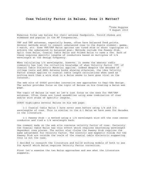
<strong>Coax</strong> <strong>Velocity</strong> <strong>Factor</strong> <strong>in</strong> <strong>Baluns</strong>, Does it Matter?<br />
©John <strong>Hugg<strong>in</strong>s</strong><br />
9 August 2010<br />
Numerous folks use baluns for their antenna feedpo<strong>in</strong>ts. Toroid chokes are<br />
wideband and popular <strong>in</strong> the HF frequencies.<br />
VHF and UHF antennas, especially beams, often have balanced feed po<strong>in</strong>ts.<br />
Several methods exist to connect unbalanced coax to the dipole element: gamma,<br />
t-match, etc. Some VHF/UHF Balun options use tuned stub or shunt topologies to<br />
achieve the unbalanced to balanced goal; Methods <strong>in</strong>clude the Pawsey Stub,<br />
Split <strong>Coax</strong> Balun, <strong>Coax</strong>ial Cable Balun and Folded Balun to name a few. Each of<br />
these requires specific lengths of conductors based on multiples of 1/4<br />
wavelength at the design frequency.<br />
When calculat<strong>in</strong>g 1/4 wavelengths, however, it seems the amateur radio<br />
community has lost the collective knowledge of when <strong>Velocity</strong> <strong>Factor</strong> (VF) of<br />
<strong>Coax</strong>ial Cable Dielectric Material applies. Indeed despite the decades of<br />
college texts and ARRL Antenna books show<strong>in</strong>g otherwise, the idea <strong>Velocity</strong><br />
<strong>Factor</strong> always applies to coaxial cable length calculations when used as<br />
noth<strong>in</strong>g more than a wire stub <strong>in</strong> a Balun seems to have gone viral on the<br />
Internet.<br />
The web site of G0KSC provides <strong>in</strong>novative new approaches to Yagi-Uda design.<br />
The author provides focus on the topic of <strong>Baluns</strong> on his Creat<strong>in</strong>g a Balun web<br />
page.<br />
The topic of <strong>Baluns</strong> is vast so let’s just focus on the ones for VHF/UHF<br />
antennas. Often these are tuned assemblies us<strong>in</strong>g some comb<strong>in</strong>ation of coax<br />
and/or wire stubs of specific lengths.<br />
G0KSC highlights several <strong>Baluns</strong> on his web page:<br />
1:1 <strong>Coax</strong>ial Cable Balun I have never seen before us<strong>in</strong>g 1/4 and 3/4<br />
wavelengths of coax. This is similar to the 4:1 Balun we have seen for decades<br />
<strong>in</strong> the literature.<br />
1:1 Pawsey Stub – a method us<strong>in</strong>g a 1/4 wavelength wire off the coax center<br />
conductor and tied a 1/4 wavelength back.<br />
One comment made on the web site concerns velocity factor of coax. Certa<strong>in</strong>ly<br />
the <strong>Coax</strong>ial Cable Balun has this effect which requires shorten<strong>in</strong>g wavelength<br />
dependent coax pieces. The author also claims the Pawsey Stub requires the<br />
same adjustment for velocity factor. The electric and magnetic fields for the<br />
Pawsey Stub are outside the realm of the coaxial cable dielectric suggest<strong>in</strong>g<br />
this is not the case.<br />
I decided to research the literature and build work<strong>in</strong>g models of both to see<br />
for myself which Balun requires <strong>Velocity</strong> <strong>Factor</strong> correction.<br />
First let’s exam<strong>in</strong>e the two Balun approaches and see what the literature<br />
suggests.
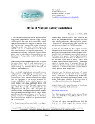
1:1 <strong>Coax</strong>ial Cable Balun<br />
Figure 1 shows the pieces of this<br />
Balun…<br />
This topology is brilliantly simple. A<br />
description can be found at I0QM’s web<br />
site PDF file[1].<br />
Fig 1 - 1:1 RF Balun us<strong>in</strong>g 1/4 and<br />
3/4 wave coaxial cables<br />
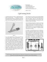
Folded Balun (aka Pawsey Stub) and<br />
1/4 Wave <strong>Coax</strong>ial Balun<br />
Figure 2 shows the idea beh<strong>in</strong>d the<br />
Pawsey stub which is known <strong>in</strong><br />
Electrical Eng<strong>in</strong>eer<strong>in</strong>g circles as a<br />
variant of the Folded Balun[2].<br />
While the Gray conductor <strong>in</strong> Figure 2<br />
only needs to be a wire of similar<br />
size to the coaxial cable feedl<strong>in</strong>e,<br />
it is often made from a scrap piece<br />
of the same cable. Each end of the<br />
outer shield of the stub is connected<br />
to the feed system. A common thought<br />
of many is s<strong>in</strong>ce this is coaxial<br />
cable, we need velocity factor<br />
adjustments. S<strong>in</strong>ce the electric and<br />
magnetic fields (of the stub system)<br />
are <strong>in</strong> air, I th<strong>in</strong>k velocity factor<br />
does not apply.<br />
Fig 2 - Folded Balun (aka Pawsey<br />
Stub)
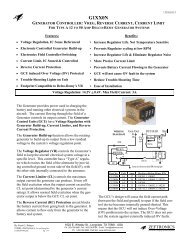
Figure 3 highlights my<br />
reason<strong>in</strong>g…<br />
Fig 3 - Electric and<br />
Magnetic fields <strong>in</strong><br />
dielectric materials<br />
def<strong>in</strong>e when velocity<br />
factor applies.<br />
Fig 3 - Electric and<br />
Magnetic fields <strong>in</strong><br />
dielectric materials<br />
def<strong>in</strong>e when velocity<br />
factor applies.<br />
Figure 3a shows the<br />
construction of coaxial<br />
cable we are all<br />
familiar with. In<br />
normal operation all<br />
electric and most of<br />
the magnetic fields are<br />
conta<strong>in</strong>ed between the<br />
<strong>in</strong>ner and outer<br />
conductors. S<strong>in</strong>ce the<br />
spac<strong>in</strong>g between these<br />
conductors is<br />
ma<strong>in</strong>ta<strong>in</strong>ed by an<br />
<strong>in</strong>sulat<strong>in</strong>g material,<br />
the fields are<br />
completely dependent on<br />
the dielectric constant<br />
of this material.<br />
Fig 3 - Electric and Magnetic fields <strong>in</strong> dielectric<br />
materials def<strong>in</strong>e when velocity factor applies.<br />
Figure 3b shows the same coaxial cable, but this time there are two pieces<br />
side by side as used <strong>in</strong> the Folded Balun. This balun, essentially a parallel<br />
transmission l<strong>in</strong>e, develops all its fields between the outer sk<strong>in</strong> of the<br />
cables’ shields, not with<strong>in</strong>. The stub wire, as used <strong>in</strong> the Pawsey Stub method,<br />
could be a copper wire with the same effect.<br />
The studious reader will notice the external fields are not entirely <strong>in</strong> free<br />
air. The cable jacket certa<strong>in</strong>ly has a dielectric constant greater than 1 and,<br />
as th<strong>in</strong> as it is, will retard the speed of light a bit. The effect is much<br />
less than the situation <strong>in</strong>side coax, however. So… the VF of free air is not<br />
quite 1, but almost is… about 0.90 to 0.98 or so.<br />
UPDATE Oct 2010:<br />
Measurements made on a variety of Folded Balun test samples reveal the<br />
<strong>Velocity</strong> <strong>Factor</strong> actually varies from 0.7 to over 1 depend<strong>in</strong>g on cable type and<br />
spac<strong>in</strong>g. None matched the <strong>Velocity</strong> <strong>Factor</strong> caused by the dielectric <strong>in</strong>side the<br />
coax. The spac<strong>in</strong>g between the two conductors had an enormous impact on the<br />
f<strong>in</strong>al tun<strong>in</strong>g po<strong>in</strong>t. The range of values was a surprise to this author. Details<br />
on these tests will be available <strong>in</strong> an upcom<strong>in</strong>g post.<br />
Other Views<br />
Balanis discusses the theory beh<strong>in</strong>d match<strong>in</strong>g techniques <strong>in</strong>clud<strong>in</strong>g the 1/4 Wave<br />
<strong>Coax</strong>ial 1:1 Balun. In particular he describes the purpose of the electrical<br />
short of the coax center conductor to shield, is to ma<strong>in</strong>ta<strong>in</strong> balance, thereby,
ensur<strong>in</strong>g no current flows back to the transceiver on the outside of the coax.<br />
Interest<strong>in</strong>gly, he notes…<br />
“The parallel auxiliary l<strong>in</strong>e need not be made 1/4 wave <strong>in</strong> length to<br />
achieve the balance. It is made 1/4 wave to prevent the upsett<strong>in</strong>g of the<br />
normal operation of the antenna.”[3]<br />
The above po<strong>in</strong>t suggests a stub with <strong>in</strong>correctly calculated lengths<br />
effectively quells unbalanced feedl<strong>in</strong>e currents (good) while corrupt<strong>in</strong>g the<br />
balance <strong>in</strong> the antenna (bad). It appears easy to be lured <strong>in</strong>to a false sense<br />
of security.<br />
The Pawsey Stub approach is noth<strong>in</strong>g new. For decades the Stub Balun has been<br />
described <strong>in</strong> the various editions of the ARRL Antenna Book. The 21st edition<br />
describes a Sleeve Balun and the Stub Balun and suggests each is to be 1/4<br />
wavelength. It does not mention anyth<strong>in</strong>g about velocity factor corrections<br />
leav<strong>in</strong>g the reader to wonder.[4]<br />
Go back <strong>in</strong> time and we f<strong>in</strong>d the 13th edition of the ARRL Antenna Book says<br />
this about the stub approach…<br />
“In either case, the length of the detun<strong>in</strong>g element is a full quarter<br />
wavelength; the propagation factor of the l<strong>in</strong>e does not enter <strong>in</strong>to the<br />
picture here.”[5]<br />
Yet another view is noted by Roberts while describ<strong>in</strong>g his Wide-Band Balun<br />
named for him[6] stat<strong>in</strong>g about how long to make the parallel sections of coax<br />
thus…<br />
“The length of the parallel section, measured from the po<strong>in</strong>t [. . .]<br />
where the two braids are connected together, to the po<strong>in</strong>ts [. . .] where<br />
the balanced circuit is to be connected, is made one-quarter wavelength<br />
at the center frequency of the operat<strong>in</strong>g range. For the determ<strong>in</strong>ation of<br />
this length, it is necessary to take account of the propagation<br />
velocity, which is somewhat higher than that of the waves mov<strong>in</strong>g along<br />
the <strong>in</strong>side of the coaxial cables.”[6]<br />
Roberts recognized the fields of the parallel portion of his design are <strong>in</strong> a<br />
mix of free air and sheath dielectric. He goes on…<br />
“Because of variations <strong>in</strong> composition, diameter, or eccentricity of the<br />
outer <strong>in</strong>sulation, the characteristics of parallel l<strong>in</strong>es formed from<br />
certa<strong>in</strong> coaxial cable samples may differ appreciably from the desired<br />
value. It is generally necessary, therefore, to determ<strong>in</strong>e the<br />
characteristic impedance and velocity of propagation by test<strong>in</strong>g sample<br />
parallel l<strong>in</strong>e sections made of the <strong>in</strong>tended material.”[6]<br />
Heed<strong>in</strong>g Roberts’ warn<strong>in</strong>g and evaluat<strong>in</strong>g the other evidence above, I assert the<br />
published values of velocity factor of coaxial cable should not be used for<br />
stub length calculations for stubs with fields outside the cable’s <strong>in</strong>terior.<br />
Am I right? Let’s quit guess<strong>in</strong>g and test it!<br />
Part 2 of this series highlights the actual test I performed to prove I am<br />
correct.
<strong>Coax</strong> <strong>Velocity</strong> <strong>Factor</strong> <strong>in</strong> <strong>Baluns</strong>, Does it Matter? Part 2<br />
In the previous post I discuss various attributes concern<strong>in</strong>g the use of <strong>Baluns</strong><br />
especially <strong>in</strong> the VHF/UHF bands. I po<strong>in</strong>t out other web sites with excellent<br />
tutorials on why and where to use <strong>Baluns</strong> <strong>in</strong> VHF work. Two particular Balun<br />
styles come up strong: 1:1 <strong>Coax</strong>ial Cable Balun and the Pawsey Stub otherwise<br />
known as 1:1 Folded Balun. Each Balun’s topologies are shown <strong>in</strong> Figures 1 and<br />
2. I highlight the mistaken, I believe, assertion one should adjust the Pawsey<br />
Stub’s length by the amount of the coaxial cable velocity factor. Figure 3<br />
shows why I th<strong>in</strong>k the Pawsey Stub length does not need as drastic a reduction<br />
<strong>in</strong> length as you might do for stubs that conta<strong>in</strong> the electric and magnetic<br />
fields with<strong>in</strong> their structure. F<strong>in</strong>ally, I say I will prove my assertion the<br />
Pawsey Stub is electrically a 1/4 wave <strong>in</strong> free space or close.<br />
What follows is the experiment which provides proof <strong>Velocity</strong> <strong>Factor</strong> of <strong>Coax</strong>ial<br />
Cables does not apply to cables used simply as a wire <strong>in</strong> parallel with another<br />
wire.<br />
The Experiment<br />
The two <strong>Baluns</strong> are an excellent pair to compare. The <strong>Coax</strong>ial Cable Balun is<br />
just two transmission l<strong>in</strong>es tied together one 1/4 wavelength long, the other<br />
3/4 wavelength long. In this case the electric and magnetic fields are<br />
entirely with<strong>in</strong> the dielectric material. Thus the velocity factor adjustment<br />
should apply. The Pawsey Stub relies entirely on becom<strong>in</strong>g a parallel<br />
transmission l<strong>in</strong>e with the feedl<strong>in</strong>e coax. Its fields are entirely outside the<br />
structure of the coax.<br />
Fig 4 - <strong>Coax</strong>ial Cable Balun with 1/4 and 3/4<br />
sections of coax, cut for 300MHz Freespace, <strong>in</strong><br />
parallel.<br />
I built the two baluns<br />
us<strong>in</strong>g some RG316 coax.<br />
My target frequency for<br />
both is 300 MHz. I cut<br />
pieces with no<br />
corrections applied to<br />
see how the frequency<br />
changes.<br />
The <strong>Coax</strong>ial Cable Balun<br />
has the follow<strong>in</strong>g<br />
dimensions based on<br />
calculations…<br />
! 1/4 wave section =<br />
300m/s / 300 MHz * .25 =<br />
25cm ~ 9.8 <strong>in</strong>ches<br />
! 3/4 wave section =<br />
300m/s / 300 MHz * .75 =<br />
75cm ~ 29.5 <strong>in</strong>ches<br />
I simply cut two pieces<br />
of coax to the above<br />
lengths and added a<br />
third with an SMA<br />
connector for the feed<br />
l<strong>in</strong>e.<br />
Figure 4 shows the
<strong>Coax</strong>ial Cable Balun with<br />
a 50 ohm resistance at<br />
the balanced feed po<strong>in</strong>t.<br />
With the resistance at<br />
the feedpo<strong>in</strong>t, the Balun<br />
should show some very<br />
obvious frequency<br />
dependence on a Return<br />
Loss or SWR plot.<br />
Because this is the case<br />
where <strong>Velocity</strong> factor<br />
does apply, the target<br />
frequency of 300 MHz<br />
should be lowered by<br />
.695 or about 208 MHz.<br />
Given that I flayed the<br />
coax shield and center,<br />
thereby reduc<strong>in</strong>g some of<br />
the coaxial cable<br />
length, the actual<br />
frequency should be a<br />
little higher.<br />
Figure 5 shows what<br />
happens when I connect<br />
the <strong>Coax</strong>ial Cable Balun<br />
to the VNA…<br />
Fig 5 - Return Loss of <strong>Coax</strong>ial Cable Balun from 100<br />
- 500 MHz. Markers M1 and M2 are at 300 and 214 MHz<br />
respectively.<br />
Wow! The 214 MHz pretty<br />
much confirms that<br />
<strong>Velocity</strong> <strong>Factor</strong> is well<br />
<strong>in</strong> play for this style<br />
of Balun.<br />
Now let’s try the Pawsey Stub. The<br />
only critical dimension is the stub<br />
length.<br />
1/4 wave section = 300m/s / 300<br />
MHz * .25 = 25cm ~ 9.8 <strong>in</strong>ches<br />
Once aga<strong>in</strong>, my trimm<strong>in</strong>g slightly<br />
shortens the actual electrical length<br />
to about 9.2 <strong>in</strong>ches which raises the<br />
frequency just a bit. Figure 6 shows<br />
my test unit with 50 ohms at the feed<br />
po<strong>in</strong>t.<br />
What’s the prediction here? If you<br />
listen to the web sites which suggest<br />
coax cable VF applies, the frequency<br />
will be between 210 and 230 MHz. If I<br />
am right and this is free space, or<br />
very close to free space, then the<br />
frequency should be about 300 MHz, or<br />
s<strong>in</strong>ce the connection po<strong>in</strong>ts on the<br />
stub are a little closer together,<br />
someth<strong>in</strong>g a bit higher. Let’s see the<br />
Return Loss plot…<br />
Fig 6 - Pawsey Stub Balun with 1/4<br />
of coax, cut for 300MHz Freespace,<br />
<strong>in</strong> alongside the feedl<strong>in</strong>e.
Fig 7 - Return Loss of Folded Balun from<br />
100 - 500 MHz. Markers M1 and M2 are at 300<br />
and 322 MHz respectively.<br />
Bulls Eye!!!!<br />
This strongly suggests the<br />
lengths of external stubs, like<br />
the Pawsey Stub (or any Folded<br />
Balun variant), should be<br />
calculated us<strong>in</strong>g free space<br />
wavelengths without corrections<br />
for <strong>Velocity</strong> <strong>Factor</strong>.<br />
The funny th<strong>in</strong>g is, this has<br />
been the case <strong>in</strong> the ARRL<br />
Antenna book for many many<br />
years. The later editions never<br />
suggest to apply velocity factor<br />
to external stub calculations<br />
and the 13th edition<br />
specifically says VF does not<br />
apply.<br />
Interference from Nearby Objects<br />
– an Additional Observation<br />
Test<strong>in</strong>g of the above two <strong>Baluns</strong><br />
revealed an <strong>in</strong>terest<strong>in</strong>g<br />
behavior. The 1:1 <strong>Coax</strong>ial Cable<br />
Balun was immune to effects from<br />
handl<strong>in</strong>g dur<strong>in</strong>g the test. The<br />
Pawsey Stub was very sensitive<br />
to touch or even be<strong>in</strong>g close to<br />
the stub portion. This evidence correlates well with the measurements<br />
suggest<strong>in</strong>g the Pawsey Stub’s electric and magnetic fields are, at least some<br />
if not entirely, outside the realm of any dielectric material.<br />
Conclusion<br />
It is a good th<strong>in</strong>g Amateur Radio Operators know about transmission l<strong>in</strong>e<br />
<strong>Velocity</strong> <strong>Factor</strong> specifications. Without this knowledge you would be cutt<strong>in</strong>g<br />
stubs <strong>in</strong>correctly. However, some Amateurs assume that just because a piece of<br />
coax is used for a stub, <strong>Velocity</strong> <strong>Factor</strong> applies. The key to understand<strong>in</strong>g<br />
when it does and when it doesn’t is found by follow<strong>in</strong>g the electric and<br />
magnetic fields. Where are they? Are they <strong>in</strong>side the coax or outside between<br />
pieces of coax? If <strong>in</strong>side, apply VF. If outside assume freespace.<br />
Measure, but verify…<br />
This experiment relies on some crude cutt<strong>in</strong>g of cable lengths and assumed<br />
values of <strong>Velocity</strong> <strong>Factor</strong>. Potential sources of error <strong>in</strong>clude:<br />
! Cable End Trimm<strong>in</strong>g – Source for my slight errors above<br />
! <strong>Coax</strong> <strong>Velocity</strong> <strong>Factor</strong> not what the manufacturer says – When you do need<br />
to know VF, it might be a bit off especially with lower quality coax<br />
! Freespace not quite freespace – Even the best air gap transmission l<strong>in</strong>e<br />
has some dielectric material <strong>in</strong> the fields – VF values of 0.95 are common even<br />
with parallel transmission ladder l<strong>in</strong>e.<br />
So what does this suggest? If you are go<strong>in</strong>g to the trouble to make someth<strong>in</strong>g<br />
as critical as a Balun for your Yagi antenna, electrically measure each cable<br />
with your SWR meter or VNA to ensure you are spot on the frequency of choice.
This was an <strong>in</strong>terest<strong>in</strong>g test. I am now so <strong>in</strong>terested <strong>in</strong> <strong>Baluns</strong>, I will focus<br />
on posts for each type <strong>in</strong> the near future.<br />
Thanks for read<strong>in</strong>g.<br />
John<br />
References:<br />
I0QM. “<strong>Coax</strong>ial Balun by I0QM.”<br />
http://www.iw5edi.com/ham-radio/files/I0QM_BALUN.PDF, 2001.<br />
Milligan, Thomas. Modern Antenna Design. McGraw-Hill, Inc., 1985, pp.<br />
74-77.<br />
Balanis, Constant<strong>in</strong>e. Antenna Theory – Analysis and Design. John Wiley &<br />
Sons, Inc., 1982, pp. 365-368.<br />
R. Dean Straw et al. “<strong>Baluns</strong> and Antenna Tuners.” ARRL Antenna Book. The<br />
ARRL, Inc. 21st ed. 2007. pp 18.6-18.7.<br />
Gerald L. Hall et al. “Us<strong>in</strong>g <strong>Coax</strong>ial L<strong>in</strong>es” ARRL Antenna Book. The<br />
American Radio Relay League, Inc. 13th ed. 1974. pp 229-230.<br />
Proceed<strong>in</strong>gs of the IRE, “A New Wide-Band Balun,” Proceed<strong>in</strong>gs of the IRE,<br />
Volume 45, Issue 12, December 1957, pp 1628-1631<br />
This f<strong>in</strong>e article was posted to a website at http://t<strong>in</strong>yurl.com/7out6f9<br />
I have captured it and reformatted to a s<strong>in</strong>gle .pdf file here for the<br />
edification of <strong>AeroElectric</strong> <strong>Connection</strong> readers. My s<strong>in</strong>cere thanks to John<br />
<strong>Hugg<strong>in</strong>s</strong> for shar<strong>in</strong>g his scholarly effort and <strong>in</strong>sight on this topic with the<br />
world community. John’s attitude for “let’s go to the bench and test it” is <strong>in</strong><br />
keep<strong>in</strong>g with the f<strong>in</strong>est traditions for explor<strong>in</strong>g, identify<strong>in</strong>g and teach<strong>in</strong>g of<br />
simple-ideas. BN
![G-Series-Ext [pdf] - Carling Technologies](https://img.yumpu.com/50918301/1/190x245/g-series-ext-pdf-carling-technologies.jpg?quality=85)