ASSEMBLY INSTRUCTIONS - Carl's Electronic Kits
ASSEMBLY INSTRUCTIONS - Carl's Electronic Kits
ASSEMBLY INSTRUCTIONS - Carl's Electronic Kits

You also want an ePaper? Increase the reach of your titles
YUMPU automatically turns print PDFs into web optimized ePapers that Google loves.
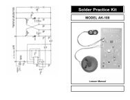
AK-870<br />
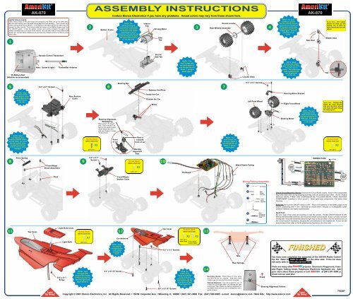
<strong>ASSEMBLY</strong> <strong>INSTRUCTIONS</strong><br />
Contact Elenco <strong>Electronic</strong>s if you have any problems. Actual colors may vary from those shown here.<br />
AK-870<br />
INSPECTION OF PARTS<br />
Take a look at each of the parts bags and compare to the Parts List (on the other side).<br />
Be sure that nothing was damaged during shipment and handling. There should be 8<br />
wires coming off the Circuit Board - 2 connecting to the light bulb, and 6 others that will<br />
connect to other circuits. There should also be 3 wires on the Bottom Frame (one from<br />
the ON/OFF switch, 1 from the battery section, and another between the switch and<br />
battery contacts) and 2 on each of the motors. Be sure that none of these wires have<br />
broken off. Contact Elenco <strong>Electronic</strong>s if you have any problems (phone number is on the<br />
other side).<br />
Bottom Frame<br />
NOTE: The<br />
Interior Tab should<br />
not touch the metal shell<br />
of the motor. It should fit<br />
into the slot of the middle<br />
compartment, bend if<br />
necessary. The side tab may<br />
either be bent to lay along<br />
the motor shell or point<br />
out the right side.<br />
Interior<br />
Tab<br />
Driving Motor<br />
Side<br />
Tab<br />
Round Locator<br />
Rear Wheels Assembly<br />
NOTE: Put some<br />
Vaseline or grease<br />
into the slots for the rod<br />
and some on the teeth of<br />
all the gears (motor gear,<br />
middle gear, and the rear<br />
wheels gear). This will<br />
make the car go<br />
faster.<br />
Rear Rod<br />
Quick Test: All 3 gears<br />
should be lined up and<br />
turning one of them by<br />
hand should also turn the<br />
others.<br />
Middle Gear<br />
Remote Control Transmitter<br />
Slot for<br />
Side Tab<br />
9V Battery Slot<br />
(Alkaline recommended)<br />
Note: Screw in tight.<br />
Transmitter Antenna<br />
NOTE: The<br />
next 3 steps will<br />
be much easier if<br />
you elevate the car<br />
about 1” using a<br />
small object.<br />
Locator Slots<br />
NOTE: Make<br />
sure that the middle<br />
gear is to the left of the<br />
tab in the case as<br />
shown. The middle gear<br />
must lie between the<br />
rear wheels gear<br />
and the tab.<br />
Tab<br />
Steering Bar<br />
0.3” x 0.1” Screws<br />
0.4” x 0.1” Screws<br />
Between the Wires<br />
NOTE: Align<br />
the front of the<br />
Rear Section Cover<br />
before aligning the<br />
screw holes in<br />
the rear.<br />
Rear Section<br />
Cover<br />
Steering Alignment<br />
Wire/Spring<br />
Bend wires to fit around<br />
post. They must NOT be<br />
tight (or the steering won’t<br />
work), stretch the wire<br />
with your fingers to loosen<br />
it if necessary.<br />
Inside the Car<br />
Outside the Car<br />
Wires<br />
Left Front Wheel<br />
Steering Motor Bracket<br />
Right Front Wheel<br />
Steering Motor<br />
NOTE: The gear<br />
should lay on the<br />
teeth of the steering<br />
bar (get assistance if it<br />
does not). Add some<br />
Vaseline or grease<br />
to the teeth.<br />
Quick Test: Turning one<br />
wheel by hand should<br />
also turn the other wheel<br />
and move the gear along<br />
the steering bar.<br />
NOTE: Make<br />
sure that the wires<br />
from the ON/OFF switch<br />
and the motor run out of<br />
the rear section cover<br />
through the slots (as<br />
shown) without being<br />
damaged.<br />
Screw Used<br />
(shown actual size)<br />
0.4” x 0.1”<br />
X2<br />
Front<br />
of car<br />
Post is<br />
towards<br />
front of car<br />
Steering<br />
Alignment<br />
Post<br />
NOTE: The<br />
next 3 steps will<br />
be much easier if<br />
you elevate the car<br />
about 1” using a<br />
small object.<br />
Screw Used<br />
(shown actual size)<br />
0.3” x 0.1”<br />
X2<br />
Front Spring<br />
Front Wheel<br />
Shock Absorbers<br />
0.3” x 0.1”<br />
Screws<br />
Screw Used<br />
(shown actual size)<br />
X2<br />
Black Plastic Tubing<br />
YELLOW<br />
Driving<br />
Motor<br />
YELLOW<br />
WIRING PLAN<br />
ANTENNA<br />
0.3” x 0.1”<br />
PC Board<br />
GREEN<br />
GREEN<br />
BLUE<br />
BLUE<br />
Post<br />
Front Wheels<br />
Section Cover<br />
Wiring/Tubing Assembly<br />
RED<br />
RED<br />
ORANGE<br />
Steering<br />
Motor<br />
ORANGE<br />
1 Cut Tubing<br />
BLACK<br />
BLACK<br />
2<br />
3<br />
Tubing<br />
Tubing<br />
Slide<br />
Tubing<br />
onto wire.<br />
Twist<br />
wires<br />
together.<br />
Check Circuit Board for Shorts: Examine the Circuit Board closely. Some of the components<br />
may have been bent during shipping and may now be touching each other. IN NO CASES<br />
SHOULD METAL FROM ONE COMPONENT BE TOUCHING METAL FROM ANOTHER<br />
COMPONENT (creating a “short circuit”). Bend apart any components that have metal<br />
touching.<br />
Batteries: Be sure the ON/OFF switch is OFF. Place 4 AA batteries in the battery cage on the<br />
bottom, positioning their + and - terminals as shown there. Alkaline or rechargeable nickelcadmium<br />
batteries are highly recommended.<br />
4<br />
5<br />
Slide<br />
Tubing over<br />
the twisted<br />
wires.<br />
Quick Test:<br />
Be sure none of the wires are touching or near the wheels. Flip the ON/OFF Switch to ON,<br />
extend the Transmitter Antenna, and move the remote control levers. If your car does not work<br />
initially then move the transmitter antenna right next to the car (touch it to the antenna wire on<br />
the Circuit board if necessary), because the car’s antenna is not installed yet. If your car still<br />
does not work then refer to the Troubleshooting Section on the other side.<br />
Top Cover<br />
Light Bulb Cover<br />
0.4” x 0.1”<br />
Screw<br />
Light Bulb<br />
Screw Used<br />
(shown actual size)<br />
0.4” x 0.1”<br />
X1<br />
NOTE: Tape<br />
the light bulb<br />
wires to the inside<br />
of the top cover so<br />
that the light bulb<br />
stays above it.<br />
0.4” x 0.115” Screw<br />
Car Antenna<br />
NOTE: Insert<br />
the antenna<br />
through the top<br />
cover before<br />
screwing it<br />
down.<br />
Top Cover<br />
0.3” x 0.1” Screws<br />
0.4” x 0.115” Screws<br />
Screws Used<br />
(shown actual size)<br />
NOTE: Be<br />
careful not to<br />
stress or break any<br />
of the wires and<br />
connections. You may<br />
also want to tape the<br />
wires down to keep<br />
them inside the<br />
car.<br />
Copyright © 2001 Elenco <strong>Electronic</strong>s, Inc. All Rights Reserved. • 150 W. Carpenter Ave. • Wheeling, IL 60090 • (847) 541-3800 Fax: (847) 520-0085 • e-mail: elenco@elenco.com • Web Site: http://www.elenco.com<br />
0.3” x 0.1”<br />
(4mm head)<br />
X2<br />
X3<br />
0.4” x 0.115”<br />
(5.3mm head)<br />
Tabs<br />
Rear Springs<br />
Decorative Decals: Place these on now, using<br />
your AK-870 box as a guide. Note that some<br />
models may not use all of the stickers provided.<br />
Steering Alignment: Your car is ready for use. If<br />
it does not go straight when you release the right<br />
control lever, then adjust the steering alignment on<br />
the bottom front of the car with a screwdriver until it<br />
works properly.<br />
é<br />
Front<br />
You have now completed the assembly of the AK-870 Radio Control<br />
Car Kit. Refer to HOW TO USE IT on the other side. If the car does<br />
not work, refer to TROUBLESHOOTING .<br />
There are many other projects: <strong>Electronic</strong> Playground, Cassette<br />
Player, Talking Clock, Telephone, <strong>Electronic</strong> Keyboard, etc. Ask<br />
your store about these projects or call<br />
at (847) 541-3800 or<br />
check out our web site!<br />
Steering Alignment Control<br />
753287
RADIO-CONTROLLED<br />
CAR KIT<br />
AK-870<br />
Manufactured by<br />
Elenco <strong>Electronic</strong>s, Inc.<br />
150 W. Carpenter Avenue<br />
Wheeling, IL 60090<br />
Copyright © 2001 Elenco <strong>Electronic</strong>s, Inc.<br />
753287-E<br />
WHAT IT IS<br />
The AK-870 is a radio-controlled car that you put together. It has 7 control<br />
functions: forward, forward-left, forward-right, backward, backward-left,<br />
backward-right, and stop. The remote control operates at a frequency of<br />
27.9 MHz. It uses 4 AA batteries and one 9V battery (not included). The<br />
car is mechanically assembled by the user with no soldering required.<br />
In addition to the experience of building the unit, there is also an overview<br />
of its operation, a block diagram, an electronic road map showing the<br />
electrical circuits, and a troubleshooting section in case of problems.<br />
Recommended for ages 12 and up. It takes about 3 hours to build.<br />
YOU WILL NEED:<br />
r Screwdriver (Phillips type, small-medium size)<br />
r Vaseline or grease<br />
r tape (Scotch type will be fine)<br />
r scissors<br />
r 1 9V battery (alkaline is recommended)<br />
r 4 AA batteries (alkaline or rechargeable nickel-cadmium are highly<br />
recommended). Do not mix old and new, and different types of<br />
batteries.<br />
r You may also need a standard screwdriver in step 14.<br />
!<br />
WARNING:<br />
CHOKING HAZARD - Small Parts.<br />
Not for children under 5 years.<br />
! WARNING: !<br />
Contains a GLASS BULB which could<br />
cause an injury if the toy is broken.<br />
2<br />
!<br />
HOW TO USE IT<br />
Place the car in a flat, open area, turn the ON/OFF switches on the car<br />
and the transmitter to ON, and extend the antenna on the Remote Control.<br />
The LEFT lever on the Remote Control:<br />
Push forward (or forward-right) to make the AK-870 go forward.<br />
Push backward to make the AK-870 go backward.<br />
Push to center or let go to stop.<br />
The RIGHT lever on the Remote Control:<br />
Push left to make the AK-870 turn left.<br />
Push right to make the AK-870 turn right.<br />
Push to center or let go to go straight.<br />
Turbo King operates best on a wood or tile floor or in your driveway.<br />
Never operate Turbo King in the street.<br />
These suggestions will help make your car last for years of fun:<br />
• Never drive your car in rain, snow, mud, sand, dirt, or on a wet floor,<br />
as damage may result.<br />
• Do not drive your car on carpet since lint may damage the wheel<br />
mechanism.<br />
THE FCC<br />
The Federal Communications Commission (FCC) regulates use of the<br />
radio frequency spectrum in the United States to prevent products from<br />
interfering with each other.<br />
FCC regulations for your the AK-870 require you to accept any<br />
interference from authorized sources and that you shut down if you are<br />
causing interference with other authorized products. Contact Elenco<br />
<strong>Electronic</strong>s if you need assistance.<br />
You should never modify the electrical circuit components inside your car<br />
or Remote Control transmitter as this may cause malfunctions or violate<br />
FCC regulations for this product.<br />
3<br />
PARTS LIST<br />
Contact Elenco <strong>Electronic</strong>s if parts are missing or damaged. DO NOT<br />
contact your place of purchase as they will not be able to help you.<br />
You may have been given different screws from<br />
QTY DESCRIPTION<br />
BAG 1<br />
those specified here (and usually some spares).<br />
Contact Elenco if it is not clear which to use.<br />
PART #<br />
(6AK870B1E)<br />
r 3 Screws 0.4” x 0.1” (10mm x 2.6mm) 640101<br />
r 3 Screws 0.4” x 0.115” (10mm x 3.0mm) 640101E<br />
r 5 Screws 0.3” x 0.1” (8mm x 2.6mm), 0.15” head 640102<br />
r 1 Screws 0.3” x 0.1” (8mm x 2.6mm),0 .2” head<br />
BAG 2<br />
640102E<br />
(6AK870B2E)<br />
r 2 Rear Springs 680023<br />
r 1 Front Spring 680024<br />
r 2 Front Wheel Shock Absorber (small spring) 680025<br />
r 1 Middle Gear 610809<br />
r 1 Rear Rod 0.8” x 0.075” (20mm x 2mm) 610808<br />
r 1 Steering Alignment Wire/Spring 6RCC7K11<br />
r 1 Steering Alignment Post 6RCC7K36E<br />
r 1 Steering Motor Bracket<br />
BAG 3<br />
626018E2<br />
(6AK870B3E)<br />
r 1 Left Front Wheel 662018E1<br />
r 1 Right Front Wheel 662018E2<br />
r 1 Front Section Cover 626018E1<br />
r 1 Rear Section Cover 626019E<br />
r 1 Light Bulb Cover 626022<br />
r 1 Steering Bar 626023E<br />
r 1 Transmitter Antenna 484010E<br />
BAG 4<br />
r 1 Bottom Frame 610910E<br />
r 1 Car Antenna 484011E<br />
BAG 5<br />
r 1 Driving Motor 6AK870B5E<br />
BAG 6<br />
r 1 Steering Motor 6AK870B6E<br />
BAG 7<br />
r 1 Circuit Board 6AK870B7E<br />
PACKAGED SEPARATELY<br />
r 1 Remote Control Transmitter 6AK870TAE<br />
r 1 Top Cover 6AK870TFE<br />
r 1 Rear Wheels Assembly 6AK870RWAE<br />
r 1 Decorative Decals (1 Sheet) 720063E<br />
r 1 Plastic Tubing (at least 6”)<br />
4<br />
890014<br />
Remote Control Transmitter:<br />
When the levers in the Remote Control Unit are pushed electrical contacts<br />
are made connecting the 9V battery power to the transmitter and<br />
indicating which commands the user wants sent to the car.<br />
Forwards/Backwards and Left/Right commands are controlled by different<br />
levers and use different sets of electrical contacts that are used to encode<br />
a sequence of electrical pulses; the number of pulses depends on which<br />
command is being sent. In some models Left/Right commands are only<br />
sent if Forwards/Backwards commands are also being sent, since there is<br />
too much friction to turn the wheels unless the car is moving. An electrical<br />
circuit that is tuned to a frequency of 27.9 MHz creates a signal that is sent<br />
to the antenna when the pulses are active. The antenna converts this<br />
electrical energy into radio energy, creating a stream of radio energy<br />
bursts, which travel through the air and are picked up by and understood<br />
by the radio receiver in the car. The frequency of 27.9 MHz was selected<br />
for your AK-870 with the approval of the FCC (the US government) to<br />
minimize radio interference between this product and all other electrical<br />
products.<br />
Radio Receiver:<br />
The car antenna collects radio energy and converts it back into electrical<br />
energy; the energy here will always be much less than the energy<br />
originally applied to the transmitting antenna. If the car is turned on then<br />
the radio receiver in the car is continuously monitoring the electrical<br />
energy from its antenna. The receiver is basically a filter which is tuned to<br />
amplify any energy around 27.9 MHz and block energy the antenna picks<br />
up outside this region. If the Remote Control Transmitter is sending<br />
commands then its radio signal will be picked up by the receiver and<br />
converted back into the original pulse sequence. Decoding circuitry then<br />
determines which commands were sent by measuring the number of<br />
received pulses in the sequence. Signals are then sent to the motors to<br />
execute the commands.<br />
Characteristics of Radio Reception:<br />
Many factors affect the ability of the AK-870 to receive commands from its<br />
Remote Control Transmitter. A weak battery in the Transmitter will result<br />
in a weaker transmitted signal; if the battery is very weak then the<br />
Transmitter may not function at all. The Transmitter’s ability to convert<br />
electrical energy to radio energy is best when its antenna is fully extended<br />
and degrades as the antenna length is reduced; the same thing also<br />
HOW IT WORKS<br />
applies to the car antenna’s ability to convert the radio signal back into<br />
electrical energy for the receiver. The Transmitter’s antenna transmits<br />
energy in all directions so as the range between it and the car is increased<br />
less energy is received at the car. When operated with strong batteries<br />
and in an open area the range will be at least 40 ft. Obstacles such as<br />
walls, furniture, and trees will degrade the radio signal’s ability to travel<br />
through air and reduce operating range, but will never block it completely.<br />
In some cases more radio energy may travel from the Transmitter to the<br />
car by going around obstacles than by going through them. In the car,<br />
weak batteries will reduce power to the Motor and degrade the receiver’s<br />
ability to filter, amplify, and decode commands from the Transmitter.<br />
Car Steering Mechanism:<br />
When a command is received to turn left or right, a voltage is applied to<br />
the Steering Motor. This voltage across the Motor creates a magnetic field.<br />
Inside the motor is a small magnet which is connected to the gear you see<br />
on the outside of the motor. The magnetic field turns the magnet in the<br />
motor, which turns the gear. The “teeth” on the gear grab the Steering Bar<br />
and pull it to one side. Since the Front Wheels are connected to the<br />
Steering Bar, the car will turn. To the turn the other direction, the voltage<br />
to the motor is reversed.<br />
Car Drive Mechanism:<br />
The Driving Motor works the same as the Steering Motor. When a<br />
command is received to go forwards a voltage is applied to the Driving<br />
Motor; this voltage is reversed to go backwards. The small gear on the<br />
Motor drives the Middle Gear, which drives the gear that is part of the Rear<br />
Wheels Assembly, making the wheels move. Note that the gears on the<br />
Motor and the Rear Wheels Assembly rotate forward and the Middle Gear<br />
rotates backward to drive the car forward, this is because interlocking<br />
gears spin in opposite directions. Also notice that between the Motor gear<br />
and the Middle Gear and again between the Middle Gear and the Rear<br />
Wheels gear, the number of “teeth” is increased by 4:1 and 5:1<br />
respectively, for 20:1 overall. The Motor must rotate 20 times to rotate the<br />
rear wheels once. The reason for this is that if the Motor were to drive the<br />
wheels directly then the AK-870 would be very hard to control.<br />
5 6<br />
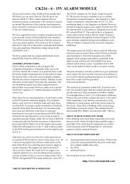
REMOTE CONTROL<br />
TRANSMITTER<br />
L<br />
R<br />
F<br />
B<br />
Encoding<br />
Circuitry<br />
Sequence<br />
of Radio<br />
Frequency<br />
Pulses<br />
CAR<br />
RECEIVER<br />
Steering Motor<br />
BLOCK DIAGRAM<br />
HOW IT WORKS<br />
Pulse Sequence,<br />
length depends on<br />
which command is<br />
being sent<br />
Filter/<br />
Amplifier<br />
Filter/<br />
Amplifier<br />
Decoding<br />
Circuitry<br />
27.9 MHz<br />
Signal<br />
Pulse Sequence,<br />
length depends on<br />
which command<br />
was sent<br />
Driving Motor<br />
ELECTRONIC ROAD MAPS<br />
TRANSMITTER SCHEMATIC<br />
RECEIVER SCHEMATIC<br />
7 8<br />
TROUBLESHOOTING<br />
OTHER AMERIKIT PRODUCTS<br />
Symptom: Car does not go in a straight line when you release the<br />
right control lever.<br />
• Use a non-Phillips type screwdriver to adjust the front wheels<br />
alignment control on the underside of the Bottom Frame, as in<br />
assembly step 14.<br />
Symptom: Car doesn’t work at all.<br />
• Make sure that the batteries in both the car and the Remote Control<br />
Transmitter are strong and that they are installed with the positive and<br />
negative terminals positioned properly. Alkaline or re-chargeable<br />
nickel-cadmium batteries are highly recommended, and new ones will<br />
last for 30-40 minutes of continuous use. Do not mix old and new, and<br />
and different types of batteries.<br />
• Make sure the ON/OFF switch is ON.<br />
• Move the Transmitter antenna close to the car antenna to be sure<br />
your range is not degraded. If range is degraded, see the symptom for<br />
reduced range (next).<br />
• Be sure that none of the wiring connections were broken, are<br />
contacting any other metal (creating a “short circuit”), or are wired<br />
wrong.<br />
• Be sure that there is no physical damage or “short circuits” on the<br />
Circuit Board.<br />
• Open the Remote Control Transmitter and check that the wiring<br />
connections are all intact and that there is no damage to its circuit board.<br />
Symptom: Front wheels do not turn or barely turn.<br />
• On some models LEFT/RIGHT commands are only sent if<br />
FORWARD/BACKWARD commands are also being sent, so try<br />
pressing both transmitter levers at the same time.<br />
• Lift up the front section (to remove friction with the ground) and see if<br />
the wheels turn now.<br />
• Turn one of the front wheels with your hand and be sure that the other<br />
wheel turns in the same direction and that the Steering Motor Gear is<br />
moved along the Front Wheels Steering Bar smoothly.<br />
• Check the wiring to the Steering Motor and your assembly of the front<br />
section.<br />
• Be sure that there is no physical damage or “short circuits” on the<br />
Circuit Board. If you have a voltmeter, you should measure about<br />
4VDC across the wires to the Steering Motor when the transmitter is<br />
activated.<br />
Symptom: Car has reduced range.<br />
• Make sure that the batteries in both the car and the Remote Control<br />
Transmitter are strong and that they are installed with the positive and<br />
negative terminals positioned properly.<br />
• Make sure your antenna is properly extended.<br />
• Nearby CB and amateur radio transmitters can interfere with your<br />
control of the AK-870. Try moving away from them.<br />
• Make sure the wire between the Circuit Board and the antenna in the<br />
car is intact and that the antenna screw is tight.<br />
• Be sure that there is no physical damage or “short circuits” on the<br />
Circuit Board.<br />
• Although tunable inductor L1 has been pre-aligned, you may need to<br />
adjust it for best performance. You need a very small screwdriver for<br />
this. Remove the top cover and flip the ON/OFF switches to on.<br />
Activate the transmitter and move it away from the car. Adjust tunable<br />
inductor L1 on the circuit board for best range. Be VERY GENTLE,<br />
since L1 is FRAGILE. It should turn easily. If you apply too much<br />
force you may break it.<br />
Symptom: Car runs even though the Remote Control Transmitter is off.<br />
• Disconnect the battery in your Transmitter to make sure it is not<br />
malfunctioning.<br />
• Nearby CB and amateur radio transmitters are interfering with your<br />
control of the AK-870. Try moving away from them.<br />
Symptom: Car does not go forwards/backwards or does so erratically.<br />
• Be sure all the car batteries are strong and all your wires make strong<br />
connections.<br />
• Make sure the wheels are all free of thread, lint, or hair and that the<br />
black rubber on the wheels is not coming off.<br />
• Spin the rear wheels with your hands. You should feel and hear the<br />
Middle and Motor gears spin smoothly, if not check your assembly of<br />
the rear section. Add Vaseline or grease if necessary.<br />
• Lift up the rear section (to remove friction with the ground) and<br />
disconnect the Driving Motor wires from the Circuit Board. Re-connect<br />
the Motor wires across a 1.5V battery with your hands, the wheels<br />
should spin smoothly. If nothing happens (the motor gear does not<br />
spin) then inspect your motor for problems.<br />
• The Rear Wheels gear must be tight on its rod and the Middle Gear<br />
must NOT be tight on its rod.<br />
• Be sure that there is no physical damage or “short circuits” on the<br />
Circuit Board. If you have a voltmeter, you should measure about<br />
1.5VDC across the wires to the Driving Motor when the transmitter is<br />
activated and the wheels are not turning, or about 4VDC when the<br />
wheels are spinning freely.<br />
Symptom: Light Bulb does not light.<br />
• Check the wires to the Light Bulb.<br />
• Check the bulb is not burnt-out.<br />
• Be sure that there is no physical damage or “short circuits” on the<br />
Circuit Board.<br />
If you need additional assistance or replacement parts, contact:<br />
Elenco <strong>Electronic</strong>s, Inc.<br />
150 W. Carpenter Avenue http://www.elenco.com<br />
Wheeling, IL 60090 e-mail: elenco@elenco.com<br />
(847) 541-3800 Fax: (847) 520-0085<br />
Say that you have version: E<br />
DO NOT contact your place of purchase as they will not be able to help you.<br />
Check out our website at http://www.elenco.com for our full line of electronic kits!<br />
<strong>Electronic</strong> Playground<br />
with Training Course Model EP-50<br />
This is our most popular kit. Our<br />
Telephone Kit will teach you all about<br />
communications. You will actually build<br />
your own phone and be able to make<br />
and receive calls. The clear plastic<br />
case lets you see all of the working<br />
components. It even has flashing neon<br />
lamps when the phone rings.<br />
NO TOOLS OR SOLDERING REQUIRED!<br />
This electronic science lab will teach you<br />
about electronics from A-Z. WIth this allin-one<br />
lab, you’ll learn about electronic<br />
parts, how to read schematics, and<br />
wiring diagrams. All this while building<br />
up to 50 different projects. Porjects<br />
include a finger touch lamp, magnetic<br />
bridge, voltmeter, morse code, alarm,<br />
transistor radio, metal detector, etc.<br />
Clear Telephone Kit<br />
with Training Course Model AK-750<br />
Talking Clock Kit<br />
with Training Course Model AK-220<br />
Build your own talking clock! It looks<br />
exactly like an ordinary analog clock, but<br />
it also announces the time with a voice at<br />
the press of a button on the top. The<br />
movement is driven by the speech circuit,<br />
thereby synchronizing the analog time<br />
and digital time. Learn about gears and<br />
how time is kept electronically.<br />
9 10 11<br />
12