Towbar Wiring - Volvo Owners Club
Towbar Wiring - Volvo Owners Club
Towbar Wiring - Volvo Owners Club

You also want an ePaper? Increase the reach of your titles
YUMPU automatically turns print PDFs into web optimized ePapers that Google loves.
TOWBAR WIRING<br />
This leaflet is prepared as a <strong>Club</strong> service to members. Previous versions of it were titled ‘<strong>Wiring</strong> a<br />
Vehicle For Trailer Towing’. The contents are believed correct at the time of publication. Please raise<br />
any queries with the <strong>Club</strong>'s Information Department<br />
Contents<br />
October 2006<br />
Contents....................................................................................................................................... 1<br />
1. Scope................................................................................................................................... 1<br />
2. Introduction......................................................................................................................... 2<br />
3. Which System Do You Need?............................................................................................ 2<br />
3.1 Pre-October 1979 Caravans ........................................................................................... 3<br />
3.2 October 1979 to 31 August 1998 Caravans.................................................................... 4<br />
3.3 1 September 1998 And Newer Caravans........................................................................ 5<br />
3.4 Some Continental-Built Caravans .................................................................................. 6<br />
3.5 General Design Points .................................................................................................... 7<br />
4. DIY vs Professional Fitting .............................................................................................. 12<br />
5. Checking A New Installation............................................................................................ 13<br />
5.1 Installation Check......................................................................................................... 13<br />
5.2 Functional Check.......................................................................................................... 13<br />
6. Fault Finding..................................................................................................................... 15<br />
6.1 Road Light Circuits ...................................................................................................... 15<br />
6.2 Supplementary Circuits ................................................................................................ 16<br />
7. Miscellaneous Matters ...................................................................................................... 17<br />
7.1 42V Electrical Systems................................................................................................. 17<br />
7.2 Glossary of Terms ........................................................................................................ 17<br />
8. Useful Contacts................................................................................................................. 18<br />
1. Scope<br />
This leaflet describes the wiring additions to a towing vehicle to make it suitable for<br />
towing. It is based on current UK practice, and on the relevant British and<br />
international standards, including the changes resulting from the introduction of<br />
European Standards for caravans from 1 September 1998. It is not intended as a set of<br />
installation instructions for tow bar wiring, and should not be used as such. Its purpose<br />
is:-<br />
• to provide advice in the correct specification of a tow bar wiring system<br />
• to allow an already-installed system to be checked for correctness<br />
• to diagnose common faults and problems in service
2<br />
2. Introduction<br />
Before a vehicle can be used for towing, it is necessary to fit a towing bracket,<br />
(probably) modify the direction indicator system and install the necessary socket(s) to<br />
power the caravan or trailer’s road lights and any internal auxiliary equipment. In the<br />
past, this was commonly considered a straightforward task for a competent DIY<br />
person. In recent years, however, the increasing complexity of vehicle electrical<br />
systems has made it increasingly difficult to obtain and interpret the technical<br />
information necessary to ensure that the required connections are made in a correct and<br />
safe manner.<br />
Some vehicles could be seriously damaged by the use of an ‘off the shelf’ tow bar<br />
wiring kit – with some others, the additional wiring would simply not work properly<br />
without extra components. Keeping up with this topic as new and revised models of<br />
vehicle are launched is a demanding task, and is certainly one which the <strong>Club</strong> does not<br />
have the resources to do. Do check with your intended manufacturer, retailer or fitter<br />
of the system, therefore, before making a final selection. If they are unfamiliar with<br />
the characteristics of your particular vehicle, it may be best to look elsewhere. For this<br />
reason, the <strong>Club</strong> recommends professional fitting, preferably by a specialist installer.<br />
Even if you do the work yourself, some fitting centres will check it over for you,<br />
especially if you have bought the towing bracket or other components from them.<br />
Note: Choosing a tow bar is discussed in the leaflet ‘Choice of Towing Bracket’.<br />
3. Which System Do You Need?<br />
There have been several variations in the wiring standards used for towing vehicles<br />
and caravans over the years. Which system you need depends mainly on the age of the<br />
caravan you are planning to tow, and to some extent on where the caravan was made:-<br />
• Caravan built before 1 October 1979 – Towing vehicle needs a single 12N seven<br />
pin socket. See Section 3.1.<br />
• Caravan built between 1 October 1979 and 31 August 1998 - Towing vehicle needs<br />
both 12N and 12S seven pin sockets. See Section 3.2. Note that some caravan<br />
manufacturers adopted changes to the 12S system prior to their formal introduction<br />
from 1 September 1998. Check carefully (via the handbook or dealer) the precise<br />
specification of 1997 and pre-September 1998 models.<br />
• Caravan built since 1 September 1998 - Towing vehicle needs both 12N and 12S<br />
seven pin sockets, but with modified 12S wiring. See Section 3.3.<br />
• Some Continental caravans, particularly if privately imported, or commercially<br />
imported in small numbers only - Towing vehicle needs a single 13 pin socket. See<br />
Section 3.4. An increasing number of towing vehicles are being fitted with 13 pin<br />
sockets as standard. Section 3.4 also describes this layout for these owners.
3<br />
3.1 Pre-October 1979 Caravans<br />
Few of these remain in their original specification now. Most caravans of this era were<br />
built with only a single black 7-pin plug (‘12N’ ie ’12 volt, normal’), which was<br />
adequate as they tended not to have reversing lights, rear fog lights, internal auxiliary<br />
batteries that required charging, nor fridges which could run on 12V. By the end of the<br />
70s, such features were becoming available, and in the case of rear fog lights, became<br />
compulsory for new trailers from 1 October 1979. This meant there were no longer<br />
sufficient circuits available on one 7-pin plug, and caravans made after this were<br />
therefore fitted with twin plugs (see next section). Note a pre-October 1979 caravan<br />
with twin plugs fitted will probably have been modified from its original specification.<br />
It is prudent to check that this was done correctly before attaching it to your vehicle.<br />
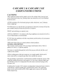
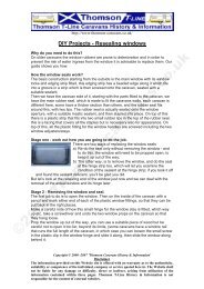
For an unmodified caravan, your vehicle needs a single 12N socket, wired as follows:-<br />
12N Socket To Suit Pre-October 1979 Caravans<br />
12N SOCKET VIEWED FROM<br />
PLUG SIDE OF SOCKET<br />
Notes<br />
TERMINAL COLOUR 12N SOCKET<br />
1 Yellow L H Indicator<br />
2 Blue Interior Lights etc<br />
3 White Return (Earth)<br />
4 Green R H Indicator<br />
5 Brown R H Tail Light<br />
6 Red Stop Lights<br />
7 Black L H Tail Light & Number Plate<br />
The power supply to the caravan via pin 2 is usually wired as permanently live, whether the vehicle<br />
engine is running or not. This enables 12V lights and water pump to be powered from the towing<br />
vehicle while on site, without requiring an auxiliary battery in the caravan. This means this system is<br />
inappropriate for running a 12V fridge, or charging a caravan battery, for the reasons given in Sections<br />
3.5.13 and 3.5.15 below.<br />
Except for the pin 2 connection, which was common practice, not a formal specification, sockets wired<br />
according to this description would comply with the now-superseded British Standard BS AU 149.<br />
Note that currently-available wiring kits will need to be modified to give this configuration, as far as the<br />
pin 2 connection is concerned.
3.2 October 1979 to 31 August 1998 Caravans<br />
4<br />
The bulk of caravans fall into this category. They are fitted with two 7-pin plugs (12N<br />
and 12S, ‘supplementary’). The 12S plug is coloured grey or white to distinguish it<br />
from the 12N one, and the associated socket has a cover flap in grey or white. The<br />
arrangement of pins and tubes is also different to prevent accidental connection of the<br />
wrong plug to the wrong socket. The 12N system now contains all of the legallyrequired<br />
trailer road light circuits. The 12S system includes reversing lights (not<br />
currently a legal requirement on trailers), plus the various auxiliary power connections<br />
required by most modern caravans. Strictly speaking, you only need to have the 12N<br />
system functioning to tow a caravan legally. However, most owners use at least some<br />
of the 12S circuits, so the required towing vehicle wiring is as follows:-<br />
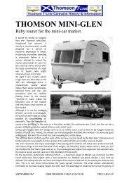
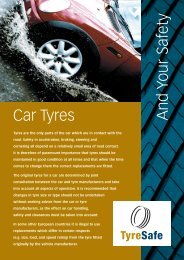
12N & 12S Sockets To Suit October 1979 to 31 August 1998 Caravans<br />
12N & 12S SOCKETS VIEWED FROM<br />
PLUG SIDE OF SOCKET 12N 12S<br />
TERMINAL COLOUR 12N SOCKET 12S SOCKET<br />
1 Yellow L H Indicator Reversing Light(s)<br />
2 Blue Fog Light(s) Caravan Battery Charging<br />
(Ignition Controlled Supply)<br />
3 White Return (Earth) Return (Earth)<br />
4 Green R H Indicator Interior Lights Etc (Permanent Supply)<br />
5 Brown R H Tail Light Sensing Device<br />
6 Red Stop Lights Fridge (Ignition Controlled Supply)<br />
7 Black L H Tail Light<br />
& Number Plate<br />
Not Used<br />
Notes<br />
The supplies to 12S pins 2 and 6 must be installed such that they are live only when the vehicle engine<br />
is running (see Sections 3.5.13 and 3.5.15 below).<br />
The supply to 12S pin 2 for caravan battery charging has been customary practice in the UK for many<br />
years. However, it has never been adopted into a British or other standard for tow bar wiring. It is,<br />
therefore, frequently ignored by vehicle manufacturers in their wiring kits.<br />
See section 3.5.16 for advice regarding 12S pin 2 if towing a continental-built caravan.<br />
With the exception of the 12S pin 2 connection as mentioned above, sockets wired according to these<br />
specifications will comply with British Standard BS AU 149a (12N) and BS AU 177a (12S). These<br />
standards are effectively identical to International Standards ISO 1724 (12N) and ISO 3732 (12S).
3.3 1 September 1998 And Newer Caravans<br />
5<br />
These are built to European standards, one of which defines the 12V wiring, and<br />
results in changes to the 12S system. (The 12N system remains the same.) An extra<br />
earth acts to separate the fridge power supply from other circuits, minimising the risk<br />
of overloading the return wire when several circuits are used together. Battery<br />
charging is officially included, but via pin 4, not pin 2, as was usual practice in the UK<br />
before, but never included in previous standards. Pin 4 also operates interior lights etc,<br />
but not at the same time as battery charging. Switching to achieve this is done in the<br />
caravan.<br />
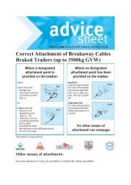
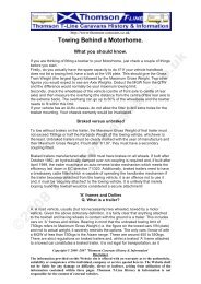
12N & 12S Sockets To Suit 1 September 1998 And Newer Caravans<br />
12N & 12S SOCKETS VIEWED FROM<br />
PLUG SIDE OF SOCKET 12N 12S<br />
TERMINAL COLOUR 12N SOCKET 12S SOCKET<br />
1 Yellow L H Indicator Reversing Light(s)<br />
2 Blue Fog Light(s) Sensing Device<br />
3 White Return (Earth) Return (Earth) For Pin 4<br />
4 Green R H Indicator Interior Lights etc or Caravan Battery<br />
Charging (Permanent Supply)<br />
5 Brown R H Tail Light Not Used<br />
6 Red Stop Lights Fridge (Ignition Controlled Supply)<br />
7 Black L H Tail Light<br />
& Number Plate<br />
Return (Earth) For Pin 6<br />
Notes<br />
The supply to 12S pin 6 must be live only when the vehicle engine is running (see Sections 3.5.15<br />
below).<br />
12S pins 3 and 7 should not be joined together at the socket. They should be taken separately to an<br />
earth point on the vehicle structure. Failure to do may result in overheating of the 12S plug and socket.<br />
12S pin 4 must be permanently live for both battery charging and interior light etc functions to operate.<br />
The fridge circuit must work correctly for switching of the pin 4 supply between these functions to<br />
occur.<br />
At the time of writing, the standards for vehicle wiring have not been updated to match the latest<br />
caravan wiring standard. The above specification complies with British Standard BS AU 149a (12N)<br />
and the effectively identical International Standard ISO 1724. BS AU 177a and ISO 3732 (12S) do not<br />
yet include the earth via pin 7, and hence this connection may be omitted by some makers and installers.<br />
See section 3.5.16 for advice regarding 12S pin 2 if towing a continental-built caravan.
3.4 Some Continental-Built Caravans<br />
Some Towing Vehicles With Manufacturer-Supplied Tow Bars<br />
6<br />
A single 13 pin connector is an alternative to the twin 7 pin system. This is used<br />
mainly on the continent, and hence may be seen on imported caravans, although most<br />
are either built with 7 pin plugs, or are modified to use them on arrival in this country.<br />
Models sold in very small numbers, or caravans imported privately, are most likely to<br />
have a 13 pin plug. <strong>Owners</strong> may wish to alter such caravans to the 7 pin system. For<br />
use without modification, the towing vehicle will need a single 13 pin socket as below.<br />
It is more likely that this system will be found on the towing vehicle, as several vehicle<br />
makers have adopted it as standard. Again, many owners may prefer to change to twin<br />
7 pin sockets. To use the 13 pin socket, however, it should be wired as below:-<br />
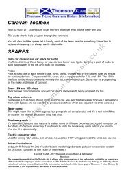
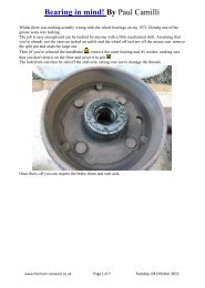
13 Pin Socket To Suit Some Continental Caravans<br />
& As Fitted To Some Recent Towing Vehicles<br />
13 PIN SOCKET VIEWED FROM<br />
PLUG SIDE OF SOCKET<br />
TERMINAL 13 PIN SOCKET TERMINAL 13 PIN SOCKET<br />
1 L H Indicator 8 Reversing Light(s)<br />
2 Fog Light(s) 9 Interior Lights etc or Caravan<br />
Battery Charging (Permanent<br />
Supply)<br />
3 Return (Earth) For Pins 1 To 8 10 Fridge (Ignition Controlled Supply)<br />
4 R H Indicator 11 Return (Earth) For Pin 10<br />
5 R H Tail Light 12 Sensing Device<br />
6 Stop Lights 13 Return (Earth) For Pin 9<br />
7 L H Tail Light & Number Plate<br />
Notes<br />
The supply to pin 10 must be live only when the vehicle engine is running (see Section 3.5.15).<br />
Pins 3, 11 and 13 should not be joined together at the socket. They should be taken separately to an<br />
earth point on the vehicle structure. Failure to do may result in overheating of the plug and socket.<br />
Pin 9 must be permanently live for both battery charging and interior light etc functions to operate. The<br />
fridge circuit must work correctly for switching of the pin 9 supply between these functions to occur.<br />
This system meets International Standard ISO 11446, and may also be referred to as ‘Jaeger’. At least<br />
one other 13 pin system exists (‘Multicon’), but is not a recognised standard, and is unlikely to be<br />
found.<br />
See section 3.5.16 for advice regarding pin 12.<br />
No colour convention for the wiring is defined in this standard.
7<br />
3.5 General Design Points<br />
3.5.1 Wire Specifications<br />
Specially-designed multi-core cables are available, and it is recommended that these<br />
are used. 12N cable has black outer insulation, and contains 7 wires (or 8 – see Fog<br />
Light section 3.5.9). 12S cable is grey or white, and also contains 7 wires. 13-core<br />
cable is available for use with 13-pin sockets. Each wire within these should be an<br />
appropriate cross-sectional area for its designated purpose, and where applicable<br />
should preferably be to the conventional colour codes indicated earlier. Note that<br />
vehicle makers do not always follow the conventional colour coding in their wiring<br />
kits.<br />
CIRCUIT CLUB RECOMMENDED MINIMUM WIRE SIZE Note 4<br />
Indicators<br />
Fog Light(s)<br />
Tail Lights<br />
Stop Lights<br />
Reversing<br />
Light(s) Note 1<br />
Interior Lights<br />
etc<br />
Caravan Battery<br />
Charging Note 2<br />
12N 12S 13-Pin<br />
1mm 2<br />
14 strands, 0.3mm dia.<br />
Current capacity 8.75A<br />
1.5mm 2<br />
21 strands, 0.3mm dia.<br />
Current capacity 13.0A<br />
1.5mm 2<br />
21 strands, 0.3mm dia.<br />
Current capacity 13.0A<br />
1.5mm 2<br />
21 strands, 0.3mm dia.<br />
Current capacity 13.0A<br />
Fridge Note 3 1.5mm 2<br />
21 strands, 0.3mm dia.<br />
Current capacity 13.0A<br />
Sensing Device 1.5mm 2<br />
21 strands, 0.3mm dia.<br />
Current capacity 13.0A<br />
Return (Earth) 2.0mm 2<br />
28 strands, 0.3mm dia.<br />
Current capacity 17.5A<br />
Notes<br />
White wire (pin 3):-<br />
2.5mm 2<br />
36 strands, 0.3mm dia.<br />
Current capacity 21.5 A<br />
Black wire (pin 7):-<br />
1.5mm 2<br />
21 strands, 0.3mm dia.<br />
Current capacity 13.0A<br />
1.5mm 2<br />
21 strands, 0.3mm dia.<br />
Current capacity 13.0A<br />
1.5mm 2<br />
21 strands, 0.3mm dia.<br />
Current capacity 13.0A<br />
2.5mm 2<br />
36 strands, 0.3mm dia.<br />
Current capacity 21.5 A<br />
2.5mm 2<br />
36 strands, 0.3mm dia.<br />
Current capacity 21.5 A<br />
1.5mm 2<br />
21 strands, 0.3mm dia.<br />
Current capacity 13.0A<br />
3 wires, each:-<br />
2.5mm 2<br />
36 strands, 0.3mm dia.<br />
Current capacity 21.5 A<br />
1. The larger gauge wire does not indicate a higher power demand than the other road lights, but<br />
merely results from the use of a larger standard size (1.5mm 2 ) cable in the 12S cable.<br />
2. The use of a larger section wire (eg 2.5mm 2 ) would be advantageous to give more reliable<br />
battery charging, due to a reduced voltage drop along the charging wire.<br />
3. The rating of the ‘standard’ wire is barely adequate for the fridge power supply. Better<br />
performance will be gained by up-rating this wire, with fridge manufacturers normally<br />
suggesting 2.5mm 2 , or even 4mm 2 , particularly if the supply powers a large fridge or<br />
fridge/freezer. Instead of running an additional separate wire to achieve this, it may be easier<br />
to combine the existing wire with an unused core in the 12S or 13 pin cable. Note that by<br />
doing this, however, the cable becomes non-standard, so check carefully that doing so will not<br />
interfere with other connections in your towing vehicle or caravan.<br />
4. Not all installations follow these recommendations. While the <strong>Club</strong> believes these represent<br />
‘best practice’, this does not mean that alternative specifications will not work adequately.
8<br />
3.5.2 Connector Advice<br />
Road light circuits are often connected to the main wiring loom of the towing vehicle<br />
via a multiway plug and socket in the boot. Independent (ie non-vehicle manufacturer<br />
supplied) wiring kits may not use this connection, and individual connections will need<br />
to be made, as will be the case for several of the supplementary circuits.<br />
Some wiring kits include snap-lock type connectors (eg ‘Scotchlok’), which are quick<br />
and cheap, but do not necessarily result in a secure, effective joint. Crimp connections,<br />
soldered joints, screw connectors or professional-type plug-in connectors are a better<br />
alternative for long-term reliability.<br />
3.5.3 Circuit Layout<br />
<strong>Wiring</strong> between the main vehicle loom and the sockets should be hidden neatly behind<br />
trim panels, load area carpeting etc, so that it is protected. Cables should be kept to the<br />
shortest practical length to minimise voltage drop problems, but with sufficient excess<br />
to allow sockets etc to be readily removed for inspection or maintenance.<br />
3.5.4 Socket Positioning<br />
Sockets should be accessible without undue difficulty, and adjacent to the tow ball.<br />
Unusual locations (eg under the bumper, or offset too far to the side) may result in the<br />
caravan cables either not reaching, or hanging too low and hitting the road.<br />
3.5.5 Bulb Failure Monitors<br />
Many towing vehicles use monitors to detect the failure of key road light bulbs. Tow<br />
bar wiring should be installed so as to retain the operation of these devices. Clear<br />
fitting instructions or a skilled installer may be necessary to ensure this is the case.<br />
3.5.6 Fuses<br />
Road light circuits will already be protected by fuses, but additional circuits which are<br />
added by fitting tow bar electrics should include their own protection. Fuses may be<br />
‘in-line’ (which look similar to domestic mains fuses) in cylindrical holders, or<br />
vehicle-type blade fuses. While both are acceptable, the blade type tends to give a<br />
better, more reliable contact. It is recommended that the individual supplies to the<br />
fridge, battery charging and interior light etc circuits are protected by separate fuses,<br />
typically of 15A rating. There will also be a main power supply taken from the vehicle<br />
battery from which these individual supplies are derived, and that should typically<br />
have a 25A rating fuse. Do not change any fuse to one of a different rating without<br />
confirming the acceptability of such a change with the supplier or installer of the<br />
system.
9<br />
3.5.7 Multiplexed <strong>Wiring</strong><br />
A small but growing number of vehicles are fitted with multiplexed wiring, either<br />
throughout the vehicle (eg Jaguar) or in certain sub-systems only (eg Peugeot). Such<br />
systems use individual wires for more than one purpose, and hence can be awkward to<br />
connect tow bar wiring to. Incorrect fitting may cause extensive and expensive harm.<br />
Extreme caution is advised before using an off the shelf wiring kit with such vehicles,<br />
and seeking the advice of an experienced fitter is recommended. Check with your<br />
vehicle manufacturer or dealer if unsure whether your vehicle includes such wiring.<br />
3.5.8 Indicator Circuits<br />
It may be necessary to fit a heavy-duty indicator relay to operate the additional caravan<br />
flashers without overloading the standard unit, or affecting its flashing rate. It is also a<br />
legal requirement that the towing vehicle ‘shall be equipped with an operational telltale<br />
for front and rear indicators (including any rear indicator on the rearmost of any<br />
trailers drawn by the vehicle)’ (Road Vehicle Lighting Regulations, 1989.) This telltale<br />
can be an audible or visual device. Some show the correct functioning of the<br />
indicators, perhaps via an instrument panel light or boot-mounted buzzer which signals<br />
in time with the flashers. Others operate by altering the standard flasher function to an<br />
alternative ‘warning’ signal if a fault is detected in the circuit. Note that this tell-tale<br />
function is sometimes neglected when the tow bar wiring is fitted – this is illegal.<br />
3.5.9 The Fog Light(s) Circuit<br />
One or two rear fog lights may be fitted – at least one is a legal requirement for<br />
caravans and other trailers built since 1 October 1979. Many owners find the<br />
reflection of the towing vehicle’s rear fog light(s) off the front of the caravan a<br />
distraction, and to avoid this, it is acceptable to disconnect the towing vehicle’s fog<br />
light(s) while towing, as long as the trailer ones still function. This can be done via a<br />
mechanical switch built into a suitably-equipped 12N socket, and operated by the<br />
insertion of the 12N plug. This system uses the extra wire in an 8-way 12N cable, or a<br />
separate wire can be used. An alternative is to fit a fog light cut-out relay, which<br />
senses power going to the caravan fog light, and automatically turns off the towing<br />
vehicle’s one(s).<br />
3.5.10 The Tail Light Circuit<br />
Power for the illumination of the caravan number plate is also taken from this circuit,<br />
along with power for front and side marker lights, if fitted.<br />
3.5.11 The Stop Light Circuit<br />
High-level stop (brake) lights are not required to be fitted to caravans, but if installed<br />
will operate from this circuit along with the main stop lights.<br />
3.5.12 The Reversing Light Circuit<br />
This circuit is not currently a legal requirement for caravans and trailers, but all<br />
modern caravans have reversing lights, and hence the use of this circuit is<br />
recommended.
10<br />
3.5.13 The Caravan Auxiliary Battery Charging Supply<br />
Most modern caravans are fitted with an auxiliary battery, which will often be charged<br />
via a mains charger while on site. If touring away from mains power, however, the<br />
facility to recharge the caravan battery from the towing vehicle while travelling is very<br />
useful. It is important, however, that charge is not taken from the towing vehicle<br />
battery to top up the caravan one, or else there may be insufficient charge left to restart<br />
the engine. To avoid this situation, the battery charging circuit is an ‘ignitioncontrolled’<br />
power supply from the towing vehicle ie charging only occurs while the<br />
towing vehicle engine is running. This may be achieved either by using a relay<br />
activated by the output of the alternator of the vehicle, or by means of a voltage sensor<br />
which detects the change in voltage in the towing vehicle circuits when the engine<br />
starts, and which then turns a relay on. A further reason to connect the circuit in this<br />
way is that it avoids the risk of the towing vehicle’s engine attempting to start from the<br />
caravan battery, if its own battery were to have failed. Such a situation could<br />
otherwise result in damage to both the caravan battery and the wiring throughout the<br />
outfit. The precise connections of the circuits to achieve this function vary from<br />
vehicle to vehicle, and hence are beyond the scope of this leaflet.<br />
Some owners like to be able to recharge their caravan battery in the boot of the towing<br />
vehicle, perhaps while out on a day trip with the caravan left on site. To do this, an<br />
additional wire from the battery charging supply, plus an earth connection, can be run<br />
to appropriate battery terminals (not crocodile clips, which are insufficiently safe) in<br />
the boot. Do make sure that the battery is safely located, cannot fall over, and that the<br />
boot is well ventilated. Do not use this facility to recharge batteries in both the caravan<br />
and the boot of the towing vehicle simultaneously.<br />
3.5.14 The Interior Lights etc Circuit<br />
This circuit is permanently live. Historically, this allowed the interior lights and water<br />
pump to be powered by the towing vehicle while on site, thus avoiding the need for a<br />
dedicated caravan battery. This practice is virtually unknown now, but the facility is<br />
useful while travelling, or in the event of the caravan battery running down. This<br />
circuit is also used to provide caravan battery charging on recent caravans (see above).<br />
3.5.15 The Fridge Power Supply<br />
Most caravan owners use the facility to power their caravan fridge from the towing<br />
vehicle while travelling, thus keeping the fridge cool during the journey. Since the<br />
fridge is a relatively high-powered device the towing vehicle battery needs to be<br />
protected against being drained by the caravan fridge, if the towing vehicle engine is<br />
not running (while parked, or on a ferry, say). This is done by connecting the fridge<br />
circuit to an ‘ignition-controlled’ power supply from the towing vehicle. This may be<br />
achieved either by using a relay activated by the output of the alternator of the vehicle,<br />
or by means of a voltage sensor which detects the change in voltage in the towing<br />
vehicle circuits when the engine starts, and which then turns a relay on. The precise<br />
connections of the circuits to achieve this function vary from vehicle to vehicle, and<br />
hence are beyond the scope of this leaflet.
11<br />
3.5.16 Sensing Device<br />
The wiring standards for 12S and 13 pin systems include provision for a ‘sensing<br />
device’. This is intended to allow the towing vehicle to detect that a trailer is present,<br />
and thus make any appropriate adjustments (eg turn off towing vehicle fog lights;<br />
adjust engine/gearbox settings etc). The <strong>Club</strong> is not currently aware of any towing<br />
vehicle which uses this facility, and hence this circuit can usually be ignored. The<br />
exception is if towing a continental-built caravan. In this case, ensure that neither 12S<br />
pin 2 nor 12S pin 5 in the caravan is connected to earth. If it is, then a dead short may<br />
occur, blowing a fuse or causing damage to the circuits. To avoid this, disconnect the<br />
relevant circuit in either the caravan or towing vehicle before hitching up. No such<br />
possible conflicts should occur with UK-built caravans, nor if using a 13 pin<br />
connector.<br />
3.5.17 Earths<br />
Each circuit is completed via a ‘return’ or ‘earth’ connection. Unlike most towing<br />
vehicles, the chassis or body of the caravan is not used to provide the earth path –<br />
instead discrete wires are used. Since several circuits often share the same earth wire,<br />
these wires needs to be able to handle quite high currents when several devices are<br />
operating simultaneously. As the number and power of devices in caravans has<br />
increased over the years, the relevant standards have added extra earth connections to<br />
ensure that these wires are not overloaded. To allow this to work effectively, it is<br />
essential that these wires are not connected together, either in the caravan, or within<br />
the towing vehicle, until they are attached to an earthing point on the body of the<br />
towing vehicle. Joining earth wires in the 12S socket, say, or elsewhere can result in<br />
local sections of the circuit (particularly the 12S plug and socket) overheating and<br />
failing.<br />
3.5.18 Adapters and Extensions<br />
Most commonly needed is an adapter lead which connects to a towing vehicle’s single<br />
13 pin socket, and the caravan’s two 7 pin plugs. Such leads are sometimes included<br />
when the towing vehicle is bought, or may be an ‘extra’ available through the vehicle<br />
dealer, often at a significant price. Alternative leads are obtainable from larger<br />
accessory shops, or from component specialists. Many owners may prefer to have the<br />
13 pin socket replaced with 7 pin ones, however, assuming it is practical for this to be<br />
done. The use of an adapter lead can make the caravan connections too long, and there<br />
is a risk of them dragging on the ground while travelling. Make sure that any such<br />
adapter lead includes all of the required wires for your caravan.<br />
With a few vehicles with unusually positioned sockets, it may be necessary to use short<br />
extension leads in order to get the caravan leads to reach. Again, these (or the<br />
components to make them up) are available from good accessory suppliers.<br />
Finally, a longer extension (typically 3m) may be used to link the towing vehicle to the<br />
caravan while on site, so that appliances can be powered from the towing vehicle<br />
battery instead of the caravan’s one. For most caravans, this will be a 12S extension –<br />
for some of the older ones it would be a 12N extension (see Section 3.1).
12<br />
4. DIY vs Professional Fitting<br />
As stated earlier, DIY fitting of tow bars and wiring is much less common than it once<br />
was. If you choose this route, however, check the following points first:-<br />
• Use only good quality, new parts – they shouldn’t let you down while on holiday.<br />
• Make sure you know the specification of your towing vehicle before you start – eg<br />
does it have bulb failure monitors, multiplexed wiring etc?<br />
• Take advice from your supplier regarding unusual features of your vehicle – they<br />
should have such details, and if not, can you trust them to sell you the correct kit?<br />
• Most vehicle dealers offer only a full ‘supply and fit’ service, and few know much<br />
detail about tow bar wiring anyway. By all means ask for advice, but don’t expect<br />
detailed help. They should confirm if multiplexed wiring is used or not, however.<br />
• Try to see a copy of the fitting instructions before you buy. This is not always<br />
possible, but can give a useful indication of how easy or difficult a job will be.<br />
• Check everything as you fit it, and check it all again before you first power up and<br />
hitch to the caravan. Remember that any damage resulting from any fitting errors<br />
will be your responsibility, and your vehicle warranty etc will not cover it.<br />
If you have the wiring fitted for you, there is a choice between using a vehicle dealer or<br />
an independent specialist.<br />
Vehicle dealers do not fit tow bars and wiring everyday, so they may be relatively<br />
inexperienced at it. Make sure they understand what you expect from the wiring<br />
system (use the specifications from Sections 3.1 to 3.4, if need be). Generally, few<br />
problems result from the 12N system (or the 12N ‘half’ of a 13 pin system). Frequent<br />
problems arise with the 12S circuits, however, with circuits either missing entirely, or<br />
not being correct (eg permanently live when it should be ignition-controlled). You<br />
may not get much choice of system at a dealer either – 13 pin electrics and a swanneck<br />
style tow bar do not suit all caravanners! The advantage of a dealer-fitted system<br />
is the work should be properly guaranteed, and your vehicle warranty will not be<br />
affected.<br />
In contrast, for most independent tow bar fitters this is a major part of their business.<br />
They should, therefore, be both experienced and knowledgeable. This is generally the<br />
case, but there have been enough reports of ‘cowboy’ fitters to advise a degree of<br />
caution. Look for well-established companies, and question them on their knowledge<br />
of your particular vehicle. Bear in mind that damage to the vehicle through the fitting<br />
of non-manufacturer approved tow bar wiring may not be covered by the vehicle<br />
warranty, so make sure the fitter’s work is fully guaranteed.<br />
For peace of mind, a nationwide scheme has recently been set up by the National<br />
Trailer and Towing Association, the trade body for tow bar fitters and trailer<br />
manufacturers and retailers. To join the ‘Quality Assured’ Scheme, a fitting outlet<br />
must pass assessment for competence, and will provide a thorough guarantee of work<br />
carried out. The NTTA provide the only specialist tow bar fitting and tow bar electrics<br />
training recognised as satisfying an NVQ level, and additionally have excellent<br />
technical back-up advice available to their members for ‘awkward’ vehicles. Hence,<br />
their accredited fitters should provide some of the best installation services available.<br />
The scheme is new, but the number of accredited outlets should increase steadily over<br />
time. Contact the NTTA on 01926 335445 for details of the nearest outlet in your area.
5. Checking A New Installation<br />
13<br />
If you have installed the wiring yourself, you will hopefully have carried out checks as<br />
you go, but a final functional check will still be needed, of course. If the system has<br />
been installed for you, then an installation check may also be prudent:-<br />
5.1 Installation Check<br />
• Are all the components (sockets etc) securely fitted, and located in a sensible place,<br />
such that you can readily insert and remove the caravan plugs?<br />
• Is the wiring neat, and not vulnerable to damage, especially in the luggage<br />
compartment?<br />
• Can you identify where all the key components (eg fuses, relays) are fitted, in case<br />
of future problems?<br />
• Have sufficient fuses of appropriate ratings been fitted?<br />
• Do the connections between the tow bar wiring and the main vehicle wiring loom<br />
look adequate and secure?<br />
• Has the point where the tow bar wiring from the sockets enters the towing vehicle<br />
been protected with a rubber grommet or seal to protect the cables from abrasion,<br />
and prevent water penetration into the towing vehicle?<br />
• Is the point where the cable enters the back of the socket fitted with a rubber seal,<br />
to help keep water out of the socket wiring?<br />
• Have any trim panels which were removed during the installation been correctly<br />
and securely refitted, using all of their fixings?<br />
• Have you been given documentation (eg fitting instructions, specification sheet etc)<br />
which gives details of the components which have been fitted? These may be very<br />
useful during fault checking or if components need to be replaced in the future.<br />
Keep such details with the towing vehicle’s handbook.<br />
5.2 Functional Check<br />
5.2.1 Road Lights<br />
• Do all of the towing vehicle’s lights still work without the caravan attached?<br />
• Attach a test device, multimeter, trailer lighting board or the caravan. Note that in<br />
some situations, attaching anything other than a caravan may not result in the<br />
correct load being applied to the electrical system, and hence may not show up all<br />
faults. In the vast majority of cases, however, a test device or trailer board is<br />
adequate and often more convenient.<br />
• Check each road light circuit in turn. Make sure that the towing vehicle’s lights<br />
remain operational in addition to the caravan’s.<br />
• Check road lights in combination – eg head/tail lights, fog light and indicators<br />
together, and make sure that the circuits are not interfering with each other.<br />
5.2.2 Supplementary Functions<br />
• These are best checked either by connection to the caravan, or with a multimeter.<br />
• With a multimeter, check that there is voltage at the battery charging, fridge and<br />
interior lights pins on the socket while the engine is running, but that battery<br />
charging and fridge supplies turn off when the engine is stopped.
14<br />
• If using the caravan, disconnect power from the caravan battery, then attach the<br />
caravan plug to the towing vehicle. Check for operation of the interior lights with<br />
the engine not running. Switch the fridge to 12V operation, and check it works<br />
only when the engine is running. Check for power at the positive connector for the<br />
caravan battery is present only when the engine is running.
15<br />
6. Fault Finding<br />
6.1 Road Light Circuits<br />
No Road<br />
Lights Work<br />
Caravan<br />
Indicators<br />
Do Not Flash<br />
Only One<br />
Indicator<br />
Flashes<br />
Indicators<br />
Flash Dimly,<br />
Or At Wrong<br />
Rate<br />
Wrong<br />
Indicator<br />
Flashes<br />
Other Lights<br />
Do Not Work<br />
Indicator<br />
Tell-Tale<br />
Does Not<br />
Work<br />
Indicator<br />
Tell-Tale<br />
Works w/o<br />
C’van<br />
Fuses Blow<br />
Battery<br />
Connected &<br />
Functional?<br />
<br />
12N Or 13 Pin<br />
Plug Inserted<br />
Correctly?<br />
<br />
<br />
<br />
<br />
<br />
12S Plug<br />
Inserted<br />
Correctly?<br />
<br />
Check<br />
Connections<br />
On Plug &<br />
Socket<br />
<br />
<br />
<br />
<br />
<br />
<br />
<br />
<br />
<br />
Check <strong>Wiring</strong><br />
Connections<br />
To Caravan<br />
Lights<br />
<br />
<br />
<br />
<br />
<br />
<br />
<br />
Check<br />
Connections<br />
Between<br />
Socket Cable<br />
& Main <strong>Wiring</strong><br />
Loom<br />
<br />
<br />
<br />
<br />
<br />
<br />
<br />
<br />
<br />
Check Bulbs<br />
<br />
<br />
<br />
<br />
Check Vehicle<br />
Fuses<br />
<br />
<br />
<br />
<br />
Check<br />
Indicator Relay<br />
<br />
<br />
<br />
<br />
Check For<br />
Moisture Or<br />
Corrosion In<br />
Plug, Socket<br />
Or Caravan<br />
Lights<br />
<br />
<br />
<br />
<br />
Check<br />
Exposed<br />
Cables For<br />
Damage
16<br />
6.2 Supplementary Circuits<br />
Ignition Controlled<br />
Supply Does Not<br />
Work<br />
Ignition Controlled<br />
Supply Works All<br />
The Time, Even<br />
When Engine Is Off<br />
Ignition Controlled<br />
Supply Cycles On &<br />
Off<br />
Ignition Controlled<br />
Supply Does Not<br />
Turn Off Promptly<br />
When Engine Stops<br />
Ignition Controlled<br />
Supply Turns Off<br />
When Other<br />
Accessories In<br />
Relay Feels Hot<br />
Permanent Supply<br />
Does Not Work<br />
12S Plug & Socket<br />
Feels Hot<br />
Check<br />
Battery<br />
Condition &<br />
That<br />
Terminals<br />
Are Secure<br />
<br />
<br />
<br />
<br />
Check<br />
Alternator<br />
Output<br />
<br />
12S Or 13<br />
Pin Plug<br />
Inserted OK?<br />
<br />
<br />
<br />
Check<br />
Connections<br />
In Plug &<br />
Socket<br />
<br />
<br />
<br />
<br />
<br />
<br />
Check<br />
Connections<br />
Between<br />
Socket Cable<br />
& Main<br />
<strong>Wiring</strong> Loom<br />
<br />
<br />
<br />
<br />
<br />
Check Fuses<br />
<br />
<br />
Faulty Relay<br />
<br />
<br />
<br />
Adjust<br />
Sensitivity Of<br />
Relay<br />
<br />
<br />
<br />
<br />
Main Power<br />
Feed Cable<br />
From Battery<br />
Too Thin<br />
<br />
Fuse In Main<br />
Power Feed<br />
Cable From<br />
Battery Too<br />
Small<br />
<br />
Check Earth<br />
Wires Are<br />
Not Joined<br />
Together<br />
<br />
Check<br />
Exposed<br />
Cable For<br />
Damage<br />
<br />
<br />
Normal, But<br />
Move Unit<br />
Away From<br />
Heat<br />
Sensitive<br />
Surfaces<br />
<br />
Correct<br />
Function –<br />
Too Heavy<br />
Drain On<br />
Vehicle<br />
System
17<br />
7. Miscellaneous Matters<br />
7.1 42V Electrical Systems<br />
The motor industry has decided that the days of 12V systems in vehicles are numbered.<br />
Over the next few years, they plan to treble the nominal voltage at which vehicle<br />
systems operate. Currently, vehicle alternators produce around 14V, and vehicle<br />
batteries are around 12V. In due course, the battery voltage will be increased to 36V,<br />
while the alternator output rises to 42V. The reasons for this are twofold. Firstly, the<br />
power requirements within a typical vehicle have increased by 50% over the last 20<br />
years, and the existing system cannot be stretched much further. Secondly, by raising<br />
the voltage, it is easier to introduce higher powered sub-systems, such as electric<br />
power steering and electric air conditioning. By taking direct loads off the engine, it is<br />
believed that such sub-systems will enable fuel economy to be increased significantly.<br />
Completely 42V systems are predicted as appearing by 2007, but hybrid 42/14V<br />
systems may appear around 2004. Clearly, this will impact on the tow bar electrics,<br />
and the <strong>Club</strong> is monitoring this situation closely to ensure that caravanners’ interests<br />
are protected. At the time of writing, however, it is unclear how the industry will<br />
modify many of the more fundamental vehicle electrical sub-systems, and hence there<br />
is no indication yet what will be adopted for tow bar wiring. In the short to medium<br />
term, though, it is likely that caravans will remain as they are at present, with higher<br />
voltage vehicles needing the addition of a step down unit to deliver 12V to the caravan.<br />
7.2 Glossary of Terms<br />
Some of the terminology used in this leaflet may benefit from further explanation:-<br />
Cable<br />
Circuit<br />
Load<br />
Loom<br />
Monitor<br />
Pin<br />
Relay<br />
Return<br />
The term cable has been used to describe a conductor which is made up of<br />
a number of separately insulated wires (eg the lead to the 12S socket).<br />
A path for electricity from a power supply (eg a battery) via a wire to a<br />
load, and back to the power supply via an return wire.<br />
A device powered by electricity.<br />
The network of wires and cables throughout the body of the towing<br />
vehicle.<br />
A device which measures an effect and generates a signal as a result of this<br />
– eg it might indicate whether a light is on or not.<br />
The male half of the circuit connection in the car to caravan plug and<br />
socket. Note that sockets are usually described as being ‘7 pin’ or ‘13 pin’<br />
even if the socket half of the connector actually contains a mixture of pins<br />
and tubes, or even just tubes!<br />
A switch which is triggered by a signal (perhaps from a monitor) which<br />
results in a circuit being turned on or off (eg the fridge power supply).<br />
The wire which completes the electrical circuit from the load back to the<br />
power supply. Also commonly know as an ‘earth’. Within most towing<br />
vehicles, return connections are made via the metal of the vehicle body or<br />
chassis, thus reducing the number of separate wires needed to run the entire<br />
length of the vehicle.
18<br />
Sensor<br />
Short<br />
Tube<br />
Wire<br />
See Monitor.<br />
A direct (and usually inadvertent) linkage between a power supply and a<br />
return (earth) connection, without there being a load in between. The<br />
absence of a load means there is negligible resistance to the flow of<br />
electricity, usually resulting in a very high current flow, and an associated<br />
risk of overheating, if the circuit is not protected by a suitable fuse.<br />
The female half of the circuit connection in the car to caravan plug and<br />
socket.<br />
In this leaflet, the term wire has been used to describe a single insulated<br />
conductor (eg the cable to the 12S socket is made up of 7 separates wires).<br />
8. Useful Contacts<br />
Hella Ltd.<br />
Wildmere Industrial Estate<br />
Banbury<br />
Oxon OX16 3JU<br />
Maypole Limited<br />
54 Kettleswood Drive<br />
Woodgate Business Park<br />
Birmingham B32 3DB<br />
Towsure<br />
151 - 183 Holme Lane<br />
Hillsborough<br />
Sheffield<br />
South Yorks S6 4JR<br />
Ryder Towing Equipment Ltd<br />
Alvanley House<br />
Alvanley Industrial Estate<br />
Stockport Road East<br />
Bredbury<br />
Stockport<br />
Cheshire<br />
SK6 2DJ<br />
National Trailer & Towing<br />
Association:<br />
1 Alveston Place<br />
Leamington Spa<br />
Warwickshire CV32 4SN<br />
Tel 01295 272233<br />
Fax 01295 225480<br />
hella.uk@hella.com<br />
www.hella.co.uk<br />
Tel 0121 4233011<br />
Fax 0121 4233020<br />
maypole@maypole.ltd.uk<br />
www.maypole.ltd.uk<br />
Tel 0114 250 3000<br />
Fax 0800 444434<br />
www.towsure.com<br />
Tel 0161 4301120<br />
Fax 0161 4308140<br />
www.rydertowing.co.uk<br />
Tel 01926 335445<br />
Fax 01926 335445<br />
www.ntta.co.uk<br />
<strong>Wiring</strong> Kits, Relays,Adapter<br />
Leads etc<br />
<strong>Wiring</strong> Kits, Relays, Adapter<br />
Leads etc<br />
Components by Mail Order –<br />
<strong>Wiring</strong> Kits, Cable, Relays,<br />
Plugs, Sockets etc<br />
Relays, Monitors etc<br />
‘Quality Assured’ Tow Bar<br />
Fitters<br />
© The Caravan <strong>Club</strong> 2006