Table of Contents - DSpace@UM
Table of Contents - DSpace@UM
Table of Contents - DSpace@UM

Create successful ePaper yourself
Turn your PDF publications into a flip-book with our unique Google optimized e-Paper software.
Chapter 3<br />
Methodology<br />
3.1 Introduction<br />
Bennett et al (2002) defined that a methodology is a set <strong>of</strong> general principles that guide<br />
a practitioner to the choice <strong>of</strong> particular method suited to a specific task or project. In<br />
the domain <strong>of</strong> information system, a methodology consists <strong>of</strong> an approach to s<strong>of</strong>tware<br />
development, a set <strong>of</strong> techniques and notations that support the approach, a life cycle<br />
model to structure the development process, and a unified set <strong>of</strong> procedures and<br />
philosophy.<br />
3.2 System Development Methodology<br />
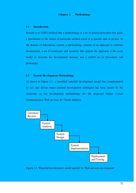
As shown in Figure 3.1 , a modified waterfall development model that complemented<br />
by use case driven object-oriented development techniques has been chosen by the<br />
researcher as the development methodology for the proposed Online Colour<br />
Communication Web services for Textile Industry.<br />
Literature<br />
Review<br />
System<br />
Analysis<br />
System<br />
Design<br />
System<br />
Implementation<br />
Deployment<br />
and Testing<br />
Figure 3.1: Waterfall development model applied for Web services development<br />
52
The project kicked-<strong>of</strong>f by conducting literature review on the current practices adopted<br />
by most <strong>of</strong> the companies involving in the colour communication process <strong>of</strong> textile<br />
industry, current existing electronic colour communication applications in the industry,<br />
Web services technology, as well as the potential technologies that would be used to<br />
develop this project.<br />
The domain knowledge and the research materials collected by the researcher at the<br />
stage <strong>of</strong> literature review serve as the input for the following stage, namely system<br />
analysis. In this stage, use case driven object-oriented technique will be used to elicit the<br />
system requirements.<br />
During system analysis, the requirements are captured and modelled in the form <strong>of</strong> use<br />
case diagrams which in the later stage <strong>of</strong> system analysis, each use case will be further<br />
translated into several class diagrams that are able to realize the requirements captured<br />
by the use case itself.<br />
The next stage <strong>of</strong> the development process is system design. Again, the deliverables<br />
produced by the researcher at the previous stage will be used as the input for designing<br />
and refining the system. The class diagrams modelled by the researcher based on use<br />
case driven object-oriented technique will be further refined with object attributes and<br />
methods. Database design that includes the effort <strong>of</strong> creating database tables, defining<br />
table attributes and performing normalization will also be conducted during the stage <strong>of</strong><br />
system design.<br />
System implementation takes place after the system design stage. It involves coding and<br />
development efforts which translate the design <strong>of</strong> the system into concrete outcome.<br />
The final stage <strong>of</strong> the development is deployment and testing. The complete developed<br />
53
system will be deployed on the server. Various types <strong>of</strong> tests will be conducted in order<br />
to verify and validate the correctness <strong>of</strong> the system.<br />
3.3 Justification for Choosing Waterfall Development Model<br />
The justification for the researcher to choose waterfall model as the system development<br />
methodology are as follows:-:<br />
i. It encourages proper planning before starting any phase in the development process.<br />
ii. Misinterpretation <strong>of</strong> the system may surface early and could be rectified before the<br />
system become too complicated to make any changes or enhancement on it.<br />
iii. It presents a very high level view <strong>of</strong> what goes along throughout the entire<br />
development cycle, and it suggests to the researcher the sequence <strong>of</strong> activities he<br />
would expect to encounter.<br />
iv. Its simplicity makes it relatively easy to be explained to various project<br />
stakeholders.<br />
3.4 Use Case Driven Object-oriented Development Technique<br />
Cook and Daniels (1994) pointed out that object-oriented methodology is an approach<br />
based on the development <strong>of</strong> self-contained modules or objects that can be easily<br />
replaced, modified and reused. The development techniques applied under this approach<br />
encourage the system stakeholders to view the world as a system <strong>of</strong> corporative and<br />
collaborating objects. This is very different from the traditional development techniques<br />
where the development philosophy is based on functions and procedure calls.<br />
The use case driven object-oriented approach provides a mechanism for mapping from<br />
real world problems to abstraction from which s<strong>of</strong>tware can be developed effectively<br />
(Bennett et al, 2002). It provides conceptual structures that help to deal with modelling<br />
complex<br />
during its incremental evolution along the development life cycle.<br />
54
3.5 Justification <strong>of</strong> Choosing Use Case Driven Object-oriented Technique<br />
The following is the justification why the researcher has chosen use case driven objectoriented<br />
development technique to complement the development life cycle based on<br />
waterfall model:-<br />
i. To cater the technical nature <strong>of</strong> the system developed by using object-oriented<br />
programming language<br />
As this project will be developed under waterfall development process model that was<br />
originated and evolved under the requirements <strong>of</strong> traditional structural development<br />
approach, it is lacking <strong>of</strong> the development nature that could cater the technical needs <strong>of</strong><br />
the system developed under object-oriented programming language. Therefore, the<br />
object oriented techniques had been chosen by the researcher to complement the<br />
shortcomings <strong>of</strong> traditional waterfall development model.<br />
ii. It provides traceability for user requirements across all development phases<br />
Use case driven object-oriented analysis and design technique provides traceability for<br />
user requirements right from requirement gathering phase until system testing phase.<br />
Under this development technique, initially, the requirements are being elicited and<br />
modelled from use case diagrams, followed by use case realization activities that<br />
translate the use case modelling into collaboration diagrams and class diagrams. During<br />
the design stage and implementation stage, the analysis class diagrams and the<br />
associations among the classes will be transformed into programming codes. When the<br />
researcher finally comes to the system testing stage, he could easily use the information<br />
gathered during the use case modelling stage as the input to for the required validation<br />
and verification testing.<br />
55
3.6 Unified Modelling Language<br />
Unified Modelling Language is the powerful modelling language that has been widely<br />
applied in the object-oriented development techniques. According to Scott (2001),<br />
Unified Modelling Language (UML) is a graphical language for visualizing, specifying,<br />
constructing, and documenting the artefacts <strong>of</strong> a s<strong>of</strong>tware intensive system. It helps the<br />
participants in a s<strong>of</strong>tware development efforts build models that will enable them to<br />
visualize the system, specify the structure and behaviour <strong>of</strong> the system, construct the<br />
system, and document the decisions made along the way.<br />
By using UML modelling techniques, every complex system is best approached through<br />
a small set <strong>of</strong> nearly independent views <strong>of</strong> a model as single view is not sufficient to<br />
visualize the overall aspects <strong>of</strong> a system (Booch and Eykholt, 1998).<br />
Bahrami (1999) summarized the nine mostly used UML graphical diagrams into four<br />
categories as the following. These graphical diagrams are very useful in modeling the<br />
static structure and dynamic behaviour <strong>of</strong> the system.<br />
1. Class diagram (Static)<br />
2. Use case diagram<br />
3. Behaviour diagram (dynamic)<br />
3.1 Interaction diagram<br />
3.1.1 Sequence diagram<br />
3.1.2 Collaboration diagram<br />
3.2 State chart diagram<br />
3.3 Activity diagram<br />
4. Implementation diagram<br />
4.1 Component diagram<br />
4.2 Deployment diagram<br />
56
3.6.1 Use Case Diagram<br />
Use case modeling is one <strong>of</strong> the UML modeling technique that use by the researcher to<br />
capture the goals <strong>of</strong> the users and the responsibility <strong>of</strong> the system to the users. In other<br />
words, use cases are scenarios for understanding system requirements. (Bahrami, 1999)<br />
Every use case is a sequence <strong>of</strong> actions that an actor performs within a system to<br />
achieve a particular goal (Scott, 2001). Use case modeling is being applied in this<br />
project to capture functional requirements <strong>of</strong> the system.<br />
3.6.2 Sequence Diagram<br />
UML Sequence Diagrams are an easy and intuitive way <strong>of</strong> describing the behaviour <strong>of</strong> a<br />
system by viewing the interaction between the system and its environment. Sequence<br />
Diagrams are interaction diagrams which capture the behaviour <strong>of</strong> a single use case,<br />
besides showing the pattern <strong>of</strong> interaction among objects. (Bahrami, 1999) A sequence<br />
diagram shows an interaction arranged in a time sequence. Sequence diagram is being<br />
applied in this project to capture the behavioural aspects <strong>of</strong> the proposed system.<br />
3.6.3 Collaboration Diagram<br />
Collaboration diagram is another type <strong>of</strong> UML interaction diagram in which describes<br />
and models the interactions and associations among classes. These interactions are<br />
modelled as exchanges <strong>of</strong> messages between classes through their associations (Albir,<br />
1998). Bahrami (1999) pointed out a major difference between sequence diagram and<br />
collaboration diagram as in a sequence diagram: the arrows which indicate the messages<br />
sent within the given use case normally proceed in one direction across the page to<br />
reflect the sequence <strong>of</strong> message order sending over timeline; but in collaboration<br />
diagram, the sequence is indicating by numbering the messages.<br />
57
3.6.4 Class Diagram<br />
UML class diagram is the main static analysis diagram that shows the static structure <strong>of</strong><br />
the model. A class is drawn as a rectangle with three components separated by<br />
horizontal lines. The top compartment holds the class name; the middle compartment<br />
holds the attributes <strong>of</strong> the class; while the bottom compartment holds a list <strong>of</strong><br />
operations. (Bahrami, 1999)<br />
3.6.5 Use Case Realization<br />
In the early stage <strong>of</strong> system analysis, use cases are used to build an initial model based<br />
on users' requirements for a new system (Bennett et al, 2002).<br />
Since the use cases are rather high level and concentrate on a user-centred view <strong>of</strong> the<br />
system, it needs to be translated into analysis diagrams, which serves as the primary<br />
models for describing the internal structure and behaviour <strong>of</strong> the proposed system.<br />
(Bennett et al, 2002)<br />
For this purpose, the use cases will be translated into analysis class diagrams that will<br />
also form a basis for the later design class diagrams, from which the executable code<br />
will be developed.<br />
The activity that used to translate use cases into class diagrams is known as use case<br />
realization, which uses collaboration diagrams to help with transition from use cases to<br />
class diagrams.<br />
The notations used by the researcher during the process <strong>of</strong> modelling class diagrams<br />
help to analyse in greater detail the model <strong>of</strong> requirements that is initially expressed as<br />
use cases. The use <strong>of</strong> class diagram related notation include elaborating the class<br />
58
definitions by using attributes and operations, and analysing the logical structure and<br />
relationship between classes by using associations.<br />
3.7 Research Techniques<br />
Various research techniques were being used in this research in order to gather<br />
necessary information which serves as the building blocks for subsequent analysis,<br />
design and development efforts:<br />
These techniques are as follows:<br />
i. Study <strong>of</strong> existing systems<br />
A few existing systems were analyzed in order to gain ideas on the features to be<br />
included in the proposed project. The review done on the existing systems helped the<br />
researcher to compare and evaluate their respective strengths and weaknesses with the<br />
proposed architecture.<br />
ii. Review <strong>of</strong> technologies<br />
The review on technologies such as Web services, Apache AXIS framework, Java<br />
programming language, Apache Tomcat Web server and so on gave the researcher<br />
better understanding on the strengths and constraints <strong>of</strong> the technologies to be used to<br />
develop the proposed system. It helps the researcher in determining the requirements<br />
that could be included into the system based on the technologies supported.<br />
iii. Discussion<br />
Useful advice and ideas were given by the supervisor throughout the entire project life<br />
cycle. The exchange <strong>of</strong> ideas between the supervisor and the researcher enabled the<br />
researcher to overcome several bottlenecks encountered during the development process.<br />
59
iv. Library Research and Internet Research<br />
Library provides a lot <strong>of</strong> reading materials that are useful for the research <strong>of</strong> this project.<br />
Books, journals, dissertations in the main library <strong>of</strong> the University <strong>of</strong> Malaya provide<br />
valuable information for analysing, designing, developing and evaluating the proposed<br />
system.<br />
Besides, there are many informative articles related to the business domain <strong>of</strong> the<br />
proposed project available in the Internet. White papers from various vendors and<br />
technology service providers are <strong>of</strong>ten free for download. The use <strong>of</strong> Internet search<br />
engines such as Google and Yahoo <strong>of</strong>ten equipped the researcher with vital information<br />
which could not be found in printed materials.<br />
3.8 Summary<br />
Waterfall development model had been chosen as the process model in this project<br />
because it encourages proper planning before starting any phase in the development<br />
process. However, waterfall model which evolved under the requirements <strong>of</strong> traditional<br />
structural development approach is lacking <strong>of</strong> the development nature that could cater<br />
the technical needs <strong>of</strong> the system developed by using object-oriented programming<br />
language. Therefore, use case driven object-oriented techniques had been used by the<br />
researcher to complement the shortcomings <strong>of</strong> traditional waterfall development model.<br />
By using various types <strong>of</strong> UML diagrams, researcher will be able to capture and model<br />
the requirements as well as translate the solutions from one form to another in the nature<br />
<strong>of</strong> object-oriented approach.<br />
60