Pipe hangers, supports & strut accessories - Ferguson Enterprises, Inc.
Pipe hangers, supports & strut accessories - Ferguson Enterprises, Inc.
Pipe hangers, supports & strut accessories - Ferguson Enterprises, Inc.

You also want an ePaper? Increase the reach of your titles
YUMPU automatically turns print PDFs into web optimized ePapers that Google loves.
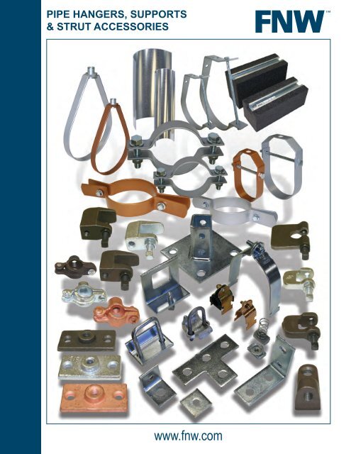
PIPE HANGERS, SUPPORTS<br />
& STRUT ACCESSORIES<br />
www.fnw.com
An FNW fyi<br />
Valve Automation<br />
Services Available<br />
FNW products are distributed through<br />
Wolseley North American operating<br />
companies. These companies<br />
contain an extensive array of Valve<br />
Automation Centers throughout the<br />
region and provide services directly,<br />
or through your local branch. Each<br />
facility offers a variety of valve<br />
automation expertise for sizing,<br />
designing, sourcing, assembling, and<br />
testing. This expertise is available<br />
at any time from the engineering<br />
office to the job site.<br />
To find out more about these services, contact your local<br />
Wolseley North American operating branch. For locations,<br />
visit www.ferguson.com or wolseleyinc.ca.
Index<br />
Type Description Figure Number Page<br />
Hangers........................ Hinged Split Ring.......................................................... 7001....................................... 6<br />
Standard Duty Adjustable Clevis................................... 7005....................................... 7<br />
Light Duty Adjustable Clevis.......................................... 7006....................................... 8<br />
Adjustable Clevis for Copper Tube................................ 7008....................................... 9<br />
Adjustable Swivel Ring.................................................. 7010..................................... 10<br />
Felt Lined Adjustable Swivel Ring................................. 7012..................................... 10<br />
Adjustable Swivel Ring for Copper Tube....................... 7015......................................11<br />
Adjustable “J”................................................................ 7025..................................... 12<br />
Clamps.......................... Medium Split Horizontal <strong>Pipe</strong> Clamp............................. 7020..................................... 13<br />
Riser Clamp.................................................................. 7022..................................... 14<br />
Riser Clamp for Copper Tube....................................... 7023..................................... 14<br />
Beam Clamps............... Steel C-Clamp............................................................... 7201..................................... 15<br />
Malleable Iron C-Clamp................................................ 7202..................................... 15<br />
Jr. Beam Clamp............................................................. 7203..................................... 15<br />
Wide Mouth Beam Clamp............................................. 7204..................................... 16<br />
Universal Beam Clamp................................................. 7806..................................... 16<br />
Right Angle Beam Clamp.............................................. 7868..................................... 16<br />
Window Type Strut to Beam Clamp.............................. 7801..................................... 16<br />
Strut to Beam Spreader Caps....................................... 7802..................................... 16<br />
Square U-Bolt Strut to Beam Clamp (short).................. 7803..................................... 17<br />
Square U-Bolt Strut to Beam Clamp (long)................... 7804..................................... 17<br />
Notched Type Strut to Beam Clamp.............................. 7805..................................... 17<br />
Beam Clamp Retaining Strap........................................ 7250..................................... 17<br />
Rollers........................... Roller Trolley 4-Bearing Assembly................................ 7865..................................... 17<br />
Brackets........................ Bracket Channel 1-5/8” Channel 2-HL.......................... 7811..................................... 18<br />
<strong>Pipe</strong> Support Systems.. 50# <strong>Pipe</strong> Support.......................................................... 7701..................................... 18<br />
150# <strong>Pipe</strong> Support........................................................ 7715..................................... 18<br />
300# <strong>Pipe</strong> Support........................................................ 7730..................................... 18<br />
Elevation Kit................................................................ELKITC.................................. 18<br />
Channel Nuts................ Long Spring Channel Nut.............................................. 7818..................................... 19<br />
No Spring Channel Nut................................................. 7819..................................... 19<br />
No Spring Channel Nut................................................. 7820..................................... 19<br />
Regular Spring Channel Nut......................................... 7821..................................... 19<br />
Short Spring Channel Nut............................................. 7822..................................... 19<br />
Top Spring Channel Nut................................................ 7824..................................... 19<br />
End Caps...................... PVC Channel End Cap (1-5/8”)..................................... 7830..................................... 20<br />
Channel End Cap (1-5/8”)............................................. 7831..................................... 20<br />
Angle Fittings................ No Twist 2-Hole Corner Angle Fitting............................ 7840..................................... 20<br />
2-Hole Corner Angle Fitting........................................... 7841..................................... 20<br />
Cross Corner Angle Fitting............................................ 7842..................................... 21<br />
3-Way Cross Corner Angle Fitting................................. 7843..................................... 21<br />
7-Hole Gusset Corner Angle Fitting.............................. 7844..................................... 21<br />
2-Hole Open 45° Corner Angle Fitting........................... 7845..................................... 21<br />
2-Hole Closed 45° Corner Angle Fitting........................ 7846..................................... 21<br />
4-Hole Open 45° Corner Angle Fitting........................... 7847..................................... 22<br />
2-Hole Angle Brace....................................................... 7848..................................... 22<br />
Flat Fittings................... Square Washer Flat Fitting............................................ 7835..................................... 22<br />
Notched Square Washer Flat Fitting............................. 7836..................................... 22<br />
Splice Plate Flat Fitting................................................. 7837..................................... 23<br />
3-Hole Corner Plate Flat Fitting..................................... 7838..................................... 23<br />
4-Hole Tee Plate Flat Fitting.......................................... 7839..................................... 23<br />
Post Base...................... Single Channel 2-Hole Base......................................... 7850..................................... 24<br />
Single Channel 2-Hole Flush Base............................... 7851..................................... 24<br />
Single Channel 4-Hole Standard................................... 7852..................................... 24<br />
Single Channel 4-Hole Base (tall)................................. 7853..................................... 24<br />
Single Channel 4-Hole Base (short).............................. 7855..................................... 24<br />
Strut Clamps................. Cushioned <strong>Pipe</strong> Strut Clamp......................................... 7815..................................... 25<br />
Cushioned Tubing Strut Clamp..................................... 7816..................................... 25<br />
Copper Tubing Strut Clamp........................................... 7870..................................... 26<br />
EMT Strut Clamp........................................................... 7871..................................... 26<br />
O.D. Strut Clamp........................................................... 7872..................................... 27<br />
Rigid Strut Clamp.......................................................... 7873..................................... 28<br />
Universal Strut Clamp................................................... 7874..................................... 28<br />
<strong>Pipe</strong> Wrap..................................................................... 7862..................................... 29<br />
Attachments.................. Beam Connector........................................................... 7501..................................... 30<br />
Ceiling Flange............................................................... 7502..................................... 30<br />
Conduit/<strong>Pipe</strong> Clamps.... Rigid/EMT Clamp.......................................................... 7310..................................... 30<br />
Copper <strong>Pipe</strong> Clamp....................................................... 7311..................................... 30<br />
Shields.......................... Insulation Protection Shields......................................... 7750..................................... 31<br />
Insulation Protection Shields (Domestic)...................... 7751..................................... 31<br />
Light Duty Insulation Protection Shields........................ 7753..................................... 31
Material Specifications<br />
Malleable Iron................................................................................................................ ASTM A47 Grade 32510<br />
Carbon Steel.............................................................................................................................ASTM A283 Gr. C<br />
Carbon Steel.............................................................................................................. ASTM A1011-00 SS GR 33<br />
Carbon Steel.............................................................................................................. ASTM A1011-00CS Type B<br />
304 Stainless Steel..........................................................................................................ASTM A240 (Type 304)<br />
Approvals & Standards<br />
Where indicated, FNW hanger products have the following approvals or are made to the following standards:<br />
MSS SP-58<br />
MSS SP-69<br />
WW-H-171<br />
NFPA 13<br />
UL Category VXFT/VXFT7 (UL 203 / ULC/ORD-C203)<br />
FM Class 1951<br />
Epoxy plating is tested according to:<br />
ASTM B117-03 (Epoxy Plating Test)<br />
ASTM D 3359-08 (Epoxy Plating Test)<br />
ASTM D 3363-05 (Epoxy Plating Test)<br />
Bolt and nut hardware dimensions for epoxy plated products per:<br />
ASME B.18.2.1 (Bolt)<br />
ASME B.18.2.2 (Nut)<br />
Finishes<br />
P....... Plain<br />
No finish applied<br />
Z....... Electroplated Zinc (Electro-Galvanized)<br />
Electroplating deposits zinc on the surface of the steel by electrolysis from a bath of zinc salts. This coating<br />
is recommended for relatively dry indoor use. This is the standard coating for most FNW <strong>strut</strong> accessory<br />
products. The thickness of zinc applied in this method is between 0.2 mils to 0.5 mils [5.1 μm to 12.7 μm]<br />
and meet ASTM B633 SC3 Type I.<br />
or<br />
Hot Dip Galvanized After Fabrication<br />
The steel is zinc coated by hot dipping the fabricated product. The product is dipped in molten zinc and<br />
is completely covered on all surfaces. This coating is generally recommended for outdoor use. The zinc<br />
coating thickness is typically 2.6 mils [66.0 μm ] or 1.5 oz. per square foot [0.46 kg per square meter] per<br />
side.<br />
Y....... Yellow Zinc Dichromate<br />
A 0.5 mil [12.7 μm] electro-galvanized zinc plating meeting ASTM B633 SC3 Type I is applied to the surface<br />
of the metal. Yellow Dichromate is applied over the zinc. This results in a yellowish-gold appearance and<br />
acts as a nonporous barrier sealant that is corrosion resistant and can be painted.<br />
C...... Copper Zinc Dichromate<br />
A 0.5 mil [12.7 μm] electro-galvanized zinc plating meeting ASTM B633 SC3 Type I is applied to the<br />
surface of the metal. Copper Zinc Dichromate is applied over the zinc. This results in a copper colored<br />
appearance and acts as a nonporous barrier sealant that does not react adversely with copper pipe or<br />
tubing.<br />
or<br />
Copper (Electrolytic)<br />
Electro-copper plated<br />
G...... Green E-Coat<br />
An 8-step electro-deposition epoxy coating. Following a thorough cleaning and phosphate rinse the epoxy<br />
is applied by immersing the part in liquid epoxy to ensure coverage in crevices and difficult areas. It is<br />
then baked on creating a 0.7 to 0.9 mil [18 – 23 μm] thick coating. This process negates drips and sags<br />
and produces a coating that withstands 1000 hours or more in a salt spray test. This coating is also an<br />
excellent base should the part need to be painted or powder coated before or after installation.<br />
S....... Stainless Steel<br />
Product made in 304 Stainless Steel - ASTM A240 (Type 304)<br />
EP.... Epoxy Plated (Zinc Colored)<br />
A highly durable and corrosion resistant coating system. See page 5 for details.<br />
EC.... Epoxy Plated (Copper Colored)<br />
A highly durable and corrosion resistant coating system. See page 5 for details.<br />
4 Phone: 503-287-8383 ~ Fax: 503-281-9677 ~ www.FNW.com
Epoxy Plated Finish<br />
FNW EP and EC designated <strong>hangers</strong> and clamps come standard with epoxy plating that uses a more<br />
environmentally friendly method than epoxy coatings that use phosphates and heavy metals. The eight step<br />
process results in a superior coating that both enhances corrosion resistance and appearance.<br />
Load<br />
Unload<br />
Water Clean Degrease Water Clean Bonderite© Water Clean Pre-Heat Powder Coating Curing<br />
Eight Step Epoxy Plating Process<br />
1. Water Clean - Initial cleaning after forming.<br />
2. Degrease - An alkaline solution to removes oils, lubrication grease, soil, and metal oxides.<br />
3. Water Clean - Removes alkaline solution.<br />
4. Bonderite® - Surface pretreatment using Bonderite® NT-1 (see below).<br />
5. Water Clean - Post-vitrification cleaning.<br />
6. Pre-Heat - Preheating prior to powder coating.<br />
7. Powder Coating - Epoxy is applied to minimum thickness of 0.05mm.<br />
8. Curing - Heated to a temperature of 392°F (200°C).<br />
About Bonderite© NT-1<br />
Bonderite ® Nanoparticles<br />
Iron Phosphate<br />
Bare Cold-Rolled Steel<br />
Bonderite® NT-1 is a nano-ceramic vitrification surface<br />
pretreatment that creates a cohesive, inorganic, very dense<br />
layer for outstanding corrosion protection that is superior to<br />
iron phosphating. Specifically formulated for use on metal<br />
surfaces like steel, it is absolutely uniform and is free of<br />
any phosphates or toxic heavy metals and does not require<br />
passivation. The nanotechnology also produces a smooth<br />
finish.<br />
0 1 µm<br />
0 1 µm<br />
Bonderite® and NT-1 are trademarks and/or registered trademarks of Henkel and its<br />
affiliates’. 0<br />
1 µm<br />
Superior Corrosion Resistance<br />
FNW <strong>hangers</strong> and clamps with epoxy plating are tested<br />
in a 20% salt spray solution that exceeds ASTM B 117-03<br />
salt solution requirements by a factor of 4.<br />
After 240 hours in a salt spray (fog) apparatus, the<br />
FNW hanger with epoxy plating showed little to no signs<br />
of corrosion or pitting and the finish was still smooth.<br />
Compare FNW’s to a typical electro-zinc plated hanger<br />
that shows significant corrosion and pitting after the same<br />
test. It is easy to see that FNW’s epoxy plating, offered as<br />
standard, is the superior finish.<br />
FNW epoxy plated<br />
hanger after 240<br />
hour salt spray test<br />
at 20% solution<br />
No Corrosion and<br />
Still Smooth<br />
Typical electro-zinc<br />
plated hanger after<br />
240 hour salt spray<br />
test at 20% solution<br />
Corrosion and Very<br />
Pitted<br />
Phone: 503-287-8383 ~ Fax: 503-281-9677 ~ www.FNW.com<br />
5
Hangers<br />
FIGURE 7001 - Hinged Split Ring<br />
Finish: Plain, Zinc, or Copper<br />
MSS SP-58, type 12<br />
Material: Malleable Iron, ASTM A47 Grade 32510<br />
A - Rod size (hanger rod and nuts not included)<br />
B - Center of pipe to top of hanger<br />
C - Width of hanger<br />
in.<br />
<strong>Pipe</strong> Size<br />
mm<br />
A<br />
(Rod Size)<br />
Plain &<br />
Zinc<br />
B (in.) <strong>Pipe</strong> Size C (in.) Max. Load Weights (oz.)<br />
Copper in. mm<br />
3/8 17.2 3/8”-16 0.66 0.66 3/8 17.2 2.06 1.78 180 1.66 1.34<br />
1/2 21.3 3/8”-16 0.75 0.75 1/2 21.3 2.22 1.97 180 1.76 1.62<br />
3/4 26.6 3/8”-16 0.84 0.84 3/4 26.6 2.50 2.25 180 2.08 1.80<br />
1 33.4 3/8”-16 0.97 0.97 1 33.4 2.75 2.44 180 2.36 2.08<br />
1-1/4 42.1 3/8”-16 1.16 1.13 1-1/4 42.1 3.22 2.78 180 3.10 2.40<br />
1-1/2 48.2 3/8”-16 1.28 1.25 1-1/2 48.2 3.44 3.06 180 3.46 2.82<br />
2 60.3 3/8”-16 1.53 1.47 2 60.3 3.94 3.53 180 4.41 3.77<br />
2-1/2 73.0 1/2”-13 1.94 1.88 2-1/2 73.0 4.75 4.44 300 7.65 6.81<br />
3 88.9 1/2”-13 2.56 2.16 3 88.9 5.38 4.94 300 9.17 7.51<br />
4 114.3 1/2”-13 2.75 2.63 4 114.3 6.41 5.94 300 10.58 9.28<br />
<strong>Pipe</strong> Size<br />
Catalog Number<br />
Plain &<br />
Zinc<br />
in. mm Plain Zinc Copper<br />
3/8 17.2 FNW7001PC FNW7001ZC FNW7001CC<br />
1/2 21.3 FNW7001PD FNW7001ZD FNW7001CD<br />
3/4 26.6 FNW7001PF FNW7001ZF FNW7001CF<br />
1 33.4 FNW7001PG FNW7001ZG FNW7001CG<br />
1-1/4 42.1 FNW7001PH FNW7001ZH FNW7001CH<br />
1-1/2 48.2 FNW7001PJ FNW7001ZJ FNW7001CJ<br />
2 60.3 FNW7001PK FNW7001ZK FNW7001CK<br />
2-1/2 73.0 FNW7001PL FNW7001ZL FNW7001CL<br />
3 88.9 FNW7001PM FNW7001ZM FNW7001CM<br />
4 114.3 FNW7001PP FNW7001ZP FNW7001CP<br />
Copper<br />
Lbs.<br />
Plain &<br />
Zinc<br />
Copper<br />
6 Phone: 503-287-8383 ~ Fax: 503-281-9677 ~ www.FNW.com
Hangers<br />
FIGURE 7005 - Standard Duty Adjustable Clevis Hangers<br />
UL/FM Approved - Sizes 2-1/2” to 8”<br />
Finish: Epoxy Plated<br />
Color: Zinc<br />
MSS SP-58, Type 1<br />
Federal Specification WW-H-171, Type 1<br />
A - Rod size (hanger rod and nuts not included)<br />
B - Bottom of pipe to top of hanger<br />
C - Center of pipe to top of hanger<br />
D - Rod take out (center of pipe to bottom of hanger<br />
rod)<br />
1/2” to 1-1/4”<br />
E - Minimum thread length of hanger rod<br />
F - Adjustment, top of cross bolt to bottom of hanger<br />
rod nut inside hanger 1-1/2” to 12”<br />
Catalog Number<br />
<strong>Pipe</strong> Size<br />
A<br />
B C D<br />
in. mm (Rod Size)<br />
in. mm in. mm in. mm<br />
FNW7005EP0050 1/2 21.3 3/8”-16 1-15/16 49.00 1-7/16 37.55 3/8 9.5<br />
FNW7005EP0075 3/4 26.6 3/8”-16 2-1/4 57.40 1-3/4 43.25 5/8 15.3<br />
FNW7005EP0100 1 33.4 3/8”-16 2-11/16 68.00 2 50.50 7/8 22.5<br />
FNW7005EP0125 1-1/4 42.1 3/8”-16 3-1/4 82.00 2-3/8 59.90 1-1/4 31.9<br />
FNW7005EP0150 1-1/2 48.2 3/8”-16 3-7/8 98.00 2-7/8 72.85 1-3/4 44.9<br />
FNW7005EP0200 2 60.3 3/8”-16 4-5/16 109.00 3-1/16 77.85 1-15/16 49.4<br />
FNW7005EP0250 2-1/2 73.0 1/2”-13 5-1/8 130.20 3-5/8 92.65 2-5/16 57.9<br />
FNW7005EP0300 3 88.9 1/2”-13 5-15/16 150.10 4-1/8 104.40 2-3/4 69.2<br />
FNW7005EP0350 3-1/2 101.6 1/2”-13 6-1/2 165.50 4-7/16 113.45 3-1/16 78.2<br />
FNW7005EP0400 4 114.3 5/8”-11 7-7/16 189.00 5-1/8 130.35 3-11/16 93.6<br />
FNW7005EP0500 5 141.3 5/8”-11 9-1/4 233.80 6-3/8 161.40 4-5/8 117.0<br />
FNW7005EP0600 6 168.2 3/4”-10 10-1/2 267.30 7-1/8 181.15 5-5/16 134.8<br />
FNW7005EP0800 8 219.1 3/4”-10 12-15/16 328.40 8-1/2 216.35 6-1/2 164.7<br />
FNW7005EP1000 10 273.1 7/8”-9 15-1/2 394.00 10 254.45 7-5/8 194.2<br />
FNW7005EP1200 12 323.9 7/8”-9 18-5/8 473.10 12-1/8 307.90 9-3/4 247.6<br />
Catalog Number<br />
<strong>Pipe</strong> Size E F<br />
Design Load Weight<br />
Bolt Size<br />
in. mm in. mm in. mm Lbs. kN Lbs.<br />
FNW7005EP0050 1/2 21.3 2-1/2 63.5 7/16 11.1 1/4-20UNC 610 2.71 0.15<br />
FNW7005EP0075 3/4 26.6 2-1/2 63.5 1/2 12.7 1/4-20UNC 610 2.71 0.17<br />
FNW7005EP0100 1 33.4 2-1/2 63.5 5/8 15.9 1/4-20UNC 610 2.71 0.20<br />
FNW7005EP0125 1-1/4 42.1 2-1/2 63.5 7/8 22.2 1/4-20UNC 610 2.71 0.29<br />
FNW7005EP0150 1-1/2 48.2 2-1/2 63.5 1-3/16 30.2 1/4-20UNC 610 2.71 0.32<br />
FNW7005EP0200 2 60.3 2-1/2 63.5 1-5/8 41.3 1/4-20UNC 610 2.71 0.39<br />
FNW7005EP0250 2-1/2 73.0 2-1/2 63.5 2 50.8 5/16-18UNC 1130 5.02 0.67<br />
FNW7005EP0300 3 88.9 2-1/2 63.5 2 50.8 5/16-18UNC 1130 5.02 0.83<br />
FNW7005EP0350 3-1/2 101.6 2-1/2 63.5 2 50.8 5/16-18UNC 1130 5.02 0.91<br />
FNW7005EP0400 4 114.3 2-1/2 63.5 2 50.8 5/16-18UNC 1430 6.36 1.25<br />
FNW7005EP0500 5 141.3 2-1/2 63.5 2 50.8 3/8-16UNC 1430 6.36 2.03<br />
FNW7005EP0600 6 168.2 3 76.2 2 50.8 3/8-16UNC 1940 8.62 3.56<br />
FNW7005EP0800 8 219.1 3-1/2 88.9 2-5/16 58.7 5/8-11UNC 2000 8.89 4.89<br />
FNW7005EP1000 10 273.1 3-1/2 88.9 2-5/16 58.7 3/4-10UNC 3600 16.00 8.64<br />
FNW7005EP1200 12” 323.9 3-1/2” 88.9 2-5/16 66.7 3/4-10UNC 3800 16.89 10.18<br />
Phone: 503-287-8383 ~ Fax: 503-281-9677 ~ www.FNW.com<br />
7
Hangers<br />
FIGURE 7006 - Light Duty Adjustable Clevis Hangers<br />
UL Approved - Sizes 3/4” to 4”<br />
Finish: Epoxy Plated<br />
Color: Zinc<br />
MSS SP-58, Type 1<br />
Federal Specification WW-H-171, Type 1<br />
A - Rod size (hanger rod and nuts not included)<br />
B - Bottom of pipe to top of hanger<br />
C - Center of pipe to top of hanger<br />
D - Rod take out (center of pipe to bottom of hanger 1/2” to 1-1/4”<br />
rod)<br />
E - Minimum thread length of hanger rod<br />
F - Adjustment, top of cross bolt to bottom of hanger<br />
rod nut inside hanger 1-1/2” to 4”<br />
Catalog Number<br />
<strong>Pipe</strong> Size<br />
A<br />
B C D<br />
in. mm (Rod Size)<br />
in. mm in. mm in. mm<br />
FNW7006EP0050 1/2 21.3 3/8”-16 2 51.20 1-1/2 39.75 1/2 13.05<br />
FNW7006EP0075 3/4 26.6 3/8”-16 2-7/16 61.60 1-7/8 47.45 3/4 20.75<br />
FNW7006EP0100 1 33.4 3/8”-16 2-11/16 68.52 2 51.02 15/16 24.32<br />
FNW7006EP0125 1-1/4 42.1 3/8”-16 3-3/16 83.20 2-3/8 61.10 1-5/16 34.10<br />
FNW7006EP0150 1-1/2 48.2 3/8”-16 3-7/8 98.90 2-7/8 73.75 1-7/8 46.75<br />
FNW7006EP0200 2 60.3 3/8”-16 4-3/8 111.90 3-3/16 80.75 1-15/16 48.75<br />
FNW7006EP0250 2-1/2 73.0 1/2”-13 5-3/16 131.20 3-11/16 93.70 2-5/16 58.80<br />
FNW7006EP0300 3 88.9 1/2”-13 5-7/8 149.40 4-1/16 103.70 2-3/4 68.80<br />
FNW7006EP0400 4 114.3 5/8”-11 7-5/8 194.00 5-5/16 135.35 3-15/16 99.45<br />
Catalog Number<br />
<strong>Pipe</strong> Size E F<br />
Design Load Weight<br />
Bolt Size<br />
in. mm in. mm in. mm Lbs. kN Lbs.<br />
FNW7006EP0050 1/2 21.3 2-1/2 63.5 7/16 11.1 1/4-20UNC 150 0.67 0.10<br />
FNW7006EP0075 3/4 26.6 2-1/2 63.5 1/2 12.7 1/4-20UNC 150 0.67 0.12<br />
FNW7006EP0100 1 33.4 2-1/2 63.5 5/8 15.9 1/4-20UNC 250 1.11 0.13<br />
FNW7006EP0125 1-1/4 42.1 2-1/2 63.5 7/8 22.2 1/4-20UNC 250 1.11 0.21<br />
FNW7006EP0150 1-1/2 48.2 2-1/2 63.5 1-3/16 30.2 1/4-20UNC 250 1.11 0.23<br />
FNW7006EP0200 2 60.3 2-1/2 63.5 1-5/8 41.3 1/4-20UNC 250 1.11 0.33<br />
FNW7006EP0250 2-1/2 73.0 2-1/2 63.5 2 50.8 3/8-16UNC 350 1.56 0.45<br />
FNW7006EP0300 3 88.9 2-1/2 63.5 2 50.8 3/8-16UNC 350 1.56 0.51<br />
FNW7006EP0400 4 114.3 2-1/2 63.5 2 50.8 3/8-16UNC 400 1.78 0.84<br />
8 Phone: 503-287-8383 ~ Fax: 503-281-9677 ~ www.FNW.com
Hangers<br />
FIGURE 7008 - Adjustable Clevis Hangers for Copper Tube<br />
Finish: Epoxy Plated<br />
Color: Copper<br />
MSS SP-58, Type 1<br />
Federal Specification WW-H-171, Type 1<br />
A - Rod size (hanger rod and nuts not included)<br />
B - Bottom of pipe to top of hanger<br />
C - Center of pipe to top of hanger<br />
D - Rod take out (center of pipe to bottom of hanger<br />
rod)<br />
1/2” to 1-1/2”<br />
E - Minimum thread length of hanger rod<br />
F - Adjustment, top of cross bolt to bottom of hanger<br />
rod nut inside hanger 2” to 6”<br />
Catalog Number<br />
<strong>Pipe</strong> Size<br />
A<br />
B C D<br />
in. mm (Rod size) in. mm in. mm in. mm<br />
FNW7008EC0050 1/2 15.9 3/8”-16 1-3/4 45.00 1-7/16 36.20 3/8 9.20<br />
FNW7008EC0075 3/4 22.2 3/8”-16 2 51.40 1-1/2 39.40 1/2 12.40<br />
FNW7008EC0100 1 28.6 3/8”-16 2-7/16 61.70 1-7/8 46.55 3/4 19.55<br />
FNW7008EC0125 1-1/4 34.9 3/8”-16 2-3/4 71.10 2-1/16 52.55 1 25.55<br />
FNW7008EC0150 1-1/2 41.3 3/8”-16 3-3/16 82.00 2-3/8 60.30 1-1/8 27.80<br />
FNW7008EC0200 2 54.1 3/8”-16 4-1/16 102.70 2-15/16 74.65 1-5/8 42.15<br />
FNW7008EC0250 2-1/2 66.7 1/2”-13 5-3/16 131.37 3-7/8 96.77 2-5/16 57.52<br />
FNW7008EC0300 3 79.4 1/2”-13 5-5/8 142.47 4 101.52 2-7/16 62.27<br />
FNW7008EC0400 4 104.8 1/2”-13 6-1/2 166.27 4-7/16 112.37 2-7/8 72.62<br />
FNW7008EC0500 5 130.2 1/2”-13 9-1/8 231.17 6-1/2 164.42 4-1/2 116.02<br />
FNW7008EC0600 6 155.6 5/8”-11 11-1/16 281.07 7-15/16 201.32 6 152.92<br />
Catalog Number<br />
<strong>Pipe</strong> Size E F<br />
Design Load Weight<br />
Bolt Size<br />
in. mm in. mm in. mm Lbs. kN Lbs.<br />
FNW7008EC0050 1/2 15.9 2-1/2 63.5 7/16 11.1 1/4-20UNC 150 0.67 0.09<br />
FNW7008EC0075 3/4 22.2 2-1/2 63.5 1/2 12.7 1/4-20UNC 250 1.11 0.10<br />
FNW7008EC0100 1 28.6 2-1/2 63.5 5/8 15.9 1/4-20UNC 250 1.11 0.13<br />
FNW7008EC0125 1-1/4 34.9 2-1/2 63.5 7/8 22.2 1/4-20UNC 250 1.11 0.15<br />
FNW7008EC0150 1-1/2 41.3 2-1/2 63.5 1-3/16 30.2 1/4-20UNC 250 1.11 0.18<br />
FNW7008EC0200 2 54.1 2-1/2 63.5 1-5/8 41.3 1/4-20UNC 250 1.11 0.21<br />
FNW7008EC0250 2-1/2 66.7 2-1/2 63.5 2 50.8 5/16-18UNC 350 1.56 0.51<br />
FNW7008EC0300 3 79.4 2-1/2 63.5 2 50.8 5/16-18UNC 350 1.56 0.57<br />
FNW7008EC0400 4 104.8 2-1/2 63.5 2 50.8 5/16-18UNC 400 1.78 0.70<br />
FNW7008EC0500 5 130.2 2-1/2 63.5 2 50.8 3/8-16UNC 550 2.45 1.50<br />
FNW7008EC0600 6 155.6 3” 76.2 2 50.8 3/8-16UNC 500 2.23 1.80<br />
Phone: 503-287-8383 ~ Fax: 503-281-9677 ~ www.FNW.com<br />
9
Hangers<br />
FIGURE 7010 - Adjustable Swivel Ring Hangers<br />
UL Approved - Sizes 1/2” to 8”<br />
FM Approved - Sizes 3/4” to 8”<br />
Finish: Epoxy Plated<br />
Color: Zinc<br />
MSS SP-58, Type 10<br />
Federal Specification WW-H-171, Type 10<br />
NFPA 13<br />
A - Rod size (hanger rod not included)<br />
B - Center of pipe to top of knured hanger rod nut<br />
C - Rod take out (center of pipe to bottom of hanger<br />
rod<br />
D - Top of pipe to bottom of hanger rod nut<br />
Catalog Number<br />
<strong>Pipe</strong> Size<br />
A<br />
B C D Design Load Weight<br />
in. mm (Rod size) in. mm in. mm in. mm Lbs. kN Lbs.<br />
FNW7010EP0050 1/2 21.3 3/8-16UNC 2-7/32 56.36 25/32 19.8 7/8 22.2 300 1.33 0.09<br />
FNW7010EP0075 3/4 26.6 3/8-16UNC 2-7/16 61.91 1-1/32 26.2 1-3/32 27.8 300 1.33 0.09<br />
FNW7010EP0100 1 33.4 3/8-16UNC 2-5/8 66.68 1-7/32 31.0 1-3/16 30.2 300 1.33 0.10<br />
FNW7010EP0125 1-1/4 42.1 3/8-16UNC 2-25/32 70.64 1-3/8 34.9 1-5/32 29.4 300 1.33 0.11<br />
FNW7010EP0150 1-1/2 48.2 3/8-16UNC 2-7/8 73.03 1-7/16 36.5 1-3/32 27.8 300 1.33 0.12<br />
FNW7010EP0200 2 60.3 3/8-16UNC 3-1/32 76.99 1-19/32 40.5 1-1/32 26.2 300 1.33 0.13<br />
FNW7010EP0250 2-1/2 73 3/8-16UNC 3-31/32 100.81 2-9/16 65.1 1-23/32 43.7 525 4.45 0.29<br />
FNW7010EP0300 3 88.9 3/8-16UNC 4-15/32 113.51 3-1/16 77.8 1-15/16 49.2 525 4.45 0.33<br />
FNW7010EP0350 3-1/2 101.6 3/8-16UNC 4-15/16 125.41 3-17/32 89.7 2-1/8 54.0 585 4.45 0.37<br />
FNW7010EP0400 4 114.3 3/8-16UNC 5-9/32 134.14 3-27/32 97.6 2-3/16 55.6 650 4.89 0.39<br />
FNW7010EP0500 5 141.3 1/2-13UNC 5-31/32 151.61 4-7/16 112.7 2-1/4 57.2 1000 4.89 0.53<br />
FNW7010EP0600 6 168.2 1/2-13UNC 7 177.80 5-1/2 139.7 2-3/4 69.9 1000 5.56 0.72<br />
FNW7010EP0800 8 219 1/2-13UNC 7-31/32 202.41 6-7/16 163.5 2-23/32 69.1 1000 5.56 1.04<br />
FIGURE 7012 - Felt Lined Adjustable Swivel Ring Hangers<br />
UL Approved - Sizes 1/2” to 4”<br />
FM Approved - Sizes 3/4” to 4”<br />
NFPA Rod - Sizes 1/2” to 4” *<br />
Finish: Epoxy Plated<br />
Color: Zinc<br />
MSS SP-58, Type 10<br />
Federal Specification WW-H-171, Type 10<br />
NFPA 13<br />
* Note: For 2-1/2” to 4” <strong>hangers</strong> with<br />
NFPA rod sizes,use figure number 7012N<br />
A - Rod size (hanger rod not included)<br />
B - Center of pipe to top of knured hanger rod nut<br />
C - Rod take out (center of pipe to bottom of hanger<br />
rod<br />
D - Top of pipe to bottom of hanger rod nut<br />
Catalog Number<br />
<strong>Pipe</strong> Size<br />
A<br />
B C D Design Load Weight<br />
in. mm (Rod size) in. mm in. mm in. mm Lbs. kN Lbs.<br />
FNW7012EP0050 1/2 21.3 3/8-16UNC 2-7/32 56.36 25/32 19.8 7/8 22.2 300 1.33 0.089<br />
FNW7012EP0075 3/4 26.6 3/8-16UNC 2-7/16 61.91 1-1/32 26.2 1-3/32 27.8 300 1.33 0.095<br />
FNW7012EP0100 1 33.4 3/8-16UNC 2-5/8 66.68 1-7/32 31.0 1-3/16 30.2 300 1.33 0.100<br />
FNW7012EP0125 1-1/4 42.1 3/8-16UNC 2-25/32 70.64 1-3/8 34.9 1-5/32 29.4 300 1.33 0.112<br />
FNW7012EP0150 1-1/2 48.2 3/8-16UNC 2-7/8 73.03 1-7/16 36.5 1-3/32 27.8 300 1.33 0.121<br />
FNW7012EP0200 2 60.3 3/8-16UNC 3-1/32 76.99 1-19/32 40.5 1-1/32 26.2 300 1.33 0.130<br />
FNW7012EP0250 2-1/2 73 1/2-13UNC 3-31/32 100.81 2-9/16 65.1 1-23/32 43.7 1000 2.34 0.323<br />
FNW7012EP0300 3 88.9 1/2-13UNC 4-15/32 113.51 3-1/16 77.8 1-15/16 49.2 1000 2.34 0.359<br />
FNW7012EP0400 4 114.3 5/8-11UNC 5-9/32 134.14 3-27/32 97.6 2-3/16 55.6 1100 2.89 0.474<br />
FNW7012NEP0250* 2-1/2 73 3/8-16UNC 3-31/32 100.81 2-9/16 65.1 1-23/32 43.7 525 2.34 0.323<br />
FNW7012NEP0300* 3 88.9 3/8-16UNC 4-15/32 113.51 3-1/16 77.8 1-15/16 49.2 525 2.34 0.359<br />
FNW7012NEP0400* 4 114.3 3/8-16UNC 5-9/32 134.14 3-27/32 97.6 2-3/16 55.6 650 2.89 0.474<br />
10 Phone: 503-287-8383 ~ Fax: 503-281-9677 ~ www.FNW.com
Hangers<br />
FIGURE 7015 - Adjustable Swivel Ring Hangers for Copper Tube<br />
Finish: Epoxy Plated<br />
Color: Copper<br />
MSS SP-58, Type 10<br />
Federal Specification WW-H-171, Type 10<br />
A - Rod size (hanger rod not included)<br />
B - Center of pipe to top of knured hanger rod nut<br />
C - Rod take out (center of pipe to bottom of hanger<br />
rod<br />
D - Top of pipe to bottom of hanger rod nut<br />
Catalog Number<br />
<strong>Pipe</strong> Size<br />
A<br />
B C D<br />
in. mm (Rod Size)<br />
in. mm in. mm in. mm<br />
FNW7015EC0050 1/2 16.00 3/8-16UNC 2-1/4 57.2 13/16 20.6 15/16 23.8<br />
FNW7015EC0075 3/4 22.35 3/8-16UNC 2-1/2 63.5 1-3/32 27.8 1 3/16 30.2<br />
FNW7015EC0100 1 28.70 3/8-16UNC 2-17/32 64.3 1-1/8 28.6 1 5/32 29.4<br />
FNW7015EC0125 1-1/4 35.05 3/8-16UNC 2-1/2 63.5 1-3/32 27.8 31/32 24.6<br />
FNW7015EC0150 1-1/2 41.40 3/8-16UNC 2-27/32 72.2 1-7/16 36.5 1 3/16 30.2<br />
FNW7015EC0200 2 54.10 3/8-16UNC 2-27/32 72.2 1-13/32 35.7 29/32 23.0<br />
FNW7015EC0250 2-1/2 66.68 3/8-16UNC 3 76.2 1-19/32 40.5 27/32 21.4<br />
FNW7015EC0300 3 79.38 1/2-13UNC 3-15/16 100.0 2-13/32 61.1 1-13/32 35.7<br />
FNW7015EC0400 4 104.78 1/2-13UNC 4-3/4 120.7 3-7/32 81.8 1-3/4 44.5<br />
FNW7015EC0500 5 130.18 5/8-11UNC 5-25/32 146.8 4-3/16 106.4 2-1/4 57.2<br />
FNW7015EC0600 6 155.58 5/8-11UNC 6-3/16 157.2 4-5/8 117.5 2-5/32 54.8<br />
Catalog Number<br />
<strong>Pipe</strong> Size Design Load Weight<br />
in. mm Lbs. kN Lbs.<br />
FNW7015EC0050 1/2 16.00 300 1.33 0.09<br />
FNW7015EC0075 3/4 22.35 300 1.33 0.10<br />
FNW7015EC0100 1 28.70 300 1.33 0.10<br />
FNW7015EC0125 1-1/4 35.05 300 1.33 0.10<br />
FNW7015EC0150 1-1/2 41.40 300 1.33 0.11<br />
FNW7015EC0200 2 54.10 300 1.33 0.11<br />
FNW7015EC0250 2-1/2 66.68 525 2.34 0.13<br />
FNW7015EC0300 3 79.38 525 2.34 0.31<br />
FNW7015EC0400 4 104.78 650 2.89 0.38<br />
FNW7015EC0500 5 130.18 1000 4.45 0.53<br />
FNW7015EC0600 6 155.58 1000 4.45 0.78<br />
Phone: 503-287-8383 ~ Fax: 503-281-9677 ~ www.FNW.com<br />
11
Hangers<br />
FIGURE 7025 - Adjustable “J” Hangers<br />
Finish: Epoxy Plated<br />
Color: Zinc<br />
MSS SP-58, Type 5<br />
A - Rod size (hanger rod and nuts not included)<br />
B - Center of pipe to top of hanger<br />
C - Rod take out (center of pipe to bottom of hanger rod<br />
Catalog Number<br />
<strong>Pipe</strong> Size<br />
A<br />
B<br />
C<br />
Bolt Size<br />
in. mm (Rod Size) in. mm in. mm<br />
FNW7025EP0050 1/2” 21.3 1/4-20UNC x 2-1/4 3/8-16UNC 1-27/32 46.8 7/8 22.2<br />
FNW7025EP0075 3/4” 26.7 1/4-20UNC x 2-1/4 3/8-16UNC 2-1/4 57.2 7/8 22.2<br />
FNW7025EP0100 1” 33.4 1/4-20UNC x 2-1/2 3/8-16UNC 2-7/32 56.4 31/32 24.6<br />
FNW7025EP0125 1-1/4” 42.2 1/4-20UNC x 2-3/4 3/8-16UNC 2-19/32 65.9 31/32 24.6<br />
FNW7025EP0150 1-1/2” 48.3 1/4-20UNC x 3 3/8-16UNC 2-7/16 61.9 1-7/32 31.0<br />
FNW7025EP0200 2” 60.3 1/4-20UNC x 3-1/2 3/8-16UNC 2-21/32 67.5 1-7/32 31.0<br />
FNW7025EP0250 2-1/2” 73.0 3/8-16UNC x 4-1/2 1/2-13UNC 3-1/16 77.8 1-31/32 50.0<br />
FNW7025EP0300 3” 88.9 3/8-16UNC x 5 1/2-13UNC 3-9/32 83.3 1-31/32 50.0<br />
FNW7025EP0400 4” 114.3 3/8-16UNC x 6-1/4 5/8-11UNC 3-25/32 96.0 1-31/32 50.0<br />
FNW7025EP0500 5” 141.3 3/8-16UNC x 8-1/4 5/8-11UNC 3 1/2 88.9 1-3/16 30.2<br />
FNW7025EP0600 6” 168.3 3/8-16UNC x 9-3/4 3/4-10UNC 4 5/16 109.5 1-9/16 39.7<br />
FNW7025EP0800 8” 219.1 3/8-16UNC x 11 3/4-10UNC 4 31/32 126.2 1-31/32 50.0<br />
Catalog Number<br />
<strong>Pipe</strong> Size D E Design Load Weight<br />
in. mm in. mm in. mm Lbs. kN Lbs.<br />
FNW7025EP0050 1/2” 21.3 1-1/16 27.0 13/32 10.3 400 1.78 0.14<br />
FNW7025EP0075 3/4” 26.7 1-15/32 37.3 13/32 10.3 400 1.78 0.16<br />
FNW7025EP0100 1” 33.4 1-7/16 36.5 13/32 10.3 400 1.78 0.18<br />
FNW7025EP0125 1-1/4” 42.2 1-13/16 46.0 13/32 10.3 400 1.78 0.21<br />
FNW7025EP0150 1-1/2” 48.3 1-21/32 42.1 13/32 10.3 400 1.78 0.21<br />
FNW7025EP0200 2” 60.3 1-7/8 47.6 13/32 10.3 400 1.78 0.23<br />
FNW7025EP0250 2-1/2” 73.0 2-9/32 57.9 9/16 14.3 800 3.56 0.40<br />
FNW7025EP0300 3” 88.9 2-1/2 63.5 9/16 14.3 800 3.56 0.47<br />
FNW7025EP0400 4” 114.3 3 76.2 9/16 14.3 800 3.56 0.73<br />
FNW7025EP0500 5” 141.3 2-17/32 63.9 9/16 14.3 800 3.56 1.15<br />
FNW7025EP0600 6” 168.3 3-11/32 84.5 9/16 14.3 1000 4.45 2.14<br />
FNW7025EP0800 8” 219.1 4 101.2 9/16 14.3 1200 5.34 2.71<br />
12 Phone: 503-287-8383 ~ Fax: 503-281-9677 ~ www.FNW.com
Clamps<br />
FIGURE 7020 - Medium Split Horizontal <strong>Pipe</strong> Clamps<br />
UL Approved - Sizes 3/4” to 8”<br />
Finish: Epoxy Plated<br />
Color: Zinc<br />
MSS SP-58, Type 4<br />
Federal Specification WW-H-171, Type 4<br />
A - Center of pipe to center of bolt<br />
B - Center of pipe to end of clamp<br />
Catalog Number<br />
<strong>Pipe</strong> Size<br />
A<br />
B<br />
Bolt Size<br />
in. mm in. mm in. mm<br />
FNW7020EP0050 1/2 21.3 5/16-18UNC 13/32 10.6 1-1/32 26.2<br />
FNW7020EP0075 3/4 26.7 5/16-18UNC 15/32 12.0 1-3/32 27.8<br />
FNW7020EP0100 1 33.4 5/16-18UNC 15/32 12.2 1-11/32 34.1<br />
FNW7020EP0125 1-1/4 42.2 5/16-18UNC 15/32 12.2 1-7/16 36.5<br />
FNW7020EP0150 1-1/2 48.3 5/16-18UNC 15/32 12.2 1-5/8 41.3<br />
FNW7020EP0200 2 60.3 1/2-13UNC 21/32 16.4 2-1/8 54.0<br />
FNW7020EP0250 2-1/2 73.0 1/2-13UNC 5/8 16.0 2-5/8 66.7<br />
FNW7020EP0300 3 88.9 1/2-13UNC 23/32 18.0 3-1/32 77.0<br />
FNW7020EP0350 3-1/2 101.6 1/2-13UNC 23/32 18.6 3-1/4 82.6<br />
FNW7020EP0400 4 114.3 5/8-11UNC 3/4 19.4 3-9/16 90.5<br />
FNW7020EP0500 5 141.3 5/8-11UNC 3/4 19.4 4-19/32 116.7<br />
FNW7020EP0600 6 168.3 3/4-10UNC 23/32 18.2 4-15/16 125.4<br />
FNW7020EP0800 8 219.1 3/4-10UNC 15/16 24.0 6-3/16 157.2<br />
FNW7020EP1000 10 273.1 7/8-9UNC 1-1/4 32.0 7-19/32 192.9<br />
FNW7020EP1200 12 323.9 7/8-9UNC 1-7/16 36.8 8-9/16 217.5<br />
Catalog Number<br />
<strong>Pipe</strong> Size C Design Load Weight<br />
in. mm in. mm Lbs. kN Lbs.<br />
FNW7020EP0050 1/2 21.3 1-17/32 38.9 500 2.2 0.33<br />
FNW7020EP0075 3/4 26.7 1-19/32 40.5 500 2.2 0.34<br />
FNW7020EP0100 1 33.4 1-7/8 47.6 500 2.2 0.40<br />
FNW7020EP0125 1-1/4 42.2 1-15/16 49.2 500 2.2 0.42<br />
FNW7020EP0150 1-1/2 48.3 2-1/8 54.0 800 3.6 0.46<br />
FNW7020EP0200 2 60.3 2-23/32 69.1 1040 4.6 0.90<br />
FNW7020EP0250 2-1/2 73.0 3-1/4 82.6 1040 4.6 1.05<br />
FNW7020EP0300 3 88.9 3-21/32 92.9 1040 4.6 1.18<br />
FNW7020EP0350 3-1/2 101.6 3-27/32 97.6 1040 4.6 1.25<br />
FNW7020EP0400 4 114.3 4-15/32 113.5 1040 4.6 1.91<br />
FNW7020EP0500 5 141.3 5-15/32 138.9 1040 4.6 2.29<br />
FNW7020EP0600 6 168.3 5-13/16 147.6 1615 7.2 5.30<br />
FNW7020EP0800 8 219.1 7-1/16 179.4 1615 7.2 6.36<br />
FNW7020EP1000 10 273.1 8-23/32 221.5 2400 10.7 13.53<br />
FNW7020EP1200 12 323.9 9-23/32 246.9 2400 10.7 14.93<br />
Phone: 503-287-8383 ~ Fax: 503-281-9677 ~ www.FNW.com<br />
13
Clamps<br />
FIGURE 7022 - Riser Clamps<br />
UL Approved - Sizes 1/2” to 8”<br />
Finish: Epoxy Plated<br />
Color: Zinc<br />
MSS SP-58, Type 8<br />
Federal Specification WW-H-171, Type 8<br />
Catalog Number<br />
<strong>Pipe</strong> Size<br />
L<br />
Design Load<br />
Torque Weight<br />
Bolt Size<br />
in. mm in. mm Lbs. kN Value<br />
Lbs.<br />
FNW7022EP0050 1/2 21.3 8-1/2 215.9 3/8-16UNC 220 0.98 25 ft.lbs 0.65<br />
FNW7022EP0075 3/4 26.6 9 228.5 3/8-16UNC 220 0.98 25 ft.lbs 0.71<br />
FNW7022EP0100 1 33.4 9-1/16 230 3/8-16UNC 220 0.98 25 ft.lbs 0.73<br />
FNW7022EP0125 1-1/4 42.1 9-1/2 241.3 3/8-16UNC 250 1.11 25 ft.lbs 0.77<br />
FNW7022EP0150 1-1/2 48.2 9-9/10 251.5 3/8-16UNC 250 1.11 25 ft.lbs 0.81<br />
FNW7022EP0200 2 60.3 10-3/10 261.6 3/8-16UNC 300 1.33 25 ft.lbs 1.44<br />
FNW7022EP0250 2-1/2 73 11-1/16 281 3/8-16UNC 400 1.78 25 ft.lbs 1.56<br />
FNW7022EP0300 3 88.9 11-3/4 298.5 3/8-16UNC 500 2.22 25 ft.lbs 1.79<br />
FNW7022EP0400 4 114.3 12-15/16 328.6 1/2-13UNC 750 3.33 55 ft.lbs 3.05<br />
FNW7022EP0500 5 141.3 14-1/4 362 1/2-13UNC 1500 6.67 55 ft.lbs 3.41<br />
FNW7022EP0600 6 168.2 15-1/2 393.7 1/2-13UNC 1600 7.11 55 ft.lbs 4.78<br />
FNW7022EP0800 8 219 18-1/4 463.5 5/8-11UNC 2500 11.12 80 ft.lbs 9.23<br />
FNW7022EP1000 10 273 20-1/10 510.5 5/8-11UNC 2500 11.12 80 ft.lbs 10.39<br />
FNW7022EP1200 12 323.8 22-3/8 568.3 5/8-11UNC 2700 12.01 80 ft.lbs 16.09<br />
FIGURE 7023 - Riser Clamps for Copper Tube<br />
Finish: Epoxy Plated<br />
Color: Copper<br />
MSS SP-58, Type 8<br />
Federal Specification WW-H-171, Type 8<br />
Catalog Number<br />
<strong>Pipe</strong> Size<br />
L<br />
Design Load<br />
Torque Weight<br />
Bolt size<br />
in. mm in. mm Lbs. kN Value<br />
Lbs.<br />
FNW7023EC0050 1/2 15.9 8-1/2 216.5 3/8-16UNC 75 0.33 25 ft.lbs 0.68<br />
FNW7023EC0075 3/4 22.2 9-1/4 235.5 3/8-16UNC 75 0.33 25 ft.lbs 0.75<br />
FNW7023EC0100 1 28.6 9-5/16 237.0 3/8-16UNC 120 0.53 25 ft.lbs 0.86<br />
FNW7023EC0125 1-1/4 34.9 9-1/2 241.0 3/8-16UNC 150 0.67 25 ft.lbs 1.16<br />
FNW7023EC0150 1-1/2 41.3 9-5/8 245.0 3/8-16UNC 150 0.67 25 ft.lbs 1.18<br />
FNW7023EC0200 2 54.1 10-7/16 265.0 3/8-16UNC 150 0.67 25 ft.lbs 1.30<br />
FNW7023EC0250 2-1/2 66.7 11-3/16 284.5 3/8-16UNC 300 1.34 25 ft.lbs 1.38<br />
FNW7023EC0300 3 79.4 12 304.0 3/8-16UNC 300 1.34 25 ft.lbs 1.49<br />
FNW7023EC0400 4 104.8 12-1/2 318.0 3/8-16UNC 300 1.34 25 ft.lbs 1.61<br />
FNW7023EC0600 6 155.6 15-1/8 385.0 1/2-13UNC 600 2.67 55 ft.lbs 5.27<br />
14 Phone: 503-287-8383 ~ Fax: 503-281-9677 ~ www.FNW.com
Beam Clamps<br />
Beam Clamps<br />
FIGURE 7201 - Steel Beam C-Clamp<br />
FIGURE 7203 - Jr. Beam Clamp<br />
Finish: Plain<br />
MSS SP-58, type 23<br />
Material: Steel, ASTM A283<br />
Hanger rod not included<br />
Catalog Number A B C D E<br />
FNW7201PC 2.13” 0.88” 2.38” 0.75” 0.25”<br />
Rod Size Finish Max. Load Wt. (0z.)<br />
3/8”-16 Plain 400 Lbs. 5.75<br />
FIGURE 7202 - MI Beam C-Clamp<br />
Finish: Plain or Zinc<br />
Per: MSS SP-58, type 23<br />
Material: Malleable Iron,<br />
ASTM A47 Grade 32510<br />
Hanger rod not included<br />
Finish: Plain or Zinc<br />
MSS SP-58, type 19<br />
Material: Malleable Iron,<br />
ASTM A47 Grade 32510<br />
Hanger rod not included<br />
Rod Size A B C D<br />
3/8”-16 1.88” 1.22” 1.56” 0.75”<br />
1/2”-13 2.06” 1.20” 1.63” 0.75”<br />
5/8”-11 2.19” 1.20” 1.75” 0.75”<br />
3/4”-10 2.38” 1.20” 1.75” 0.75”<br />
Rod Size E F Wt. (0z.)<br />
3/8”-16 0.41” 0.88” 4.94<br />
1/2”-13 0.44” 0.97” 6.81<br />
5/8”-11 0.50” 1.06” 9.17<br />
3/4”-10 0.50” 1.06” 10.93<br />
Catalog Number Finish Rod Size Max. Load (Lbs.)<br />
FNW7203PC Plain 3/8”-16 400<br />
FNW7203ZC Zinc 3/8”-16 400<br />
FNW7203PD Plain 1/2”-13 500<br />
FNW7203ZD Zinc 1/2”-13 500<br />
FNW7203PE Plain 5/8”-11 600<br />
FNW7203PF Plain 3/4”-10 800<br />
Note: Do not overtighten the set screw or the clamp can be damaged. The set<br />
screw should be finger tight, then given approximately an additional 1/4 to 1/3<br />
turn. The recommended set screw torque is 5 ft-lbs (60 in-lbs).<br />
Rod Size A B C D Wt. (0z.)<br />
3/8”-16 1.75” 0.63” 1.75” 0.75” 3.60<br />
1/2”-13 1.75” 0.63” 1.75” 0.75” 4.09<br />
5/8”-11 2.00” 0.75” 2.00” 0.75” 8.54<br />
Catalog Number Finish Rod Size Max. Load (Lbs.)<br />
FNW7202PC Plain 3/8”-16 400<br />
FNW7202ZC Zinc 3/8”-16 400<br />
FNW7202PD Plain 1/2”-13 400<br />
FNW7202ZD Zinc 1/2”-13 400<br />
FNW7202PE Plain 5/8”-11 440<br />
Note: Do not overtighten the set screw or the clamp can be damaged. The set<br />
screw should be finger tight, then given approximately an additional 1/4 to 1/3<br />
turn. The recommended set screw torque is 5 ft-lbs (60 in-lbs).<br />
Phone: 503-287-8383 ~ Fax: 503-281-9677 ~ www.FNW.com<br />
15
Beam Clamps<br />
FIGURE 7204 - Wide Mouth Beam Clamp<br />
Beam Clamps<br />
FIGURE 7868 - Right Angle Clamp<br />
Standard finish is hot dip galvanized<br />
Finish: Plain<br />
Per: MSS SP-58, type 19<br />
Material: Malleable Iron,<br />
ASTM A47 Grade 32510<br />
Hanger rod not included<br />
Rod Size A B C D E Wt. (0z.)<br />
3/8”-16 1.63” 0.50” 1.88” 1.25” 1.06” 7.65<br />
1/2”-13 1.63” 0.50” 1.88” 1.25” 1.06” 7.65<br />
5/8”-11 2.25” 0.75” 2.31” 1.25” 1.38” 11.25<br />
3/4”-10 2.38” 0.75” 2.38” 1.25” 1.38” 14.11<br />
Catalog Number Finish Rod Size Max. Load (Lbs.)<br />
FNW7204PC Plain 3/8”-16 400<br />
FNW7204PD Plain 1/2”-13 500<br />
FNW7204PE Plain 5/8”-11 850<br />
FNW7204PF Plain 3/4”-10 900<br />
Note: Do not overtighten the set screw or the clamp can be damaged. The set<br />
screw should be finger tight, then given approximately an additional 1/4 to 1/3<br />
turn. The recommended set screw torque is 5 ft-lbs (60 in-lbs).<br />
FIGURE 7806 - Universal Beam Clamp<br />
Catalog Number<br />
<strong>Pipe</strong> Size<br />
<strong>Inc</strong>h Metric<br />
FNW7868Z0050 1/2 15<br />
FNW7868Z0075 3/4 20<br />
FNW7868Z0100 1 25<br />
FNW7868Z0150 1-1/2 40<br />
FNW7868Z0200 2 50<br />
FIGURE 7801 - Window Strut to Beam Clamp<br />
5"<br />
1 8<br />
[41.3]<br />
1/2" - 13<br />
SET SCREW<br />
Ø 9"<br />
32 [7.1]<br />
1" [25.4]<br />
1" 1"<br />
X 1 [31.8]<br />
4 4<br />
SET SCREW<br />
Design load 950 Lbs [4.23 kN] when used in pairs<br />
Catalog Number: FNW7801Z<br />
FIGURE 7802 - Strut to Beam Spreader Caps<br />
RS<br />
9"<br />
1 [39.7]<br />
16<br />
RS<br />
5"<br />
8<br />
[15.9]<br />
[15.9]<br />
W1<br />
W2<br />
Maximum flange thickness of 5/8”<br />
Finish: Zinc<br />
Material: Malleable Iron<br />
Hanger rod not included<br />
5"<br />
8<br />
Rod Size Max Load (W1) Max Load (W2)<br />
Catalog Number<br />
(RS) Lbs. kN Lbs. kN<br />
FNW7806Z 1/4”-20 100 0.44 250 1.11<br />
Note: The threaded hole on the back side of the clamp is note load rated.<br />
<strong>Inc</strong>ludes 1 adjustable cap and 1 nonadjustable cap<br />
Cut <strong>strut</strong> length to opening minus 1” [25mm]<br />
Design load 500 Lbs [2.22 kN] when used as a set<br />
Catalog Number: FNW7802Z<br />
16 Phone: 503-287-8383 ~ Fax: 503-281-9677 ~ www.FNW.com
Beam Clamps<br />
FIGURE 7803 - Square U-Bolt to Beam Clamp<br />
Beam Clamp Straps / Rollers<br />
FIGURE 7250 - Beam Clamp Retaining Strap<br />
3/8" - 16<br />
THREADS<br />
5"<br />
1 8MAX<br />
[41.3]<br />
3/8" - 16<br />
THREADS<br />
1"<br />
3 4MAX<br />
[82.5]<br />
For 13/16” & 1-5/8” Channel<br />
Design load 1200 Lbs [5.34 kN] when used in pairs<br />
Catalog Number: FNW7803Z<br />
FIGURE 7804 - Square U-Bolt Strut to Beam Clamp<br />
For 2-7/16” & 3-1/4”Channel<br />
Design load 1200 Lbs [5.34 kN] when used in pairs<br />
Catalog Number: FNW7804Z<br />
UL Approved<br />
Finish: G90 Galvanized Coating<br />
Material: Carbon Steel, ASTM A653 type B<br />
FIGURE 7865 - Roller Trolley 4-Bearing Assembly<br />
1"<br />
3 2<br />
[88.9]<br />
5"<br />
1 16<br />
[33.3]<br />
1"<br />
Ø1 8<br />
[28.6]<br />
13"<br />
16 [20.6]<br />
1"<br />
3 2<br />
[88.9]<br />
Ø 9/16" [14.3]<br />
(3 PLACES)<br />
Typical Installation<br />
Catalog Number W T L<br />
FNW7250Z0600 0.95” 16 ga. 8.00”<br />
FNW7250Z0800 0.95” 16 ga. 10.00”<br />
FNW7250Z1000 0.95” 16 ga. 12.00”<br />
FNW7250Z1200 0.95” 16 ga. 14.00”<br />
FNW7250Z1400 0.95” 16 ga. 16.00”<br />
FIGURE 7805 - Notched Type Strut to Beam Clamp<br />
Ø 9/16" [14.2]<br />
1"<br />
2 8<br />
[54.0] 1 16<br />
5" [33.3]<br />
* *<br />
Stainless steel ball bearings<br />
Max load rating of 600 lbs. [2.67 kN] with 12ga channel<br />
* Based on standard dimensions for channel<br />
Catalog Number: FNW7865Z4<br />
3"<br />
2 4<br />
[69.8]<br />
Material is 1-5/8” [41.3] wide x 1/4” [6.3] thick<br />
Clamp requires 1/2”-13 HCS and 1/2”channel nut, order separately<br />
Design load 1100 Lbs [4.89 kN] when used in pairs<br />
Catalog Number: FNW7805Z<br />
Phone: 503-287-8383 ~ Fax: 503-281-9677 ~ www.FNW.com<br />
17
Brackets / <strong>Pipe</strong> Supports<br />
FIGURE 7811 - Bracket Channel 1-5/8” Channel 2-HL<br />
<strong>Pipe</strong> Supports<br />
FIGURE 7715 & 7730 - 150# & 300# <strong>Pipe</strong> Support<br />
Ø 9/16” [14.3]<br />
2 Places<br />
L<br />
2" [50.8]<br />
5" [117.5] 4 8<br />
Catalog Number<br />
L<br />
Uniform Load*<br />
in. mm Lbs. kN<br />
FNW7811Z1200 12 304.8 570 3.34<br />
FNW7811Z1800 18 457.2 500 2.22<br />
FNW7811Z2400 24 609.6 350 1.56<br />
* When mounted on 12 gauge channel<br />
FIGURE 7701 - 50# <strong>Pipe</strong> Support<br />
Maximum Load: 150 lbs. (Fig. 7715)<br />
300 lbs. (Figure 7730)<br />
Height: 4 inches<br />
Components<br />
Ethafoam® 400 plank - The closed-cell medium density black<br />
polyethylene foam. Ethafoam HS 45 has successfully passed<br />
MVSS 302 flammability testing and meets or exceeds the<br />
requirements for U.S. Federal Standard PPP-C-1752C, Type III.<br />
Ethafoam® is a registered trademark of Sealed Air Corporation (US).<br />
14 Gauge Strut Channel - Cold roll-formed carbon steel conforms<br />
to ASTM 570 GR 33 and ASTM A653.<br />
14 Gauge Galva Neal Sheet Metal - Hot-dipped zinc coated<br />
treated to a harder surface than galvanizing alone.<br />
Bondmaster Instaweld 34-3378 - Adhesive conforms to<br />
MS-CC926.<br />
Catalog Number A B C D E F<br />
FNW7715 4.00 12.00 12.00 1.01 5.16 1.63<br />
FNW7730 4.00 21.50 12.00 1.01 5.16 1.63<br />
FIGURE ELKITC - Elevation Kit for <strong>Pipe</strong> Supports<br />
Components<br />
Maximum Load: 50 lbs.<br />
Height: 4 or 6 inches<br />
Ethafoam® 400 plank - The closed-cell medium density black<br />
polyethylene foam. Ethafoam HS 45 has successfully passed<br />
MVSS 302 flammability testing and meets or exceeds the<br />
requirements for U.S. Federal Standard PPP-C-1752C, Type III.<br />
Ethafoam® is a registered trademark of Sealed Air Corporation (US).<br />
14 Gauge Strut Channel - Cold roll-formed carbon steel conforms<br />
to ASTM 570 GR 33 and ASTM A653.<br />
Bondmaster Instaweld 34-3378 - Adhesive conforms to<br />
MS-CC926.<br />
Catalog Number A B C D E F<br />
FNW7701PP 4.00 10.50 4.00 0.8125 1.1875 1.625<br />
FNW7701UP 6.00 10.50 4.00 0.8125 1.1875 1.625<br />
1-1/4” Schedule 40 Steel <strong>Pipe</strong> by Others<br />
ELKIITC Provides elevation to pipe support systems. Kit contains<br />
components for two posts using 1-1/4” schedule 40 steel pipe<br />
supplied by others. Minimum elevation is 6”, or 10” when mounted<br />
on figure 7715 or 7730 pipe <strong>supports</strong> (sold separately) using<br />
included channel nuts. Kit components include:<br />
• 2 Base Units<br />
• 2 Vertical Mounts<br />
• 10 1/2-13 x 3/4” Hex Bolts<br />
• 6 1/2” Washers<br />
• 4 1/2” Strut Nuts<br />
• 2 1/2” Hex Nuts<br />
Catalog Number<br />
FNWELKITC<br />
18 Phone: 503-287-8383 ~ Fax: 503-281-9677 ~ www.FNW.com
FIGURE 7818 - Long Spring Channel Nut<br />
Channel Nuts<br />
FIGURE 7821 - Regular Spring Channel Nut<br />
Channel Nuts<br />
T<br />
TH<br />
T<br />
TH<br />
For 1-3/8” & 1-5/8” channel<br />
For 2-7/16” & 3-1/4” channel<br />
Catalog Number<br />
TH<br />
T<br />
in.<br />
mm<br />
FNW7818Z0037 3/8”-16 0.37 9.4<br />
FNW7818Z0050 1/2”-13 0.50 12.7<br />
Catalog Number<br />
TH<br />
T<br />
in.<br />
mm<br />
FNW7821Z0025 1/4”-20 0.25 6.3<br />
FNW7821Z0037 3/8”-16 0.37 9.4<br />
FNW7821Z0050 1/2”-13 0.50 12.7<br />
FNW7821Z0062 5/8”-11 0.50 12.7<br />
FNW7821Z0075 3/4”-10 0.50 12.7<br />
FNW7821Z0087 7/8”-9 0.50 12.7<br />
FIGURE 7819 - No Spring Channel Nut<br />
FIGURE 7822 - Short Spring Channel Nut<br />
T<br />
TH<br />
T<br />
TH<br />
For all channel sizes<br />
Catalog Number<br />
TH<br />
T<br />
in.<br />
mm<br />
FNW7819Z0025 1/4”-20 0.25 6.3<br />
FNW7819Z0037 3/8”-16 0.37 9.4<br />
FNW7819Z0062 5/8”-11 0.37 9.4<br />
FIGURE 7820 - No Spring Channel Nut<br />
T<br />
TH<br />
For 13/16” & 1” channel<br />
T<br />
Catalog Number<br />
TH<br />
in.<br />
mm<br />
FNW7822Z0037 3/8”-16 0.25 6.3<br />
FIGURE 7824 - Top Spring Channel Nut<br />
TH<br />
T<br />
Cannot be used with 13/16” & 1” channel<br />
Catalog Number<br />
TH<br />
T<br />
in.<br />
mm<br />
FNW7820Z0050 1/2”-13 0.50 12.7<br />
FNW7820Z0062 5/8”-11 0.50 12.7<br />
FNW7820Z0075 3/4”-10 0.50 12.7<br />
FNW7820Z0087 7/8”-9 0.50 12.7<br />
For all channel sizes except as noted<br />
Catalog Number<br />
TH<br />
T<br />
in.<br />
mm<br />
FNW7824Z0025 1/4”-20 0.25 6.3<br />
FNW7824Z0037 3/8”-16 0.37 9.4<br />
FNW7824Z0050* 1/2”-13 0.50 12.7<br />
* Cannot be used with 13/16” & 1” channel<br />
Phone: 503-287-8383 ~ Fax: 503-281-9677 ~ www.FNW.com<br />
19
End Caps<br />
FIGURE 7830 - PVC Channel End Cap (1/5/8”)<br />
Angle Fittings<br />
FIGURE 7840 - No Twist 2-Hole Corner Angle Fitting<br />
5"<br />
1 8<br />
[41.3] CHANNEL<br />
[54.0]<br />
2 1"<br />
8<br />
Ø 9/16” [14.3]<br />
2 Places<br />
1"<br />
2 [54.0]<br />
8<br />
White PVC<br />
Catalog Number: FNW7830W0162<br />
FIGURE 7831 - Channel End Cap (1-5/8”)<br />
Catalog Number: FNW7840Z2<br />
FIGURE 7841 - Corner Angle Fitting<br />
2" [50.8]<br />
Ø 9/16” [14.3]<br />
2 Places<br />
1 7" [47.6]<br />
8<br />
End Cap 1-5/8” 12 Ga.<br />
Catalog Number: FNW7831Z0162<br />
Catalog Number: FNW7841Z2<br />
7"<br />
3 [98.4]<br />
8<br />
Ø 9/16” [14.3]<br />
3 Places<br />
7" [47.6] 1 8<br />
Catalog Number: FNW7841Z3<br />
3 8<br />
3"<br />
3 [95.2]<br />
4<br />
7" [98.4]<br />
Ø 9/16” [14.3]<br />
4 Places<br />
Catalog Number: FNW7841Z4<br />
20 Phone: 503-287-8383 ~ Fax: 503-281-9677 ~ www.FNW.com
FIGURE 7842 - Cross Corner Angle Fitting<br />
Angle Fittings<br />
FIGURE 7844 - 7-Hole Gusset Angle Fitting<br />
Angle Fittings<br />
1 5" [41.3]<br />
8<br />
Ø 9/16” [14.3]<br />
2 Places<br />
1"<br />
4 [104.8]<br />
8<br />
Ø 9/16” [14.3]<br />
7 Places<br />
2 1" [57.1]<br />
4<br />
1"<br />
4 [104.8]<br />
8<br />
2-Hole Catalog Number: FNW7842Z2<br />
FNW7842G2<br />
5"<br />
1 [41.3] 8<br />
Ø 9/16” [14.3]<br />
3 Places<br />
1"<br />
ALL HOLES 1 4<br />
[31.8]<br />
CENTER TO CENTER<br />
Catalog Number: FNW7844Z7<br />
FIGURE 7845 - 2-Hole Open 45° Corner Angle Fitting<br />
1"<br />
4 [104.8]<br />
8<br />
1"<br />
1 [28.6]<br />
8<br />
A<br />
Ø 9/16” [14.3]<br />
2 Places<br />
3 1" [88.9]<br />
2<br />
3-Hole Catalog Number: FNW7842Z3<br />
FIGURE 7843 - 3-Way Cross Corner Angle Fitting<br />
1"<br />
2 [54.0]<br />
8<br />
2-Hole Catalog Number: FNW7845Z2<br />
3 2<br />
1"<br />
2 4<br />
[57.1]<br />
1"<br />
3 [88.9]<br />
2<br />
A<br />
Ø 9/16” [14.3]<br />
2 Places<br />
1" [88.9]<br />
Ø 9/16” [14.3]<br />
3 Places<br />
FIGURE 7846 - 2-Hole Closed 45° Corner Angle<br />
3-Hole Catalog Number: FNW7843Z3<br />
1"<br />
2 [63.5]<br />
2<br />
1"<br />
3 [88.9]<br />
2<br />
Ø 9/16” [14.3]<br />
4 Places<br />
Catalog Number: FNW7846Z2<br />
1"<br />
4 [104.8] 8<br />
4-Hole Catalog Number: FNW7843Z4<br />
FNW7843G4<br />
Phone: 503-287-8383 ~ Fax: 503-281-9677 ~ www.FNW.com<br />
21
Angle Fittings<br />
FIGURE 7847 - 4-Hole Open 45° Corner Angle Fitting<br />
Flat Fittings<br />
FIGURE 7835 - Square Washer Flat Fitting<br />
Ø 9/16” [14.3]<br />
Ø 9/16” [14.3]<br />
4 Places<br />
A<br />
5"<br />
1 8 [41.3]<br />
Catalog Number: FNW7847Z4<br />
FIGURE 7848 - 2-Hole Angle Brace<br />
Ø 9/16” [14.3]<br />
2 Places<br />
1 5" [41.3]<br />
8<br />
12" [304.8]<br />
11"<br />
3 16<br />
3 1" 2 [88.9]<br />
[93.7]<br />
3"<br />
10 8<br />
[263.5]<br />
Catalog Number<br />
Bolt Size<br />
Hole Size<br />
in. mm in. mm<br />
FNW7835Z0037<br />
FNW7835G0037<br />
3/8 8 7/16 11.1<br />
FNW7835Z0050<br />
FNW7835G0050<br />
1/2 12 9/16 14.3<br />
FNW7835Z0062<br />
FNW7835G0062<br />
5/8 16 11/16 17.5<br />
FNW7835Z0075 3/4 20 13/16 20.6<br />
FIGURE 7836 - Notched Square Washer Flat Fitting<br />
Ø 9/16” [14.3]<br />
1 8<br />
5" [41.3]<br />
8 [263.5] 10 3"<br />
5"<br />
1 8 [41.3]<br />
Catalog Number: FNW7848Z1200<br />
Ø 9/16” [14.3]<br />
2 Places<br />
1 5" [41.3]<br />
8<br />
18" [457.2]<br />
5"<br />
14 8<br />
[371.5]<br />
Catalog Number<br />
Bolt Size<br />
in. mm<br />
FNW7836Z0037<br />
FNW7836G0037<br />
3/8 8<br />
FNW7836Z0050 1/2 12<br />
5"<br />
1 [41.3] 8<br />
14 5"<br />
8<br />
[371.5]<br />
Catalog Number: FNW7848Z1800<br />
22 Phone: 503-287-8383 ~ Fax: 503-281-9677 ~ www.FNW.com
FIGURE 7837 - Splice Plate Flat Fitting<br />
Flat Fittings<br />
FIGURE 7839 - 4-Hole Tee Plate Flat Fitting<br />
Flat Fittings<br />
5 8<br />
3"<br />
[136.5]<br />
Ø 9/16” [14.3]<br />
2 Places<br />
1"<br />
3 [88.9]<br />
2<br />
1"<br />
3 2<br />
[88.9]<br />
Ø 9/16” [14.3]<br />
4 Places<br />
2-Hole Catalog Number: FNW7837Z2<br />
Catalog Number: FNW7839Z4<br />
FNW7839G4<br />
Ø 9/16” [14.3]<br />
3 Places<br />
3"<br />
5 8<br />
[136.5]<br />
3-Hole Catalog Number: FNW7837Z3<br />
1"<br />
7 [184.1] 4<br />
Ø 9/16” [14.3]<br />
4 Places<br />
4-Hole Catalog Number: FNW7837Z4<br />
FNW7837G4<br />
FIGURE 7838 - 3-Hole Corner Plate Flat Fitting<br />
3 1" 2 [88.9]<br />
1"<br />
3 [88.9] 2<br />
Ø 9/16” [14.3]<br />
3 Places<br />
Catalog Number: FNW7838Z3<br />
FNW7838G3<br />
Phone: 503-287-8383 ~ Fax: 503-281-9677 ~ www.FNW.com<br />
23
Post Base<br />
FIGURE 7850 - Single Channel 2-Hole Base<br />
Post Base<br />
FIGURE 7853 - Single Channel 4-Hole Base (tall)<br />
Ø 9/16” [14.3]<br />
6 Places<br />
Ø 3"<br />
4<br />
[19.0]<br />
2 PLACES<br />
1"<br />
3 2<br />
[88.9]<br />
Ø 9/16” [14.3]<br />
6 Places<br />
Ø 3"<br />
4<br />
[19.0]<br />
4 PLACES<br />
1"<br />
3 2<br />
[88.9]<br />
4" [101.6]<br />
1" [25.4]<br />
6" [152.4]<br />
1"<br />
4 4<br />
[108.0]<br />
1"<br />
4 4 [108.0]<br />
6" [152.4]<br />
6" [152.4]<br />
Square Mounted 3-1/2”<br />
Catalog Number: FNW7850Z<br />
FIGURE 7851 - Single Channel 2-Hole Flush Base<br />
Ø 9/16” [14.3]<br />
6 Places<br />
Ø 3"<br />
4<br />
[19.0]<br />
2 PLACES<br />
1"<br />
3 2<br />
[88.9]<br />
Square Mounted 3-1/2”<br />
Catalog Number: FNW7853Z<br />
FNW7853G<br />
FIGURE 7855 - Single Channel 4-Hole Base (short)<br />
Ø 9/16” [14.3]<br />
3 Places<br />
3"<br />
[19.0]<br />
4 PLACES<br />
5"<br />
1 8<br />
[41.3]<br />
1" [25.4]<br />
6" [152.4]<br />
4" [101.6]<br />
Ø 4<br />
[108.0]<br />
4<br />
1"<br />
4<br />
[108.0]<br />
6" [152.4]<br />
1"<br />
4 4<br />
6" [152.4]<br />
Square Mounted Flush 3-1/2”<br />
Catalog Number: FNW7851Z<br />
Square Mounted 1-5/8”<br />
Catalog Number: FNW7855Z<br />
FIGURE 7852 - Single Channel 4-Hole Standard<br />
Ø 9/16” [14.3]<br />
6 Places<br />
1"<br />
3 2<br />
[88.9]<br />
6" [152.4]<br />
4<br />
[108.0]<br />
4 1" [19.0]<br />
1"<br />
4<br />
4 [108.0]<br />
6" [152.4]<br />
3"<br />
Ø 4<br />
[19.0]<br />
4 PLACES<br />
Square Mounted 3-1/2”<br />
Catalog Number: FNW7852Z<br />
24 Phone: 503-287-8383 ~ Fax: 503-281-9677 ~ www.FNW.com
FIGURE 7815 - Cushioned <strong>Pipe</strong> Strut Clamp<br />
DESIGN LOAD<br />
Strut Clamps<br />
Strut Clamps<br />
FIGURE 7816 - Cushioned Tubing Strut Clamp<br />
DESIGN LOAD<br />
Catalog Number<br />
<strong>Pipe</strong> Size O.D. Design Load<br />
in. Metric in. mm Lbs. kN<br />
FNW7815Y0050 1/2 15 0.840 21.3 330 1.48<br />
FNW7815Y0075 3/4 20 1.050 26.7 330 1.48<br />
FNW7815Y0100 1 25 1.315 33.4 330 1.48<br />
FNW7815Y0125 1-1/4 32 1.660 42.2 730 3.26<br />
FNW7815Y0150 1-1/2 40 1.900 48.3 730 3.26<br />
FNW7815Y0200 2 50 2.375 60.3 730 3.26<br />
FNW7815Y0250 2-1/2 65 2.875 73.0 730 3.26<br />
FNW7815Y0300 3 80 3.500 88.9 1200 5.34<br />
FNW7815Y0400 4 100 4.500 114.3 1200 5.34<br />
Cushion Information<br />
Material: Thermoplastic Elastomer<br />
Temperature Range: -50°F to 275°F<br />
Hardness Shore “D”: 46.0 avg. (per ASTM D-2240)<br />
Dielectric Strength: 640 volts/mil.<br />
Tubing O.D.<br />
Design Load<br />
Catalog Number in.<br />
in.<br />
(Fractions) (Decimal)<br />
mm Lbs. kN<br />
FNW7816Y0025 1/4 0.250 6.4 330 1.48<br />
FNW7816Y0037<br />
FNW7816S0037<br />
3/8 0.375 9.5 330 1.48<br />
FNW7816Y0050<br />
FNW7816S0050<br />
1/2 0.500 12.7 330 1.48<br />
FNW7816Y0062 5/8 0.625 15.9 330 1.48<br />
FNW7816Y0075 3/4 0.750 19.0 330 1.48<br />
FNW7816Y0087<br />
FNW7816S0087<br />
7/8 0.875 22.3 330 1.48<br />
FNW7816Y0100 1 1.000 25.4 330 1.48<br />
FNW7816Y0112 1-1/8 1.125 28.6 330 1.48<br />
FNW7816Y0125 1-1/4 1.250 31.8 330 1.48<br />
FNW7816Y0137 1-3/8 1.375 34.9 330 1.48<br />
FNW7816Y0150 1-1/2 1.500 38.1 730 3.26<br />
FNW7816Y0162 1-5/8 1.625 41.3 730 3.26<br />
FNW7816Y0187 1-7/8 1.875 47.6 730 3.26<br />
FNW7816Y0200 2 2.000 50.8 730 3.26<br />
FNW7816Y0212 2-1/8 2.125 54.0 730 3.26<br />
FNW7816Y0262 2-5/8 2.625 66.7 730 3.26<br />
FNW7816Y0312 3-1/8 3.125 79.4 730 3.26<br />
FNW7816Y0362 3-5/8 3.625 92.1 1200 5.34<br />
FNW7816Y0412 4-1/8 4.125 104.8 1200 5.34<br />
Cushion Information<br />
Material: Thermoplastic Elastomer<br />
Temperature Range: -50°F to 275°F<br />
Hardness Shore “D”: 46.0 avg. (per ASTM D-2240)<br />
Dielectric Strength: 640 volts/mil.<br />
Phone: 503-287-8383 ~ Fax: 503-281-9677 ~ www.FNW.com<br />
25
Strut Clamps<br />
FIGURE 7870 - Copper Tubing Strut Clamp<br />
DESIGN LOAD<br />
Strut Clamps<br />
FIGURE 7871 - EMT Strut Clamp<br />
DESIGN LOAD<br />
Standard finish for figure 7870 is Copper Zinc Dichromate which has a<br />
copper color to identify product for use with copper tubing.<br />
Catalog Number<br />
Tubing Sizes O.D. Design Load<br />
in. Metric in. mm Lbs. kN<br />
FNW7870C0025 1/4 6 0.375 9.5 400 1.78<br />
FNW7870C0037 3/8 10 0.500 12.7 400 1.78<br />
FNW7870C0050 1/2 15 0.625 15.9 400 1.78<br />
FNW7870C0075 3/4 20 0.875 22.2 400 1.78<br />
FNW7870C0100 1 25 1.125 28.6 600 2.67<br />
FNW7870C0125 1-1/4 32 1.375 34.9 600 2.67<br />
FNW7870C0150 1-1/2 40 1.625 41.3 600 2.67<br />
FNW7870C0200 2 50 2.125 54.0 800 3.56<br />
FNW7870C0250 2-1/2 65 2.625 66.7 800 3.56<br />
FNW7870C0300 3 80 3.125 79.4 800 3.56<br />
FNW7870C0350 3-1/2 90 3.625 92.1 1000 4.45<br />
FNW7870C0400 4 100 4.125 104.8 1000 4.45<br />
FNW7870C0500 5 125 5.125 130.2 1000 4.45<br />
FNW7870C0600 6 150 6.125 155.6 1000 4.45<br />
Catalog Number<br />
EMT Sizes O.D. Design Load<br />
in. Metric in. mm Lbs. kN<br />
FNW7871Z0050 1/2 15 0.706 17.9 400 1.78<br />
FNW7871Z0075 3/4 20 0.922 23.4 400 1.78<br />
FNW7871Z0125 1-1/4 32 1.510 38.4 600 2.67<br />
FNW7871Z0150 1-1/2 40 1.740 44.2 800 3.56<br />
FNW7871Z0200 2 50 2.197 55.8 800 3.56<br />
26 Phone: 503-287-8383 ~ Fax: 503-281-9677 ~ www.FNW.com
Strut Clamps<br />
Strut Clamps<br />
FIGURE 7872 - O.D. Strut Clamp<br />
Catalog Number<br />
DESIGN LOAD<br />
in.<br />
(Fractions)<br />
Size (O.D.)<br />
in.<br />
(Decimal)<br />
Design Load<br />
mm Lbs. kN<br />
FNW7872Z0025 1/4 0.250 6.4 400 1.78<br />
FNW7872Z0037 3/8 0.375 9.5 400 1.78<br />
FNW7872Z0050 1/2 0.500 12.7 400 1.78<br />
FNW7872Z0062 5/8 0.625 15.9 400 1.78<br />
FNW7872Z0075 3/4 0.750 19.0 400 1.78<br />
FNW7872Z0087 7/8 0.875 22.3 400 1.78<br />
FNW7872Z0100 1 1.000 25.4 600 2.67<br />
FNW7872Z0112 1-1/8 1.125 28.6 600 2.67<br />
FNW7872Z0125 1-1/4 1.250 31.8 600 2.67<br />
FNW7872Z0137 1-3/8 1.375 34.9 600 2.67<br />
FNW7872Z0150 1-1/2 1.500 38.1 600 2.67<br />
FNW7872Z0162 1-5/8 1.625 41.3 600 2.67<br />
FNW7872Z0175 1-3/4 1.750 44.5 800 3.56<br />
FNW7872Z0187 1-7/8 1.875 47.6 800 3.56<br />
FNW7872Z0200 2 2.000 50.8 800 3.56<br />
FNW7872Z0212 2-1/8 2.125 54.0 800 3.56<br />
FNW7872Z0225 2-1/4 2.250 57.2 800 3.56<br />
FNW7872Z0237 2-3/8 2.375 60.3 800 3.56<br />
FNW7872Z0250 2-1/2 2.500 63.5 800 3.56<br />
FNW7872Z0262 2-5/8 2.625 66.7 800 3.56<br />
FNW7872Z0275 2-3/4 2.750 69.9 800 3.56<br />
FNW7872Z0287 2-7/8 2.875 73.0 800 3.56<br />
FNW7872Z0300 3 3.000 76.2 800 3.56<br />
FNW7872Z0312 3-1/8 3.125 79.4 800 3.56<br />
FNW7872Z0325 3-1/4 3.250 82.6 800 3.56<br />
FNW7872Z0337 3-3/8 3.375 85.7 800 3.56<br />
FNW7872Z0350 3-1/2 3.500 88.9 800 3.56<br />
FIGURE 7872 - O.D. Strut Clamp (continued)<br />
Catalog Number<br />
in.<br />
(Fractions)<br />
Size (O.D.)<br />
in.<br />
(Decimal)<br />
Design Load<br />
mm Lbs. kN<br />
FNW7872Z0362 3-5/8 3.625 92.1 800 3.56<br />
FNW7872Z0375 3-3/4 3.750 95.3 1000 4.45<br />
FNW7872Z0387 3-7/8 3.875 98.4 1000 4.45<br />
FNW7872Z0400 4 4.000 101.6 1000 4.45<br />
FNW7872Z0412 4-1/8 4.125 104.8 1000 4.45<br />
FNW7872Z0425 4-1/4 4.250 108.0 1000 4.45<br />
FNW7872Z0437 4-3/8 4.375 111.1 1000 4.45<br />
FNW7872Z0450 4-1/2 4.500 114.3 1000 4.45<br />
FNW7872Z0462 4-5/8 4.625 117.5 1000 4.45<br />
FNW7872Z0475 4-3/4 4.750 120.7 1000 4.45<br />
FNW7872Z0487 4-7/8 4.875 123.8 1000 4.45<br />
FNW7872Z0500 5 5.000 127.0 1000 4.45<br />
FNW7872Z0512 5-1/8 5.125 130.2 1000 4.45<br />
FNW7872Z0525 5-1/4 5.250 133.4 1000 4.45<br />
FNW7872Z0537 5-3/8 5.375 136.5 1000 4.45<br />
FNW7872Z0550 5-1/2 5.500 139.7 1000 4.45<br />
FNW7872Z0562 5-5/8 5.625 142.9 1000 4.45<br />
FNW7872Z0587 5-7/8 5.875 149.2 1000 4.45<br />
FNW7872Z0600 6 6.000 152.4 1000 4.45<br />
FNW7872Z0612 6-1/8 6.125 155.6 1000 4.45<br />
FNW7872Z0637 6-3/8 6.375 161.9 1000 4.45<br />
FNW7872Z0650 6-1/2 6.500 165.1 1000 4.45<br />
FNW7872Z0662 6-5/8 6.625 168.3 1000 4.45<br />
FNW7872Z0675 6-3/4 6.750 171.5 1000 4.45<br />
FNW7872Z0750 7-1/2 7.500 190.5 1000 4.45<br />
FNW7872Z0762 7-5/8 7.625 193.7 1000 4.45<br />
FNW7872Z0775 7-3/4 7.750 196.9 1000 4.45<br />
FNW7872Z0800 8 8.000 203.2 1000 4.45<br />
FNW7872Z0837 8-3/8 8.375 212.7 1000 4.45<br />
FNW7872Z0850 8-1/2 8.500 215.9 1000 4.45<br />
Phone: 503-287-8383 ~ Fax: 503-281-9677 ~ www.FNW.com<br />
27
Strut Clamps<br />
FIGURE 7873 - Rigid Strut Clamp<br />
DESIGN LOAD<br />
Strut Clamps<br />
FIGURE 7874 - Universal Strut Clamp<br />
DESIGN LOAD<br />
Catalog Number<br />
<strong>Pipe</strong> Sizes O.D. Design Load<br />
in. Metric in. mm Lbs. kN<br />
Catalog Number<br />
Clamp Sizes* O.D. Design Load<br />
in. Metric in. mm Lbs. kN<br />
FNW7873Z0037 3/8 10 0.675 17.1 400 1.78<br />
FNW7873Z0050<br />
FNW7873S0050<br />
FNW7873Z0075<br />
FNW7873S0075<br />
FNW7873Z0100<br />
FNW7873S0100<br />
FNW7873Z0125<br />
FNW7873S0125<br />
FNW7873Z0150<br />
FNW7873S0150<br />
FNW7873Z0200<br />
FNW7873S0200<br />
FNW7873Z0250<br />
FNW7873S0250<br />
FNW7873Z0300<br />
FNW7873S0300<br />
1/2 15 0.840 21.3 400 1.78<br />
3/4 20 1.050 26.7 600 2.67<br />
1 25 1.315 33.4 600 2.67<br />
1-1/4 32 1.660 42.2 600 2.67<br />
1-1/2 40 1.900 48.3 800 3.56<br />
2 50 2.375 60.3 800 3.56<br />
2-1/2 65 2.875 73.0 800 3.56<br />
3 80 3.500 88.9 800 3.56<br />
FNW7873Z0350 3-1/2 90 4.000 101.6 1000 4.45<br />
FNW7874Z0050 1/2 15 0.773 19.6 400 1.78<br />
FNW7874Z0075 3/4 20 0.986 25.0 600 2.67<br />
FNW7874Z0100 1 25 1.239 31.5 600 2.67<br />
FNW7874Z0125 1-1/4 32 1.585 40.3 600 2.67<br />
FNW7874Z0150 1-1/2 40 1.820 45.7 800 3.56<br />
FNW7874Z0200 2 50 2.286 58.1 800 3.56<br />
* These clamps are designed to fit both pipe (rigid conduit) and thin walled<br />
tubing (EMT) in the corresponding sizes.<br />
FNW7873Z0400 4 100 4.500 114.3 1000 4.45<br />
FNW7873Z0500 5 125 5.562 141.3 1000 4.45<br />
FNW7873Z0600 6 150 6.625 168.3 1000 4.45<br />
FNW7873Z0800 8 200 8.625 219.1 1000 4.45<br />
FNW7873Z1000 10 250 10.750 273.1 1000 4.45<br />
FNW7873Z1200 12 300 12.750 323.9 1000 4.45<br />
28 Phone: 503-287-8383 ~ Fax: 503-281-9677 ~ www.FNW.com
Strut Clamps<br />
FIGURE 7862 - <strong>Pipe</strong> Wrap<br />
Sold in 25 Foot Rolls<br />
Catalog Number: FNW7862EP25<br />
Recommended clamp size and cut length for common pipe and tubing.<br />
Iron <strong>Pipe</strong> or Rigid Conduit<br />
Nominal <strong>Pipe</strong> Size PW Cut Length<br />
Qty Per<br />
Clamp Number<br />
in. Metric in. mm<br />
Roll*<br />
3/8 10 2-1/8 54.0 FNW7871Z0075 141<br />
1/2 15 2-5/8 66.7 FNW7873Z0075 114<br />
3/4 20 3-1/4 82.6 FNW7872Z0125 92<br />
1 25 4-1/8 104.8 FNW7871Z0125 72<br />
1-1/4 32 5-3/16 131.8 FNW7873Z0150 57<br />
1-1/2 40 5-15/16 150.8 FNW7872Z0212 50<br />
2 50 7-7/16 188.9 FNW7872Z0262 40<br />
2-1/2 65 9 228.6 FNW7872Z0312 33<br />
3 80 11 279.4 FNW7872Z0375 27<br />
3-1/2 90 12-1/2 317.5 FNW7872Z0425 24<br />
4 100 14-1/8 358.8 FNW7872Z0475 21<br />
5 125 17-7/16 442.9 FNW7872Z0575 17<br />
6 150 20-3/4 527.1 FNW7872Z0687 14<br />
Thin Wall (EMT) Conduit<br />
Nominal <strong>Pipe</strong> Size PW Cut Length<br />
Qty Per<br />
Clamp Number<br />
in. Metric in. mm<br />
Roll*<br />
3/8 10 1-13/16 46.0 FNW7872Z0075 165<br />
1/2 15 2-3/16 55.6 FNW7871Z0075 137<br />
3/4 20 2-7/8 73.0 FNW7871Z0100 104<br />
1 25 3-5/8 92.1 FNW7872Z0137 82<br />
1-1/4 32 4-11/16 119.1 FNW7872Z0187 64<br />
1-1/2 40 5-7/16 138.1 FNW7873Z0150 55<br />
2 50 6-7/8 174.6 FNW7873Z0200 43<br />
Copper Tubing<br />
Nominal <strong>Pipe</strong> Size PW Cut Length<br />
Qty Per<br />
Clamp Number<br />
in. Metric in. mm<br />
Roll*<br />
1/4 6 1-1/8 28.6 FNW7872Z0062 266<br />
3/8 10 1-9/16 39.7 FNW7872Z0075 192<br />
1/2 15 1-7/8 47.6 FNW7872Z0087 160<br />
5/8 17 2-5/16 58.7 FNW7872Z0100 129<br />
3/4 20 2-3/4 69.9 FNW7872Z0112 109<br />
1 25 3-1/2 88.9 FNW7872Z0137 85<br />
1-1/4 32 4-5/16 109.5 FNW7872Z0162 69<br />
1-1/2 40 5-1/16 128.6 FNW7872Z0187 59<br />
2 50 6-11/16 169.9 FNW7873Z0200 44<br />
2-1/2 65 8-1/4 209.6 FNW7873Z0250 36<br />
3 80 9-13/16 249.2 FNW7872Z0337 30<br />
3-1/2 90 11-3/8 288.9 FNW7872Z0387 26<br />
4 100 12-15/16 328.6 FNW7872Z0437 23<br />
5 125 16-1/16 408.0 FNW7872Z0537 18<br />
6 150 19-1/4 488.9 FNW7872Z0637 15<br />
8 200 25-1/2 647.7 FNW7872Z0837 11<br />
* Quantity per roll is an approximation based on the cut length specified<br />
from a 25 foot roll.<br />
Wrap Information<br />
Material: EPDM<br />
Temperature Range: -50°F to 360°F<br />
Hardness Shore “A”: 70 avg. (per ASTM D-2240)<br />
Phone: 503-287-8383 ~ Fax: 503-281-9677 ~ www.FNW.com<br />
29
Attachments<br />
FIGURE 7501 - Beam Connector<br />
Conduit/<strong>Pipe</strong> Clamps<br />
FIGURE 7310 - Rigid/EMT Clamp<br />
Finish: Plain<br />
Per: MSS SP-58, type 34<br />
Material: Malleable Iron,<br />
ASTM A47 Grade 32510<br />
Hanger rod not included<br />
Catalog Number Rod Size A B<br />
FNW7501PC 3/8”-16 2.19” 0.56”<br />
Rod Size Finish Max. Load Wt. (0z.)<br />
3/8”-16 Plain 250 Lbs. 1.80<br />
FIGURE 7502 - Beam Ceiling Flange<br />
Finish: Zinc<br />
Material: Steel<br />
Notes:<br />
1. Sizes 0050 to 0200 have embossed threading for clamp screw.<br />
2. Sizes 0250 & 0300 use nut and bolt.<br />
3. Sizes 0250 & 0300 have an embossment around hole ‘B’.<br />
Catalog Number<br />
Sizes (in.)<br />
Design<br />
A B Gauge<br />
Rigid EMT<br />
Load<br />
3/8<br />
FNW7310Z0050<br />
1/2<br />
1/2 0.80 0.28 18 200 lbs.<br />
FNW7310Z0075 3/4 3/4 1.00 0.28 18 200 lbs.<br />
FNW7310Z0100 1 1 1.20 0.28 18 200 lbs.<br />
FNW7310Z0125E 1-1/4 1.50 0.28 18 200 lbs.<br />
FNW7310Z0125 1-1/4 1-1/2 1.70 0.28 18 200 lbs.<br />
FNW7310Z0150 1-1/2 1.87 0.34 18 200 lbs.<br />
FNW7310Z0200 2 2 2.25 0.34 18 350 lbs.<br />
FNW7310Z0250 2-1/2 2-1/2 3.00 0.41 14 350 lbs.<br />
FNW7310Z0300 3 3 3.50 0.41 14 350 lbs.<br />
FIGURE 7311 - Copper <strong>Pipe</strong> Clamp<br />
Finish: Plain, Zinc, or Copper<br />
Material: Malleable Iron,<br />
ASTM A47 Grade 32510<br />
Hanger rod not included<br />
Rod Size A B C D<br />
3/8”-16 2.75” 2.00” 1.38” 0.50”<br />
1/2”-13 2.75” 2.00” 1.38” 0.50”<br />
Rod Size E F Wt. (0z.)<br />
3/8”-16 0.25” 0.31” 2.96<br />
1/2”-13 0.25” 0.31” 2.72<br />
Catalog Number Finish Rod Size Max. Load (Lbs.)<br />
FNW7502PC Plain 3/8”-16 180<br />
FNW7502ZC Zinc 3/8”-16 180<br />
FNW7502CC Copper 3/8”-16 180<br />
FNW7502PD Plain 1/2”-13 180<br />
FNW7502ZD Zinc 1/2”-13 180<br />
FNW7502CD Copper 1/2”-13 180<br />
Finish: Copper<br />
Material: Steel<br />
Notes:<br />
1. Copper plating is for identification purposes only.<br />
2. All sizes use nut and bolt.<br />
3. All sizes have an embossment around hole ‘B’.<br />
Catalog Number<br />
Copper<br />
Sizes (in.)<br />
A B Gauge Design Load<br />
FNW7311C0050 1/2 0.65 0.28 19 200 lbs.<br />
FNW7311C0075 3/4 0.87 0.28 18 200 lbs.<br />
FNW7311C0100 1 1.20 0.28 18 200 lbs.<br />
FNW7311C0125 1-1/4 1.38 0.28 18 200 lbs.<br />
FNW7311C0150 1-1/2 1.70 0.34 16 200 lbs.<br />
FNW7311C0200 2 2.13 0.34 16 200 lbs.<br />
30 Phone: 503-287-8383 ~ Fax: 503-281-9677 ~ www.FNW.com
Shields<br />
FIGURE 7750 (Standard) & 7751 (Domestic¹) - MSS Compliant Insulation Protection Shields<br />
Finish: G60 Galvanized Coating<br />
Material: Steel, ASTM 1011 type B<br />
MSS SP-58, Type 40*<br />
Federal Specification WW-H-171, Type 41*<br />
* Complies when used within the pipe size, insulation<br />
thickness, and compressive strength of insulation as<br />
specified by MSS SP-58.<br />
¹ ¹ Domestic shields are ordered on demand (SOD)<br />
Catalog Number<br />
Shield<br />
L I.D. T Required Weight<br />
Standard Domestic¹ Size in. mm in. mm in. mm gauge Hanger Size Lbs.<br />
FNW7750Z0150 FNW7751Z0150 1-1/2 12 305 1.91 48.4 0.047 1.2 18 1-1/2” 0.47<br />
FNW7750Z0200 FNW7751Z0200 2 12 305 2.38 60.4 0.047 1.2 18 2” 0.58<br />
FNW7750Z0250 FNW7751Z0250 2-1/2 12 305 2.88 73.2 0.047 1.2 18 2-1/2” 0.71<br />
FNW7750Z0300 FNW7751Z0300 3 12 305 3.50 88.9 0.047 1.2 18 3” 0.86<br />
FNW7750Z0350 FNW7751Z0350 3-1/2 12 305 4.00 101.6 0.047 1.2 18 3-1/2” 0.98<br />
FNW7750Z0400 FNW7751Z0400 4 12 305 4.52 114.7 0.047 1.2 18 4” 1.10<br />
FNW7750Z0450 FNW7751Z0450 4-1/2 12 305 5.00 127.0 0.047 1.2 18 5” 1.28<br />
FNW7750Z0500 FNW7751Z0500 5 12 305 5.31 135.0 0.047 1.2 18 5” 1.38<br />
FNW7750Z0550 FNW7751Z0550 5-1/2 12 305 5.56 141.2 0.047 1.2 18 5” 1.39<br />
FNW7750Z0600 FNW7751Z0600 6 12 305 6.66 169.1 0.059 1.5 16 6” 2.02<br />
FNW7750Z0700 FNW7751Z0700 7 12 305 7.65 194.3 0.059 1.5 16 8” 2.31<br />
FNW7750Z0800 FNW7751Z0800 8 12 305 8.70 220.9 0.059 1.5 16 8” 2.79<br />
FNW7750Z1000 FNW7751Z1000 10 18 458 10.86 275.8 0.059 1.5 16 10” 5.25<br />
FNW7750Z1200 FNW7751Z1200 12 24 610 12.83 326.0 0.071 1.8 15 12” 9.55<br />
FIGURE 7753 - Light Duty Insulation Protection Shields<br />
Material: Carbon Steel, ASTM A653, type A/B<br />
Finish: G60 Galvanized Coating<br />
Catalog Number<br />
L I.D. T Required Weight<br />
in. mm in. mm ± in (mm) in. mm gauge Hanger Size Lbs.<br />
FNW7753Z0000 11.9 302 1.90 48.3 0.093 (2.38) 0.024 0.6 24 1-1/2” 0.25<br />
FNW7753Z0001 11.9 302 2.38 60.5 0.093 (2.38) 0.024 0.6 24 2” 0.31<br />
FNW7753Z0002 11.9 302 2.87 72.9 0.093 (2.38) 0.024 0.6 24 2-1/2” 0.38<br />
FNW7753Z0003 12 305 3.50 88.9 0.093 (2.38) 0.047 1.2 18 3” 0.88<br />
FNW7753Z0004 12 305 4.00 101.6 0.093 (2.38) 0.047 1.2 18 3-1/2” 1.01<br />
FNW7753Z0005 12 305 4.50 114.3 0.093 (2.38) 0.047 1.2 18 4” 1.13<br />
FNW7753Z0006 12 305 5.00 127.0 0.125 (3.18) 0.047 1.2 18 5” 1.26<br />
FNW7753Z0007 12 305 5.63 143.0 0.125 (3.18) 0.047 1.2 18 5” 1.40<br />
FNW7753Z0008 12 305 6.62 168.1 0.125 (3.18) 0.047 1.2 18 6” 1.66<br />
FNW7753Z0009 12 305 7.63 193.8 0.250 (6.35) 0.047 1.2 18 8” 1.91<br />
FNW7753Z0010 12 305 8.62 219.0 0.250 (6.35) 0.047 1.2 18 8” 2.16<br />
FNW7753Z0013 12 305 9.63 244.6 0.250 (6.35) 0.047 1.2 18 10” 2.41<br />
FNW7753Z0014 12 305 10.75 273.0 0.250 (6.35) 0.047 1.2 18 10” 2.69<br />
FNW7753Z0015 12 305 11.75 298.5 0.250 (6.35) 0.047 1.2 18 12” 2.94<br />
FNW7753Z0016 12 305 12.75 323.9 0.250 (6.35) 0.047 1.2 18 12” 3.19<br />
Phone: 503-287-8383 ~ Fax: 503-281-9677 ~ www.FNW.com<br />
31
PIPE HANGERS, SUPPORTS & STRUT ACCESSORIES<br />
Your Piping Products Source<br />
Since FNW was established in 1979, it has been dedicated to providing quality<br />
products for industrial and commercial applications. With a basic philosophy to<br />
provide a product suited to the needs of the end user, FNW has built a product<br />
offering with an innovative approach to the market and has continued to grow its<br />
product range to meet those needs. We continue to add products that may not be<br />
reflected in this catalog. Therefore, please visit our web site at www.fnw.com for<br />
updates and the latest additions to our product offerings.<br />
For technical assistance, contact:<br />
4120 NE Columbia Blvd, Portland, OR 97211<br />
Phone (503) 287-8383, Fax (503) 281-9677<br />
Your Local Distributor/Representative Is:<br />
DOC: FNW<strong>hangers</strong> Ver. 3/2012<br />
© 2012 - FNW. All rights reserved.<br />
The FNW logo is a trademark of <strong>Ferguson</strong> <strong>Enterprises</strong>, <strong>Inc</strong>., PL Sourcing, PO Box 2778, Newport News, VA 23609<br />
The contents of this publication are presented for information purposes only, and while effort has been made to ensure their accuracy, they are not to be construed as<br />
warranties or guarantees, expressed or implied, regarding the products or services described herein or their use or applicability. All sales are governed by our terms and<br />
conditions, which are available on request. We reserve the right to modify or improve the designs or specifications of our products at any time without notice. Always<br />
verify that you have the most recent product specifications or other documentation prior to the installation of these products.