TECHNICAL CATALOGUE 2012 - AsEG Antriebstechnik GmbH
TECHNICAL CATALOGUE 2012 - AsEG Antriebstechnik GmbH
TECHNICAL CATALOGUE 2012 - AsEG Antriebstechnik GmbH

You also want an ePaper? Increase the reach of your titles
YUMPU automatically turns print PDFs into web optimized ePapers that Google loves.
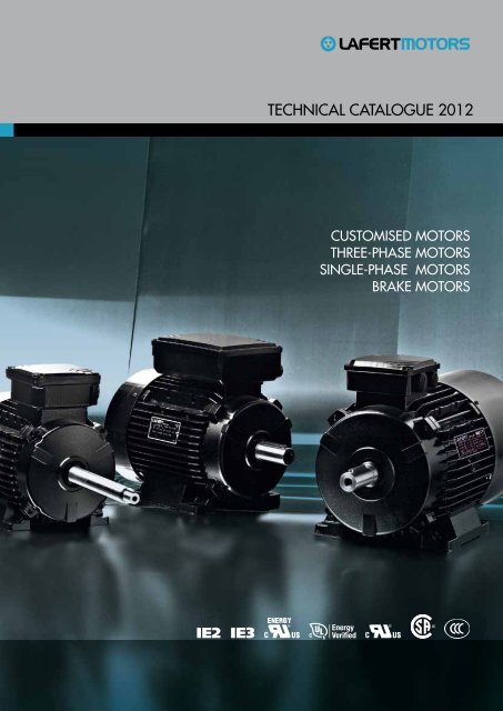
Technical caTalogue <strong>2012</strong><br />
cuSToMiSeD MoToRS<br />
ThRee-PhaSe MoToRS<br />
Single-PhaSe MoToRS<br />
BRaKe MoToRS<br />
IE2<br />
IE3
Technical caTalogue 1039/12
CONTENTS<br />
General information 3<br />
Product range 4<br />
StandardS and regulationS 10<br />
condition of inStallation 14<br />
toleranceS 15<br />
Mechanical deSign 16<br />
Degrees of protection<br />
Mounting arrangements<br />
Materials and painting<br />
Bearings<br />
Optional features<br />
Cooling, vibration and noise<br />
electrical deSign 25<br />
Rated voltage, frequency and current<br />
Insulation and temperature rise<br />
Starting rate<br />
Thermal protection<br />
Connection<br />
Encoder<br />
order data 31<br />
tHree-PHaSe motorS 33<br />
terMinal box 34<br />
connection diagraMS 36<br />
frequency converter 38<br />
SPare PartS 39<br />
tyPe deSignation 40<br />
PerforMance data 41<br />
Premium efficiency motors – IE3<br />
High efficiency motors – IE2<br />
Standard efficiency motors – IE1<br />
Pole change motors<br />
diMenSionS 54<br />
SinGle-PHaSe motorS 63<br />
terMinal box 64<br />
connection diagraMS 66<br />
electronic Starting device 67<br />
SPare PartS 68<br />
tyPe deSignation 69<br />
PerforMance data 70<br />
Standard motors<br />
Motors with starting capacitor<br />
Dual voltage motors<br />
Dual voltage motors with starting capacitor<br />
diMenSionS 74<br />
BraKe motorS 77<br />
technical deScriPtion and SPare PartS 78<br />
Motors with high torque DC brake<br />
Motors with high torque AC brake<br />
Motors with low torque DC brake<br />
connection diagraMS 84<br />
tyPe deSignation 87<br />
PerforMance data 88<br />
Standard efficiency motors – IE1<br />
High efficiency motors – IE2<br />
diMenSionS 96<br />
1
gENERal iNFORMaTiON<br />
General information - TEChNiCal CaTalOguE 1039/12<br />
3
PRODuCT RaNgE<br />
miSSion<br />
For 50 years the Lafert Group have been committing to continuous growth by being the<br />
global leading manufacturer of Customised Engineered Electric Motors and Drives<br />
with special focus on Industrial Automation, Energy Saving and Renewables.<br />
The Group have developed an excellent ability to adapt the highest quality standards<br />
to any specific market demands providing solutions for several applications and OEM<br />
requests.<br />
The Lafert Group’s range of products is divided in 5 product sectors:<br />
EnERgy EffICIEnt Motors, three-phase motors<br />
high efficiency, IE2 and premium efficiency, IE3<br />
enerGy efficient motors<br />
CuStOMISED Motors, single-phase, three-phase and<br />
brake motors in special execution<br />
cUStomiSed motors<br />
HIgH PERfORMAnCE Motors, permanent magnet<br />
synchronous motors and generators as well as the<br />
relevant drives<br />
HiGH Performance motors<br />
SERvO Motors & Drives, brushless servomotors and<br />
drives for industrial automation<br />
Servo motors & drives<br />
lIft Motors, permanent magnet synchronous gearless<br />
machines for elevators<br />
lift motors<br />
4 General information - TEChNiCal CaTalOguE 1039/12
PRODuCT RaNgE<br />
enerGy efficient motorS<br />
HIgH EffICIEnCy, EnERgy SAvIng<br />
IE2<br />
IE3<br />
The range of Energy Efficient Motors has been developed to meet the increasing<br />
demand for increased energy efficiency and energy saving products in Europe, North<br />
America and Australia after the introduction of directives imposing higher minimum<br />
efficiency levels.<br />
High Efficiency and Premium Efficiency Three-phase Motors up to 200 kW meeting<br />
the requirements of IE2 and IE3 internationally efficiency levels in accordance with IEC<br />
60034-30;2008 and test method IEC 60034-2-1;2007.<br />
Motors conforming to the higher efficiency standards for the North American market in<br />
accordance with EPAct Regulation (Energy Policy Act, 1992) and EISA Directive (Energy<br />
Independence and Security Act, 2007).<br />
In addition these motors are verified by ul underwriters laboratories Inc..<br />
The range of Energy Efficient Motors from Lafert is the first complete range of IE2 and<br />
IE3 motors available to worldwide Industry.<br />
General information - TEChNiCal CaTalOguE 1039/12<br />
5
PRODuCT RaNgE<br />
cUStomiSed motorS<br />
CuStOMISAtIOn, OuR CORE BuSInESS<br />
A wide range of Customised Motors with special execution, in order to optimise<br />
electrical and mechanical design for particular markets or specific OEM requests.<br />
Single-phase, Three-phase and Brake Motors manufactured ad hoc for non-standard<br />
applications according to customer’s demands: customised flanges and shafts, special<br />
electrical design for each duty request, complete tailor-made design, AC or DC brake<br />
coil to fit any applications, solutions to special environmental conditions (Smoke and<br />
Heat Exhaust Ventilation, Dust Ignition for Zone 22, Non Sparking Exn).<br />
6 General information - TEChNiCal CaTalOguE 1039/12
PRODuCT RaNgE<br />
HiGH Performance motorS<br />
PERMAnEnt MAgnEt SynCHROnOuS MOtORS SIgnIfICAntly REDuCE EnERgy COStS<br />
High Performance is a range of PM synchronous motors 0.37 kW to 22 kW, with<br />
variable speed and equipped with sensorless drives. By combining the technology of<br />
both brushless servo motors and AC motors, this range achieves the highest efficiency<br />
level IE4 – Super Premium Efficiency and is specifically designed for its energy saving<br />
potential and renewable energy applications.<br />
Permanent magnet technology, very high efficiency, compact design, reduced weight,<br />
low operating temperature.<br />
A separate catalogue is available.<br />
General information - TEChNiCal CaTalOguE 1039/12<br />
7
PRODuCT RaNgE<br />
Servo motorS & driveS<br />
A MODERn AnD COMPlEtE RAngE fOR InDuStRIAl AutOMAtIOn<br />
The range of Brushless Servo Motors is one of the most complete available on the<br />
market, with nominal torques 0.30 Nm to 150 Nm. Direct Drive Motors cover torques<br />
8 Nm to 1000 Nm.<br />
Thanks to its whole integrated manufacturing process, Lafert is one of the few<br />
independent manufacturers of servo motors and can supply a wide range of standard<br />
and tailor-made products for Industrial Automation giving excellent flexibility and high<br />
level of cost efficiency.<br />
The family of Servo Drives is especially engineering for brushless servo motors and DC<br />
motors providing particular versatility and adaptability when designing automated<br />
industrial machines.<br />
These products ensure high reliability and are subjected to strict tests in different loads<br />
and climatic conditions.<br />
A separate catalogue is available.<br />
8 General information - TEChNiCal CaTalOguE 1039/12
PRODuCT RaNgE<br />
lift motorS<br />
gEARlESS MACHInES fOR ElEvAtORS<br />
The lift range allows the manufacturing of systems where the traction machine is inside<br />
the elevator shaft, so there is no need for a machine room, with obvious space and cost<br />
savings and a more rational layout of the all components.<br />
Permanent Magnet gearless Synchronous Machines with compact design, reduced<br />
energy consumption, low noise level, high comfort and requiring less maintenance.<br />
Motors with torque up to 660 Nm for systems with a capacity load up to 1,275 kg,<br />
machines with TÜV SÜD Certifications, in compliance with the Specifications EN 81-1 and<br />
Lifts Directive 95/16/EC.<br />
A separate catalogue is available.<br />
General information - TEChNiCal CaTalOguE 1039/12<br />
9
STaNDaRDS aND REgulaTiONS<br />
qUality SyStem certificate<br />
The strictness of our quality control assures the flawless operation<br />
and reliability of our products. Our quality is confirmed by the<br />
Certificate ISO 9001:2000 awarded by CERMET, a certification<br />
body authorized by ACCREDIA.<br />
Safety StandardS<br />
Our motors comply with the requirements of the International<br />
Standard IEC 60034 for rotating electrical machines as well as<br />
with the following European Directives: low voltage Directive<br />
(LV) 2006/95/EC, Electromagnetic Compatibility Directive (EMC)<br />
2004/108/EC and RoHS Directive 2002/95/EC on the restriction<br />
of hazardous substances in electrical and electronic equipment.<br />
All products comply with the requirements of the Directive<br />
Machines (MD) 2006/42/EC. In accordance with this Directive,<br />
induction motors are components and intended solely for<br />
integration into other machines. Commissioning is forbidden until<br />
conformity of the end-product with this Directive is proved.<br />
The CE marking was applied for the first time in 1995.<br />
When operating the motor, the observance of the Regulation EN 60204-1 and safety<br />
instructions indicated in our Operating Instructions must be complied with.<br />
Motors complied with many other international standards are available on request:<br />
Motors approved by UL Underwriters Laboratories Inc.<br />
Motors approved by CSA<br />
Motors approved by CQC (small motors up to 1.1 kW – AM, AMBY, AMF series)<br />
efficiency StandardS<br />
IE1 IE2 IE3<br />
Efficiencies are harmonized to the International Standard IEC 60034-30;2008 that states<br />
new efficiency levels: Standard Efficiency IE1, High Efficiency IE2 and Premium Efficiency IE3.<br />
The efficiency levels are in accordance with the testing method IEC 60034-2-1;2007.<br />
High Efficiency motors according to EPAct legislation.<br />
Verified by UL Underwriters Laboratories Inc.<br />
Premium Efficiency motors according to EISA Directive.<br />
Verified by UL Environment.<br />
10 General information - TEChNiCal CaTalOguE 1039/12
STaNDaRDS aND REgulaTiONS<br />
new international efficiency levelS for motorS: ie codeS<br />
The International standard IEC 60034-30;2008 states the new efficiency levels IE1, IE2<br />
and IE3 for electric motors, ensuring an international common base for motor designing<br />
and classification, as well as for national legislative activities.<br />
The efficiency measurement method for motors has also been reviewed.<br />
The new standard IEC 60034-2-1;2007 provides for test conditions and efficiency<br />
measurement methods which are more accurate and replaces the previous standard EN<br />
60034-2;1996.<br />
The efficiency levels provided for by the standard for single speed, three-phase – brake<br />
motors included -50 Hz or 50/60 Hz, motors with rated output between 0,75 kW and 375<br />
kW, 2, 4 or 6 poles, on the basis of continuous duty operation S1 or intermittent periodic<br />
duty operation S3 are the following:<br />
• IE1 = Standard Efficiency<br />
• IE2 = High Efficiency<br />
• IE3 = Premium Efficiency<br />
However, IEC 60034-30 states only the requirements for the efficiency levels, thus<br />
creating shared measures worldwide. It does not state the motors to be supplied or the<br />
minimum efficiency level. This depends on any regional laws that are applicable.<br />
eUroPe – ecodeSiGn eUP directive (2005/32/ec)<br />
The EcoDesign EuP directive (2005/32/CE) states the ecodesign requirements for<br />
energy-using products.<br />
It is the Commission Regulation (EC) 640/2009 that specifies the efficiency requirements<br />
for electric motors and that introduces in all countries of the European Community the<br />
obligation of the IE2 minimum efficiency level as from 16th June 2011.<br />
At further dates, progressively higher minimum efficiency requirements will be established.<br />
The IE3 level will come in from 2015-2017.<br />
The scope of the Commission Regulation includes single speed, three-phase 50 Hz or<br />
50/60 Hz, squirrel cage asynchronous motors with rated output between 0.75 kW and<br />
375 kW, 2, 4 or 6 poles, on the basis of continuous duty operation S1.<br />
Motors to be exclusively exported out of the EU (machine distributors or manufacturers)<br />
may be produced and distributed with IE1 efficiency level even after 16th June 2011.<br />
To that end, a statement will have to be made to the manufacturer.<br />
United StateS, canada – eiSa enerGy indePendence and SecUrity act, 2007<br />
The Energy Independence and Security Act, 2007 (EISA) imposes in the USA and<br />
Canada Nema Premium Efficiency (IE3) as minimum level of efficiency as from 19th<br />
December 2010.<br />
EISA, which replaces the current 1992 Energy Policy Act (EPAct) legislation, sets out<br />
new efficiency restrictive limits for a wide range of three-phase motors, including brake<br />
motors with power ratings from 1 to 500 HP.<br />
General information - TEChNiCal CaTalOguE 1039/12<br />
11
STaNDaRDS aND REgulaTiONS<br />
EffICIEnCy vAluES fOR 50 Hz ACCORDIng tO IEC 60034-30;2008<br />
efficiency standard calculation: iec 60034-2-1;2007<br />
Output Standard Efficiency - IE1 High Efficiency - IE2 Premium Efficiency - IE3<br />
kW 2 poles 4 poles 6 poles 2 poles 4 poles 6 poles 2 poles 4 poles 6 poles<br />
0.75 72.1 72.1 70.0 77.4 79.6 75.9 80.7 82.5 78.9<br />
1.1 75.0 75.0 72.9 79.6 81.4 78.1 82.7 84.1 81.0<br />
1.5 77.2 77.2 75.2 81.3 82.8 79.8 84.2 85.3 82.5<br />
2.2 79.7 79.7 77.7 83.2 84.3 81.8 85.9 86.7 84.3<br />
3 81.5 81.5 79.7 84.6 85.5 83.3 87.1 87.7 85.6<br />
4 83.1 83.1 81.4 85.8 86.6 84.6 88.1 88.6 86.8<br />
5.5 84.7 84.7 83.1 87.0 87.7 86.0 89.2 89.6 88.0<br />
7.5 86.0 86.0 84.7 88.1 88.7 87.2 90.1 90.4 89.1<br />
11 87.6 87.6 86.4 89.4 89.8 88.7 91.2 91.4 90.3<br />
15 88.7 88.7 87.7 90.3 90.6 89.7 91.9 92.1 91.2<br />
18.5 89.3 89.3 88.6 90.9 91.2 90.4 92.4 92.6 91.7<br />
22 89.9 89.9 89.2 91.3 91.6 90.9 92.7 93.0 92.2<br />
30 90.7 90.7 90.2 92.0 92.3 91.7 93.3 93.6 92.9<br />
37 91.2 91.2 90.8 92.5 92.7 92.2 93.7 93.9 93.3<br />
45 91.7 91.7 91.4 92.9 93.1 92.7 94.0 94.2 93.7<br />
55 92.1 92.1 91.9 93.2 93.5 93.1 94.3 94.6 94.1<br />
75 92.7 92.7 92.6 93.8 94.0 93.7 94.7 95.0 94.6<br />
90 93.0 93.0 92.9 94.1 94.2 94.0 95.0 95.2 94.9<br />
110 93.3 93.3 93.3 94.3 94.5 94.3 95.2 95.4 95.1<br />
132 93.5 93.5 93.5 94.6 94.7 94.6 95.4 95.6 95.4<br />
160 93.7 93.8 93.8 94.8 94.9 94.8 95.6 95.8 95.6<br />
200-375 94.0 94.0 94.0 95.0 95.1 95.0 95.8 96.0 95.8<br />
EffICIEnCy vAluES fOR 60 Hz ACCORDIng tO IEC 60034-30;2008<br />
efficiency standard calculation: iec 60034-2-1;2007<br />
Output Standard Efficiency - IE1 High Efficiency - IE2 Premium Efficiency - IE3<br />
kW 2 poles 4 poles 6 poles 2 poles 4 poles 6 poles 2 poles 4 poles 6 poles<br />
0.75 77.0 78.0 73.0 75.5 82.5 80.0 77.0 85.5 82.5<br />
1.1 78.5 79.0 75.0 82.5 84.0 85.5 84.0 86.5 87.5<br />
1.5 81.0 81.5 77.8 84.0 84.0 86.5 85.5 86.5 88.5<br />
2.2 81.5 83.0 78.5 85.5 87.5 87.5 86.5 89.5 89.5<br />
3.7 84.5 85.0 83.5 87.5 87.5 87.5 88.5 89.5 89.5<br />
5.5 86.0 87.0 85.0 88.5 89.5 89.5 89.5 91.7 91.0<br />
7.5 87.5 87.5 86.0 89.5 89.5 89.5 90.2 91.7 91.0<br />
11 87.5 88.5 89.0 90.2 91.0 90.2 91.0 92.4 91.7<br />
15 88.5 89.5 89.5 90.2 91.0 90.2 91.0 93.0 91.7<br />
18.5 89.5 90.5 90.2 91.0 92.4 91.7 91.7 93.6 93.0<br />
22 89.5 91.0 91.0 91.0 92.4 91.7 91.7 93.6 93.0<br />
30 90.2 91.7 91.7 91.7 93.0 93.0 92.4 94.1 94.1<br />
37 91.5 92.4 91.7 92.4 93.0 93.0 93.0 94.5 94.1<br />
45 91.7 93.0 91.7 93.0 93.6 93.6 93.6 95.0 94.5<br />
55 92.4 93.0 92.1 93.0 94.1 93.6 93.6 95.4 94.5<br />
75 93.0 93.2 93.0 93.6 94.5 94.1 94.1 95.4 95.0<br />
90 93.0 93.2 93.0 94.5 94.5 94.1 95.0 95.4 95.0<br />
110 93.0 93.5 94.1 94.5 95.0 95.0 95.0 95.8 95.8<br />
150 94.1 94.5 94.1 95.0 95.0 95.0 95.4 96.2 95.8<br />
185-375 94.1 94.5 94.1 95.4 95.4 95.0 95.8 96.2 95.8<br />
12 General information - TEChNiCal CaTalOguE 1039/12
STaNDaRDS aND REgulaTiONS<br />
GloBally minimUm efficiency StandardS<br />
Country Product range Law / Regulation Minimum efficiency level Next steps<br />
EUROPE<br />
RUSSIA<br />
SWITZERLAND<br />
TURKEY<br />
USA<br />
CANADA<br />
MEXICO<br />
BRAZIL<br />
CHILE<br />
CHINA<br />
HONG KONG<br />
INDIA<br />
ISRAEL<br />
JAPAN<br />
KOREA<br />
SINGAPORE<br />
TAIWAN<br />
SAUDI ARABIA<br />
UNITED ARAB<br />
EMIRATES<br />
SOUTH AFRICA<br />
AUSTRALIA<br />
NEW ZELAND<br />
400 V ± 10%; 50 Hz<br />
0.75 - 375 kW - 2-6 poles<br />
up to 690 V ± 10%; 50 Hz<br />
1 - 400 kW - All poles<br />
400 V ± 10%; 50 Hz<br />
0.75 - 375 kW - 2-6 poles<br />
400 V ± 10%; 50 Hz<br />
0.75 - 375 kW - 2-6 poles<br />
460 V ± 10%; 60 Hz<br />
1 - 200 HP - 2-6 poles<br />
460 V/575 V ± 10%; 60 Hz<br />
1 - 200 HP - 2-6 poles<br />
460 V ± 10%; 60 Hz<br />
1 - 200 HP - 2-6 poles<br />
220/380/440/460/480 V<br />
± 10%; 60 Hz<br />
0.75 - 250 kW - 2-8 poles<br />
380/400/420/440/460/690 V<br />
± 10%; 50 Hz<br />
0.75 Kw - 7.5 kW - 2-6 poles<br />
380 V ± 10%; 50 Hz<br />
0.55 - 315 kW - 2-6 poles<br />
380 V ± 10%; 50 Hz<br />
0.75 - 375 kW - 2-6 poles<br />
415 V/690 V ± 10%; 50 Hz<br />
0.37 - 315 kW - 2-8 poles<br />
400 V ± 10%; 50 Hz<br />
0.75 - 185 kW - 2-8 poles<br />
200/220/400/440 V<br />
± 10%; 50/60 Hz<br />
0.2 - 160 kW - 2-6 poles<br />
up to 600 V ± 10%; 60 Hz<br />
0.75 - 200 kW - 2-6 poles<br />
415 V ± 10%; 50 Hz<br />
1.1 - 90 kW - 2-4 poles<br />
< 600 V ± 10%; 60 Hz<br />
0.37 - 200 kW - 2-8 poles<br />
380 V/ 460 V ± 5%; 60 Hz<br />
all kW - all poles<br />
400 V ± 10%; 50 Hz<br />
0.75 - 375 kW - 2-6 poles<br />
400 V/525 V ± 10%;50 Hz<br />
0.75 - 375 kW - 2-6 poles<br />
415 V/690 V ± 10%; 50 Hz<br />
0.75 - 186 kW - 2-8 poles<br />
EC 640/2009<br />
GOST R 51677-2000 -<br />
EnV<br />
IE2<br />
compulsory<br />
16.06.2011<br />
IE2<br />
compulsory<br />
01.07.2011<br />
01.01.2015 - IE3 from 7.5 to 375 kW<br />
or IE2 motor with frequency converter<br />
01.01.2017 - IE3 from 0.75 to 375 kW or<br />
IE2 motor with frequency converter<br />
For extension of regulations in 2015 and<br />
2017, Swiss Energy Act will be revised in<br />
time<br />
EC 640/2009 IE1 No decision yet. Will follow probably the<br />
EU timeline state initiative and customer<br />
awareness for IE2<br />
Nema EPAct<br />
EISA 2007<br />
CSA C390<br />
Nema EPAct<br />
EISA 2007<br />
NBR 17094-1<br />
Regulation 553<br />
NCH 3086<br />
GB 18613-2006<br />
Mandatary Buildings<br />
Energy Efficiency Bill<br />
IS:12615<br />
IS:5289<br />
JIS C 4210<br />
JIS C 4212<br />
KS C 4202<br />
IE3<br />
compulsory<br />
19.12.2010<br />
IE3<br />
compulsory<br />
01.01.2011<br />
IE3<br />
compulsory<br />
01.01.2011<br />
IE2<br />
compulsory<br />
08.12.2009<br />
IE2<br />
compulsory<br />
04.01.2011<br />
IE2<br />
is planned<br />
IE2<br />
introduction stage since<br />
Dec 2009<br />
IE2<br />
compulsory<br />
01.06.2011<br />
IE2<br />
compulsory 01.02.2008<br />
IE2<br />
expected<br />
IE2<br />
compulsory 01.01.2010<br />
Will follow USA model<br />
01.01.2015 - IE3 from 7.5 to 375 kW<br />
or IE2 motor with frequency converter<br />
01.01.2017 - IE3 from 0.75 to 375 kW or<br />
IE2 motor with frequency converter<br />
IE3 from 01.01.2014<br />
No law, efficiency per JIS standards. IEC<br />
60034-30 will be integrated into JIS in <strong>2012</strong><br />
SS530:2006 IE2 Only government projects compulsory IE2<br />
CNS14400 IE2 No plan to adapt IEC 60034-30. IE2 motors<br />
can be certified acc. to CNS 14400 as high<br />
efficiency motors<br />
No regulation -<br />
No regulation IE1 No regional standards regarding a minimun<br />
efficiency<br />
IEC 60034-30<br />
AS/NZS 1359.5-2004<br />
IE1<br />
IE2<br />
compulsory 01.04.2006<br />
IE3 expected for near future<br />
General information - TEChNiCal CaTalOguE 1039/12<br />
13
CONDiTiONS OF iNSTallaTiON<br />
The motors comply with the relevant standards and regulations, especially:<br />
ELECTRICAL<br />
Rating and performance IEC 60034-1<br />
Methods for determining losses and efficiency using tests IEC 60034-2<br />
Standard method for determing losses and efficiency from tests IEC 60034-2-1<br />
Efficiency classes of single speed, three-phase, cage-induction motors (IE-code) IEC 60034-30<br />
Terminal markings and direction of rotation IEC 60034-8<br />
Starting performance IEC 60034-12<br />
Standard voltages IEC 60038<br />
Insulating materials IEC 60085<br />
MECHANICAL<br />
Dimensions and output ratings IEC 60072<br />
Mounting dimensions and relationship frame sizes-output ratings, IM B3, IM B5, IM B14 IEC 60072<br />
Cylindrical shaft ends for electric motors IEC 60072<br />
Degrees of protection IEC 60034-5<br />
Methods of cooling IEC 60034-6<br />
Mounting arrangements IEC 60034-7<br />
Noise limits IEC 60034-9<br />
Mechanical vibration IEC 60034-14<br />
Mounting flanges DIN 42948<br />
Tolerances of mounting and shaft extensions DIN 42955<br />
Classification of environmental conditions IEC 60721-2-1<br />
Mechanical vibration; balancing ISO 8821<br />
The motors are designed for operation at altitudes ≤ 1000 m above sea-level and at<br />
ambient temperatures of up to 40° C. Exceptions are indicated on the rating plate.<br />
The motors conform to degree of protection IP 55 to IEC 60034-5 1) . Higher protection<br />
on request.<br />
The standard design for horizontal mounting is suitable for indoor and protected outdoor<br />
installation, climate group moderate (see page 18) (temperature of coolant -20° to +40° C).<br />
For unprotected outdoor installation or severe climatic conditions (moisture category<br />
wet, climate group worldwide, extremely dusty site conditions, aggressive industrial<br />
atmosphere, danger of storm rain and coastal climate, danger of attack by termites, etc.),<br />
as well as vertical mounting, special protective measures are recommended, such as:<br />
• Protective cowl (for vertical shaft-down motors)<br />
• For vertical shaft-up motors additional bearing seal and flange drainage<br />
• Special paint finish<br />
• Treatment of winding with protective moisture-proof varnish<br />
• Anti-condensation heating (possibly winding heating)<br />
• Condensation drain holes<br />
The special measures to be applied have to be agreed with the factory once the<br />
conditions of installation have been settled.<br />
The corresponding conditions of installation have to be clearly indicated in the order.<br />
1) IP54 for brake motors AMS and for AMBZ, AMBY from size 63 to 132<br />
14 General information - TEChNiCal CaTalOguE 1039/12
TOlERaNCES<br />
electrical toleranceS<br />
For industrial motors to En 60034-1, certain tolerances must be allowed on guaranteed<br />
values, taking into consideration the necessary tolerances for the manufacture of such<br />
motors and the materials used. The standard includes the following remarks:<br />
1- It is not intended that guarantees necessarily have to be given for all or any of the<br />
items involved. Quotations including guaranteed values subject to tolerances should say<br />
so, and the tolerances should be in accordance with the table.<br />
2- Attention is drawn to the different interpretation of the term guarantee. In some<br />
countries a distinction is made between guaranteed values and typical or declared values.<br />
3- Where a tolerance is stated in only one direction, the value is not limited in the other<br />
direction.<br />
values for<br />
Efficiency (η)<br />
(by indirect determination)<br />
tolerance<br />
- 0.15 (1 - η) at P N<br />
≤ 150 kW<br />
- 0.1 (1 - η) at P N<br />
> 150 kW<br />
Power factor (cos ϕ)<br />
1 - cos ϕ<br />
6<br />
, minimum 0.02, maximum 0.07<br />
Slip (s)<br />
(at rated load and at working temperature)<br />
Breakaway starting current (I A<br />
)<br />
(in the starting circuit envisaged)<br />
Breakaway torque (M A<br />
)<br />
Pull-up torque (M S<br />
)<br />
Pull-out torque (M K<br />
)<br />
Moment of inertia (J)<br />
± 20 % of the guaranteed slip at P N<br />
≥ 1 kW<br />
± 30 % of the guaranteed slip at P N<br />
< 1 kW<br />
+ 20 % of the guaranteed starting current<br />
(no lower limit)<br />
- 15 % and + 25 % of the guaranteed breakaway torque<br />
(+ 25 % may be exceeded by agreement)<br />
- 15 % of the guaranteed value<br />
- 10 % of the guaranteed value<br />
(after allowing for this tolerance, M K<br />
/M N<br />
not less than 1.6)<br />
± 10 % of the guaranteed value<br />
mecHanical toleranceS<br />
According to IEC 60072-1, the following tolerances on mechanical dimensions of electric<br />
motors are permitted:<br />
Parameter Code tolerance<br />
Shaft height H - up to 250 -0.5 mm<br />
- over 250 -1 mm<br />
- from 11 to 28 mm j6<br />
Diameter of shaft end 1) D-DA - from 38 to 48 mm k6<br />
- from 55 to 100 mm m6<br />
Hub key width F-FA h9<br />
flange spigot N - up to 132 j6<br />
- over size 132 h6<br />
1) Centerings holes in shaft extension to DIN 332 part 2<br />
General information - TEChNiCal CaTalOguE 1039/12<br />
15
MEChaNiCal DESigN<br />
deGreeS of Protection<br />
Degrees of mechanical protection for machines are designated in accordance with IEC<br />
60034-5 by the letters IP and two characteristic numerals.<br />
First numeral: Protection against contact<br />
and ingress of foreign bodies<br />
Second numeral:<br />
Protection against ingress of water<br />
IP<br />
Description<br />
IP<br />
Description<br />
0 No special protection<br />
1 Protection against solid foreign<br />
bodies larger than 50 mm<br />
(Example: inadvertent contact with<br />
the hand)<br />
2 Protection against solid foreign<br />
bodies larger than 12 mm<br />
(Example: inadvertent contact with<br />
the fingers)<br />
3 Protection against solid foreign<br />
bodies larger than 2.5 mm<br />
(Example: Wires, tools)<br />
4 Protection against solid foreign<br />
bodies larger than 1 mm<br />
(Example: Wires, bands)<br />
5 Protection against dust<br />
(harmful deposits of dust)<br />
6 Complete protection against dust<br />
0 No special protection<br />
1 Protection against vertically<br />
falling water drops (condensation)<br />
2 Protection against dropping water<br />
when inclined by up to 15°<br />
3 Protection against waterspray at<br />
up to 60° from vertical<br />
4 Protection against water splashed<br />
from any direction<br />
5 Protection against water<br />
projected by a nozzle from<br />
any direction<br />
6 Protection against heavy seas or<br />
water projected in powerful jets<br />
7 Protection when submerged<br />
between 0.15 and 1 m.<br />
8 Protection when continuously<br />
submerged in water at conditions<br />
agreed between the<br />
manufacturer and the user<br />
16 General information - TEChNiCal CaTalOguE 1039/12
MEChaNiCal DESigN<br />
moUntinG arranGementS<br />
Mounting arrangements for rotating electrical machines are designated according to IEC<br />
60034-7, Code I (in brackets Code II).<br />
foot mounting flange mounting Motors without endshield<br />
IM B3 (IM 1001)<br />
IM B6 (IM 1051)<br />
IM B7 (IM 1061)<br />
IM B8 (IM 1071)<br />
IM v5 (IM 1011)<br />
IM B5 (IM 3001)<br />
Flange type A to<br />
DIN 42 948 at<br />
drive end<br />
IM v1 (IM 3011)<br />
Flange type A to<br />
DIN 42 948 at<br />
drive end<br />
IM v3 (IM 3031)<br />
Flange type A to<br />
DIN 42 948 at<br />
drive end<br />
IM B35 (IM 2001)<br />
Flange type A to<br />
DIN 42 948 at<br />
drive end<br />
IM B14 (IM 3601)<br />
Flange type C to<br />
DIN 42 948 at<br />
drive end<br />
IM B9 (IM 9101)<br />
without endshield<br />
and without<br />
ball bearings<br />
on drive end<br />
IM v8 (IM 9111)<br />
without endshield<br />
and without<br />
ball bearings<br />
on drive end<br />
IM v9 (IM 9131)<br />
without endshield<br />
and without<br />
ball bearings<br />
on drive end<br />
IM B15 (IM 1201)<br />
without endshield<br />
and without<br />
ball bearings<br />
on drive end<br />
IM v6 (IM 1031)<br />
IM v18 (IM 3611)<br />
Flange type C to<br />
DIN 42 948 at<br />
drive end<br />
IM B34 (IM 2101)<br />
Flange type C to<br />
DIN 42 948 at<br />
drive end<br />
IM v19 (IM 3631)<br />
Flange type C to<br />
DIN 42 948 at<br />
drive end<br />
All standard motors can be installed according to the following mounting arrangements:<br />
frame Size B3 B5 B35 Based on B5 Based on B3 Based on B35<br />
v1 v3 v5 v6 B6 B7 B8 v15 v36<br />
56-160 √ √ √ √ √ √ √ √ √ √ √ √<br />
180-225 √ √ √ √ * * * * * * * *<br />
250-315 √ * √ * * * * * * * * *<br />
* for high loads refer to us<br />
It is essential to state the desired mounting arrangement when ordering, as the<br />
constructive design depends partly on the mounting arrangement.<br />
General information - TEChNiCal CaTalOguE 1039/12<br />
17
MEChaNiCal DESigN<br />
materialS<br />
Motor parts frame size Material<br />
Motor housing 56 - 160 Aluminium alloy<br />
180 - 315 Cast iron<br />
Endshield 56 - 160 Aluminium alloy*<br />
180 - 315 Cast iron<br />
Flanged endshield 56 - 160 Aluminium alloy*<br />
180 - 315 Cast iron<br />
Fan cover 56 - 112 Plastics<br />
56 - 112 Sheet steel (optional) 1)<br />
132 - 315 Sheet steel<br />
Fan 56 - 315 Plastics<br />
56 - 160 Aluminium alloy (optional)<br />
Terminal box 56 - 112 Plastics<br />
56 - 112 Aluminium alloy (optional) 2)<br />
132 - 160 Aluminium alloy<br />
180 - 315 Cast iron<br />
1) Standard for brake motors type AMBY and AMBZ and for AMS 112<br />
2) For three-phase motors only<br />
* Cast iron option for 112-132<br />
Paint finiSH<br />
nORMAl fInISH<br />
Suitable for climate group Moderate to IEC 60721-2-1, e.g. indoor and outdoor<br />
installation.<br />
For short periods: up to 100% rel. humidity at temperatures up to +30° C.<br />
Continuously: up to 85% rel. humidity at temperatures up to +25° C.<br />
Standard paint color: RAL 9005.<br />
SPECIAl fInISH K1<br />
Suitable for climate group Worldwide to IEC 60721-2-1, e.g. outdoor installation in<br />
corrosive chemical and marine atmospheres.<br />
For short periods: up to 100% rel. humidity at temperatures up to +35° C.<br />
Continuously: up to 98% rel. humidity at temperatures up to +30° C.<br />
18 General information - TEChNiCal CaTalOguE 1039/12
MEChaNiCal DESigN<br />
BearinGS<br />
ClASSIfICAtIOn Of BEARIngS (StAnDARD DESIgn) 1)<br />
Bearings for standard design have permanent lubrication<br />
Ball bearings to ISO15 (DIN 625)<br />
frame size Poles DE - nDE Dimension<br />
56 2 + 4 6201-2Z 12x32x10<br />
63 2 + 4 6202-2Z 15x35x11<br />
71 2 - 8 6203-2Z 17x40x12<br />
80 2 - 8 6204-2Z C3 20x47x14<br />
90 2 - 8 6205-2Z C3 25x52x15<br />
100 2 - 8 6206-2Z C3 30x62x16<br />
112 2 - 8 6306-2Z C3 30x72x19<br />
132 2 - 8 6208-2Z C3 40x80x18<br />
160 2 - 8 6309-2Z C3 45x100x25<br />
180 2 - 8 6311 C3 55x120x29<br />
200 2 - 8 6312 C3 60x130x31<br />
225 2 - 8 6313 C3 65x140x33<br />
250 2 - 8 6314 C3 70x150x35<br />
280 2 - 8 6316 C3 80x170x39<br />
315 2 6317 C3 85x180x41<br />
315 4 - 8 NU319 C3 - 6319 C3 95x200x45<br />
1) With regard on bearings for special design, consult us<br />
luBRICAtIOn nOtE<br />
Permanent lubrication up to 160 frame<br />
180 frame up with regreasing facility lubrication nipple is a flat M10x1 to DIN 3404<br />
ROllER BEARIngS<br />
Roller bearings available as an option. Please consult us.<br />
BearinG arranGement<br />
frame size Bearing DE Bearing nDE Spring-loaded<br />
56 - 160 Standard motors Non-locating bearing Non-locating bearing Non-drive end<br />
63 - 160 Brake motors Non-locating bearing Locating bearing Drive end<br />
180 - 315 Standard motors Locating bearing Non-locating bearing Non-drive end<br />
General information - TEChNiCal CaTalOguE 1039/12<br />
19
MEChaNiCal DESigN<br />
Belt drive<br />
The data apply only to the normal drive end shaft extension of IM B3 motors with one speed.<br />
Calculation of belt drive:<br />
19120 · P · k<br />
FR =<br />
D1 · n<br />
FR = Radial shaft load in N<br />
P = Output in kW<br />
n = Speed in min -1<br />
D1 = Pulley diameter in m<br />
k = Belt tension factor, varying with the type of belt, assumed to be approximately:<br />
3-4 for normal flat belt without idler pulley<br />
2-2.5 for normal flat belt with idler pulley<br />
2.2-2.5 for V-belt<br />
For exact data apply to the belt manufacturer.<br />
PermiSSiBle axial forceS<br />
Maximum permissible axial forces without additional radial forces*<br />
frame Horizontal shaft vertical shaft - force upwards vertical shaft - force downwards<br />
size 3000 1500 1000 750 3000 1500 1000 750 3000 1500 1000 750<br />
min -1 min -1 min -1 min -1 min -1 min -1 min -1 min -1 min -1 min -1 min -1 min -1<br />
kn kn kn kn kn kn kn kn kn kn kn kn<br />
56 0.16 0.21 - - 0.18 0.22 - - 0.15 0.19 - -<br />
63 0.19 0.26 - - 0.21 0.28 - - 0.17 0.24 - -<br />
71 0.23 0.33 0.33 0.37 0.26 0.35 0.36 0.39 0.21 0.30 0.31 0.34<br />
80 0.32 0.44 0.46 0.50 0.34 0.47 0.48 0.53 0.29 0.41 0.43 0.47<br />
90 0.34 0.48 0.49 0.54 0.38 0.47 0.53 0.58 0.31 0.44 0.46 0.51<br />
100 0.48 0.68 0.70 0.77 0.54 0.74 0.76 0.83 0.43 0.62 0.64 0.71<br />
112 0.48 0.68 0.70 0.77 0.56 0.75 0.77 0.84 0.40 0.60 0.62 0.69<br />
132 S 0.80 1.13 1.16 1.28 1.00 1.32 1.36 1.47 0.61 0.93 0.97 1.08<br />
132 M 0.78 1.09 1.13 1.24 0.99 1.30 1.33 1.45 0.58 0.89 0.92 1.03<br />
160 M 0.84 1.18 1.21 1.33 1.18 1.52 1.56 1.68 0.50 0.83 0.87 0.99<br />
160 l 0.82 1.15 1.18 1.30 1.18 1.51 1.55 1.67 0.46 0.79 0.82 0.94<br />
180 0.82 1.15 1.18 1.30 1.18 1.51 1.55 1.67 0.46 0.79 0.82 0.94<br />
200 0.82 1.15 1.18 1.30 1.18 1.51 1.55 1.67 0.46 0.79 0.82 0.94<br />
225 1.10 1.60 1.90 2.40 2.10 2.60 2.90 3.40 0.30 0.70 1.00 1.50<br />
250 1.00 1.60 2.00 2.50 2.30 2.70 3.20 3.70 0.20 0.60 1.10 1.50<br />
280 1.70 1.90 2.40 2.90 2.90 3.10 3.60 3.70 0.15 0.30 0.80 1.00<br />
315 2.00 14.00 14.00 14.00 3.60 8.00 9.20 7.40 1.00 1.90 2.40 2.90<br />
Values for 50 Hz. For service on 60 Hz, reduce values by 10%<br />
* Consult according to direction of force<br />
20 General information - TEChNiCal CaTalOguE 1039/12
MEChaNiCal DESigN<br />
PermiSSiBle radial forceS<br />
Without additional axial force (Ball bearings)<br />
Nominal life = 20.000 h (Lh10)<br />
FR = permissible radial force in kN in load point corresponding to half shaft extension<br />
frame 3000 1500 1000 750<br />
size min -1 min -1 min -1 min -1<br />
kn kn kn kn<br />
56 0.34 0.42 - -<br />
63 0.38 0.48 - -<br />
71 0.46 0.58 0.67 0.73<br />
80 0.59 0.83 0.86 0.94<br />
90 0.67 0.94 0.97 1.07<br />
100 0.92 1.29 1.33 1.47<br />
112 0.93 1.30 1.34 1.48<br />
132 S 1.35 1.90 1.96 2.15<br />
132 M 1.40 1.97 2.03 2.23<br />
160 M 1.55 2.17 2.23 2.46<br />
160 l 1.58 2.22 2.29 2.52<br />
180 M 3.00 4.44 4.55 4.76<br />
180 l 3.02 4.47 4.58 4.79<br />
200 l 5.24 6.85 8.01 8.94<br />
225 M 6.11 7.80 9.09 10.12<br />
250 M 6.79 8.82 10.31 11.45<br />
280 S 7.76 11.90 13.87 15.44<br />
280 M 7.79 11.99 13.97 15.55<br />
315 S/M 7.02 11.35 13.40 15.13<br />
315 l 7.03 11.37 13.35 15.09<br />
General information - TEChNiCal CaTalOguE 1039/12<br />
21
MEChaNiCal DESigN<br />
SPecial endSHieldS and flanGeS<br />
Full range of smaller sized and over sized flanges<br />
frame Smaller sized flange Over sized flange<br />
size IM B5 1) IM B14 IM B5 IM B14<br />
56 NA NA NA 63<br />
63 56 56 71 3) 71-80<br />
71 56-63 63 80-90 80-90<br />
80 63-71 63-71 NA 90-100<br />
90 S-l 63-71 71-80 100 3) 100-112<br />
100 l 71-80 90 NA 132<br />
112 M 80 2) -90 2) 90 132 7) 132<br />
132 S 112 2) 112 NA<br />
1) 4)<br />
160<br />
132 M 112 112 160 4) 160<br />
160 M NA 132 NA NA<br />
160 l NA 132 NA NA<br />
Possibility to fit over sized bearings<br />
frame<br />
size IM B3 IM B5 IM B14<br />
Aluminium endshields and flanges with steel insert<br />
frame Endshield Endshield<br />
size DE nDE IM B5 IM B14<br />
56 NA NA NA<br />
63 6203-6205 6203 6203-6205<br />
71 6204-6205 6204-6205 6204-6205<br />
80 6205-6206 6205-6206 6205-6206<br />
90 S-l 6206 6206-6308 6206<br />
100 l 6306 6306-6208 6306<br />
112 M 6208 6208 6208<br />
132 S 6308-6309 6308 6308 4)<br />
132 M 6308-6309 6308-6309 6309<br />
160 M NA 6310 6310<br />
160 l NA 6310 6310<br />
71 A A A NA<br />
80 A A A A<br />
90 S-l A A NA NA<br />
100 l A A A NA<br />
112 M A A A NA<br />
132 S NA NA NA NA<br />
132 M NA NA A 5) NA<br />
160 M NA NA NA NA<br />
160 l NA NA NA NA<br />
For higher output (progressive motor) please consult us<br />
Cast iron endshields and flanges<br />
frame Endshield Endshield Regreasing device<br />
size DE nDE IM B5 IM B14 DE nDE IM B5 IM B14<br />
71 NA NA NA NA NA NA NA NA<br />
80 A 6) A 6) NA NA NA NA NA NA<br />
90 S-l A 6) A 6) NA NA NA NA NA NA<br />
100 l A 6) A 6) NA NA NA NA NA NA<br />
112 M A 6) A 6) NA NA NA NA NA NA<br />
132 S A A A A NA NA A A<br />
132 M A A A A A A A A<br />
160 M A A A A A A A A<br />
160 l A A A A A A A A<br />
A Available<br />
NA Not available<br />
1) Not available for all motor ratings; consult us<br />
2) Cast iron endshield with radial slotted holes<br />
3) Not interchangeable with standard execution<br />
4) Cast iron endshield<br />
5) Only with oversized bearing (6308)<br />
6) Special mechanical design<br />
7) Only with oversized bearing (6208)<br />
22 General information - TEChNiCal CaTalOguE 1039/12
MEChaNiCal DESigN<br />
coolinG<br />
Surface cooling, independent of the direction of rotation.<br />
Motors type AM available without internal fan as type AG, e.g. for installation in a<br />
directed air stream (outputs on request).<br />
viBration<br />
The amplitude of vibration in electric motors is governed by En 60034-14 Mechanical<br />
vibration of rotating electrical machines with shaft heights 56 and larger - methods of<br />
measurement and limits.<br />
Standard motors are designed to vibration grade A (normal). Vibration grade B is available<br />
at extra cost.<br />
Rotors are at present dynamically balanced with half key fitted as per DIN ISO 8821.<br />
Other balancing only on request.<br />
The motors are identified as follows:<br />
“H” or “blank” means balanced with half key<br />
“F” means balanced with full key<br />
“N” means no key<br />
POSITION AND DIMENSIONS OF KEY<br />
frame Poles d x l1 b x h l2 l3 t<br />
size<br />
t<br />
l2<br />
l1<br />
b<br />
h<br />
l3<br />
d<br />
56 9 x 20 3 x 3 15 2.5 10.2<br />
63 11 x 23 4 x 4 15 4 12.5<br />
71 14 x 30 5 x 5 20 6 16<br />
80 19 x 40 6 x 6 30 6 21.5<br />
90 24 x 50 8 x 7 40 6 27<br />
100 28 x 60 8 x 7 50 6 31<br />
112 28 x 60 8 x 7 50 6 31<br />
132 38 x 80 10 x 8 70 6 41<br />
160 42 x 110 12 x 8 100 6 45<br />
180 48 x 110 14 x 9 90 5 51.5<br />
200 55 x 110 16 x 10 90 5 59<br />
225 2 55 x 110 16 x 10 90 5 59<br />
225 4 60 x 140 18 x 11 110 5 64<br />
250 2 60 x 140 18 x 11 110 5 64<br />
250 4 65 x 140 20 x 11 110 5 74.5<br />
280 2 65 x 140 18 x 11 110 5 69<br />
280 4 75 x 140 20 x 12 140 5 85<br />
315 2 65 x 140 18 x 11 125 5 69<br />
315 4 80 x 170 22 x 14 160 5 85<br />
Dimensions in mm.<br />
For larger shafts in special design the dimensions l2 and l3 are maintained.<br />
General information - TEChNiCal CaTalOguE 1039/12<br />
23
MEChaNiCal DESigN<br />
anti-condenSation Heater<br />
On request, motors which due to strong temperature fluctuations are exposed to<br />
condensation during standstill, can be fitted against surcharge with an anti-condensation<br />
heater (space heater).<br />
For supply voltage and heater rating please refer to the following table:<br />
frame size Supply voltage (v) Heater rating per motor (W)<br />
112 - 160 110 or 230 25<br />
180 - 225 110 or 230 50<br />
250 - 280 110 or 230 50<br />
315 110 or 230 75<br />
During operation of the motor, the heating must be switched off.<br />
noiSe<br />
The noise level of an electrical machine is determined by measuring the sound pressure level in<br />
accordance with curve A of the sound level meter to EN 60651 and is indicated in dB (A).<br />
The permitted noise levels of electrical machines are fixed in EN 60034-9 (IEC 34-9). The noise<br />
level of our motors is well below these limit values.<br />
Air-borne sound measurements are carried out in an anechoic testing chamber to EN 21680-<br />
ISO 1680.<br />
Speed corresponding to a mains frequency of 50 Hz and the number of poles.<br />
noiSe levelS<br />
The noise values listed below refer to 50 Hz at rated voltage with a tolerance of up to + 3 dB(A).<br />
Values for pole-changing motors on request. For 60 Hz supply values are 3-5 dB(A) higher.<br />
Sound pressure level LpA and sound power level LWA for three-phase single-speed motors with<br />
dimensions and output ratings to IEC 60072<br />
frame 2 poles 4 poles 6 poles 8 poles<br />
size lWA lpA lWA lpA lWA lpA lWA lpA<br />
56 57 48 47 38<br />
63 58 49 47 38<br />
71 61 52 51 42 49 40<br />
80 72 60 60 48 52 40 47 35<br />
90 74 62 61 49 58 46 54 42<br />
100 78 66 62 50 62 51 58 46<br />
112 80 68 65 53 65 53 58 46<br />
132 81 72 71 59 69 57 64 52<br />
160 87 74 75 62 71 58 69 56<br />
180 90 77 78 66 74 62 72 60<br />
200 91 78 80 68 77 65 74 62<br />
225 92 80 88 76 80 68 75 64<br />
250 93 81 88 76 80 68 75 64<br />
280 93 82 89 79 83 71 81 70<br />
315 93 82 89 79 83 71 81 70<br />
24 General information - TEChNiCal CaTalOguE 1039/12
ElECTRiCal DESigN<br />
rated voltaGe<br />
For the rated voltage of the motors, En 60034-1 allows a tolerance of ± 5 %. According<br />
to IEC 60038, the mains voltages may have a tolerance of ± 10 %.<br />
Therefore the three-phase motors are designed for the following rated voltage ranges<br />
(exceptions are shown in the data tables):<br />
Mains voltage to IEC 60038<br />
Rated voltage range of motor<br />
230 V ± 10% 218-242 V ± 5%<br />
400 V ± 10% 380-420 V ± 5%<br />
690 V ± 10% 655-725 V ± 5%<br />
Within the rated motor voltage range, the permissible maximum temperature is not<br />
exceeded. When the motors are operated at the limits of the voltage tolerance, the<br />
permissible overtemperature of the stator winding may be exceeded by 10 K.<br />
Nameplates are marked with the maximum rated currents within the stated voltage ranges.<br />
For brake motors, for motors in 500 V, 50 Hz design, and all not standard voltages, no<br />
voltage range is marked. The voltage tolerances to EN 60034-1 apply.<br />
rated freqUency<br />
Three-phase 50 Hz motors can also be operated on 60 Hz mains, provided the mains<br />
voltage increases proportionally to the frequency. The relative values for starting and<br />
breakaway torque remain nearly unchanged and slightly increase for the starting current.<br />
The rated speed increases by the factor 1.2 and output by factor 1.15. Should a motor<br />
designed for 50 Hz be operated at 60 Hz without the voltage being increased, the rated<br />
output of the motor cannot be increased. Under these operating conditions, rated speed<br />
increases by factor 1.2. The relative values for starting and breakaway torque are reduced<br />
by factor 0.82 and for starting current by factor 0.9.<br />
Additionally to the voltage range for 50 Hz operation, three-phase single-speed motors<br />
(not brake motors) are also marked with the voltage range for 60 Hz operation.<br />
Nameplates examples:<br />
General information - TEChNiCal CaTalOguE 1039/12<br />
25
ElECTRiCal DESigN<br />
rated cUrrent<br />
For three-phase motors the rated currents listed in the data tables apply to an operating<br />
voltage of 400 V. The conversion to other operating voltages, with output and frequency<br />
remaining unchanged, is to be made as follows:<br />
Nominal voltage (V) 230 380 400 440 500 660 690<br />
Conversion factor x l N 1.74 1.05 1.0 0.91 0.80 0.61 0.58<br />
rated torqUe<br />
Rated torque in Nm = 9550 x<br />
Rated power in kW<br />
Rated speed in min -1<br />
oUtPUt<br />
The outputs stated in this catalogue are for constant load in continuous running duty S1<br />
according to EN 60034-1, based on an ambient temperature of 40° C and installation at<br />
altitudes up to 1000 m above sea level.<br />
For severe operating conditions, e.g. high switching rate, long run-up time or electric<br />
braking, a thermal reserve is necessary, which could call for higher thermal class or<br />
the use of a motor with a higher rating. In these cases we recommend to enquire with<br />
detailed information on the operating conditions.<br />
overload<br />
At operating temperature three-phase motors are capable of withstanding an overload for<br />
15 seconds at 1.5 times the rated torque at rated voltage. This overload is according to EN<br />
60034-1 and will not result in excessive heating.<br />
Utilizing thermal class F, motors can be operated continuously with an overload of 12%.<br />
Nevertheless this is not valid for motors which to catalogue are utilized to thermal class F.<br />
connection<br />
Motor output 230 v ∆ 400 v ∆ 500 v y 500 v∆ 690 v∆<br />
at 50 Hz 400 v y 690 v y<br />
under 3 kW standard on request on request on request -<br />
4 to 5.5 kW standard standard on request on request on request<br />
≥ 7.5 kW on request standard on request on request on request<br />
26 General information - TEChNiCal CaTalOguE 1039/12
ElECTRiCal DESigN<br />
inSUlation and temPeratUre riSe<br />
Class F insulation to EN 60034-1 is used throughout.<br />
In standard design motors are intended for operation at 40° C ambient temperature<br />
with class B temperature rise only, with an overtemperature limit of 80 K. this also<br />
applies for the rated voltage range to IEC 60038. Exceptions are shown on the data<br />
tables.<br />
Temperature rise (∆T*) and maximum temperatures at the hottest points of the winding<br />
(Tmax) according to the temperature classes of EN 60034-1.<br />
∆t* tmax<br />
Class B 80 K 125° C<br />
Class F 105 K 155° C<br />
Class H 125 K 180° C<br />
*Measurement by resistance method<br />
Output reduction at ambient temperatures over 40° C<br />
Ambient temperature 45° C 50° C 55° C 60° C<br />
Class B Reduction of nominal output to approx. 95 % 90 % 85 % 80 %<br />
When a winding is utilized to temperature class F (105K), no output reduction is required<br />
up to an ambient temperature of 55° C. This does not apply to motors which in their<br />
standard design are already utilized to thermal class F.<br />
Installation at altitudes of more than 1000 m above sea level (see also En 60034-1)<br />
Altitude of installation 2000 m 3000 m 4000 m<br />
At 40°C ambient temperature and thermal class B<br />
Rated output reduced to approx. 92 % 84 % 76 %<br />
At 40°C ambient temperature and thermal class F<br />
Rated output reduced to approx. 89 % 79 % 68 %<br />
Full nominal output to data tables with thermal class B<br />
and ambient temperature of 32° C 24° C 16° C<br />
Full nominal output to data tables with thermal class F<br />
and ambient temperature of 30° C 19° C 9° C<br />
General information - TEChNiCal CaTalOguE 1039/12<br />
27
ElECTRiCal DESigN<br />
StartinG rate<br />
The permissible number of starts per hour can be taken as given in the table below,<br />
provided the following conditions are met.<br />
Additional moment of inertia ≤ moment of inertia of the rotor: load torque rising with<br />
the square of the speed up to nominal torque; starts at even intervals.<br />
Shaft height<br />
Permissible no. of starts per hour for<br />
2 poles 4 poles ≥ 6 poles<br />
56 - 71 100 250 350<br />
80 - 100 60 140 160<br />
112 - 132 30 60 80<br />
160 - 180 15 30 50<br />
200 - 225 8 15 30<br />
250 - 315 4 8 12<br />
For permissible number of starts for pole-changing motors and brake motors please<br />
consult us, indicating the complete operating conditions.<br />
For the motors AMME and AMDE series, time between stop and restart of the motor<br />
must be higher than 15 s.<br />
28 General information - TEChNiCal CaTalOguE 1039/12
ElECTRiCal DESigN<br />
tHermal Protection<br />
The decision on a particular type of thermal protection should be taken according to the<br />
actual operating conditions. Motors may be protected by means of current-dependent<br />
thermal protection switches, overcurrent relays and temperature detectors.<br />
Thermal protection is possible as follows:<br />
• Thermal protection switch with bimetal release<br />
• Thermistor protection with semiconductor temperature detectors (PTC) in the stator<br />
winding in connection with release (if required, with additional motor protection switch).<br />
• Bimetal temperature detector as N/C or N/O in the stator winding (if required, with<br />
additional motor protection switch).<br />
• Resistance thermometer for monitoring winding and bearing temperature.<br />
Should protection of the motor be required, we install protection switch with bimetal<br />
release (semiconductor temperature detectors on request).<br />
Operating specifications<br />
Thermal cut-out<br />
NORMALLY OPEN<br />
N/O TYPE<br />
Ti = Activation temperature<br />
Tr = Reset temperature<br />
1<br />
0 Tr<br />
Ti K<br />
NORMALLY CLOSED<br />
Operating specifications<br />
of the thermistors<br />
N/C TYPE<br />
Ti = Activation temperature<br />
Tr = Reset temperature<br />
PTC TYPE<br />
Ti = Activation temperature<br />
OHM<br />
1<br />
Resistance<br />
0<br />
Tr<br />
Ti<br />
K<br />
0<br />
Ti<br />
K<br />
General information - TEChNiCal CaTalOguE 1039/12<br />
29
ElECTRiCal DESigN<br />
examPleS of connection<br />
Protection method<br />
Motor protection switch with thermal and<br />
electromagnetic overcurrent release<br />
Protection against:<br />
• Overload in continuous service<br />
• Locked rotor<br />
Contactor with overcurrent relay<br />
Thermistor protection and fuse<br />
In service against:<br />
• Overload in continous service<br />
• Long starting and braking periods<br />
• High switching rate<br />
In case of fault against:<br />
• Obstruction of cooling<br />
• Increased ambient temperature<br />
• Single-phase operation<br />
• Frequency fluctuations<br />
• Switching against locked rotor<br />
Semiconductor temperature detector<br />
with release<br />
In service against:<br />
• Overload in continous service<br />
• Long starting and braking periods<br />
• High switching rate<br />
In case of fault against:<br />
• Obstruction of cooling<br />
• Increased ambient temperature<br />
• Single-phase operation<br />
• Frequency fluctuations<br />
• Switching against locked rotor<br />
aUxiliarieS<br />
Encoder (standard design)<br />
Pulses per revolution 200-2048<br />
Max outputs frequency<br />
100 kHz<br />
Power supply<br />
5Vdc<br />
Electronics<br />
line driver<br />
Current consumption without load 100 mA<br />
Outputs<br />
Pulse displacement between outputs 90º<br />
Protection IP 54<br />
Max speed 3000 (6000) min -1<br />
Operating temperature -10ºC ÷ 85ºC<br />
2 signals with rectangular pulses A, B<br />
2 signals with inverted rectangular pulses A, B<br />
zero pulse and inverted zero pulse<br />
30 General information - TEChNiCal CaTalOguE 1039/12
ORDER DaTa<br />
motorS for normal continUoUS dUty (S1) and<br />
normal oPeratinG conditionS<br />
Quotation (if submitted): No./Date<br />
Quantity: Units<br />
Designation: Type<br />
Output (for pole-changing motors, outputs referred to speeds): kW<br />
Speed (for pole-changing motors, outputs referred to speeds): min-1<br />
Direction of rotation (viewed on drive end)<br />
Mounting arrangement (to IEC 60034-7)<br />
Degree of protection, motor/terminal box (to IEC 60034-5)<br />
Mains voltage: V<br />
Mains frequency: Hz<br />
Method of starting (direct-on-line or Y-∆)<br />
Location of terminal box<br />
Machine to be driven<br />
Dimensions of cables, if these differ from those allocated by VDE 0100, referred to an<br />
ambient temperature of 40° C, or when aluminium conductors are used. It should be<br />
stated when parallel connected conductors are used.<br />
additional information for SPecial deSiGnS<br />
Second or non-standard shaft extension<br />
Radial sealing ring<br />
Paint coating<br />
Corrosive protection<br />
Vibration level<br />
Anti-condensation heating<br />
Temperature detectors<br />
Noise requirements<br />
Mechanical or electrical brake<br />
Special stipulations<br />
General information - TEChNiCal CaTalOguE 1039/12<br />
31
ORDER DaTa<br />
additional information for SPecial dUtieS<br />
S 2: ... min (short-time duty)<br />
S 3: ... % - ... min (intermittent duty)<br />
S 4: ... % - J M ... kgm 2 - J ext ... kgm 2 (intermittent duty with starting)<br />
S 5: ... % - J M ... kgm 2 - J ext ... kgm 2 (intermittent duty with electric braking)<br />
S 6: ... % - min (continuous-operation periodic duty with intermittent load)<br />
S 7: .J M ... kgm 2 - J ext ... kgm 2 (continuous-operation periodic duty with electric braking)<br />
S 8: .J M ... kgm 2 - J ext ... kgm 2 (continuous-operation periodic duty with speed changes)<br />
S 9: ... kW (continuous duty with non-periodic load and speed variations).<br />
For this duty type suitable full load values should be taken as the overload concept.<br />
S10: p/∆t .... r .... TL (Duty with discrete constant loads).<br />
additional information for SPecial oPeratinG conditionS<br />
Starting conditions (no-load or loaded starting)<br />
Shock loads<br />
Load torque curve during run-up (characteristic)<br />
Moment of inertia (J ext ) referred to the motor shaft: kgm 2<br />
Description of the type of drive (direct coupling, flat or V-belt, straight or helical gears,<br />
sprocket, crank, eccentric cam, etc.)<br />
Radial force (or diameter of drive element): N<br />
Direction of force and point of application (distance from shaft shoulder or width of drive<br />
element): mm<br />
Axial force and direction of application (pull/thrust): N<br />
Ambient conditions (e.g. increased humidity, dust accumulation, corrosive gases or vapours,<br />
increased or extremely low ambient temperature, outdoor installation, installation at altitudes<br />
over 1000 m above sea level, external vibration, etc.)<br />
32 General information - TEChNiCal CaTalOguE 1039/12
ThREE-PhaSE MOTORS<br />
tHree-PHaSe motorS - TEChNiCal CaTalOguE 1039/12<br />
33
MEChaNiCal DESigN<br />
terminal Box<br />
The location of the terminal box in standard design is on top; on the right or on the left<br />
are possible.<br />
Motors 71-160 frame size have removable feet for easy change of terminal box position<br />
For motors with mountings IM B6, IM B7, IM B8, IM V5, IM V6 the location of the terminal<br />
box is related to an IM B3 mounting.<br />
The position of the entry openings can be adjusted to suit the existing connection<br />
facilities by turning through 90°. Should special accessories be used (temperature<br />
detectors, anti-condensation heating, etc.) please enquire.<br />
For motors in standard design, the cable gland does not belong to our scope of delivery.<br />
For plastic terminal boxes, only plastic glands may be used (shock protection).<br />
When using screened leads, a metal terminal box is required.<br />
Direction of cable entries<br />
frame size Degree of Max. cable terminal Max. external<br />
protection thread for cable entry section thread cable diam.<br />
Metric 1) Pg 2) mm 2 mm<br />
56 - 71 IP 55 1 x M16/1 x M20 1 x Pg 11/1 x Pg 13.5 2.5 M4 12<br />
80 IP 55 1 x M25/1 x M20 1 x Pg 13.5/1 x Pg 16 2.5 M4 16<br />
90 - 112 IP 55 1 x M25/1 x M20 1 x Pg 13.5/1 x Pg 16 4 M5 16<br />
132 IP 55 2 x M32 2 x Pg 21 4 M5 20<br />
160 IP 55 2 x M40 2 x Pg 29 16 M6 28<br />
180 IP 55 2 x M40/1 x M20 35 M8 28<br />
200 IP 55 2 x M40/1 x M25 35 M8 34<br />
225 IP 55 2 x M50/1 x M25 50 M10 34<br />
250 - 280 IP 55 2 x M50/1 x M25 50 M10 40<br />
315 IP 55 2 x M63/1 x M25 3) 185 M12 48<br />
1) Pitch 1.5<br />
2) Pg thread to DIN 40 430 (on request)<br />
3) Terminal box with unscrewable cable entry plate<br />
34 tHree-PHaSe motorS - TEChNiCal CaTalOguE 1039/12
MEChaNiCal DESigN<br />
B<br />
Standard deSiGn<br />
g4<br />
frame g 4<br />
A B Material<br />
size h<br />
A<br />
B<br />
A<br />
h<br />
h<br />
Terminal box on top<br />
g4<br />
56 98 91 93 Plastic UL 94 V0<br />
63 103 91 93 Plastic UL 94 V0<br />
71 112 91 93 Plastic UL 94 V0<br />
80 129 111 116 Plastic UL 94 V0<br />
90 138 111 116 Plastic UL 94 V0<br />
100 145 111 116 Plastic UL 94 V0<br />
112 161 111 116 Plastic UL 94 V0<br />
132 198 133 133 Aluminium<br />
160 238 150 150 Aluminium<br />
180 268 187 162 Cast Iron<br />
200 300 233 186 Cast Iron<br />
225 335 233 186 Cast Iron<br />
250 366 260 218 Cast Iron<br />
280 408 260 218 Cast Iron<br />
315 530 320 280 Cast Iron<br />
Terminal box at the side<br />
A<br />
B<br />
left 1)<br />
B<br />
SPecial deSiGn<br />
frame g 4<br />
A B Material<br />
size h<br />
g4<br />
56 100 94 94 Aluminium<br />
63 105 94 94 Aluminium<br />
71 114 94 94 Aluminium<br />
80 139 110 110 Aluminium<br />
90 148 110 110 Aluminium<br />
100 155 110 110 Aluminium<br />
112 171 110 110 Aluminium<br />
180 285 209 220 Cast Iron<br />
200 310 241 246 Cast Iron<br />
225 334 272 254 Cast Iron<br />
250 375 272 254 Cast Iron<br />
280 409 272 g4 254 Cast Iron<br />
h<br />
A<br />
h<br />
right<br />
1) On frame size 56-63 the terminal box is<br />
supplied displaced towards the non-drive end<br />
tHree-PHaSe motorS - TEChNiCal CaTalOguE 1039/12<br />
35
ElECTRiCal DESigN<br />
connection diaGramS<br />
Windings of standard three-phase single speed motors can be connected either in star<br />
or delta connection.<br />
StAR COnnECtIOn<br />
A star connection is obtained by connecting W2, U2, V2 terminals to eachother and the<br />
U1, V1, W1 terminals to the mains. The phase current and voltage are:<br />
I ph = I n ; U ph = U n / √3<br />
where I n is the line current and U n the line voltage referred to the star connection.<br />
DEltA COnnECtIOn<br />
A delta connection is obtained by connecting the end of a phase to the beginning of<br />
the next phase.<br />
The phase current I ph and the phase voltage U ph are:<br />
I ph = I n / √3 ; U ph = U n<br />
where I n and U n are referred to the delta connection.<br />
U1<br />
U1<br />
W1<br />
V1<br />
W1<br />
V1<br />
W2<br />
U2<br />
V2<br />
W2<br />
U2<br />
V2<br />
U1<br />
V1<br />
W1<br />
U1<br />
V1<br />
W1<br />
L1<br />
L2<br />
L3<br />
L1<br />
L2<br />
L3<br />
Star connection<br />
Delta connection<br />
StAR-DEltA StARtIng<br />
Star-delta starting allows a peak current reduction. It can be used only when the reduced<br />
starting torque obtained is higher than the resistant torque. Actually, it should be noted<br />
that the torque of an induction squirrel-cage motor is directly proportional to the square<br />
of the voltage. Motors whose rated voltage with delta connection corresponds to the<br />
mains voltage, can be started with the star-delta method.<br />
All motors can be supplied with windings designed for star-delta starting (for example:<br />
400 V ∆ / 690 V Y).<br />
36 tHree-PHaSe motorS - TEChNiCal CaTalOguE 1039/12
ElECTRiCal DESigN<br />
Pole-cHanGinG motorS<br />
Standard pole-changing motors are designed for single voltage and direct-on-line starting.<br />
When the ratio between the two speeds is from 1 to 2, the standard motors have one<br />
single winding (Dahlander connection). For the other speeds, the motors have two<br />
separate windings.<br />
AM/AMv - two separate windings<br />
L1<br />
L2<br />
L3<br />
2U<br />
2V<br />
2W<br />
2U<br />
2V<br />
2W<br />
1U<br />
1V<br />
1W<br />
1U<br />
1V<br />
1W<br />
High speed<br />
L1<br />
L2<br />
L3<br />
Low speed<br />
AM - Dahlander connection ∆/yy<br />
L1<br />
L2<br />
L3<br />
1U<br />
2U<br />
2V<br />
2W<br />
2U<br />
2U<br />
2V<br />
2W<br />
2V<br />
2W<br />
1U<br />
1V<br />
1W<br />
1W<br />
1V<br />
1U<br />
1V<br />
1W<br />
1W 2U 1V<br />
Low speed<br />
L1<br />
L2<br />
L3<br />
1U<br />
2W<br />
2V<br />
High speed<br />
AMv - Dahlander connection y/yy<br />
L1<br />
L2<br />
L3<br />
1U<br />
2U<br />
2U<br />
2V<br />
2W<br />
2U<br />
2V<br />
2W<br />
2W<br />
2V<br />
2U<br />
1U<br />
1V<br />
1W<br />
1U<br />
1V<br />
1W<br />
1U<br />
1V<br />
1W<br />
1W<br />
1V<br />
2W<br />
2V<br />
Low speed<br />
L1<br />
L2<br />
L3<br />
High speed<br />
tHree-PHaSe motorS - TEChNiCal CaTalOguE 1039/12<br />
37
CagE MOTORS DRiVEN BY FREQuENCY CONVERTERS<br />
Motors frame sizes 90 upwards in standard design are suitable for operation on static<br />
frequency converters, taking into account the following remarks:<br />
• Maximum converter output voltage 500V at peak voltages Û ≤ 1460V and du/dt ≤ 13 kV/us.<br />
For higher converter output voltages or stresses, a special insulation is required.<br />
• With square characteristic of the load torque, motors can be driven with their rated torque.<br />
• For constant torque, the rated torque of motors with internal cooling must be reduced<br />
due to reduced cooling air inlet. Depending on the control range, the use of an external<br />
fan would be advisable.<br />
• The motors frame sizes 90 – 112 are suitable for a maximum output frequency of the<br />
converter of 60 Hz (e.g. applications with square torque, control range 1:10, such as<br />
pumps and fans). For higher frequencies, a special range with type designation AMI<br />
is available on request. From frame size 132 upwards, motors designed ∆/Y 230/400 V,<br />
50 Hz can be operated in delta with a maximum frequency of 87 Hz (observe mechanical<br />
limit speed).<br />
The motors frame size 56 – 80 can be operated on single-phase converters up to<br />
maximum 60 Hz. (Special range with type designation AMI for operation on three-phase<br />
converters with output voltage ≥ 400 V and output frequency > 60 Hz).<br />
The electrical values and dimensions of the range AMI in frame size 56 to 112 are<br />
identical to AM motors (see data tables pages 49-51).<br />
note: 75 kW, 2 poles and up - insulated bearing are recomended when inverter fed.<br />
MU/MN<br />
1<br />
2<br />
3<br />
no field weakening<br />
with field weakening<br />
Torque caracteristics of<br />
three-phase motors driven<br />
by frequency converters.<br />
1<br />
2<br />
3<br />
External cooling<br />
Internal cooling motors 2p = 2<br />
Internal cooling motors 2p = 4-8<br />
f [Hz]<br />
nOISE<br />
Depending on the operating point and converter type, converter-fed motors produce<br />
between approx. 4 - 10 dB(A) higher noise values than when supplied from the mains. For<br />
motors driven with a frequency over 50 Hz, more fan noise is produced. We recommend<br />
the use of an external fan.<br />
38 tHree-PHaSe motorS - TEChNiCal CaTalOguE 1039/12
SPaRE PaRTS<br />
PARt DESCRIPtIOn<br />
1 Shaft protection<br />
2 Dust seal drive end<br />
3 Endshield drive end<br />
4 Bearing drive end<br />
5 Stator frame<br />
6 Terminal board<br />
7 Fixing screw terminal board<br />
8 Gasket terminal box<br />
9 Terminal box<br />
10 Fixing screw terminal box<br />
11 Terminal box lid<br />
12 Fixing screw terminal box lid<br />
13 Gasket terminal box lid<br />
14 Blank gland plug<br />
15 Blank gland plug<br />
16 Key<br />
17 Rotor complete<br />
18 Bearing non-drive end<br />
19 Pre-load washer<br />
20 Endshield non-drive end<br />
21 Fan cover<br />
22 Fixing screw fan cover<br />
23 Fan<br />
24 Fixing bolt endshield non-drive end<br />
25 Fixing bolt endshield drive end<br />
26 Fixing bolt motor feet<br />
27 Motor feet<br />
28 Fixing washer motor feet<br />
29 Fixing nut motor feet<br />
Only motors 71-160 frame size have removable feet for easy change of terminal box position<br />
In enquires and orders for spare parts please state always:<br />
Designation of spare part, motor type, mounting arrangement, motor serial number (Product No. when available)<br />
Enquires and orders cannot be handled without these data.<br />
tHree-PHaSe motorS - TEChNiCal CaTalOguE 1039/12<br />
39
TYPE DESigNaTiON<br />
Apart from other information, it is necessary to specify the exact type designation in<br />
all enquiries, when ordering spare parts or replacement motors or when asking for<br />
documentary information.<br />
The type designation of our motors comprises 8 points of reference, each of which may<br />
consist of several letters and/or numerals. The meaning of each symbol can be seen from<br />
the following table. For motors not included in our standard range, special symbols may<br />
be used which are not listed here.<br />
Ref. Meaning Description of symbols used for our motors<br />
point<br />
1 Type of motor A Asynchronous motor<br />
2 Cooling M Surface cooled with external fan, cooling fins<br />
G Surface cooled without external fan, cooling fins<br />
MFV Surface cooled with forced ventilation, cooling fins<br />
3 Type of motor blank Three-phase motor, standard efficiency IE1code<br />
EE Three-phase motor, high efficiency IE2 code<br />
H Three-phase motor, efficiency to EPACT regulations<br />
HE Three-phase motor, high efficiency IE2 code 50 - 60 Hz<br />
PE Three-phase motor, premium efficiency IE3 code<br />
PH Three-phase motor, premium efficiency EISA regulations<br />
V Three-phase pole-changing motor for driving fans<br />
I Special design for three-phase motor driven with frequency converter<br />
4 Shaft centre height 56, 63, 71, 80, 90, 100, 112, 132,160, 180, 200, 225, 250, 280, 315<br />
5 Frame length Z<br />
S<br />
M<br />
L<br />
Mechanical dimension (short)<br />
Mechanical dimension (medium)<br />
Mechanical dimension (long)<br />
6 Mechanical A<br />
design and B<br />
output value ...<br />
Z<br />
7 Frame material A Aluminium frame<br />
G Cast iron frame<br />
8 Number of poles 2 - 4/2<br />
4 - 8/4<br />
6 - 4/6<br />
8 - 6/8<br />
Example<br />
40 tHree-PHaSe motorS - TEChNiCal CaTalOguE 1039/12
PREMiuM EFFiCiENCY ThREE-PhaSE MOTORS – iE3<br />
EFFiCiENCY lEVEl aCCORDiNg TO iEC 60034-30;2008<br />
EFFiCiENCY TESTiNg METhOD iEC 60034-2-1;2007<br />
NOMiNal Full lOaD EFFiCiENCY aCCORDiNg TO iE3 CODE @ 400 V - 50 hz<br />
for mainS voltaGe<br />
400 v - 50 Hz<br />
IE3<br />
TEMPERATURE RISE TO CLASS B<br />
M n<br />
IE3 η cos ϕ I N<br />
I A<br />
/I N<br />
M A<br />
/M N<br />
M S<br />
/M N<br />
M K<br />
/M N<br />
⎭<br />
type kW HP min -1 nm 50% 75% 100% 400v 10 -3 kgm 2 kg<br />
3000 min -1 (2 poles)<br />
AMPE 90S AA 2 1.5 2 2910 4.9 80.1 83.8 85.0 0.72 3.5 9.1 3.9 4.3 4.6 1.6 14<br />
AMPE 90l BA 2 2.2 3 2865 7.3 84.8 85.6 86.0 0.86 4.3 7.9 4.5 4.2 4.7 1.8 16<br />
AMPE 100l AA 2 3 4 2900 9.9 84.6 86.8 87.1 0.85 5.8 10.9 5.5 3.5 4.5 4 22.8<br />
AMPE 112M AA 2 3.7 5 2950 12.0 86.3 88.9 89.9 0.83 7.1 12.8 5.2 2.3 3.8 8.6 33.6<br />
AMPE 112M BA 2 4 5.5 2945 13.0 86.9 88.4 90.1 0.85 7.5 12.6 4.7 2.3 3.8 8.6 33.6<br />
AMPE 112M CA 2 5.5 7.5 2935 17.9 85.6 88.3 89.2 0.78 11.3 11.7 4.7 2.7 4 8.6 33.6<br />
AMPE 132S zA 2 5.5 7.5 2920 18.0 88.2 89.7 89.8 0.88 10.0 7.7 3.2 2.9 3.6 20.5 53<br />
AMPE 132S tA 2 7.5 10 2930 24.4 89.4 91.0 91.1 0.88 13.5 7.7 3.6 3.3 4.2 22.8 56<br />
AMPE 132M tA 2 9.2 12.4 2935 29.9 89.4 91.0 91.2 0.85 17.0 9.7 4.2 3.9 5.1 25 59<br />
AMPE 132M RA 2 11 15 2935 35.8 89.2 90.8 91.2 0.81 21.4 9.5 4.2 3.7 4.9 25 59<br />
AMPE 160M yA 2 11 15 2935 35.8 88.7 90.5 91.2 0.89 19.5 11.1 3.7 2.7 4.7 51.7 87.8<br />
AMPE 160M zA 2 15 20 2945 48.6 89.5 91.4 92.0 0.88 26.7 12.5 4.6 3.3 5.9 64 104<br />
AMPE 160l zA 2 18.5 25 2945 60.0 89.7 91.7 92.4 0.82 35.3 12.8 4.9 3.5 6.3 64 104<br />
AMPE 160l tA 2 22 30 2930 71.7 91.6 92.6 92.7 0.85 40.2 10.9 4.1 3.0 5.3 64 104<br />
For dimensions AMPE 2 poles motors, please see dimensions AMHE motors<br />
M n<br />
IE3 η cos ϕ I N<br />
I A<br />
/I N<br />
M A<br />
/M N<br />
M S<br />
/M N<br />
M K<br />
/M N<br />
⎭<br />
type kW HP min -1 nm 50% 75% 100% 400v 10 -3 kgm 2 kg<br />
1500 min -1 (4 poles)<br />
AMPE 90S AA 4 1.1 1.5 1445 7.3 82.3 85.2 85.8 0.70 2.6 8.5 4.6 4.5 4.9 3.7 16.4<br />
AMPE 90l BA 4 1.5 2 1420 10.1 84.7 85.4 85.7 0.76 3.3 7.8 4.1 4.0 4.3 3.7 16.4<br />
AMPE 90l CA 4 1.8 2.4 1420 12.1 83.8 84.9 85.3 0.70 4.3 8.0 4.1 4.0 4.3 3.7 16.4<br />
AMPE 112M AA 4 3.7 5 1450 24.4 87.7 88.6 88.8 0.80 7.5 9.9 3.3 2.7 4.9 16.4 36<br />
AMPE 112M BA 4 4 5.5 1445 26.4 87.9 88.5 88.8 0.82 7.9 9.3 3.1 2.4 4.6 16.4 36<br />
AMPE 132S zA 4 5.5 7.5 1450 36.2 90.6 91.0 91.2 0.82 10.6 9.4 3.7 3.2 4.3 36 65<br />
AMPE 132M zA 4 7.5 10 1465 48.9 89.8 91.2 91.5 0.68 17.5 9.7 4.4 3.7 5.1 45 79<br />
AMPE 132M tA 4 9.2 12.4 1455 60.4 90.6 91.2 91.3 0.74 19.7 9.8 4.9 4.2 5.8 57 98<br />
AMPE 160M zA 4 11 15 1470 71.5 92.2 92.6 92.9 0.79 21.6 10.1 4.6 3.3 4.9 120.7 114<br />
AMPE 160l zA 4 15 20 1465 97.8 92.1 92.5 92.8 0.78 29.9 10.1 4.4 3.2 4.7 135 120<br />
For dimensions AMPE 4 poles motors, please consult us<br />
tHree-PHaSe motorS - TEChNiCal CaTalOguE 1039/12<br />
41
PREMiuM EFFiCiENCY ThREE-PhaSE MOTORS – iE3<br />
EFFiCiENCY lEVEl aCCORDiNg TO EiSa<br />
EFFiCiENCY TESTiNg METhOD CSa C390-10<br />
VERiFiED BY ul ENViRONMENT<br />
EFFiCiENCY lEVEl aCCORDiNg TO iEC 60034-30;2008<br />
EFFiCiENCY TESTiNg METhOD iEC 60034-2-1;2007<br />
for mainS voltaGe<br />
460 v - 60 Hz<br />
NOMiNal Full lOaD EFFiCiENCY aCCORDiNg TO NEMa Mg 1 - TaBlE 12-12 (PREMiuM EFFiCiENCY)<br />
IE3<br />
TEMPERATURE RISE TO CLASS B<br />
M n<br />
IE3 η cos ϕ I N<br />
I A<br />
/I N<br />
M A<br />
/M N<br />
M S<br />
/M N<br />
M K<br />
/M N<br />
⎭<br />
type kW HP min -1 nm 50% 75% 100% 460v 10 -3 kgm 2 kg<br />
3600 min- 1 (2 poles)<br />
AMPH 90S AA 2 1.5 2 3515 4.1 81.2 84.7 85.5 0.78 2.8 8.9 3.7 3.6 4.3 1.6 14.0<br />
AMPH 90l BA 2 2.2 3 3480 6.0 83.6 86.1 86.5 0.84 3.8 7.7 4.4 4.0 4.4 1.8 16.0<br />
AMPH 100l AA 2 3 4 3515 8.2 85.8 88.1 88.5 0.86 4.9 10.6 5.6 5.3 5.3 4.0 22.8<br />
AMPH 112M AA 2 3.7 5 3550 10.0 84.0 87.6 88.5 0.86 6.1 12.5 5.1 1.9 5.2 8.6 33.6<br />
AMPH 112M BA 2 4 5.5 3540 10.8 85.3 88.0 88.5 0.87 6.5 12.3 4.7 1.7 4.8 8.6 33.6<br />
AMPH 112M CA 2 5.5 7.5 3530 14.9 86.2 89.0 89.5 0.86 8.9 11.4 4.5 2.5 4.3 8.6 33.6<br />
AMPH 132S zA 2 5.5 7.5 3540 14.8 87.3 89.6 89.5 0.88 8.8 7.5 3.0 2.6 3.3 20.5 53.0<br />
AMPH 132S tA 2 7.5 10 3540 20.2 88.0 90.3 90.2 0.87 12.0 7.5 3.4 2.9 3.9 22.8 56.0<br />
AMPH 132M tA 2 9.2 12.4 3545 24.8 87.7 90.1 90.2 0.88 14.5 9.4 4.0 3.5 4.7 25.0 59.0<br />
AMPH 132M RA 2 11 15 3535 29.7 87.5 90.4 91.0 0.86 17.7 9.2 4.0 3.5 4.7 25.0 59.0<br />
AMPH 160M yA 2 11 15 3550 29.6 86.6 90.0 91.0 0.89 17.0 10.8 3.5 2.5 4.5 51.7 87.8<br />
AMPH 160M zA 2 15 20 3555 40.3 90.1 92.0 91.0 0.85 24.4 12.2 4.4 3.1 5.6 64.0 104<br />
AMPH 160l zA 2 18.5 25 3555 49.7 90.0 92.2 91.7 0.82 31.0 12.5 4.6 3.3 6.0 64.0 104<br />
AMPH 160l tA 2 22 30 3540 59.3 90.7 92.5 91.7 0.84 35.8 10.6 3.9 2.8 5.0 64.0 104<br />
For dimensions AMPH 2 poles motors, please see dimensions AMH motors<br />
M n<br />
IE3 η cos ϕ I N<br />
I A<br />
/I N<br />
M A<br />
/M N<br />
M S<br />
/M N<br />
M K<br />
/M N<br />
⎭<br />
type kW HP min -1 nm 50% 75% 100% 460v 10 -3 kgm 2 kg<br />
1800 min -1 (4 poles)<br />
AMPH 90S AA 4 1.1 1.5 1745 6.0 82.8 85.6 86.5 0.71 2.2 8.2 4.4 4.3 4.6 3.7 16.4<br />
AMPH 90l BA 4 1.5 2 1735 8.2 83.5 86.2 86.5 0.74 2.9 7.5 3.8 3.7 4.0 3.7 16.4<br />
AMPH 90l CA 4 1.8 2.4 1730 9.9 85.2 86.7 86.5 0.68 3.8 7.8 3.9 3.8 4.1 3.7 16.4<br />
AMPH 112M AA 4 3.7 5 1765 20.0 87.3 89.3 89.5 0.80 6.5 9.6 3.1 2.5 4.6 16.4 36.0<br />
AMPH 112M BA 4 4 5.5 1760 21.7 87.7 89.4 89.5 0.81 6.9 9.0 2.9 2.3 4.3 16.4 36.0<br />
AMPH 132S zA 4 5.5 7.5 1760 29.9 91.0 92.1 91.7 0.81 9.3 9.1 3.5 3.0 4.1 36.0 65.0<br />
AMPH 132M zA 4 7.5 10 1760 40.7 90.8 91.5 91.7 0.79 13.0 9.4 4.1 3.5 4.8 45.0 79.0<br />
AMPH 132M tA 4 9.2 12.4 1760 49.9 90.9 91.6 91.7 0.73 17.2 9.5 4.7 4.0 5.5 57.0 98.0<br />
AMPH 160M zA 4 11 15 1770 59.4 91.5 92.5 92.4 0.80 18.7 9.8 4.4 3.1 4.6 120.7 114<br />
AMPH 160l zA 4 15 20 1765 81.2 92.4 93.0 93.0 0.77 26.3 9.8 4.2 3.0 4.4 135.0 120<br />
For dimensions AMPH 4 poles motors, please consult us<br />
42 tHree-PHaSe motorS - TEChNiCal CaTalOguE 1039/12
high EFFiCiENCY ThREE-PhaSE MOTORS – iE2<br />
EFFiCiENCY lEVEl aCCORDiNg TO iEC 60034-30;2008<br />
EFFiCiENCY TESTiNg METhOD iEC 60034-2-1;2007<br />
NOMiNal Full lOaD EFFiCiENCY aCCORDiNg TO iE2 CODE @ 400 V - 50 hz; iE2 CODE @ 460 V - 60 hz<br />
aND NEMa Mg 1 - TaBlE 12-11 (EPaCT) @ 460 V - 60 hz<br />
for mainS voltaGe<br />
400 v - 50 Hz<br />
460 v - 60 Hz<br />
Performance data referred @ 400 V - 50 hz. For performance data @ 460 V - 60 hz, please consult us.<br />
IE2<br />
TEMPERATURE RISE TO CLASS B<br />
M n<br />
IE2 η cos ϕ I N<br />
I A<br />
/I N<br />
M A<br />
/M N<br />
M S<br />
/M N<br />
M K<br />
/M N<br />
⎭<br />
type kW HP min -1 nm 50% 75% 100% 400v 10 -3 kgm 2 kg<br />
3000 min -1 (2 poles)<br />
AMHE 71z AA 2* 0.75 1 2865 2.5 75.0 78.1 79.4 0.71 1.9 5.2 3.1 3.0 3.1 0.69 8.2<br />
AMHE 80z AA 2 0.75 1 2900 2.5 77.3 78.5 80.5 0.78 1.7 7.0 3.6 3.4 3.6 0.7 9.5<br />
AMHE 80z BA 2 1.1 1.5 2880 3.6 79.5 81.2 81.5 0.78 2.5 6.8 3.6 3.4 3.6 0.89 11.1<br />
AMHE 80z CA 2* 1.5 2 2880 5.0 80.5 82.1 82.4 0.78 3.4 7.0 3.5 3.4 3.6 1.1 13.5<br />
AMHE 90S AA 2 1.5 2 2880 5.0 81.0 82.8 82.8 0.80 3.2 8.1 3.6 3.1 4.0 1.56 14.0<br />
AMHE 90l CA 2 2.2 3 2860 7.3 82.5 84.0 84.0 0.85 4.4 8.5 3.5 3.2 3.7 1.8 16.0<br />
AMHE 90l DA 2* 3 4 2880 9.9 85.0 86.0 85.6 0.82 6.1 8.5 3.5 3.3 3.8 2.0 18.0<br />
AMHE 100l AA 2 3 4 2920 9.8 84.1 85.8 85.5 0.84 5.9 8.0 3.5 3.0 4.0 4.05 22.8<br />
AMHE 100l BA 2* 4 5.5 2920 13.1 85.2 86.4 86.1 0.86 7.8 8.2 3.3 3.0 3.8 4.1 22.8<br />
AMHE 112M AA 2 4 5.5 2940 13.0 85.5 87.0 86.8 0.88 7.6 8.0 2.9 2.1 3.3 6.48 27.4<br />
AMHE 112M BA 2* 5.5 7.5 2920 18.0 85.8 87.4 87.3 0.88 10.4 8.0 3.0 2.1 3.2 8.58 34.0<br />
AMHE 112M CA 2* 7.5 10 2900 24.7 86.5 88.3 88.3 0.87 14.2 8.1 3.0 2.2 3.4 10.50 36.0<br />
AMHE 132S yA 2 5.5 7.5 2900 18.1 86.0 88.0 87.9 0.89 10.2 7.3 2.7 2.3 3.2 14.0 46.0<br />
AMHE 132S zA 2 7.5 10 2900 24.7 86.3 88.6 88.4 0.89 13.8 7.5 2.8 2.5 3.3 16.0 53.0<br />
AMHE 132M zA 2 9.2 12.5 2920 30.1 88.4 89.9 90.0 0.87 16.9 8.8 3.2 3.0 3.8 17.5 58.0<br />
AMHE 132M RA 2* 11 15 2920 36.0 88.1 90.0 89.7 0.90 19.8 7.5 2.8 2.6 3.4 17.5 58.0<br />
AMHE 132M tA 2* 15 20 2920 49.1 88.9 90.6 90.3 0.89 27.0 7.5 3.0 2.8 3.5 21.0 75.0<br />
AMHE 160M yA 2 11 15 2930 35.9 88.9 90.2 90.0 0.87 20.4 7.3 2.4 2.2 3.1 51.75 77.0<br />
AMHE 160M zA 2 15 20 2930 48.9 90.0 91.0 90.8 0.88 27.2 7.6 2.5 2.3 3.1 55.4 87.1<br />
AMHE 160l zA 2 18.5 25 2935 60.2 90.3 91.6 91.2 0.88 33.3 7.9 2.8 2.4 3.4 59.7 97.5<br />
AMHE 160l tA 2* 22 30 2935 71.6 91.0 91.7 91.5 0.90 38.6 8.3 3.0 2.6 3.7 64.0 108.7<br />
AMHE 180M zg 2 22 30 2930 71.7 90.9 91.8 91.4 0.89 39.04 7.5 2.3 2.0 2.8 98 163<br />
AMHE 200l Pg 2 30 40 2930 97.8 91.3 92.3 92.4 0.88 53.3 6.7 2.4 2.0 2.7 178 228<br />
AMHE 200l Rg 2 37 50 2930 120.6 91.6 92.9 92.8 0.90 64.0 6.3 2.3 2.0 2.7 204 242<br />
AMHE 225M Pg 2 45 60 2940 146.2 92.8 93.3 93.2 0.89 78.3 6.9 2.3 2.0 2.8 285 308<br />
AMHE 250M Pg 2 55 75 2950 178.0 92.9 93.8 93.7 0.90 94.1 8.0 2.3 1.9 2.7 411 405<br />
AMHE 280S g 2 75 100 2960 242.0 93.2 94.5 94.1 0.90 127.8 8.0 2.2 1.9 2.7 791 542<br />
AMHE 280M g 2 90 125 2960 290.4 93.6 94.3 94.4 0.91 151.2 7.7 2.2 1.9 2.6 907 596<br />
AMHE 315S g 2 110 150 2970 353.7 93.7 94.6 94.8 0.90 186.0 7.7 2.0 1.8 2.3 1702 922<br />
AMHE 315M g 2 132 180 2970 424.4 93.6 94.9 95.3 0.90 222.1 7.6 2.0 1.8 2.3 1908 1010<br />
AMHE 315M Rg 2 160 220 2970 514.5 94.1 95.2 95.3 0.91 266.3 7.8 2.0 1.8 2.3 2117 1085<br />
AMHE 315l g 2 200 270 2975 642.0 94.1 95.3 95.4 0.90 336.2 7.9 2.0 1.8 2.3 2438 1220<br />
* Higher output (progressive motor)<br />
tHree-PHaSe motorS - TEChNiCal CaTalOguE 1039/12<br />
43
high EFFiCiENCY ThREE-PhaSE MOTORS – iE2<br />
EFFiCiENCY lEVEl aCCORDiNg TO iEC 60034-30;2008<br />
EFFiCiENCY TESTiNg METhOD iEC 60034-2-1;2007<br />
NOMiNal Full lOaD EFFiCiENCY aCCORDiNg TO iE2 CODE @ 400 V - 50 hz; iE2 CODE @ 460 V - 60 hz<br />
aND NEMa Mg 1 - TaBlE 12-11 (EPaCT) @ 460 V - 60 hz<br />
Performance data referred @ 400 V - 50 hz. For performance data @ 460 V - 60 hz, please consult us.<br />
for mainS voltaGe<br />
400 v - 50 Hz<br />
460 v - 60 Hz<br />
IE2<br />
TEMPERATURE RISE TO CLASS B<br />
M n<br />
IE2 η cos ϕ I N<br />
I A<br />
/I N<br />
M A<br />
/M N<br />
M S<br />
/M N<br />
M K<br />
/M N<br />
⎭<br />
type kW HP min -1 nm 50% 75% 100% 400v 10 -3 kgm 2 kg<br />
1500 min -1 (4 poles)<br />
AMHE 80z AA 4 0.75 1 1430 5 79.2 80.3 80.2 0.76 1.8 5.5 2.8 2.7 3 2.5 11.0<br />
AMHE 90S AA 4 1.1 1.5 1430 7.3 81.4 82.7 82.5 0.77 2.5 6.1 4.0 3.9 4.1 3.73 18.0<br />
AMHE 90l BA 4 1.5 2 1430 10 82.0 83.5 83.0 0.77 3.4 6.4 3.9 3.8 4.0 3.73 19.0<br />
AMHE 100l AA 4 2.2 3 1450 14.5 84.0 85.3 85.1 0.74 5.1 6.0 3.2 3.0 3.4 5.58 22.4<br />
AMHE 100l BA 4 3 4 1440 19.9 85.3 86.6 86.4 0.77 6.5 6.3 3.4 3.1 3.6 7.3 26.5<br />
AMHE 112M AA 4 4 5.5 1450 26.3 86.0 87.3 87.1 0.78 8.5 6.1 3.1 2.8 3.3 13.3 30.4<br />
AMHE 132S RA 4 5.5 7.5 1450 36.2 87.5 88.3 88.1 0.84 10.8 7.4 3.0 2.4 3.3 30.0 55.0<br />
AMHE 132M tA 4 7.5 10 1450 49.4 88.5 89.4 89.2 0.85 14.4 7.4 3.0 2.4 3.3 36.0 65.0<br />
AMHE 160M zA 4 11 15 1460 71.9 89.4 90.3 90.1 0.82 22.0 6.9 2.3 2.1 2.9 105.0 108.0<br />
AMHE 160l zA 4 15 20 1460 98.1 90.6 91.2 91.0 0.84 29.0 7.4 2.5 2.2 3.1 120.7 114.0<br />
AMHE 180M zg 4 18.5 25 1455 121.4 90.9 91.6 91.4 0.85 34.4 7.8 2.4 2.1 3.0 156 160<br />
AMHE 180l zg 4 22 30 1460 143.9 91.1 92.0 91.6 0.84 41.3 7.5 2.3 2.0 3.0 175 175<br />
AMHE 200l Rg 4 30 40 1460 196.2 90.2 92.8 92.5 0.88 53.2 7.9 2.4 2.0 2.7 281 238<br />
AMHE 225S Pg 4 37 50 1470 240.4 92.3 92.9 92.8 0.83 69.3 6.7 2.4 2.0 2.7 487 305<br />
AMHE 225M Pg 4 45 60 1480 290.4 92.5 93.2 93.3 0.83 83.9 7.0 2.3 2.0 2.8 575 310<br />
AMHE 250M Pg 4 55 75 1480 354.9 93.1 94.0 93.8 0.87 97.3 7.4 2.4 1.9 2.7 728 412<br />
AMHE 280S g 4 75 100 1480 483.9 93.2 94.5 94.4 0.90 127.4 7.5 2.2 1.9 2.6 1741 560<br />
AMHE 280M g 4 90 125 1480 580.7 93.4 94.8 94.7 0.90 152.4 7.7 2.2 1.9 2.6 2037 665<br />
AMHE 315S g 4 110 150 1480 709.8 93.9 95.0 94.9 0.89 188.0 7.8 2.0 1.8 2.3 4026 910<br />
AMHE 315M g 4 132 180 1480 851.8 94.0 95.2 95.1 0.90 222.6 7.8 2.0 1.8 2.3 4387 1120<br />
AMHE 315M Rg 4 160 220 1480 1032.4 94.2 95.3 95.3 0.90 269.3 7.9 2.0 1.8 2.3 4968 1185<br />
AMHE 315lg 4 200 270 1480 1290.5 94.3 95.4 95.4 0.90 336.2 7.7 2.0 1.8 2.3 6488 1340<br />
44 tHree-PHaSe motorS - TEChNiCal CaTalOguE 1039/12
high EFFiCiENCY ThREE-PhaSE MOTORS – iE2<br />
EFFiCiENCY lEVEl aCCORDiNg TO iEC 60034-30;2008<br />
EFFiCiENCY TESTiNg METhOD iEC 60034-2-1;2007<br />
for mainS voltaGe<br />
400 v - 50 Hz<br />
IE2<br />
TEMPERATURE RISE TO CLASS B<br />
M n<br />
IE2 η cos ϕ I N<br />
I A<br />
/I N<br />
M A<br />
/M N<br />
M S<br />
/M N<br />
M K<br />
/M N<br />
⎭<br />
type kW HP min -1 nm 50% 75% 100% 400v 10 -3 kgm 2 kg<br />
1000 min -1 (6 poles)<br />
AMEE 90S AA 6 0.75 1 925 7.7 75.3 75.8 76.2 0.65 2.2 4.6 1.7 1.6 1.8 4.78 15.0<br />
AMEE 90l BA 6 1.1 1.5 935 11.2 78.5 78.7 78.9 0.67 3.0 4.2 1.8 1.8 2.3 6.45 20.3<br />
AMEE 100l AA 6 1.1 1.5 950 11.1 75.7 77.6 79.5 0.67 3.0 5.5 1.9 1.9 2.4 7.48 19.4<br />
AMEE 100l BA 6 1.5 2 950 15.1 78.5 79.4 79.8 0.77 3.5 6.7 2.4 2.4 2.8 11.6 27.1<br />
AMEE 112M AA 6 2.2 3 960 21.9 79.4 81.0 81.8 0.73 5.3 10.4 2.7 1.5 3.7 18.7 39.0<br />
AMEE 132S yA 6 3 4 960 29.8 82.3 82.9 83.5 0.58 8.9 9.5 2.2 1.4 3.2 37.7 55.8<br />
AMEE 132M yA 6 4 5.5 955 40.0 84.1 84.8 85.2 0.66 10.3 8.9 2.1 1.2 2.9 44.4 65.5<br />
AMEE 132M tA 6 5.5 7.5 970 54.1 85.0 86.2 86.5 0.75 12.2 8.4 1.9 1.1 2.7 54.1 64.1<br />
AMEE 160M yA 6 5.5 7.5 975 53.9 84.7 85.6 86.1 0.71 13.0 9.2 3.3 3.1 4.2 75.2 70.5<br />
AMEE 160M zA 6 7.5 10 970 73.8 85.8 87.3 87.5 0.78 15.8 7.7 3.0 2.8 3.8 103 96.6<br />
AMEE 160l zA 6 9.2 12.4 965 91.0 86.3 87.4 87.8 0.83 18.1 8.3 3.1 2.7 4.1 125 103<br />
AMEE 160l tA 6 11 15 965 108.9 87.9 88.2 88.7 0.79 22.5 9.1 3.1 2.9 3.9 156 129<br />
NOMiNal Full lOaD EFFiCiENCY aCCORDiNg TO iE2 CODE @ 400 V - 50 hz; iE2 CODE @ 460 V - 60 hz<br />
aND NEMa Mg 1 - TaBlE 12-11 (EPaCT) @ 460 V - 60 hz<br />
for mainS voltaGe<br />
400 v - 50 Hz<br />
460 v - 60 Hz<br />
Performance data referred @ 400 V - 50 hz. For performance data @ 460 V - 60 hz, please consult us.<br />
IE2<br />
TEMPERATURE RISE TO CLASS B<br />
M n<br />
IE2 η cos ϕ I N<br />
I A<br />
/I N<br />
M A<br />
/M N<br />
M S<br />
/M N<br />
M K<br />
/M N<br />
⎭<br />
type kW HP min -1 nm 50% 75% 100% 400v 10 -3 kgm 2 kg<br />
1000 min -1 (6 poles)<br />
AMHE 180lzg 6 15 20 965 148.45 88.5 90.3 90.1 0.83 29.0 7.0 2.3 2.1 2.9 285 172<br />
AMHE 200lPg 6 18.5 25 965 183.09 88.9 90.8 90.6 0.84 35.1 7.0 2.4 2.1 3.2 405 225<br />
AMHE 200lRg 6 22 30 970 216.6 89.3 91.4 91.2 0.85 41.0 7.0 2.3 1.9 3.1 471 275<br />
AMHE 225MPg 6 30 40 975 293.85 89.6 91.7 91.9 0.86 54.8 7.0 2.2 1.9 2.7 801 312<br />
AMHE 250MPg 6 37 50 975 362.41 90.7 92.4 92.5 0.84 68.7 7.0 2.3 2.1 2.7 992 386<br />
AMHE 280Sg 6 45 60 980 438.52 91.6 92.9 92.9 0.85 82.3 7.0 2.3 2.0 2.8 1785 560<br />
AMHE 280Mg 6 55 75 980 536.0 92.1 93.4 93.3 0.86 98.9 7.0 2.2 1.9 2.7 2208 593<br />
AMHE 315Sg 6 75 100 985 727.16 93.1 93.8 93.8 0.87 132.7 7.0 2.1 1.9 2.5 4632 741<br />
AMHE 315Mg 6 90 125 985 872.59 93.3 94.1 94.2 0.88 156.7 7.0 2.0 1.8 2.3 5525 920<br />
AMHE 315MRg 6 110 150 980 1071.94 93.2 94.5 94.6 0.89 188.6 6.7 2.0 1.8 2.3 6896 1243<br />
AMHE 315lg 6 132 160 980 1286.33 93.7 94.7 94.8 0.88 228.4 6.7 2.0 1.8 2.3 8023 1428<br />
tHree-PHaSe motorS - TEChNiCal CaTalOguE 1039/12<br />
45
high EFFiCiENCY ThREE-PhaSE MOTORS – iE2<br />
EFFiCiENCY lEVEl aCCORDiNg TO EPaCT<br />
EFFiCiENCY TESTiNg METhOD CSa C390<br />
VERiFiED BY ul uNDERWRiTERS laBORaTORiES iNC.<br />
NOMiNal Full lOaD EFFiCiENCY aCCORDiNg TO NEMa Mg 1 - TaBlE 12-11 (EPaCT) aND iE2 CODE<br />
for mainS voltaGe<br />
460 v - 60 Hz<br />
IE2<br />
TEMPERATURE RISE TO CLASS B<br />
S.F. 1.15<br />
M n<br />
IE2 η cos ϕ I N<br />
I A<br />
/I N<br />
M A<br />
/M N<br />
M S<br />
/M N<br />
M K<br />
/M N<br />
⎭<br />
type kW HP min -1 nm 50% 75% 100% 460v 10 -3 kgm 2 kg<br />
3600 min -1 (2 poles)<br />
AMH 80z AA 2 0.75 1 3480 2.1 77.1 81.5 83.2 0.80 1.5 6.0 4.5 4.5 4.8 1.1 9.5<br />
AMH 80z BA 2 1.1 1.5 3480 3.0 77.8 81.5 83.3 0.80 2.0 7.0 3.5 3.4 3.7 1.2 11.1<br />
AMH 90S AA 2 1.5 2 3470 4.1 83.8 84.9 84.3 0.88 2.7 7.7 3.1 3 3.6 1.6 14<br />
AMH 90l BA 2 2.2 3 3500 6.0 85.4 86.6 86.3 0.84 3.9 7.5 4.4 4 4.4 1.8 16<br />
AMH 100l AA 2 2.2 3 3530 6.0 86.5 87.9 87.8 0.84 3.9 11.5 4.7 4.1 5.5 3.3 19.7<br />
AMH 100l BA 2 3 4 3525 8.1 86.4 87.8 87.7 0.82 5 10.5 5.6 5.3 5.8 4.0 22.8<br />
AMH 112M AA 2 3.7 5 3530 10.0 86.1 88.4 88.1 0.84 6.3 14.3 5.7 2.1 5.8 8.6 33.6<br />
AMH 112M AA 2 4 5.5 3540 10.8 86.1 88.3 88.0 0.87 6.6 13.7 5.3 1.9 5.4 8.6 33.6<br />
AMH 112M BA 2* 5.5 7.5 3500 15.0 85.0 88.6 88.5 0.85 9.3 10.9 4.5 2.48 4.3 8.6 34<br />
AMH 132S zA 2 5.5 7.5 3520 14.9 86.1 88.2 88.5 0.87 9.2 7.9 3.3 2.9 3.7 20.5 53<br />
AMH 132S tA 2 7.5 10 3510 20.4 89.7 90.1 89.5 0.91 11 8.1 3.4 2.9 3.9 20.5 53<br />
AMH 132M tA 2 9.2 12.4 3520 25.0 88.8 89.9 89.5 0.91 14 8.1 3.3 2.9 3.9 25 59<br />
AMH 160M yA 2 11 15 3550 29.6 90.1 91 91.0 0.88 17.3 8.7 2.8 2.2 3.6 51.7 87.8<br />
AMH 160M zA 2 15 20 3545 40.4 91.2 89.9 91.0 0.88 23.5 8.7 2.8 2.2 3.6 64 104<br />
AMH 160l zA 2 18.5 25 3550 49.8 91.5 92 91.7 0.87 28.8 8.9 2.8 2.2 3.6 64 105<br />
* Higher output (progressive motor)<br />
M n<br />
IE2 η cos ϕ I N<br />
I A<br />
/I N<br />
M A<br />
/M N<br />
M S<br />
/M N<br />
M K<br />
/M N<br />
⎭<br />
type kW HP min -1 nm 50% 75% 100% 460v 10 -3 kgm 2 kg<br />
1800 min -1 (4 poles)<br />
AMH 80z AA 4 0.75 1 1740 4.1 77.8 81.5 82.8 0.72 1.6 6.5 3.3 3.4 3.8 2.4 10.6<br />
AMH 90l AA 4 1.1 1.5 1745 6.0 82.2 84.2 84.2 0.76 2.1 7.2 3.8 4 4.6 3.7 16.4<br />
AMH 90l BA 4 1.5 2 1735 8.3 82.1 84.4 84.4 0.73 3.1 7.5 4 3.9 4.2 3.7 16.4<br />
AMH 90l CA 4 1.8 2.4 1720 10.0 82.2 84.3 84.3 0.77 3.4 7.4 4.4 3.3 4 3.7 16.4<br />
AMH 100l AA 4 2.2 3 1750 12.0 85.8 87.6 87.5 0.70 4.6 6.5 3.8 3.1 3.9 5.6 22.4<br />
AMH 100l BA 4 3 4 1740 16.5 85.7 87.7 87.6 0.76 5.6 7.4 3 2.8 3.2 7.3 26.5<br />
AMH 112M AA 4 3.7 5 1750 20.2 86.3 87.9 87.8 0.79 6.8 6.9 4.2 3.5 4.5 13.3 30.4<br />
AMH 112M AA 4 4 5.5 1745 21.9 86.5 88.1 88.0 0.81 7 6.7 3.9 3.2 4.2 13.3 30.4<br />
AMH 132S zA 4 5.5 7.5 1755 29.9 88.8 89.8 89.5 0.84 9.4 7.9 3.4 2.8 3.7 30 56<br />
AMH 132M zA 4 7.5 10 1750 40.9 89.5 90.2 89.5 0.84 12.4 8.1 3.5 2.9 3.8 36 65<br />
AMH 132M tA 4 9.2 12.4 1745 50.3 89.2 90 89.5 0.84 16 8.3 3.6 2.9 3.9 36 65<br />
AMH 160M zA 4 11 15 1770 59.3 90.8 91.4 91.0 0.84 18.5 8.6 3.2 2.3 3.4 105.7 108<br />
AMH 160l zA 4 15 20 1770 80.9 91.4 91.6 91.0 0.84 24 8.2 3.2 2.3 3.4 120.7 114<br />
46 tHree-PHaSe motorS - TEChNiCal CaTalOguE 1039/12
high EFFiCiENCY ThREE-PhaSE MOTORS – iE2<br />
EFFiCiENCY lEVEl aCCORDiNg TO iEC 60034-30;2008<br />
EFFiCiENCY TESTiNg METhOD iEC 60034-2-1;2007<br />
for mainS voltaGe<br />
400 v - 50 Hz<br />
IE2<br />
TEMPERATURE RISE TO CLASS B<br />
M n<br />
IE2 η cos ϕ I N<br />
I A<br />
/I N<br />
M A<br />
/M N<br />
M S<br />
/M N<br />
M K<br />
/M N<br />
⎭<br />
type kW HP min -1 nm 50% 75% 100% 400v 10 -3 kgm 2 kg<br />
3000 min -1 (2 poles)<br />
AMEE 71z AA2 2* 0.75 1 2820 2.5 73.3 76.5 77.5 0.74 1.9 5.5 3.4 3.2 3.4 0.61 7.2<br />
AMEE 80z AA2 2 0.75 1 2825 2.5 71.7 76.1 77.4 0.74 1.9 5.8 3.4 3.0 3.5 0.75 8.4<br />
AMEE 80z BA2 2 1.1 1.5 2810 3.7 77.6 80.0 79.6 0.80 2.5 5.6 3.0 2.9 3.0 0.96 12.0<br />
AMEE 80z CA2 2* 1.5 2 2880 5.0 80.5 82.1 82.4 0.78 3.4 7.0 3.5 3.4 3.6 1.1 13.5<br />
AMEE 90S AA2 2 1.5 2 2850 5.0 79.1 81.4 81.3 0.78 3.4 5.0 3.0 3.0 3.1 1.37 12.7<br />
AMEE 90l CA2 2 2.2 3 2890 7.3 80.5 83.2 83.6 0.81 4.7 6.8 3.0 3.0 3.2 1.8 16.0<br />
AMEE 90l DA2 2* 3 4 2870 10.0 82.4 84.5 84.60 0.78 6.6 6.4 3.4 3.4 3.3 2.1 18.7<br />
AMEE 100l AA2 2 3 4 2905 9.9 83.5 84.6 84.6 0.87 5.9 6.1 2.1 2.1 2.5 3.3 19.7<br />
AMEE 100l BA2 2* 4 5.5 2910 13.1 85.3 86.7 86.6 0.83 8.0 6.5 3.2 2.7 3.7 4.1 22.8<br />
AMEE 112M AA2 2 4 5.5 2880 13.3 82.8 85.2 85.8 0.79 8.5 6.8 3.2 3.2 3.5 12.2 29.5<br />
AMEE 112M BA2 2* 5.5 7.5 2920 18.0 85.8 87.4 87.3 0.88 10.4 8.0 3.0 2.1 3.2 8.58 34.0<br />
AMEE 112M CA2 2* 7.5 10 2900 24.7 86.5 88.3 88.3 0.87 14.2 8.1 3.0 2.2 3.4 10.5 36.0<br />
AMEE 132S yA2 2 5.5 7.5 2910 18.0 85.9 87.8 87.8 0.82 11.0 8.2 2.7 2.7 3.2 10.63 37.0<br />
AMEE 132S zA2 2 7.5 10 2910 24.6 89.3 89.5 88.9 0.86 14.1 8.5 3.6 3.5 4.8 13.8 42.6<br />
AMEE 132M zA2 2 9.2 12.5 2920 30.1 89.1 90.4 90.4 0.85 17.2 7.6 3.2 3.1 3.6 16.0 53.0<br />
AMEE 132M RA2 2* 11 15 2920 36.0 88.1 90.0 89.7 0.90 19.8 7.5 2.8 2.6 3.4 17.5 58.0<br />
AMEE 132M tA2 2* 15 20 2920 49.1 88.9 90.6 90.3 0.89 27.0 7.5 3.0 2.8 3.5 21.0 61.0<br />
AMEE 160M yA2 2 11 15 2935 35.8 87.7 89.4 89.6 0.81 22.0 8.2 2.9 2.2 3.1 40.0 77.0<br />
AMEE 160M zA2 2 15 20 2950 48.6 89.9 90.8 91.1 0.85 27.8 5.4 1.8 1.6 2.3 51.8 77.0<br />
AMEE 160l zA2 2 18.5 25 2930 60.3 89.0 90.6 90.9 0.81 36.3 6.8 2.5 2.2 3.0 53.4 88.9<br />
AMEE 160l tA2 2 22 30 2935 71.6 91.0 91.7 91.5 0.90 38.6 8.3 3.0 2.6 3.7 64.0 108.7<br />
* Higher output (progressive motor)<br />
tHree-PHaSe motorS - TEChNiCal CaTalOguE 1039/12<br />
47
high EFFiCiENCY ThREE-PhaSE MOTORS – iE2<br />
EFFiCiENCY lEVEl aCCORDiNg TO iEC 60034-30;2008<br />
EFFiCiENCY TESTiNg METhOD iEC 60034-2-1;2007<br />
for mainS voltaGe<br />
400 v - 50 Hz<br />
IE2<br />
TEMPERATURE RISE TO CLASS B<br />
M n<br />
IE2 η cos ϕ I N<br />
I A<br />
/I N<br />
M A<br />
/M N<br />
M S<br />
/M N<br />
M K<br />
/M N<br />
⎭<br />
type kW HP min -1 nm 50% 75% 100% 400v 10 -3 kgm 2 kg<br />
1500 min -1 (4 poles)<br />
AMEE 80z AA4 4 0.75 1 1425 5.0 80.0 81.5 81.5 0.74 1.8 5.0 2.5 2.4 2.7 2.3 9.9<br />
AMEE 80z BA4 4* 1.1 1.5 1420 7.4 78.3 81.0 81.4 0.72 2.7 4.8 2.8 2.7 2.8 2.5 11.0<br />
AMEE 90S AA4 4 1.1 1.5 1420 7.4 78.5 81.1 81.4 0.71 2.7 7.7 3.8 3.7 3.8 2.7 11.5<br />
AMEE 90l BA4 4 1.5 2 1415 10.1 81.3 82.8 82.8 0.69 3.8 5.1 3.4 3.4 3.5 3.1 14.5<br />
AMEE 90l CA4 4 1.8 2.4 1420 12.1 84.1 84.9 84.0 0.77 4.0 7.8 3.9 3.8 4.1 3.7 16.4<br />
AMEE 100l AA4 4 2.2 3 1440 14.6 83.0 84.6 84.3 0.77 4.9 5.8 2.7 2.6 3.1 5.6 22.5<br />
AMEE 100l BA4 4 3 4 1430 20.0 83.7 84.9 85.5 0.74 6.8 7.3 2.8 2.5 3.0 6.05 25.0<br />
AMEE 112M AA4 4 4 5.5 1450 26.3 86.0 87.3 87.1 0.78 8.5 6.1 3.1 2.8 3.3 13.3 30.4<br />
AMEE 112M BA4 4* 5.5 7.5 1445 36.3 86.8 88.3 88.1 0.78 11.6 8.6 2.8 2.6 3.3 17.4 38.9<br />
AMEE 132S RA4 4 5.5 7.5 1455 36.1 86.2 86.9 87.8 0.76 11.8 7.9 3.1 3.0 3.4 26.5 49.0<br />
AMEE 132M tA4 4 7.5 10 1450 49.4 88.5 89.4 89.2 0.85 14.4 7.4 3.0 2.4 3.3 36.0 65.0<br />
AMEE 132M zA4 4 9.2 12.4 1450 60.5 86.9 89.2 89.3 0.77 19.5 8.4 3.6 2.9 3.9 42.0 76.0<br />
AMEE 160M zA4 4 11 15 1460 71.9 89.4 90.3 90.1 0.82 22.0 6.9 2.3 2.1 2.9 105.0 108.0<br />
AMEE 160l zA4 4 15 20 1460 98.1 90.6 91.2 91.0 0.84 29.0 7.4 2.5 2.2 3.1 120.7 114.0<br />
* Higher output (progressive motor)<br />
M n<br />
IE2 η cos ϕ I N<br />
I A<br />
/I N<br />
M A<br />
/M N<br />
M S<br />
/M N<br />
M K<br />
/M N<br />
⎭<br />
type kW HP min -1 nm 50% 75% 100% 400v 10 -3 kgm 2 kg<br />
1000 min -1 (6 poles)<br />
AMEE 90S AA 6 0.75 1 925 7.7 75.3 75.8 76.2 0.65 2.2 4.6 1.7 1.6 1.8 4.78 15.0<br />
AMEE 90l BA 6 1.1 1.5 935 11.2 78.5 78.7 78.9 0.67 3.0 4.2 1.8 1.8 2.3 6.45 20.3<br />
AMEE 100l AA 6 1.1 1.5 950 11.1 75.7 77.6 79.5 0.67 3.0 5.5 1.9 1.9 2.4 7.48 19.4<br />
AMEE 100l BA 6 1.5 2 950 15.1 78.5 79.4 79.8 0.77 3.5 6.7 2.4 2.4 2.8 11.6 27.1<br />
AMEE 112M AA 6 2.2 3 960 21.9 79.4 81.0 81.8 0.73 5.3 10.4 2.7 1.5 3.7 18.7 39.0<br />
AMEE 132S yA 6 3 4 960 29.8 82.3 82.9 83.5 0.58 8.9 9.5 2.2 1.4 3.2 37.7 55.8<br />
AMEE 132M yA 6 4 5.5 955 40.0 84.1 84.8 85.2 0.66 10.3 8.9 2.1 1.2 2.9 44.4 65.5<br />
AMEE 132M tA 6 5.5 7.5 970 54.1 85.0 86.2 86.5 0.75 12.2 8.4 1.9 1.1 2.7 54.1 64.1<br />
AMEE 160M yA 6 5.5 7.5 975 53.9 84.7 85.6 86.1 0.71 13.0 9.2 3.3 3.1 4.2 75.2 70.5<br />
AMEE 160M zA 6 7.5 10 970 73.8 85.8 87.3 87.5 0.78 15.8 7.7 3.0 2.8 3.8 103 96.6<br />
AMEE 160l zA 6 9.2 12.4 965 91.0 86.3 87.4 87.8 0.83 18.1 8.3 3.1 2.7 4.1 125 103<br />
AMEE 160l tA 6 11 15 965 108.9 87.9 88.2 88.7 0.79 22.5 9.1 3.1 2.9 3.9 156 129<br />
48 tHree-PHaSe motorS - TEChNiCal CaTalOguE 1039/12
STaNDaRD EFFiCiENCY ThREE-PhaSE MOTORS – iE1<br />
EFFiCiENCY lEVEl aCCORDiNg TO iEC 60034-30;2008<br />
EFFiCiENCY TESTiNg METhOD iEC 60034-2-1;2007<br />
IE code not applicable to motors 2, 4, 6 poles with PN < 0.75 kW. Efficiency testing method: IEC 60034-2;1996<br />
for mainS voltaGe<br />
400 v - 50 Hz<br />
TEMPERATURE RISE TO CLASS B<br />
M n<br />
IE1 η cos ϕ I N<br />
I A<br />
/I N<br />
M A<br />
/M N<br />
M S<br />
/M N<br />
M K<br />
/M N<br />
⎭<br />
type kW HP min -1 nm 50% 75% 100% 400v 380-420v 10 -3 kgm 2 kg<br />
3000 min -1 (2 poles)<br />
AM 56z AA 2 0.09 0.12 2810 0.3 49.0 53.0 59.0 0.67 0.35 0.40 3.9 3.8 3.8 3.9 0.09 3.4<br />
AM 56z BA 2 0.12 0.16 2800 0.4 51.0 56.0 62.0 0.68 0.40 0.45 3.5 3.4 3.4 3.5 0.10 3.5<br />
AM 63z AA 2 0.18 0.25 2790 0.6 54 58 63.0 0.73 0.60 0.65 3.7 3.0 3.0 3.1 0.14 3.6<br />
AM 63z BA 2 0.25 0.33 2790 0.9 57 62 66.0 0.70 0.80 0.75 4.5 3.2 3.2 3.3 0.17 4.1<br />
AM 63z CA 2* 0.37 1) 0.50 1) 2800 1.3 54 58 65.0 0.70 1.20 1.25 4.6 3.4 3.3 3.4 0.20 4.4<br />
AM 71z AA 2 0.37 0.50 2820 1.3 58.0 64.0 70.0 0.78 1.0 1.2 4.7 3.6 3.4 3.6 0.32 5.8<br />
AM 71z BA 2 0.55 0.75 2830 1.9 57.0 64.0 71.0 0.77 1.5 1.6 4.8 3.2 3.1 3.3 0.37 6.2<br />
AM 71z CA 2* 0.75 1) 1 1) 2800 2.6 58.9 65.7 72.6 0.76 2.0 2.1 5.2 3.1 3.2 3.1 0.48 7.2<br />
AM 80z AA 2 0.75 1 2840 2.5 66.3 71.5 73.0 0.78 1.9 2.0 5.0 2.8 2.8 2.9 0.6 8.4<br />
AM 80z BA 2 1.1 1.5 2810 3.7 72.1 75.0 75.3 0.82 2.5 2.6 4.6 2.4 2.8 2.9 0.75 9.5<br />
AM 80z CA 2* 1.5 1) 2 1) 2825 5.1 74.7 77.5 77.8 0.83 3.3 3.4 5.0 2.9 3.0 3.3 1.92 11.1<br />
AM 90S AA 2 1.5 2 2830 5.1 75.6 78.7 78.6 0.82 3.4 3.5 5.0 3.1 2.9 3.0 1.23 12.7<br />
AM 90S BA 2* 1.8 2.5 2805 6.1 74.9 78.0 78.2 0.80 4.2 4.3 4.5 2.6 2.4 2.5 1.23 12.7<br />
AM 90l CA 2 2.2 3 2860 7.3 81.5 82.8 81.8 0.81 4.9 4.9 7.1 4.1 3.6 4.0 1.68 16.0<br />
AM 90l DA 2* 3 1) 4 1) 2860 10.0 78.7 81.8 82.2 0.80 6.6 6.8 7.2 3.9 3.4 3.8 2.16 18.7<br />
AM 100l AA 2 3 4 2860 10.0 78.9 81.4 81.5 0.85 6.4 6.7 6.0 3.1 3.1 3.3 2.36 19.3<br />
AM 100l BA 2* 4 1) 5.5 1) 2835 13.5 81.1 82.5 81.7 0.88 8.0 8.1 6.2 2.9 2.5 2.9 2.90 19.7<br />
AM 100l CA 2* 5.5 1) 7.5 1) 2865 18.3 83.7 84.6 83.3 0.86 11.1 11.3 7.2 3.5 3.4 4.1 3.90 25.9<br />
AM 112M AA 2 4 5.5 2880 13.3 81.9 84.0 83.5 0.82 8.4 8.7 8.0 3.4 3.5 3.6 4.65 24.3<br />
AM 112M BA 2* 5.5 7.5 2900 18.1 83.6 84.7 85.0 0.86 10.9 11.2 7.8 3.5 3.4 3.6 5.80 27.4<br />
AM 112M CA 2* 7.5 10 2900 24.7 86.7 87.8 87.1 0.87 14.3 14.8 8.7 4.0 3.9 4.0 8.50 33.6<br />
AM 132S yA 2 5.5 7.5 2890 18.2 83.2 84.7 85.0 0.83 11.3 11.4 6.0 2.2 2.1 2.3 9.50 37.0<br />
AM 132S zA 2 7.5 10 2880 24.9 85.6 86.7 86.1 0.87 14.5 14.9 6.4 2.9 2.7 3.1 12.30 42.6<br />
AM 132M zA 2* 9.2 12.5 2900 30.3 84.7 86.8 87.0 0.84 18.4 18.8 7.0 2.8 2.4 3.2 13.20 48.0<br />
AM 132M RA 2* 11 15 2880 36.5 87.1 88.1 88.0 0.85 21.3 21.7 6.9 3.2 2.8 3.8 16.00 52.5<br />
AM 132M tA 2* 15 1) 20 1) 2920 49.1 86.4 88.6 88.9 0.83 29.5 30.5 7.0 3.2 2.8 3.7 21.20 59.0<br />
AM 160M vA 2 11 15 2940 35.7 83.4 86.4 87.7 0.83 21.9 22.7 7.4 2.5 2.3 3.1 33.10 77.0<br />
AM 160M XA 2 15 20 2940 48.7 87.3 88.9 88.9 0.85 28.6 29.2 8.1 3.1 2.6 3.7 43.90 94.0<br />
AM 160l XA 2 18.5 25 2950 59.9 88.2 89.7 89.6 0.87 34.3 34.8 8.5 3.6 3.0 4.2 57.00 107.8<br />
AM 160l RA 2* 22 30 2940 71.5 88.7 90.5 90.4 0.90 39.1 39.4 8.4 3.0 2.6 3.7 57.00 108.7<br />
1) Temperature rise to class F<br />
* Higher output (progressive motor)<br />
tHree-PHaSe motorS - TEChNiCal CaTalOguE 1039/12<br />
49
STaNDaRD EFFiCiENCY ThREE-PhaSE MOTORS – iE1<br />
EFFiCiENCY lEVEl aCCORDiNg TO iEC 60034-30;2008<br />
EFFiCiENCY TESTiNg METhOD iEC 60034-2-1;2007<br />
IE code not applicable to motors 2, 4, 6 poles with PN < 0.75 kW. Efficiency testing method: IEC 60034-2;1996<br />
for mainS voltaGe<br />
400 v - 50 Hz<br />
TEMPERATURE RISE TO CLASS B<br />
M n<br />
IE1 η cos ϕ I N<br />
I A<br />
/I N<br />
M A<br />
/M N<br />
M S<br />
/M N<br />
M K<br />
/M N<br />
⎭<br />
type kW HP min -1 nm 50% 75% 100% 400v 380-420v 10 -3 kgm 2 kg<br />
1500 min -1 (4 poles)<br />
AM 56z AA 4 0.06 0.08 1300 0.4 42.0 44.0 48.0 0.70 0.28 0.32 2.6 2.1 2.0 2.1 0.14 2.7<br />
AM 56z BA 4 0.09 0.12 1330 0.6 43.0 47.0 51.0 0.74 0.35 0.40 2.5 2.2 2.1 2.2 0.16 2.9<br />
AM 63z AA 4 0.12 0.16 1350 0.8 46.0 50.0 57.0 0.65 0.50 0.55 2.4 2.0 1.9 2.0 0.25 3.3<br />
AM 63z BA 4 0.18 0.25 1330 1.3 47.0 50.0 58.0 0.70 0.65 0.70 2.3 1.9 1.8 1.9 0.27 4.1<br />
AM 63z CA 4* 0.25 0.33 1360 1.8 49.0 52.5 58.0 0.74 0.85 0.90 2.7 2.2 2.0 2.1 0.30 4.2<br />
AM 71z AA 4 0.25 0.33 1340 1.8 55.0 59.0 64.0 0.66 0.90 1.00 3.2 1.9 1.8 2.0 0.65 5.7<br />
AM 71z BA 4 0.37 0.50 1370 2.6 60.0 63.0 67.0 0.67 1.20 1.25 3.3 2.2 2.1 2.2 0.76 6.0<br />
AM 71z CA 4* 0.55 1) 0.75 1) 1380 3.8 61.0 64.0 69.0 0.68 1.70 1.80 3.6 2.4 2.3 2.4 1.00 7.3<br />
AM 80z AA 4 0.55 0.75 1400 3.8 67.0 69.0 70.0 0.72 1.6 1.7 3.6 2.6 2.5 2.6 1.38 8.2<br />
AM 80z BA 4 0.75 1 1410 5.1 68.7 70.8 72.4 0.72 2.1 2.2 4.4 2.8 2.3 2.8 1.78 9.3<br />
AM 80z CA 4* 1.1 1) 1.5 1) 1385 7.6 73.4 75.7 75.2 0.77 2.8 2.9 4.4 2.5 2.5 2.6 2.18 10.6<br />
AM 90S AA 4 1.1 1.5 1400 7.5 75.8 76.0 75.4 0.78 2.7 2.9 5.2 2.5 2.4 2.8 2.20 12.5<br />
AM 90l BA 4 1.5 2 1400 10.2 77.6 77.8 77.5 0.78 3.6 3.7 5.7 2.8 2.6 3.0 2.80 14.5<br />
AM 90l CA 4 1.8 1) 2.5 1) 1380 12.5 76.3 76.5 75.9 0.81 4.2 4.3 5.5 2.7 2.5 2.9 3.35 14.5<br />
AM 90l DA 4* 2.2 1) 3 1) 1400 15.0 78.3 78.5 77.9 0.77 5.3 5.5 4.8 2.9 2.8 3.2 3.65 17.0<br />
AM 100l AA 4 2.2 3 1435 14.6 76.5 79.1 79.9 0.74 5.4 5.6 5.3 2.5 2.4 2.7 4.50 19.5<br />
AM 100l BA 4 3 4 1425 20.1 82.0 83.0 81.6 0.78 6.8 6.9 4.6 2.4 2.3 2.5 5.75 22.5<br />
AM 100l CA 4* 4 1) 5.5 1) 1400 27.3 80.8 81.8 80.4 0.78 9.2 9.3 6.0 2.6 2.4 2.9 6.30 25.0<br />
AM 112M AA 4 4 5.5 1430 26.7 83.2 83.9 83.1 0.82 8.5 8.8 6.3 2.2 2.0 2.8 10.70 29.5<br />
AM 112M BA 4* 5.5 1) 7.5 1) 1430 36.7 84.1 84.8 84.0 0.83 11.4 11.7 6.5 2.2 2.0 2.9 13.50 34.0<br />
AM 132S zA 4 5.5 7.5 1430 36.7 87.2 87.1 86.1 0.82 11.3 11.7 5.8 3.0 2.7 3.0 21.20 41.9<br />
AM 132M zA 4 7.5 10 1440 49.7 87.3 87.2 86.2 0.83 15.3 15.5 6.8 3.1 2.7 3.1 27.80 51.0<br />
AM 132M RA 4 9.2 12.5 1440 61.0 86.5 87.5 87.3 0.86 17.7 17.9 8.0 3.5 3.2 3.5 31.50 65.0<br />
AM 132M tA 4* 11.0 1) 15 1) 1440 72.9 83.5 83.9 84.5 0.87 21.5 22.0 8.3 3.1 3.0 3.3 31.50 65.0<br />
AM 160M XA 4 11 15 1460 71.9 88.5 89.3 88.7 0.80 22.4 22.7 7.5 2.5 2.2 3.1 66.8 88.5<br />
AM 160l XA 4 15 20 1460 98.1 89.4 90.2 89.6 0.84 28.8 29.6 7.0 2.5 2.2 3.3 87.8 106.5<br />
AM 160l zA 4* 18.5 25 1460 121.8 89.9 90.7 90.1 0.84 35.4 36 7.6 2.5 2.2 3.3 100.50 117.3<br />
AM 160l RA 4* 22 30 1460 143.9 90.4 91.2 90.6 0.86 41.0 42 7.8 2.4 2.2 3.2 112.50 128.1<br />
1) Temperature rise to class F<br />
* Higher output (progressive motor)<br />
50 tHree-PHaSe motorS - TEChNiCal CaTalOguE 1039/12
STaNDaRD EFFiCiENCY ThREE-PhaSE MOTORS – iE1<br />
EFFiCiENCY lEVEl aCCORDiNg TO iEC 60034-30;2008<br />
EFFiCiENCY TESTiNg METhOD iEC 60034-2-1;2007<br />
IE code not applicable to motors 2, 4, 6 poles with PN < 0.75 kW. Efficiency testing method: IEC 60034-2;1996<br />
for mainS voltaGe<br />
400 v - 50 Hz<br />
TEMPERATURE RISE TO CLASS B<br />
M n<br />
IE1 η cos ϕ I N<br />
I A<br />
/I N<br />
M A<br />
/M N<br />
M S<br />
/M N<br />
M K<br />
/M N<br />
⎭<br />
type kW HP min -1 nm 50% 75% 100% 400v 380-420v 10 -3 kgm 2 kg<br />
1000 min -1 (6 poles)<br />
AM 71z AA 6 0.18 0.25 880 2.0 46.0 48.0 53.0 0.60 0.85 0.9 2.2 1.6 1.5 1.6 1.00 6.1<br />
AM 71z BA 6 0.25 1) 0.33 1) 880 2.7 46.0 50.0 54.0 0.62 1.10 1.2 2.5 1.7 1.6 1.7 1.19 6.6<br />
AM 80z AA 6 0.37 0.5 920 3.8 47.0 58.0 60.0 0.70 1.25 1.3 2.7 1.6 1.6 2.1 1.83 8.0<br />
AM 80z BA 6 0.55 0.75 920 5.7 60.0 64.0 68.0 0.67 1.75 1.8 2.9 2.2 2.1 2.1 2.36 9.4<br />
AM 90S AA 6 0.75 1 910 7.9 70.5 72.5 71.5 0.63 2.4 2.5 2.9 1.7 1.5 1.7 2.90 11.6<br />
AM 90l BA 6 1.1 1.5 920 11.4 72.0 73.5 73.0 0.66 3.3 3.4 3.0 1.7 1.5 1.7 4.38 15.0<br />
AM 100l AA 6 1.5 2 930 15.4 73.3 75.8 75.3 0.69 4.2 4.4 3.7 1.8 1.8 2.3 6.35 17.5<br />
AM 100l BA 6 1.8 2.5 940 18.3 74.6 77.1 76.6 0.67 5.1 5.3 4.2 2.4 2.4 2.8 9.00 22.0<br />
AM 112M AA 6 2.2 3 940 22.4 77.0 79.0 78.0 0.74 5.3 5.4 4.4 2.4 2.4 2.6 12.85 26.0<br />
AM 112M CA 6* 3 4 940 30.5 81.8 82.8 82.8 0.74 7.0 7.2 5.3 2.9 2.9 2.9 17.90 39.0<br />
AM 132S zA 6 3 4 950 30.2 79.5 81.5 81.3 0.72 7.4 7.5 4.9 2.0 1.8 2.4 21.40 36.7<br />
AM 132M yA 6 4 5.5 950 40.2 81.4 83.1 82.7 0.71 9.9 10.5 4.5 2.2 2.0 2.5 28.90 42.5<br />
AM 132M zA 6 5.5 7.5 950 55.3 82.2 83.6 83.6 0.71 13.5 13.5 4.1 2.2 1.9 2.2 37.40 55.5<br />
AM 132M tA 6* 7.5 1) 10 1) 960 74.6 82.8 83.5 82.9 0.75 17.4 17.6 5.0 2.3 1.9 2.8 46.70 64.1<br />
AM 160M zA 6 7.5 10 970 73.8 84.4 86.5 86.3 0.78 16.0 16.3 6.2 2.8 2.7 3.2 103 96.6<br />
AM 160l zA 6 11 15 960 109.4 88.1 88.5 87.8 0.78 23.4 24.0 6.0 2.5 2.2 3.5 136 113.6<br />
1) Temperature rise to class F<br />
* Higher output (progressive motor)<br />
EFFiCiENCY TESTiNg METhOD iEC 60034-2-1;1996<br />
M n<br />
η cos ϕ I N<br />
I A<br />
/I N<br />
M A<br />
/M N<br />
M S<br />
/M N<br />
M K<br />
/M N<br />
⎭<br />
type kW HP min -1 nm 50% 75% 100% 400v 380-420v 10 -3 kgm 2 kg<br />
750 min-1 (8 poles)<br />
AM 71z AA 8 0.12 0.16 670 1.7 40 44 50 0.55 0.65 0.7 2.4 2.5 2.4 2.5 0.76 6.0<br />
AM 80z AA 8 0.25 0.33 680 3.5 40 47 51 0.62 1.1 1.2 2.2 1.8 1.9 2.0 1.83 8.0<br />
AM 90S AA 8 0.37 0.5 680 5.2 52 58 59 0.53 1.7 1.8 2.1 1.4 1.3 1.6 2.91 11.4<br />
AM 90l BA 8 0.55 0.75 680 7.7 52 58 59 0.54 2.5 2.7 2.1 1.4 1.3 1.6 4.40 15.0<br />
AM 100l AA 8 0.75 1 690 10.4 59 64 65 0.65 2.6 2.8 3.0 1.6 1.5 1.7 6.35 17.6<br />
AM 100l BA 8 1.1 1.5 690 15.2 59 67 68 0.62 3.9 4.0 3.0 1.9 1.3 1.6 9.00 22.6<br />
AM 112M AA 8 1.5 2 696 20.6 66 69 70 0.66 4.6 4.8 4.0 1.8 2.0 2.4 15.35 35.0<br />
AM 132S zA 8 2.2 3 710 29.6 79.3 80.5 78.8 0.64 6.4 6.6 3.4 1.7 1.6 1.7 28.90 45.5<br />
AM 132M zA 8 3 4 710 40.4 81.3 82.0 79.8 0.67 8.1 9.2 3.6 1.7 1.6 1.9 37.40 54.5<br />
AM 160M yA 8 4 5.5 700 54.6 84.9 84.5 84.4 0.72 9.5 9.7 4.5 1.8 1.6 2.2 76.70 75.0<br />
AM 160M zA 8 5.5 7.5 720 72.9 85.6 85.2 85.0 0.73 12.8 13.3 4.0 1.8 1.6 2.3 103.70 92.0<br />
AM 160l zA 8 7.5 10 710 100.9 86.3 85.8 85.5 0.74 17.1 17.8 4.0 1.8 1.6 2.3 136.00 113<br />
tHree-PHaSe motorS - TEChNiCal CaTalOguE 1039/12<br />
51
ThREE-PhaSE POlE-ChaNgE MOTORS<br />
DESigNED FOR RaNgE<br />
OF RaTED VOlTagE<br />
380-420 V ± 5% - 50 hz<br />
for mainS voltaGe<br />
400 v - 50 Hz<br />
TEMPERATURE RISE TO CLASS B<br />
M n<br />
η cos ϕ I N<br />
I A<br />
/I N<br />
M A<br />
/M N<br />
⎭<br />
type kW HP min -1 nm 100% 400v 380-420v 10 -3 kgm 2 kg<br />
1500/3000 min -1 (4/2 poles) - Dahlander connection ∆/yy<br />
AM 63z AA 4/2 0.20/0.30 0.27/0.40 1345/2700 1.4/1.1 56/65 0.65/0.81 0.8/0.83 0.89/0.88 2.4/3.2 2.1/2.1 0.40 4.6<br />
AM 71z AA 4/2 0.30/0.45 0.40/0.65 1374/2830 2.1/1.5 61/66 0.78/0.73 1.0/1.35 1.2/1.5 3.3/3.0 2.3/2.1 0.76 6.3<br />
AM 80z AA 4/2 0.45/0.60 0.65/0.80 1390/2760 3.1/2.1 64/68.8 0.75/0.80 1.4/1.6 1.5/1.7 3.8/4.0 2.3/2.2 1.58 8.3<br />
AM 80z BA 4/2 0.55/0.75 0.75/1.0 1435/2850 3.7/2.5 70/71.2 0.67/0.77 1.7/2.0 1.8/2.1 4.5/5.0 2.6/2.8 2.00 11.5<br />
AM 80z CA 4/2 0.8/1.1 1.1/1.5 1425/2830 5.4/3.7 76.1/77.2 0.70/0.79 2.2/2.6 2.5/2.8 4.5/4.9 2.5/2.7 2.41 14.7<br />
AM 90l AA 4/2 1.2/1.55 1.6/2.1 1435/2850 8/5.2 77.4/78.3 0.71/0.79 3.2/3.7 3.4/3.9 4.7/5.1 2.6/2.7 3.10 15.6<br />
AM 90l BA 4/2 1.6/2.0 1) 2.15/2.7 1) 1390/2810 11/6.8 73.5/75.5 0.78/0.86 4.0/4.6 4.1/4.7 4.1/5.5 2.7/2.6 3.73 17.1<br />
AM 100l AA 4/2 1.8/2.5 2.5/3.35 1420/2865 12.1/8.3 78.5/77.4 0.76/0.84 4.5/5.6 4.7/5.8 5.2/5.5 2.2/2.2 4.60 21.4<br />
AM 100l BA 4/2 2.2/3.0 3.0/4.0 1410/2830 14.9/10.1 74.6/71.4 0.72/0.82 5.9/7.4 6.1/7.7 4.2/4.3 1.8/2.0 4.60 22.5<br />
AM 100l CA 4/2 2.6/3.3 3.5/4.4 1430/2890 17.4/10.9 82.6/78.6 0.78/0.76 5.9/8.0 6.1/8.5 4.7/5.5 1.9/2.2 5.58 23.2<br />
AM 112M AA 4/2 3.3/4.4 4.4/5.9 1410/2800 22.4/15 77.4/75.4 0.82/0.85 7.5/9.9 7.8/10.6 4.5/5.1 2.1/2.4 13.30 36.1<br />
AM 132S zA 4/2 4.4/5.5 6.0/7.5 1450/2925 29/18 83.0/84.6 0.70/0.87 11.0/10.8 12.0/11.8 4.4/7.2 2.2/2.7 13.83 42.6<br />
AM 132M zA 4/2 6.6/8.1 9.0/11.0 1460/2920 43.2/26.5 85.4/84.5 0.76/0.90 14.7/15.4 15.5/16.4 5.5/7.5 2.6/2.9 17.13 51.4<br />
AM 160M zA 4/2 8.8/11.0 12.0/15.0 1460/2940 57.6/35.7 87.1/87.5 0.79/0.91 18.5/20.0 19.0/21.0 5.5/7.5 2.0/1.9 51.75 94.0<br />
AM 160l zA 4/2 12.5/15.0 17.0/20.4 1470/2955 81.2/48.5 89.4/90.0 0.74/0.90 27.4/26.8 29.0/28.2 4.8/7.4 2.1/2.3 64.00 108.7<br />
M n<br />
η cos ϕ I N<br />
I A<br />
/I N<br />
M A<br />
/M N<br />
⎭<br />
type kW HP min -1 nm 100% 400v 380-420v 10 -3 kgm 2 kg<br />
750/1500 min -1 (8/4 poles) - Dahlander connection ∆/yy<br />
AM 71z AA 8/4 0.09/0.15 0.12/0.20 610/1310 1.4/1.1 40/56 0.61/0.75 0.53/0.52 0.59/0.57 2.5/3.2 1.6/1.6 0.71 6.3<br />
AM 80z AA 8/4 0.18/0.37 0.25/0.50 700/1370 2.5/2.6 43.2/58.7 0.63/0.83 1.0/1.1 1.1/1.2 2.6/3.4 1.8/1.6 1.97 7.9<br />
AM 80z BA 8/4 0.26/0.51 0.35/0.68 700/1360 3.5/3.6 44.1/61.2 0.60/0.88 1.2/1.4 1.3/1.5 2.5/3.6 2.0/1.6 2.47 9.2<br />
AM 90S AA 8/4 0.37/0.75 0.50/1.0 690/1385 5.1/5.2 52.2/67.1 0.58/0.82 1.8/2.0 1.9/2.1 2.8/3.9 1.9/1.8 3.18 13.5<br />
AM 90l BA 8/4 0.5/1.0 0.67/1.34 690/1410 6.9/6.8 52.2/72.5 0.58/0.80 2.4/2.4 2.5/2.5 3.3/4.0 2.3/1.9 4.78 15.7<br />
AM 100l AA 8/4 0.7/1.4 0.94/1.9 700/1440 9.5/9.3 57.2/78.5 0.50/0.78 3.5/3.3 3.7/3.4 2.8/4.3 2.1/1.9 5.58 21.9<br />
AM 100l BA 8/4 0.9/1.8 1) 1.2/2.5 1) 690/1415 12.5/12.1 62/76 0.56/0.87 3.8/4.0 4.0/4.3 2.5/4.5 1.9/1.8 6.00 23.7<br />
AM 112M AA 8/4 1/1.8 1.34/2.5 710/1445 13.5/11.9 66.1/78.5 0.61/0.82 4.1/4.1 4.4/4.2 3.9/6.3 2.2/2.1 14.18 31.7<br />
AM 112M BA 8/4 1.3/2.6 1) 1.75/3.0 1) 705/1420 17.6/17.5 70.0/76.3 0.65/0.88 4.6/5.7 4.8/5.9 3.2/4.8 2.1/2.0 16.70 34.2<br />
AM 132S zA 8/4 2.1/3.7 2.9/5.0 710/1440 28.2/24.5 70.2/76.1 0.66/0.84 6.5/8.4 6.7/8.6 4.0/5.2 1.9/1.7 29.50 42.5<br />
AM 132M zA 8/4 2.6/4.8 3.5/6.5 715/1450 34.7/31.6 71.6/78.8 0.60/0.80 8.8/11.0 9.8/12.0 4.3/5.5 2.3/1.8 37.75 55.5<br />
AM 160M yA 8/4 4.0/6.3 5.5/8.6 710/1410 53.8/42.7 80.0/81.0 0.64/0.88 11.3/12.8 12.3/13.5 4.6/6.5 1.8/ 1.7 81.25 88.5<br />
AM 160l yA 8/4 4.8/7.5 6.5/10.0 730/1470 62.8/48.7 80.0/85.0 0.65/0.85 13.2/15.0 14.0/16.0 4.5/6.5 1.8/1.6 105.75 106.5<br />
AM 160l zA 8/4 5.9/10.3 8.0/14.0 725/1450 77.7/67.8 81.0/87.0 0.66/0.88 16.1/19.5 17.0/20.4 5.0/6.0 1.9/1.6 127.50 110.5<br />
1) Temperature rise to class F<br />
52 tHree-PHaSe motorS - TEChNiCal CaTalOguE 1039/12
ThREE-PhaSE POlE-ChaNgE MOTORS<br />
DESigNED FOR RaNgE<br />
OF RaTED VOlTagE<br />
380-420 V ± 5% - 50 hz<br />
for mainS voltaGe<br />
400 v - 50 Hz<br />
TEMPERATURE RISE TO CLASS B<br />
M n<br />
η cos ϕ I N<br />
I A<br />
/I N<br />
M A<br />
/M N<br />
⎭<br />
type kW HP min -1 nm 100% 400v 380-420v 10 -3 kgm 2 kg<br />
1500/1000 min -1 (4/6 poles) - separate windings<br />
AM 71z AA 4/6 0.22/0.15 0.30/0.20 1430/900 1.5/1.6 61/44 0.7/0.64 0.78/0.68 0.83/0.73 1.9/3.4 1.5/1.8 0.73 6.2<br />
AM 80z AA 4/6 0.37/0.26 0.50/0.35 1385/905 2.6/2.7 61.4/48.1 0.82/0.80 1.1/1.0 1.1/1.1 3.7/2.6 1.7/1.3 1.97 8.3<br />
AM 80z BA 4/6 0.55/0.37 0.75/0.50 1380/900 3.8/3.9 60.5/51.1 0.64/0.82 1.5/1.3 1.6/1.4 3.7/2.7 1.6/1.2 2.47 10.0<br />
AM 90S AA 4/6 0.75/0.5 1.0/0.67 1400/930 5.1/5.1 63/64 0.81/0.61 2.2/1.9 2.3/2.1 3.0/3.5 1.4/1.8 4.10 13.4<br />
AM 90l BA 4/6 1/0.65 1.34/0.87 1380/920 6.9/6.7 68.8/67.1 0.81/0.62 2.6/2.3 2.8/2.5 2.9/3.4 1.1/1.6 4.78 16.4<br />
AM 100l AA 4/6 1.2/0.8 1.6/1.07 1460/940 7.8/8.1 76.0/67.9 0.66/0.70 3.5/2.5 3.8/2.6 4.7/3.0 2.1/1.5 4.60 24.4<br />
AM 100l BA 4/6 1.6/1.0 2.15/1.34 1445/935 10.6/10.2 77.6/69.5 0.73/0.63 4.1/3.3 4.3/3.5 5.8/3.0 2.8/1.7 5.58 33.2<br />
AM 112M AA 4/6 1.8/1.3 2.5/1.75 1445/950 11.9/13.1 74.6/69.5 0.85/0.78 4.2/3.6 4.4/3.7 5.9/3.8 1.9/1.3 14.18 33.3<br />
AM 112M BA 4/6 2.6/1.85 3.5/2.5 1445/950 17.2/18.6 73.8/71.6 0.86/0.73 6.0/5.2 6.2/5.4 6.1/4.4 2.0/1.7 17.53 37.0<br />
AM 132S zA 4/6 3.1/2.2 4.2/3.0 1440/965 20.6/21.8 80/78 0.80/0.74 7/5.5 7.5/6 5.8/5.6 2.1/2.0 22.4 41.9<br />
AM 132M zA 4/6 4.0/2.6 5.5/3.5 1470/975 26/25.5 81.0/79.3 0.83/0.74 8.6/6.4 9.3/7.0 7.7/5.2 2.0/1.9 29.25 51.0<br />
AM 160M yA 4/6 5.5/3.7 7.5/5.0 1480/970 35.5/36.4 84.0/81.4 0.79/0.73 12.0/9.0 12.9/9.6 7.5/4.5 2.5/1.6 81.25 88.5<br />
AM 160M zA 4/6 7.5/4.8 10.2/6.5 1465/960 48.9/47.7 85.0/82.6 0.83/0.75 15..4/11.2 15.8/11.5 7.4/4.6 2.4/1.6 81.25 88.5<br />
AM 160l zA 4/6 11.0/6.6 15.0/9.0 1470/960 71.5/65.7 86.0/83.8 0.86/0.75 21.6/15.2 22.5/16.0 7.2/5.0 2.3/1.8 105.75 106.5<br />
M n<br />
η cos ϕ I N<br />
I A<br />
/I N<br />
M A<br />
/M N<br />
⎭<br />
type kW HP min -1 nm 100% 400v 380-420v 10 -3 kgm 2 kg<br />
1000/750 min -1 (6/8 poles) - separate windings<br />
AM 80z AA 6/8 0.37/0.18 0.50/0.25 915/700 3.9/2.5 51.1/44.2 0.81/0.65 1.3/1.0 1.4/1.0 2.8/2.5 1.4/1.7 2.47 9.5<br />
AM 90l AA 6/8 0.55/0.30 0.75/0.40 950/710 5.5/4 65.2/45.1 0.62/0.52 2.0/1.8 2.1/1.9 3.9/2.6 2.5/1.9 4.78 16.2<br />
AM 100l AA 6/8 0.75/0.45 1.0/0.60 960/720 7.5/6 72.6/61.8 0.67/0.54 2.2/2.0 2.3/2.1 4.1/2.9 1.9/1.9 6.73 23.4<br />
AM 112M AA 6/8 0.95/0.65 1.3/0.90 965/715 9.4/8.7 65.2/62.1 0.78/0.70 3.0/2.2 3.2/2.3 4.5/3.8 1.4/1.7 14.18 32.0<br />
AM 112M BA 6/8 1.5/0.75 2.0/1.0 970/720 14.8/9.9 75.3/64.6 0.66/0.60 4.4/2.8 4.6/3.0 4.6/3.8 2.2/2.1 18.70 36.2<br />
AM 132S zA 6/8 2.2/1.2 3.0/1.6 970/730 21.7/15.7 73.5/66.0 0.69/0.60 6.3/4.4 6.6/4.8 4.5/3.7 1.6/1.7 29.5 42.5<br />
AM 132M zA 6/8 3.0/1.7 4.1/2.3 980/730 29.2/22.2 78.2/72.5 0.72/0.64 7.7/5.3 8.2/5.9 5.4/4.3 1.7/1.7 37.75 55.5<br />
AM 160M yA 6/8 4.8/2.6 6.5/3.5 970/730 47.3/34 83.0/74.0 0.80/0.70 10.5/7.3 11.0/7.7 4.8/3.6 1.9/1.8 112.7 88.0<br />
AM 160M zA 6/8 5.9/3.3 8.0/4.5 970/730 58.1/43.2 83.2/73.0 0.76/0.60 13.5/10.9 14.5/11.4 6.5/5.0 2.2/2.1 150.25 97.5<br />
tHree-PHaSe motorS - TEChNiCal CaTalOguE 1039/12<br />
53
ThREE-PhaSE POlE-ChaNgE MOTORS FOR CENTRiFugal MaChiNES<br />
DESigNED FOR RaNgE<br />
OF RaTED VOlTagE<br />
380-420 V ± 5% - 50 hz<br />
for mainS voltaGe<br />
400 v - 50 Hz<br />
TEMPERATURE RISE TO CLASS B<br />
M n<br />
η cos ϕ I N<br />
I A<br />
/I N<br />
M A<br />
/M N<br />
⎭<br />
type kW HP min -1 nm 100% 400v 380-420v 10 -3 kgm 2 kg<br />
1500/3000 min -1 (4/2 poles) - Dahlander connection y/yy<br />
AMv 63z AA 4/2 0.07/0.33 0.095/0.45 1350/2700 0.5/1.2 55/60 0.70/0.80 0.25/0.95 0.27/1.1 2.5/2.6 1.8/1.6 0.37 5.0<br />
AMv 71z AA 4/2 0.08/0.37 0.11/0.5 1350/2870 0.6/1.2 60/64 0.65/0.68 0.30/1.3 0.35/1.4 3.2/4.3 2.0/2.8 0.82 7.9<br />
AMv 71z BA 4/2 0.12/0.55 0.16/0.75 1430/2835 0.8/1.9 70/68 0.65/0.72 0.40/1.6 0.42/1.7 4.1/4.0 3/2.8 1.08 10.0<br />
AMv 80z AA 4/2 0.15/0.75 0.2/1.0 1400/2710 1/2.6 70/68 0.68/0.80 0.45/1.9 0.45/2.0 2.6/4.6 2.8/2.9 1.58 8.3<br />
AMv 80z BA 4/2 0.22/1.1 0.3/1.5 1420/2820 1.5/3.7 70/73 0.75/0.84 0.6/2.5 0.65/2.6 4.6/4.7 2.7/2.9 2.0 11.5<br />
AMv 90l AA 4/2 0.30/1.5 0.4/2.0 1400/2830 2/5.1 69/70 0.70/0.84 0.9/3.5 1.0/3.7 4.7/5.0 2.7/3.0 3.13 15.6<br />
AMv 90l BA 4/2 0.44/2.2 0.6/3.0 1430/2830 2.9/7.4 74/72 0.76/0.89 1.1/4.8 1.2/5.0 4.5/5.2 2.6/2.8 3.73 17.1<br />
AMv 100l AA 4/2 0.50/2.5 0.67/3.3 1430/2840 3.3/8.4 72/73 0.77/0.88 1.3/5.3 1.4/5.6 4.6/5.0 2.2/2.3 4.6 21.4<br />
AMv 100l BA 4/2 0.60/3.0 0.8/4.0 1440/2850 4/10.1 78/77 0.79/0.87 1.3/6.2 1.4/6.5 4.5/4.5 2.2/2.1 5.58 23.2<br />
AMv 112M AA 4/2 0.75/3.70 1.0/5.0 1440/2850 5/12.4 74/72 0.80/0.90 1.7/7.9 1.9/2.2 4.5/5.1 2.0/2.4 13.3 36.1<br />
AMv 112M BA 4/2 0.9/4.5 1.2/6.1 1440/2850 6/15.1 75/73 0.82/0.90 2.0/9.5 2.1/9.8 4.5/5.5 2.0/2.3 14.75 40.0<br />
AMv 132S AA 4/2 1.1/5.5 1.5/7.5 1440/2880 7.3/18.2 81.5/84.8 0.78/0.90 2.5/10.4 2.6/11.0 5.0/6.0 2.1/2.8 13.83 42.6<br />
AMv 132S BA 4/2 1.5/7 1) 2/9.5 1) 1440/2900 9.9/23.1 82.0/86.0 0.78/0.92 3.4/12.8 3.8/13.0 5.3/6.5 2.2/2.9 13.83 42.6<br />
AMv 132M CA 4/2 1.9/8.0 2.6/10.9 1450/2930 12.5/26.1 83.7/88.0 0.82/0.87 4.0/15.1 4.0/16.0 5.5/7.0 2.2/3.0 17.13 51.4<br />
AMv 160M AA 4/2 2.8/11 3.8/15.0 1440/2940 18.6/35.7 82.5/88.2 0.78/0.90 6.3/20.0 7.0/20.4 5.0/7.5 2.0/2.1 51.75 94<br />
AMv 160M BA 4/2 3.3/13.5 1) 4.5/18.3 1) 1440/2920 21.9/44.2 83.0/88.5 0.80/0.92 7.2/24.0 7.5/24.0 5.5/7.5 2.0/2.2 51.75 94<br />
AMv 160l CA 4/2 4.4/18.5 1) 6.0/25.1 1) 1450/2940 29/60.1 85.5/89.5 0.83/0.92 9.0/32.5 9.5/33.0 5.5/7.5 2.0/2.2 64.0 108.7<br />
M n<br />
η cos ϕ I N<br />
I A<br />
/I N<br />
M A<br />
/M N<br />
⎭<br />
type kW HP min -1 nm 100% 400v 380-420v 10 -3 kgm 2 kg<br />
750/1500 min -1 (8/4 poles) - Dahlander connection y/yy<br />
AMv 71z AA 8/4 0.08/0.37 0.11/0.5 660/1370 1.2/2.6 26/57 0.63/0.72 0.60/1.25 0.65/1.35 2.8/3.4 1.9/1.7 1.24 6.8<br />
AMv 80z AA 8/4 0.12/0.55 0.16/0.75 685/1420 1.7/3.7 50/69 0.60/0.74 0.58/1.53 0.65/1.6 1.9/3.3 1.4/1.5 2.47 9.2<br />
AMv 80z BA 8/4 0.18/0.75 0.25/1.0 660/1380 2.6/5.2 53/67 0.73/0.81 0.65/1.9 0.7/2.0 2.0/3.5 1.6/1.7 2.41 10.6<br />
AMv 90l AA 8/4 0.18/1.1 0.25/1.5 680/1400 2.5/7.5 60/70 0.65/0.82 0.9/2.7 1.0/2.8 2.8/4.0 1.5/2.0 2.98 15.7<br />
AMv 90l CA 8/4 0.4/1.6 0.54/2.15 675/1400 5.7/10.9 61.5/75 0.64/0.79 1.8/4.0 1.8/4.1 3.1/5.0 1.6/2.2 3.70 19.6<br />
AMv 100l AA 8/4 0.45/2.2 0.60/3.0 680/1420 6.3/14.8 63.1/75.3 0.60/0.80 1.7/5.0 1.9/5.3 2.7/4.7 1.7/2.0 5.58 21.9<br />
AMv 100l BA 8/4 0.6/2.6 0.80/3.5 680/1435 8.4/17.3 64.0/76.2 0.63/0.75 2.2/6.5 2.3/6.7 2.7/4.8 1.7/2.2 6.00 23.7<br />
AMv 112M AA 8/4 0.7/3.3 0.94/4.5 690/1420 9.7/22.2 62/78 0.70/0.80 2.2/7.4 2.3/7.6 3.4/6.5 1.8/2.4 16.70 34.2<br />
AMv 112M CA 8/4 1.0/4.0 1.34/5.5 720/1420 13.3/26.9 60/77 0.70/0.82 3.1/8.6 3.3/9.0 3.5/5.0 2.3/1.9 19.50 40.0<br />
AMv 132S AA 8/4 1.1/4.5 1.5/6.1 725/1450 14.5/29.6 77.0/85.5 0.58/0.82 3.6/9.3 4.0/9.7 3.5/5.4 2.2/2.7 22.4 41.9<br />
AMv 132M BA 8/4 1.4/5.5 1.9/7.5 720/1440 18.6/36.5 78.0/86.0 0.62/0.82 4.2/11.3 4.5/12 3.6/5.5 2.0/2.5 29.25 51.0<br />
AMv 132M CA 8/4 1.8/7.5 2.4/10.2 720/1450 23.9/49.4 78.2/86.5 0.64/0.86 5.2/14.6 5.5/15.0 4.6/6.0 2.0/2.5 37.25 65.0<br />
AMv 160M zA 8/4 2.2/10.0 3.0/13.0 720/1450 29.2/65.9 80.0/88.0 0.61/0.83 6.6/19.9 6.8/20.4 3.5/6.0 1.8/1.7 81.25 88.5<br />
AMv 160l zA 8/4 3.2/15.0 1) 4.3/20.0 1) 720/1450 42.4/98.8 81.0/90.0 0.61/0.88 9.4/27.3 9.8/28 3.5/6.5 1.7/1.8 105.75 106.5<br />
1) Temperature rise to class F<br />
54 tHree-PHaSe motorS - TEChNiCal CaTalOguE 1039/12
ThREE-PhaSE POlE-ChaNgE MOTORS FOR CENTRiFugal MaChiNES<br />
DESigNED FOR RaNgE<br />
OF RaTED VOlTagE<br />
380-420 V ± 5% - 50 hz<br />
for mainS voltaGe<br />
400 v - 50 Hz<br />
TEMPERATURE RISE TO CLASS B<br />
M n<br />
η cos ϕ I N<br />
I A<br />
/I N<br />
M A<br />
/M N<br />
⎭<br />
type kW HP min -1 nm 100% 400v 380-420v 10 -3 kgm 2 kg<br />
1500/1000 min -1 (4/6 poles) - separate windings<br />
AMv 71z AA 4/6 0.25/0.08 0.33/0.11 1370/900 1.7/0.4 60/40 0.80/0.70 0.75/0.4 0.8/0.45 3.0/2.5 1.6/1.6 1.15 6.7<br />
AMv 71z BA 4/6 0.37/0.13 0.50/0.18 1360/880 2.6/1.4 62/44 0.80/0.70 1.0/0.6 1.1/0.7 3.2/2.6 1.6/1.6 1.24 7.2<br />
AMv 80z AA 4/6 0.55/0.18 0.75/0.25 1380/920 3.8/1.9 60/42 0.83/0.82 1.60/0.75 1.7/0.8 3.5/2.4 1.6/1.0 1.97 8.3<br />
AMv 80z BA 4/6 0.75/0.25 1.0/0.33 1400/940 5.1/2.5 70/60 0.82/0.72 1.8/0.8 1.9/0.9 4.2/2.6 1.6/1.3 4.05 14<br />
AMv 90S AA 4/6 0.75/0.24 1.0/0.32 1400/950 5.1/2.4 70/60 0.82/0.72 1.9/0.8 2.0/0.9 4.2/2.6 1.6/1.3 4.05 14<br />
AMv 90l BA 4/6 1.1/0.37 1.5/0.50 1400/930 7.5/3.8 70/60 0.81/0.74 2.8/1.2 3.0/1.3 4.3/2.7 1.6/1.2 4.78 16.4<br />
AMv 90l CA 4/6 1.5/0.5 2.0/0.67 1420/950 10.1/5 73/64 0.80/0.70 3.52/1.52 3.7/1.6 4.8/2.6 1.5/1.3 5.98 20.5<br />
AMv 100l AA 4/6 1.85/0.60 2.5/0.75 1400/920 12.6/6.2 74/64 0.80/0.73 4.6/1.9 4.8/2.1 4.8/3.1 1.8/1.5 6.73 23.4<br />
AMv 100l BA 4/6 2.2/0.75 3.0/1.0 1420/950 14.8/7.5 76/66 0.79/0.75 5.1/2.1 5.3/2.2 5.0/3.5 1.7/1.3 9.25 22.6<br />
AMv 112M AA 4/6 3/1.0 4.0/1.34 1440/970 19.9/9.8 80/73 0.81/0.65 6.6/3.0 6.8/3.2 5.8/4.6 2.5/2.1 13.3 30.4<br />
AMv 132S AA 4/6 3.8/1.3 5.2/1.8 1460/970 24.9/12.8 85.0/75.0 0.8/0.72 8.1/3.5 8.5/4 6.5/4.0 2.2/1.7 22.4 41.9<br />
AMv 132M BA 4/6 4.4/1.5 6.0/2.0 1460/970 28.8/14.8 86.0/78.2 0.85/0.73 8.7/3.8 9.2/4.3 6.5/4.4 2.2/1.7 29.25 51.0<br />
AMv 132M CA 4/6 5.5/1.8 7.5/2.4 1460/970 36/17.7 86.8/80.0 0.84/0.74 10.9/4.4 12.0/4. 7.0/4.7 2.6/1.8 37.25 65.0<br />
AMv 132M DA 4/6 6.3/2.2 1) 8.6/3.0 1) 1460/970 41.2/21.7 86.8/81.0 0.84/0.73 12.5/5.4 13.5/5. 7.2/4.8 2.6/1.9 37.25 66.0<br />
AMv 160M AA 4/6 7.5/2.5 10.0/3.4 1470/975 48.7/24.5 87.5/83.0 0.83/0.75 14.9/5.8 15.6/6.0 8.3/4.5 2.5/1.9 81.25 88.5<br />
AMv 160l BA 4/6 11.0/3.7 15.0/5.0 1470/970 71.5/36.4 88.0/84.2 0.81/0.73 22.5/8.7 23.4/9.0 8.0/4.8 2.4/1.8 105.75 106.5<br />
AMv 160l CA 4/6 13.0/4.0 1) 17.7/5.4 1) 1460/970 85/39.4 88.0/84.5 0.81/0.72 26.3/9.5 27.5/10 8.0/4.8 2.4/1.9 105.75 106.5<br />
M n<br />
η cos ϕ I N<br />
I A<br />
/I N<br />
M A<br />
/M N<br />
⎭<br />
type kW HP min -1 nm 100% 400v 380-420v 10 -3 kgm 2 kg<br />
1000/750 min -1 (6/8 poles) - separate windings<br />
AMv 80z AA 6/8 0.25/0.11 0.33/0.15 930/720 2.6/1.5 53/49 0.79/0.62 0.9/0.55 1.0/0.7 2.9/3.0 1.6/1.8 1.97 7.9<br />
AMv 80z BA 6/8 0.37/0.15 0.50/0.25 920/715 3.8/2 52/47 0.81/0.63 1.3/0.8 1.4/0.9 2.8/2.8 1.4/1.9 2.47 9.5<br />
AMv 90l AA 6/8 0.55/0.22 0.75/0.30 960/740 5.5/2.8 65/47 0.62/0.51 2.0/1.4 2.1/1.5 3.9/2.9 2.5/2.1 4.78 16.2<br />
AMv 90l BA 6/8 0.75/0.30 1.0/0.40 940/720 7.6/4 64/45.5 0.67/0.52 2.5/1.85 2.7/1.9 3.4/2.6 2.2/1.9 4.78 16.2<br />
AMv 100l AA 6/8 1.1/0.45 1.5/0.60 950/710 11.1/6.1 70.6/58 0.71/0.67 3.1/1.7 3.3/1.8 4.3/2.8 2.0/1.3 9.43 22.0<br />
AMv 112M AA 6/8 1.5/0.6 2.0/0.80 970/720 14.8/8 75.8/65 0.65/0.60 4.4/2.3 3.7/2.5 5.5/3.4 2.8/2.1 18.70 39.0<br />
AMv 132S zA 6/8 2.2/0.9 3.0/1.2 970/715 21.7/12 78.0/69.0 0.67/0.55 6.1/3.5 6.7/4.0 4.8/4.0 1.6/1.6 29.5 42.5<br />
AMv 132M yA 6/8 3/1.2 4.0/1.6 960/715 29.8/16 80/72 0.7/0.55 7.8/4.4 8.2/4.8 4.8/4.1 1.6/1.6 37.75 55.5<br />
AMv 132M zA 6/8 4/1.6 5.5/2.2 960/715 39.8/21.4 81.0/74.0 0.78/0.6 9.2/5.2 9.8/5.6 5.3/4.4 1.7/1.7 44.5 64.1<br />
AMv 160M yA 6/8 5.5/2.2 7.5/3.0 970/730 54.1/28.8 83/76 0.77/0.6 12.5/7 13.5/7.5 5.7/5.6 1.6/1.9 112.7 88.0<br />
AMv 160M zA 6/8 7/3 9.5/4.1 970/730 68.9/39.2 84/77 0.80/0.65 15/8.7 16/9.3 6.0/5.8 1.7/2.2 150.25 97.5<br />
1) Temperature rise to class F<br />
tHree-PHaSe motorS - TEChNiCal CaTalOguE 1039/12<br />
55
ThREE-PhaSE FRaME SizE 80 - 160 iM B3<br />
aMh - aMPh* SERiES - aluMiNiuM allOY FRaME<br />
*Only AMPH 2 poles motors. For AMPH 4 poles motors, please consult us<br />
LC<br />
L<br />
AL<br />
AF<br />
AD<br />
F<br />
GA<br />
DB<br />
D<br />
E<br />
EA<br />
HC<br />
DA<br />
HD<br />
AD<br />
AC<br />
GD<br />
H<br />
HA<br />
K<br />
C<br />
BB<br />
B<br />
BA<br />
CA<br />
AA<br />
A<br />
AB<br />
K1<br />
LB<br />
IEC Poles kW H A B C K 1) AB BB CA AD 2) HD 2) AC HC<br />
80 2 - 4 all 80 125 100 50 10 153 125 89 129 209 160 162<br />
90S 2 - 4 all 90 140 100 56 10 170 150 116 138 228 180 181<br />
90l 2 - 4 all 90 140 125 56 10 170 150 91 138 228 180 181<br />
100 2 all 100 160 140 63 11 192 166 110 145 245 196 198<br />
4 2.2 100 160 140 63 11 192 166 110 145 245 196 198<br />
4 3 100 160 140 63 11 192 166 144 145 245 194 198<br />
112 2 - 4 all 112 190 140 70 12,5 220 176 126 160 272 225 225<br />
132S 2 5.5 132 216 140 89 12 256 180 134 194 326 248 261<br />
2 7.5 132 216 140 89 12 256 180 154 194 326 248 261<br />
4 5.5 132 216 140 89 12 256 180 134 194 326 248 261<br />
132M 2 all 132 216 178 89 12 256 218 156 194 326 248 261<br />
4 all 132 216 178 89 12 256 218 136 194 326 248 261<br />
160M 2 - 4 all 160 254 210 108 14 320 270 180 238 398 317 316<br />
160l 2 - 4 all 160 254 254 108 14 320 310 180 238 398 317 316<br />
IEC Poles kW HA K1 l lB lC Al Af BA AA D/DA E/EA f/fA gD/gf gA/gC DB/DC 3)<br />
80 2 - 4 all 9.5 14 272 232 319 79 116 28.5 34.5 19 40 6 6 21.5 M6<br />
90S 2 - 4 all 11 15 317 267 372 85 116 28/53 37 24 50 8 7 27 M8<br />
90l 2 - 4 all 11 15 317 267 372 85 116 28/53 37 24 50 8 7 27 M8<br />
100 2 all 12 17 366 306 433 91 116 38 44 28 60 8 7 31 M10<br />
4 2.2 12 17 366 306 433 91 116 38 44 28 60 8 7 31 M10<br />
4 3 12 17 400 340 467 91 116 38 44 28 60 8 7 31 M10<br />
112 2 - 4 all 15 19 388 328 456 92 116 46 48 28 60 8 7 31 M10<br />
132S 2 5.5 17 20 445 365 523 100 133 45 59 38 80 10 8 41 M12<br />
2 7.5 17 20 465 385 543 100 133 45 59 38 80 10 8 41 M12<br />
4 5.5 17 20 445 365 523 100 133 45 59 38 80 10 8 41 M12<br />
132M 2 all 17 20 505 425 583 120 133 45 59 38 80 10 8 41 M12<br />
4 all 17 20 485 405 563 120 133 45 59 38 80 10 8 41 M12<br />
160M 2 - 4 all 23 18 608 498 668 146 150 65 76 42/28 110/60 12/8 8/7 45/31 M16/M10<br />
160l 2 - 4 all 23 18 652 542 712 168 150 65 76 42/28 110/60 12/8 8/7 45/31 M16/M10<br />
1) Clearance hole for screw<br />
2) Maximun distance<br />
3) Centering holes in shaft extensions to DIN 332 part 2<br />
56 tHree-PHaSe motorS - TEChNiCal CaTalOguE 1039/12
ThREE-PhaSE FRaME SizE 71 - 160 iM B3<br />
aMhE - aMPE* SERiES - aluMiNiuM allOY FRaME<br />
*Only AMPE 2 poles motors. For AMPE 4 poles motors, please consult us<br />
LC<br />
L<br />
AL<br />
AF<br />
AD<br />
F<br />
GA<br />
DB<br />
D<br />
E<br />
EA<br />
HC<br />
DA<br />
HD<br />
AD<br />
AC<br />
GD<br />
H<br />
HA<br />
K<br />
C<br />
BB<br />
B<br />
BA<br />
CA<br />
AA<br />
A<br />
AB<br />
K1<br />
LB<br />
IEC Poles kW H A B C K 1) AB BB CA AD 2) HD 2) AC HC<br />
71 2 0.75 71 112 90 45 8 135 108 83 110 181 139 142<br />
80 2 - 4 all 80 125 100 50 10 153 125 89 129 209 160 162<br />
90S 2 - 4 all 90 140 100 56 10 170 150 116 138 228 180 181<br />
90l 2 2.2 90 140 125 56 10 170 150 91 138 228 180 181<br />
2 3 90 140 125 56 10 170 150 114 138 228 180 181<br />
4 1.5 90 140 125 56 10 170 150 91 138 228 180 181<br />
100 2 all 100 160 140 63 11 192 166 110 145 245 196 198<br />
4 2.2 100 160 140 63 11 192 166 110 145 245 196 198<br />
4 3 100 160 140 63 11 192 166 144 145 245 194 198<br />
112 2 4 - 5.5 112 190 140 70 12.5 220 176 126 160 272 225 225<br />
2 7.5 112 190 140 70 12.5 220 176 148 160 272 222 225<br />
4 all 112 190 140 70 12.5 220 176 126 160 272 225 225<br />
132S 2 5.5 132 216 140 89 12 256 180 134 194 326 248 261<br />
2 7.5 132 216 140 89 12 256 180 154 194 326 248 261<br />
4 5.5 132 216 140 89 12 256 180 134 194 326 248 261<br />
132M 2 9.2 - 11 132 216 178 89 12 256 218 156 194 326 248 261<br />
2 15 132 216 178 89 12 256 218 207 194 326 248 261<br />
4 all 132 216 178 89 12 256 218 136 194 326 248 261<br />
160M 2 - 4 all 160 254 210 108 14 320 270 180 238 398 317 316<br />
160l 2 - 4 all 160 254 254 108 14 320 310 180 238 398 317 316<br />
IEC Poles kW HA K1 l lB lC Al Af BA AA D/DA E/EA f/fA gD/gf gA/gC DB/DC 3)<br />
71 2 0.75 9 11 246 216 278 69 92 28 31 14 30 5 5 16 M5<br />
80 2 - 4 all 9.5 14 272 232 319 79 116 28.5 34.5 19 40 6 6 21.5 M6<br />
90S 2 - 4 all 11 15 317 267 372 85 116 28/53 37 24 50 8 7 27 M8<br />
90l 2 2.2 11 15 317 267 372 85 116 28/53 37 24 50 8 7 27 M8<br />
2 3 11 15 340 290 395 85 116 28/53 37 24 50 8 7 27 M8<br />
4 1.5 11 15 317 267 372 85 116 28/53 37 24 50 8 7 27 M8<br />
100 2 all 12 17 366 306 433 91 116 38 44 28 60 8 7 31 M10<br />
4 2.2 12 17 366 306 433 91 116 38 44 28 60 8 7 31 M10<br />
4 3 12 17 400 340 467 91 116 38 44 28 60 8 7 31 M10<br />
112 2 4 - 5.5 15 19 388 328 456 92 116 46 48 28 60 8 7 31 M10<br />
2 7.5 15 19 410 350 478 92 116 46 48 28 60 8 7 31 M10<br />
4 all 15 19 388 328 456 92 116 46 48 28 60 8 7 31 M10<br />
132S 2 5.5 17 20 445 365 523 100 133 45 59 38 80 10 8 41 M12<br />
2 7.5 17 20 465 385 543 100 133 45 59 38 80 10 8 41 M12<br />
4 5.5 17 20 445 365 523 100 133 45 59 38 80 10 8 41 M12<br />
132M 2 9.2 - 11 17 20 505 425 583 120 133 45 59 38 80 10 8 41 M12<br />
2 15 17 20 556 476 634 120 133 45 59 38 80 10 8 41 M12<br />
4 all 17 20 485 405 563 120 133 45 59 38 80 10 8 41 M12<br />
160M 2 - 4 all 23 18 608 498 668 146 150 65 76 42/28 110/60 12/8 8/7 45/31 M16/M10<br />
160l 2 - 4 all 23 18 652 542 712 168 150 65 76 42/28 110/60 12/8 8/7 45/31 M16/M10<br />
1) Clearance hole for screw 2) Maximun distance 3) Centering holes in shaft extensions to DIN 332 part 2<br />
tHree-PHaSe motorS - TEChNiCal CaTalOguE 1039/12<br />
57
ThREE-PhaSE FRaME SizE 71-160 iMB3<br />
aMEE SERiES - alluMiNiuM allOY FRaME<br />
LC<br />
L<br />
AL<br />
AF<br />
AD<br />
F<br />
GA<br />
DB<br />
D<br />
E<br />
EA<br />
HC<br />
DA<br />
HD<br />
AD<br />
AC<br />
GD<br />
H<br />
HA<br />
K<br />
C<br />
BB<br />
B<br />
BA<br />
CA<br />
AA<br />
A<br />
AB<br />
K1<br />
LB<br />
IEC Poles kW H A B C K 1) AB BB CA AD 2) HD 2) AC HC<br />
71 2 0.75 71 112 90 45 8 135 107 81 110 181 139 142<br />
80 2-4 all 80 125 100 50 10 153 125 89 129 209 160 162<br />
90S 2-4-6 all 90 140 100 56 10 170 150 116 138 228 180 181<br />
90l 2-4-6 all 90 140 125 56 10 170 150 91 138 228 180 181<br />
100 2-4-6 all 100 160 140 63 11 192 166 110 145 245 196 198<br />
112 2 4-5.5 112 190 140 70 12.5 220 176 126 160 272 225 225<br />
2 7.5 112 190 140 70 12.5 220 176 148 160 272 222 225<br />
4 4 112 190 140 70 12.5 220 176 126 160 272 225 225<br />
4 5.5 112 190 140 70 12.5 220 176 148 160 272 222 225<br />
6 all 112 190 140 70 12.5 220 176 126 160 272 225 225<br />
132S 2-4-6 all 132 216 140 89 12 256 180 134 194 326 248 261<br />
132M 2 9.2 132 216 178 89 12 256 218 136 194 326 248 261<br />
2 11 132 216 178 89 12 256 218 156 194 326 248 261<br />
2 15 132 216 178 89 12 256 218 207 194 326 248 261<br />
4 7.5 132 216 178 89 12 256 218 136 194 326 248 261<br />
4 9.2 132 216 178 89 12 256 218 136 194 326 248 261<br />
6 4 132 216 178 89 12 256 218 136 194 326 248 261<br />
6 5.5 132 216 178 89 12 256 218 136 194 326 248 261<br />
160M 2-4-6 all 160 254 210 108 14 320 270 180 238 398 317 316<br />
160l 2-4-6 all 160 254 254 108 14 320 310 180 238 398 317 316<br />
IEC Poles kW HA K1 l lB lC Al Af BA AA D/DA E/EA f/fA gD/gf gA/gC DB/DC 3)<br />
71 2 0.75 9 11 246 216 278 69 92 28 31 14 30 5 5 16 M5<br />
80 2-4 all 9.5 14 272 232 319 79 116 29 35 19 40 6 6 21.5 M6<br />
90S 2-4-6 all 11 15 317 267 372 85 116 28/53 37 24 50 8 7 27 M8<br />
90l 2-4-6 all 11 15 317 267 372 85 116 28/53 37 24 50 8 7 27 M8<br />
100 2-4-6 all 12 17 366 306 433 91 116 38 44 28 60 8 7 31 M10<br />
112 2 4-5.5 15 19 388 328 456 92 116 46 48 28 60 8 7 31 M10<br />
2 7.5 15 19 410 350 478 92 116 46 48 28 60 8 7 31 M10<br />
4 4 15 19 388 328 456 92 116 46 48 28 60 8 7 31 M10<br />
4 5.5 15 19 410 350 478 92 116 46 48 28 60 8 7 31 M10<br />
6 all 15 19 388 328 456 92 116 46 48 28 60 8 7 31 M10<br />
132S 2-4-6 all 17 20 445 365 523 102 133 45 59 38 80 10 8 41 M12<br />
132M 2 9.2 17 20 485 405 563 122 133 45 59 38 80 10 8 41 M12<br />
2 11 17 20 505 425 583 122 133 45 59 38 80 10 8 41 M12<br />
2 15 17 20 556 476 634 122 133 45 59 38 80 10 8 41 M12<br />
4 7.5 17 20 485 405 563 122 133 45 59 38 80 10 8 41 M12<br />
4 9.2 17 20 505 425 583 122 133 45 59 38 80 10 8 41 M12<br />
6 4 17 20 485 405 563 122 133 45 59 38 80 10 8 41 M12<br />
6 5.5 17 20 505 425 583 122 133 45 59 38 80 10 8 41 M12<br />
160M 2-4-6 all 23 18 608 498 668 146 150 65 76 42/28 110/60 12/8 8/7 45/31 M16/M10<br />
160l 2-4-6 all 23 18 652 542 712 168 150 65 76 42/28 110/60 12/8 8/7 45/31 M16/M10<br />
1) Clearance hole for screw 2) Maximun distance 3) Centering holes in shaft extensions to DIN 332 part 2<br />
58 tHree-PHaSe motorS - TEChNiCal CaTalOguE 1039/12
ThREE-PhaSE FRaME SizE 56 - 160 iM B3<br />
aM SERiES - aluMiNiuM allOY FRaME<br />
LC<br />
L<br />
AL<br />
AF<br />
AD<br />
F<br />
GA<br />
DB<br />
D<br />
E<br />
EA<br />
HC<br />
DA<br />
HD<br />
AD<br />
AC<br />
GD<br />
H<br />
HA<br />
K<br />
C<br />
BB<br />
B<br />
BA<br />
CA<br />
AA<br />
A<br />
AB<br />
K1<br />
LB<br />
IEC H A B C K 1) AB BB CA AD 2) HD 2) AC HC HA<br />
56 56 90 71 36 6 107 86 64 92 148 110 109 8<br />
63 63 100 80 40 7 120 100 72 96 159 124 120 8<br />
71 71 112 90 45 8 135 108 83 110 181 139 142 9<br />
80 80 125 100 50 10 153 125 89 129 209 160 162 9.5<br />
90S 90 140 100 56 10 170 150 116 138 228 180 181 11<br />
90l 90 140 125 56 10 170 150 91 138 228 180 181 11<br />
100 100 160 140 63 11 192 166 110 145 245 196 198 12<br />
112 112 190 140 70 12.5 220 175 126 161 273 225 226 15<br />
132S 132 216 140 89 12 256 180 134 195 327 248 261 17<br />
132M 132 216 178 89 12 256 218 136 195 327 248 261 17<br />
132M 4) 132 216 178 89 12 256 218 166 195 327 248 261 17<br />
160M 160 254 210 108 14 320 270 180 238 398 317 316 23<br />
160l 160 254 254 108 14 320 310 180 238 398 317 316 23<br />
160l 5) 160 254 254 108 14 320 310 210 238 398 317 316 23<br />
IEC K1 l lB lC Al Af BA AA D/DA E/EA f/fA gD gA/gC DB 3)<br />
56 9 188 168 211 61 92 27 27 9 20 3 3 10.2 M3<br />
63 11 211 188 238 63 92 29 30 11 23 4 4 12.5 M4<br />
71 11 246 216 278 69 92 28 31 14 30 5 5 16 M5<br />
80 14 272 232 319 79 116 28.5 34.5 19 40 6 6 21.5 M6<br />
90S 15 317 267 372 85 116 28/53 37 24 50 8 7 27 M8<br />
90l 15 317 267 372 85 116 28/53 37 24 50 8 7 27 M8<br />
100l 17 366 306 433 91 116 38 44 28 60 8 7 31 M10<br />
112M 19 388 328 456 91.5 116 46 48 28 60 8 7 31 M10<br />
132S 20 442 362 523 100 133 45 59 38 80 10 8 41 M12<br />
132M 20 482 402 563 120 133 45 59 38 80 10 8 41 M12<br />
132M 4) 20 500 420 593 120 133 45 59 38 80 10 8 41 M12<br />
160M 18 608 498 718 146 150 65 76 42 110 12 8 45 M16<br />
160l 18 652 542 762 168 150 65 76 42 110 12 8 45 M16<br />
160l 5) 18 678 568 678 168 150 65 76 42 110 12 8 45 M16<br />
1) Clearance hole for screw<br />
2) Maximum dimension<br />
3) Centering holes in shaft extensions to DIN 332 part 2<br />
4) Only for MT A2<br />
5) Only for LR A4<br />
tHree-PHaSe motorS - TEChNiCal CaTalOguE 1039/12<br />
59
ThREE-PhaSE FRaME SizE 56 - 160 iM B14, iM B5<br />
aM-aMhE-aMh-aMPE-aMPh SERiES - aluMiNiuM allOY FRaME<br />
im B14<br />
im B5<br />
T<br />
T<br />
F<br />
GA<br />
DB<br />
D<br />
E<br />
D<br />
E<br />
P<br />
N<br />
M<br />
P<br />
N<br />
S<br />
S<br />
M<br />
GD<br />
E<br />
LA<br />
E<br />
LA<br />
SMAll flAngE B14 lARgE flAngE B14 flAngE B5<br />
IEC P n lA M t S P n lA M t S M n P t lA S 1)<br />
56 80 50 8 65 2.5 M5 105 70 8 85 2.5 M6 100 80 120 2.5 7 M6<br />
63 90 60 8 75 2.5 M5 120 80 8 100 2.5 M6 115 95 140 3 8 M8<br />
71 105 70 8 85 2.5 M6 140 95 8 115 3 M8 130 110 160 3.5 10 M8<br />
80 120 80 9 100 3 M6 160 110 8.5 130 3.5 M8 165 130 200 3.5 10 M10<br />
90 140 95 9 115 3 M8 160 110 9 130 3.5 M8 165 130 200 3.5 12 M10<br />
100 160 110 10 130 3.5 M8 200 130 12 165 3.5 M10 215 180 250 4 14 M12<br />
112 160 110 10 130 3.5 M8 200 130 12 165 3.5 M10 215 180 250 4 14 M12<br />
132 200 130 30 165 3.5 M10 250 180 12 215 4 M12 265 230 300 4 14 M12<br />
160 250 180 12 215 4 M12 300 230 12 265 5 M16 300 250 350 5 15 M16<br />
1) Clearence hole for screw. Hole as standard for 132 to 160 frame size<br />
IEC D E f h9 gD gA DB 1) Eg EB ED<br />
56 9 j6 20 3 3 10.2 M3 10 15 2.5<br />
F<br />
GA<br />
D<br />
E<br />
63 11 j6 23 4 4 12.5 M4 10 15 4<br />
71 14 j6 30 5 5 16 M5 12.5 20 4<br />
GD<br />
EB<br />
ED<br />
80 19 j6 40 6 6 21.5 M6 16 30 4<br />
90 24 j6 50 8 7 27 M8 19 40 4<br />
DB<br />
100 28 j6 60 8 7 31 M10 22 50 4<br />
112 28 j6 60 8 7 31 M10 22 50 4<br />
EG<br />
132 38 k6 80 10 8 41 M12 28 70 4<br />
160 42 k6 110 12 8 45 M16 36 100 4<br />
1) Centering holes in shaft extension to DIN 332 part 2<br />
60 tHree-PHaSe motorS - TEChNiCal CaTalOguE 1039/12
ThREE-PhaSE FRaME SizE 180 - 315 iM B3<br />
aMhE SERiES - CaST iRON FRaME<br />
LC<br />
L<br />
AL<br />
AF<br />
AD<br />
F<br />
GA<br />
DB<br />
D<br />
E<br />
EA<br />
DA<br />
HD<br />
AD<br />
H<br />
HA<br />
AC<br />
HC<br />
GD<br />
K<br />
C<br />
BB<br />
B<br />
LB<br />
BA<br />
CA<br />
AA<br />
A<br />
AB<br />
K1<br />
IEC Poles H A B C K 1) AB BB AD HD AC<br />
180M 180 279 241 121 15 354 311 259 439 360<br />
180l 180 279 279 121 15 354 348 259 439 360<br />
200 200 318 305 133 19 392 371 297 497 399<br />
225S ≥ 4 225 356 286 149 19 436 361 328 553 465<br />
225M 2 225 356 311 149 19 436 386 328 553 465<br />
≥ 4 225 356 311 149 19 436 386 328 553 465<br />
250 2 250 406 349 168 24 484 443 366 616 506<br />
≥ 4 250 406 349 168 24 484 443 366 616 506<br />
280S 2 280 457 368 190 24 557 459 388 668 559<br />
≥ 4 280 457 368 190 24 557 459 388 668 559<br />
280M 2 280 457 419 190 24 557 510 388 668 559<br />
≥ 4 280 457 419 190 24 557 510 388 668 559<br />
315S 2 315 508 406 216 28 630 590 525 840 680<br />
≥ 4 315 508 406 216 28 630 590 525 840 680<br />
315M 2 315 508 457 216 28 630 672 525 840 680<br />
≥ 4 315 508 457 216 28 630 672 525 840 680<br />
315l 2 315 508 508 216 28 630 672 525 840 680<br />
≥ 4 315 508 508 216 28 630 672 525 840 680<br />
IEC Poles HA l lB Al AA D E f gD gA DB 2<br />
180M 27 687 577 261 75 48 110 14 9 51.5 M16<br />
180l 27 725 615 261 75 48 110 14 9 51.5 M16<br />
200 25 768 658 285 80 55 110 16 10 59 M20<br />
225S ≥ 4 28 814 674 295 85 60 140 18 11 64 M20<br />
225M 2 28 809 699 295 85 55 110 16 10 59 M20<br />
≥ 4 28 839 699 295 85 60 140 18 11 64 M20<br />
250 2 30 918 778 342 80 60 140 18 11 64 M20<br />
≥ 4 30 918 778 342 80 65 140 18 11 69 M20<br />
280S 2 34 984 844 400 100 65 140 18 11 69 M20<br />
≥ 4 34 984 844 400 100 75 140 20 12 79.5 M20<br />
280M 2 34 1035 895 400 100 65 140 18 11 69 M20<br />
≥ 4 34 1035 895 400 100 75 140 20 12 79.5 M20<br />
315S 2 45 1160 1020 292 120 65 140 18 11 69 M20<br />
≥ 4 45 1190 1020 292 120 80 170 22 14 85 M20<br />
315M 2 45 1310 1170 292 120 65 140 18 11 69 M20<br />
≥ 4 45 1340 1170 292 120 80 170 22 14 85 M20<br />
315l 2 45 1310 1170 292 120 65 140 18 11 69 M20<br />
≥ 4 45 1340 1170 292 120 80 170 22 14 85 M20<br />
tHree-PHaSe motorS - TEChNiCal CaTalOguE 1039/12<br />
61
ThREE-PhaSE FRaME SizE 180 - 315 iM B5<br />
aMhE SERiES - CaST iRON FRaME<br />
GA<br />
D<br />
E<br />
F<br />
GD<br />
EB<br />
ED<br />
DB<br />
EG<br />
IEC Poles M n P t lA S 1)<br />
180M ≥ 4 300 250 350 5 15 19<br />
180l ≥ 4 300 250 350 5 15 19<br />
200 ≥ 4 350 300 400 5 17 19<br />
225S ≥ 4 400 350 450 5 20 19<br />
225M 2 400 350 450 5 20 19<br />
≥ 4 400 350 450 5 20 19<br />
250 2 500 450 550 5 20 19<br />
≥ 4 500 450 550 5 20 19<br />
280S 2 500 450 550 5 22 19<br />
≥ 4 500 450 550 5 22 19<br />
280M 2 500 450 550 5 22 19<br />
≥ 4 500 450 550 5 22 19<br />
315S 2 600 550 660 6 22 24<br />
≥ 4 600 550 660 6 22 24<br />
315M 2 600 550 660 6 22 24<br />
≥ 4 600 550 660 6 22 24<br />
315l 2 600 550 660 6 22 24<br />
≥ 4 600 550 660 6 22 24<br />
IEC Poles D E f gD gA DB 2)<br />
180M ≥ 4 48 110 14 9 51.5 M16<br />
180l ≥ 4 48 110 14 9 51.5 M16<br />
200 ≥ 4 55 110 16 10 59 M20<br />
225S ≥ 4 60 140 18 11 64 M20<br />
225M 2 55 110 16 10 59 M20<br />
≥ 4 60 140 18 11 64 M20<br />
250 2 60 140 18 11 64 M20<br />
≥ 4 65 140 18 11 69 M20<br />
280S 2 65 140 18 11 69 M20<br />
≥ 4 75 140 20 12 79.5 M20<br />
280M 2 65 140 18 11 69 M20<br />
≥ 4 75 140 20 12 79.5 M20<br />
315S 2 65 140 18 11 69 M20<br />
≥ 4 80 170 22 14 85 M20<br />
315M 2 65 140 18 11 69 M20<br />
≥ 4 80 170 22 14 85 M20<br />
315l 2 65 140 18 11 69 M20<br />
≥ 4 80 170 22 14 85 M20<br />
1) Clearence hole for screw. According to CEI EN 50347, 8 holes on the flange for 225 to 315 frame size<br />
2) Centering holes in shaft extension to DIN 332 part 2<br />
62 tHree-PHaSe motorS - TEChNiCal CaTalOguE 1039/12
SiNglE-PhaSE MOTORS<br />
SinGle-PHaSe motorS - TEChNiCal CaTalOguE 1039/12<br />
63
TERMiNal BOx<br />
The location of the terminal box (viewed from drive end) in standard design is on top; on<br />
the right or on the left are possible.<br />
For motors with mountings IM B6, IM B7, IM B8, IM V5, IM V6 the location of the terminal<br />
box is related to an IM B3 mounting.<br />
The position of the entry openings can be adjusted to suit the existing connection<br />
facilities by turning through 90°. Should special accessories be used (temperature<br />
detectors, anti-condensation heating, etc.) please enquire.<br />
For motors in standard design, the cable gland does not belong to our scope of delivery.<br />
The dimension tables always show the maximum distance to the outermost edge of<br />
the available terminal boxes. This maximum value may, however, be smaller, depending<br />
on the design of the terminal box. If the space for mounting is very limited, please<br />
enquire.<br />
Direction of cable entries<br />
frame size Degree of Max. external<br />
protection thread for cable entry cable diam.<br />
Metric 1) Pg 2) mm<br />
56 - 71 IP 55 1 x M16 1 x Pg 11 12<br />
80 -100 IP 55 1 x M20 1 x Pg 13.5 16<br />
1) Pitch 1.5<br />
2) Pg thread to DIN 40 430 (on request)<br />
64 SinGle-PHaSe motorS - TEChNiCal CaTalOguE 1039/12
TERMiNal BOx<br />
B<br />
Standard deSiGn<br />
A<br />
g4<br />
frame g 4<br />
A B Material<br />
size h<br />
h<br />
Terminal box on top<br />
56 115 120 148 Plastic UL 94 V0<br />
63 120 120 148 Plastic UL 94 V0<br />
71 129 120 148 Plastic UL 94 V0<br />
80 150 135 173 Plastic UL 94 V0<br />
90 160 135 173 Plastic UL 94 V0<br />
100 166 135 173 Plastic UL 94 V0<br />
B<br />
g4<br />
h<br />
A<br />
Terminal box at the side<br />
B<br />
h<br />
A<br />
g4<br />
left 1)<br />
B<br />
g4<br />
h<br />
A<br />
right<br />
1) Frame size 80-100 the position of the<br />
terminal box is close to drive end<br />
SinGle-PHaSe motorS - TEChNiCal CaTalOguE 1039/12<br />
65
CONNECTiON DiagRaMS<br />
Single-phase motors AMM and AMME series are designed for single-rated voltage;<br />
motors AMD and AMDE series for dual voltage. The windings (main and auxiliary<br />
winding) are connected to the capacitor supplied with the motor.<br />
The direction of rotation can be reversed by inverting the winding ends as follows:<br />
- main winding for motors with one supply voltage<br />
- auxiliary winding for dual voltage motors<br />
LI<br />
RUNNING CAPACITOR<br />
MAIN<br />
AUXILIARY<br />
N<br />
SERIES AMM<br />
SERIES AMME<br />
LI<br />
RUNNING CAPACITOR<br />
LA<br />
MAIN<br />
AUXILIARY<br />
N<br />
MAIN<br />
SExx<br />
STARTING<br />
CAPACITOR<br />
RUNNING<br />
CAPACITOR<br />
AUXILIARY<br />
N<br />
LA<br />
SExx - electronic device<br />
for connection of starting capacitor<br />
SExx<br />
RUNNING<br />
CAPACITOR<br />
SERIES AMD<br />
STARTING<br />
CAPACITOR<br />
SERIES AMDE<br />
MAIN<br />
MAIN<br />
MAIN<br />
AUXILIARY<br />
RUNNING CAPACITOR<br />
AUXILIARY<br />
SExx - electronic device<br />
for connection of starting capacitor<br />
L<br />
N<br />
N<br />
SExx<br />
STARTING<br />
CAPACITOR<br />
L<br />
RUNNING<br />
CAPACITOR<br />
MAIN<br />
MAIN<br />
Connection at low voltage rate<br />
AUXILIARY<br />
N<br />
L<br />
Connection at low voltage rate<br />
MAIN<br />
L<br />
RUNNING CAPACITOR<br />
MAIN<br />
MAIN<br />
AUXILIARY<br />
N<br />
Connection at high voltage rate<br />
SExx<br />
RUNNING<br />
CAPACITOR<br />
MAIN<br />
STARTING<br />
CAPACITOR<br />
AUXILIARY<br />
N<br />
Connection at high voltage rate<br />
66 SinGle-PHaSe motorS - TEChNiCal CaTalOguE 1039/12
ElECTRONiC STaRTiNg DEViCE (SE xx)<br />
Single-phase motors with one single capacitor generally have lower starting<br />
torques than the full load torque. When higher starting torques are required, the<br />
motor is equipped with an additional starting capacitor. It is connected by the<br />
electronic starting device (SE XX) in the moment of starting and disconnected<br />
automatically proximate to the pull-out torque (see figure). At this point the torque<br />
characteristic for the running capacitor (characteristic 2) applies again.<br />
Characteristic 1 is not reversible. The starting capacitor is reconnected only when<br />
restarting the motor. In case of overload, characteristic 2 has to be applied.<br />
time between stop and restart of the motor must be higher than 15 s.<br />
Nm<br />
1<br />
2<br />
M<br />
N<br />
0 N 0<br />
n<br />
n<br />
n<br />
\\NTLAFERTSEGNI\SMRI\catalogo SMRI\catalogo monofase\curv-car monofase.dwg<br />
SinGle-PHaSe motorS - TEChNiCal CaTalOguE 1039/12<br />
67
SPaRE PaRTS<br />
12<br />
11<br />
13<br />
7<br />
14<br />
6<br />
15<br />
21<br />
10<br />
19<br />
20<br />
9<br />
8<br />
17<br />
18<br />
24<br />
23<br />
22<br />
25<br />
16<br />
5<br />
4<br />
3<br />
2<br />
1<br />
PARt DESCRIPtIOn<br />
1 Shaft protection<br />
2 Dust seal drive end<br />
3 Endshield drive end<br />
4 Bearing drive end<br />
5 Stator frame<br />
6 Starter<br />
7 Fixing device capacitor<br />
8 Gasket terminal box<br />
9 Terminal box<br />
26<br />
27<br />
28<br />
29<br />
30<br />
10 Fixing screw terminal box<br />
11 Terminal box lid<br />
12 Fixing screw terminal box lid<br />
13 Gasket terminal box lid<br />
14 Capacitor<br />
15 Connecting block<br />
16 Blank gland plug<br />
17 Key<br />
18 Rotor complete<br />
19 Bearing non-drive end<br />
20 Pre-load washer<br />
21 Endshield non-drive end<br />
22 Fan cover<br />
23 Fixing screw fan cover<br />
24 Fan<br />
25 Fixing bolt endshield non-drive end<br />
26 Fixing bolt endshield drive end<br />
27 Fixing bolt motor feet<br />
28 Motor feet<br />
29 Fixing washer motor feet<br />
30 Fixing nut motor feet<br />
In enquires and orders for spare parts please state always:<br />
Designation of spare part, motor type, mounting arrangement, motor serial number (Product No. (E-No.) when available)<br />
Enquires and orders cannot be handled without these data.<br />
68 SinGle-PHaSe motorS - TEChNiCal CaTalOguE 1039/12
TYPE DESigNaTiON<br />
Apart from other information, it is necessary to specify the exact type designation in<br />
all enquiries, when ordering spare parts or replacement motors or when asking for<br />
documentary information.<br />
The type designation of our motors comprises 8 points of reference, each of which may<br />
consist of several letters and/or numerals. The meaning of each symbol can be seen from<br />
the following table. For motors not included in our standard range, special symbols may<br />
be used which are not listed here.<br />
Ref. Meaning Description of symbols used for our motors<br />
point<br />
1 Type of motor A Asynchronous motor<br />
2 Cooling M Surface cooled with external fan, cooling fins<br />
3 Type of motor M Single-phase motor<br />
ME Single-phase motor with starting capacitor<br />
D Single-phase dual-voltage motor<br />
DE Single-phase dual-voltage motor with starting capacitor<br />
4 Shaft centre height 56, 63, 71, 80, 90, 100<br />
5 Frame length Z<br />
S<br />
M<br />
L<br />
Mechanical dimension (short)<br />
Mechanical dimension (medium)<br />
Mechanical dimension (long)<br />
6 Mechanical A<br />
design and<br />
B<br />
output value C<br />
D<br />
7 Frame material A Aluminium frame<br />
8 Number of poles 2<br />
4<br />
6<br />
Examples<br />
SinGle-PHaSe motorS - TEChNiCal CaTalOguE 1039/12<br />
69
SiNglE-PhaSE MOTORS<br />
DESigNED FOR RaNgE<br />
OF RaTED VOlTagE<br />
220-240 V ± 5% - 50 hz<br />
for mainS voltaGe<br />
230 v - 50 Hz<br />
M n<br />
η cos ϕ I N<br />
I A<br />
/I N<br />
M A<br />
/M N<br />
M K<br />
/M N<br />
⎭<br />
type kW HP min -1 nm 100% 230v 220-240v 10 -3 kgm 2 kg<br />
3000 min -1 (2 poles)<br />
AMM 56z AA 2 0.12 0.16 2600 0.4 47 0.90 1.2 1.3 1.3 1.3 1.8 0.09 3<br />
AMM 63z AA 2 0.18 0.25 2710 0.6 58.5 0.98 1.2 1.3 3 1.2 1.8 0.14 5<br />
AMM 63z BA 2 0.25 0.33 2760 0.9 68.6 0.95 1.7 1.9 3.2 1 1.6 0.18 5.5<br />
AMM 71z AA 2 0.37 0.50 2780 1.3 57.6 0.89 3.1 3.3 3.1 0.8 1.9 0.41 7.1<br />
AMM 71z BA 2 0.55 0.75 2740 1.9 69 0.89 3.9 4.1 3.5 0.7 1.7 0.55 8.5<br />
AMM 80z AA 2 0.75 1 2800 2.6 65 0.95 5.3 5.5 4.1 0.6 2 1.05 11.4<br />
AMM 80z BA 2 1.1 1.5 2730 3.8 74 0.97 6.5 6.6 3.6 0.5 1.6 1.08 11.8<br />
AMM 90S AA 2 1.1 1.5 2830 3.7 68 0.94 7.5 8 4 0.4 2 1.62 15.3<br />
AMM 90l BA 2 1.5 2 2835 5.1 73 0.90 9.3 9.6 3.9 0.5 2.1 1.87 17.3<br />
AMM 90l CA 2 1.8 2.5 2790 6.2 73 0.99 10.8 11.2 4 0.6 2 2.09 18.7<br />
AMM 90l DA 2 2.2 1) 3 1) 2770 7.6 73 0.90 14.6 15.4 4.3 0.2 1.8 2.11 19.3<br />
AMM 100l AA 2 2.2 3 2795 7.5 75 0.98 12.8 13.1 4.3 0.4 1.5 4.05 24.5<br />
1500 min -1 (4 poles)<br />
AMM 56z AA 4 0.09 0.12 1340 0.6 45 0.89 1 1.1 1.9 0.5 1.2 0.14 3.5<br />
AMM 63z AA 4 0.12 0.16 1385 0.8 50 0.97 1 1.1 2.8 0.7 1.5 0.27 4.5<br />
AMM 63z BA 4 0.18 0.25 1280 1.3 50 0.97 1.6 1.7 2 0.8 1.2 0.34 4.9<br />
AMM 71z AA 4 0.25 0.33 1270 1.9 52.1 0.89 2.5 2.7 2.4 0.7 1.5 0.82 7.2<br />
AMM 71z BA 4 0.37 0.50 1370 2.6 62 0.88 2.8 3.1 2.9 0.8 1.2 1.08 8.5<br />
AMM 80z AA 4 0.37 0.50 1390 2.5 60 0.96 2.8 2.9 3.2 0.5 1.9 2 9.8<br />
AMM 80z BA 4 0.55 0.75 1390 3.8 67 0.88 4 4.2 3.2 0.5 1.8 2.41 11.3<br />
AMM 80z CA 4 0.75 1 1445 5.0 73 0.90 4.9 5.1 4.4 0.3 1.9 2.7 12.8<br />
AMM 90l AA 4 1.1 1.5 1415 7.4 70 0.93 7.4 7.8 3.6 0.5 1.5 3.13 15.4<br />
AMM 90l BA 4 1.5 1) 2 1) 1430 10.0 79 0.94 9 9.3 4.3 0.5 1.7 3.73 17.6<br />
AMM 100l AA 4 1.8 2.5 1380 12.5 70 0.96 12 12.4 3.6 0.3 1.5 5.83 22.8<br />
AMM 100l BA 4 2.2 1) 3 1) 1450 14.5 81 0.97 12.5 12.7 4.6 0.4 1.7 6 23.8<br />
1000 min -1 (6 poles)<br />
AMM 71z AA 6 0.18 0.25 840 2.0 48.0 0.87 1.9 2 2.7 0.8 1.6 0.90 6.3<br />
AMM 80z AA 6 0.25 0.33 900 2.7 56 0.95 2.2 2.4 2.3 0.3 1.8 2 8.8<br />
AMM 80z BA 6 0.37 0.50 925 3.8 60 0.96 2.8 3 2.6 0.4 1.3 2.47 10<br />
AMM 90l AA 6 0.55 0.75 950 5.5 72 0.95 3.4 3.5 3.4 0.4 1.2 5.2 16.5<br />
AMM 90l BA 6 0.75 1 890 8.0 71 0.96 4.8 4.9 3.2 0.5 1.5 5.85 18<br />
AMM 100l AA 6 1.1 1.5 950 11.1 69 0.96 7.1 7.7 2.9 0.2 1.3 6.73 19<br />
AMM 100l BA 6 1.5 1) 2 1) 870 16.5 66 0.98 10 10.2 2.5 0.4 1.4 9.43 22.5<br />
1) Temperature rise to class F<br />
70 SinGle-PHaSe motorS - TEChNiCal CaTalOguE 1039/12
SiNglE-PhaSE MOTORS WiTh STaRTiNg CaPaCiTOR<br />
DESigNED FOR RaNgE<br />
OF RaTED VOlTagE<br />
220-240 V ± 5% - 50 hz<br />
for mainS voltaGe<br />
230 v - 50 Hz<br />
M n<br />
η cos ϕ I N<br />
I A<br />
/I N<br />
M A<br />
/M N<br />
M K<br />
/M N<br />
⎭<br />
type kW HP min -1 nm 100% 230v 220-240v 10 -3 kgm 2 kg<br />
3000 min -1 (2 poles)<br />
AMME 63z AA 2 0.12 0.16 2810 0.4 67.1 0.90 0.9 1 2.5 1.9 1.5 0.11 4.5<br />
AMME 63z BA 2 0.18 0.25 2800 0.6 58.5 0.98 1.2 1.3 3 1.6 1.8 0.14 5<br />
AMME 63z CA 2 0.25 0.33 2760 0.9 68.6 0.95 1.7 1.9 3.2 1.7 1.6 0.18 5.5<br />
AMME 71z AA 2 0.37 0.50 2780 1.3 57.6 0.89 3.1 3.3 3.1 2.5 1.9 0.41 7.1<br />
AMME 71z BA 2 0.55 0.75 2740 1.9 69 0.89 3.9 4.1 3.5 1.9 1.7 0.55 8.5<br />
AMME 80z AA 2 0.75 1 2800 2.6 65 0.95 5.3 5.5 5.3 2.9 2 1.05 11.4<br />
AMME 80z BA 2 1.1 1.5 2730 3.8 74 0.97 6.5 6.6 4 2.9 1.6 1.08 11.8<br />
AMME 90S AA 2 1.1 1.5 2830 3.7 68 0.94 7.5 8 5.2 2.4 2 1.62 15.3<br />
AMME 90l BA 2 1.5 2 2835 5.1 73 0.90 9.3 9.6 5.1 2.5 2.1 1.87 17.3<br />
AMME 90l CA 2 1.8 2.5 2790 6.2 73 0.99 10.8 11.2 3.7 1.6 2.0 2.09 18.7<br />
AMME 90l DA 2 2.2 1) 3 1) 2770 7.6 73 0.90 14.6 15.4 4 1.8 1.8 2.11 19.3<br />
AMME 100l AA 2 2.2 3 2795 7.5 75 0.98 12.8 13.1 4.3 1.8 1.8 4.05 24.5<br />
1500 min -1 (4 poles)<br />
AMME 63z AA 4 0.12 0.16 1385 0.8 50 0.97 1 1.1 2.8 1.2 1.5 0.27 4.5<br />
AMME 63z BA 4 0.18 0.25 1280 1.3 50 0.97 1.6 1.7 2 1.9 1.2 0.34 4.9<br />
AMME 71z AA 4 0.25 0.33 1270 1.9 52.1 0.89 2.5 2.7 2.4 3 1.5 0.82 7.2<br />
AMME 71z BA 4 0.29 0.39 1275 2.2 56.1 0.95 2.4 2.5 4 3 1.6 0.95 7.8<br />
AMME 71z CA 4 0.37 0.50 1370 2.6 62 0.88 2.8 3.1 2.9 2.5 1.2 1.08 8.5<br />
AMME 80z AA 4 0.37 0.50 1390 2.5 60 0.96 2.8 2.9 2.5 1.8 1.9 2 9.8<br />
AMME 80z BA 4 0.55 0.75 1390 3.8 67 0.88 4 4.2 3.3 2.3 1.8 2.41 11.3<br />
AMME 80z CA 4 0.75 1 1445 5.0 73 0.90 4.9 5.1 5.4 2.4 2 2.7 12.8<br />
AMME 90l AA 4 1.1 1.5 1415 7.4 70 0.93 7.4 7.8 4.8 2 1.5 3.13 15.4<br />
AMME 90l BA 4 1.5 1) 2 1) 1430 10.0 79 0.94 9 9.3 4.7 1.8 1.7 3.73 17.6<br />
AMME 100l AA 4 1.8 2.5 1380 12.5 70 0.96 12 12.4 3.2 1.5 1.5 5.83 22.8<br />
AMME 100l BA 4 2.2 1) 3 1) 1450 14.5 81 0.97 12.5 12.7 4.6 1 1.7 6 23.8<br />
1000 min -1 (6 poles)<br />
AMME 71z AA 6 0.15 0.20 865 1.7 43 0.83 1.8 1.9 1.8 1.9 1.2 1.24 8<br />
AMME 80z AA 6 0.25 0.33 900 2.7 56 0.95 2.2 2.4 2.3 1.3 1.8 2 8.8<br />
AMME 80z BA 6 0.37 0.50 925 3.8 60 0.96 2.8 3 2.7 2 1.3 2.47 10<br />
AMME 90l AA 6 0.55 0.75 950 5.5 72 0.95 3.4 3.5 3.8 2.5 1.2 5.2 16.5<br />
AMME 90l BA 6 0.75 1 890 8.0 71 0.96 4.8 4.9 3 3.4 1.5 5.85 18<br />
AMME 100l AA 6 1.1 1.5 950 11.1 69 0.96 7.1 7.7 2.4 1.4 1.3 6.73 19<br />
AMME 100l BA 6 1.5 1) 2 1) 870 16.5 66 0.98 10 10.2 2.5 2 1.4 9.43 22.5<br />
1) Temperature rise to class F<br />
SinGle-PHaSe motorS - TEChNiCal CaTalOguE 1039/12<br />
71
SiNglE-PhaSE Dual-VOlTagE MOTORS<br />
for mainS voltaGe<br />
115-230 v - 50 Hz<br />
M n<br />
η cos ϕ I N<br />
I A<br />
/I N<br />
M A<br />
/M N<br />
M K<br />
/M N<br />
⎭<br />
type kW HP min -1 nm 100% 115-230v 10 -3 kgm 2 kg<br />
3000 min -1 (2 poles)<br />
AMD 63z AA 2 0.11 0.15 2760 0.4 52 0.93 2-1 2.8 0.6 1.5 0.11 4.5<br />
AMD 63z BA 2 0.18 0.25 2800 0.6 55 0.98 2.9-1.45 3 0.5 1.6 0.14 5<br />
AMD 63z CA 2 0.24 0.32 2815 0.8 56 0.98 3.8-1.9 3.1 0.6 1.8 0.18 5.5<br />
AMD 71z AA 2 0.37 0.50 2730 1.3 55 0.90 6.6-3.3 3.3 0.9 2 0.41 7.1<br />
AMD 71z BA 2 0.55 0.75 2840 1.8 64 0.94 8-4 4.2 0.5 1.9 0.55 8.5<br />
AMD 80z AA 2 0.75 1 2800 2.6 60 0.78 13.8-7 3.5 0.4 2.1 1.05 11.4<br />
AMD 80z BA 2 1.1 1.5 2770 3.8 72 0.93 14.2-7.2 3.5 0.5 1.6 1.08 11.8<br />
AMD 90S AA 2 1.1 1.5 2815 3.7 70 0.78 17.5-8.8 3.8 0.4 1.9 1.62 15.3<br />
AMD 90l BA 2 1.5 2 2800 5.1 69 0.87 22-11 3.6 0.4 1.8 1.87 17.3<br />
AMD 90l CA 2 1.8 2.5 2810 6.1 70 0.89 25-12.5 3.7 0.3 1.9 2.09 18.7<br />
AMD 90l DA 2 2.2 1) 3 1) 2880 7.3 76 0.93 27.2-13.6 5 0.3 1.9 2.10 19.3<br />
AMD 100l AA 2 2.2 3 2810 7.5 75 0.92 28-14 4.6 0.2 1.8 4.05 24.5<br />
1500 min -1 (4 poles)<br />
AMD 63z AA 4 0.11 0.15 1370 0.8 53 0.89 2.2-1.1 2 0.8 1.6 0.27 4.5<br />
AMD 63z BA 4 0.18 0.25 1340 1.3 51 0.9 3.3-1.7 1.9 0.6 1.3 0.34 4.9<br />
AMD 71z AA 4 0.24 0.32 1300 1.8 51 0.81 5.1-2.55 2.5 0.7 1.4 0.82 7.2<br />
AMD 71z BA 4 0.29 0.39 1340 2.1 61 0.84 4.9-2.45 2.6 0.6 1.6 0.95 7.8<br />
AMD 71z CA 4 0.37 0.5 1370 2.6 58 0.85 6.5-3.25 3.4 0.5 1.5 1.08 8.5<br />
AMD 80z AA 4 0.37 0.5 1375 2.6 54 0.94 6.3-3.15 2.5 0.7 1.5 2 9.8<br />
AMD 80z BA 4 0.55 0.75 1360 3.9 66 0.84 8.6-4.3 3.4 0.6 1.7 2.41 11.3<br />
AMD 80z CA 4 0.75 1 1435 5.0 62 0.91 11.5-5.75 4.1 0.4 1.9 2.7 12.8<br />
AMD 90l AA 4 1.1 1.5 1425 7.4 69 0.81 17-8.5 3.9 0.3 1.9 3.13 15.4<br />
AMD 90l BA 4 1.5 1) 2 1) 1415 10.1 72 0.88 20.5-10.25 3.4 0.3 1.4 3.73 17.6<br />
AMD 100l AA 4 1.8 2.5 1430 12.0 70 0.86 26-13 3.2 0.3 1.6 5.83 22.8<br />
AMD 100l BA 4 2.2 1) 3 1) 1440 14.6 72 0.86 31-15.5 3.2 0.2 1.3 6 23.8<br />
1000 min -1 (6 poles)<br />
AMD 71z AA 6 0.15 0.20 910 1.6 58 0.80 2.8-1.4 2.2 0.5 1.4 1.24 8<br />
AMD 80z AA 6 0.25 0.33 930 2.6 61 0.85 4.2-2.1 2.3 0.4 1.2 2 8.8<br />
AMD 80z BA 6 0.37 0.50 940 3.8 61 0.82 6.4-3.2 2.9 0.4 1.6 2.47 10<br />
AMD 90l AA 6 0.55 0.75 950 5.5 68 0.83 8.5-4.25 2.7 0.6 1.3 5.2 16.5<br />
AMD 90l BA 6 0.75 1 950 7.5 58 0.79 14.2-7.1 3 0.4 1.6 5.85 18<br />
AMD 100l AA 6 1.1 1.5 935 11.2 72 0.88 15-7.5 3.1 0.3 1.4 6.73 19<br />
AMD 100l BA 6 1.5 1) 2 1) 890 16.1 74 0.98 18-9 2.9 0.5 1.4 9.43 22.5<br />
1) Temperature rise to class F<br />
72 SinGle-PHaSe motorS - TEChNiCal CaTalOguE 1039/12
SiNglE-PhaSE Dual-VOlTagE MOTORS WiTh STaRTiNg CaPaCiTOR<br />
for mainS voltaGe<br />
115-230v - 50 Hz<br />
M n<br />
η cos ϕ I N<br />
I A<br />
/I N<br />
M A<br />
/M N<br />
M K<br />
/M N<br />
⎭<br />
type kW HP min -1 nm 100% 115-230v 10 -3 kgm 2 kg<br />
3000 min -1 (2 poles)<br />
AMDE 63z AA 2 0.11 0.15 2760 0.4 52 0.93 2-1 2.8 1.9 1.5 0.11 4.5<br />
AMDE 63z BA 2 0.18 0.25 2800 0.6 55 0.98 2.9-1.45 3 1.6 1.6 0.14 5<br />
AMDE 63z CA 2 0.24 0.32 2815 0.8 56 0.98 3.8-1.9 3.1 1.8 1.8 0.18 5.5<br />
AMDE 71z AA 2 0.37 0.50 2730 1.3 55 0.90 6.6-3.3 3.3 2.5 2 0.41 7.1<br />
AMDE 71z BA 2 0.55 0.75 2840 1.8 64 0.94 8-4 4.2 1.3 2 0.55 8.5<br />
AMDE 80z AA 2 0.75 1 2800 2.6 60 0.78 13.8-7 3.5 1.3 2.2 1.05 11.4<br />
AMDE 80z BA 2 1.1 1.5 2770 3.8 72 0.93 14.2-7.2 3.5 1.4 1.6 1.08 11.8<br />
AMDE 90S AA 2 1.1 1.5 2815 3.7 70 0.78 17.5-8.75 3.8 2.6 1.9 1.62 15.3<br />
AMDE 90l BA 2 1.5 2 2800 5.1 69 0.87 22-11 3.6 2.6 1.8 1.87 17.3<br />
AMDE 90l CA 2 1.8 2.5 2810 6.1 70 0.89 25-12.5 3.7 1.6 1.9 2.09 18.7<br />
AMDE 90l DA 2 2.2 3 2880 7.3 76 0.93 27.2-13.6 5 2.5 1.9 2.10 19.3<br />
AMDE 100l AA 2 2.2 1) 3 1) 2810 7.5 75 0.92 28-14 4.6 1.8 1.8 4.05 24.5<br />
1500 min -1 (4 poles)<br />
AMDE 63z AA 4 0.11 0.15 1370 0.8 53 0.89 2.2-1.1 2 1.9 1.6 0.27 4.5<br />
AMDE 63z BA 4 0.18 0.25 1340 1.3 51 0.9 3.3-1.7 1.9 1 1.3 0.34 4.9<br />
AMDE 71z AA 4 0.24 0.32 1300 1.8 51 0.81 5.1-2.55 2.5 2.3 1.4 0.82 7.2<br />
AMDE 71z BA 4 0.29 0.39 1340 2.1 61 0.84 4.9-2.45 2.6 1.7 1.6 0.95 7.8<br />
AMDE 71z CA 4 0.37 0.5 1370 2.6 58 0.85 6.5-3.25 3.4 1.4 1.5 1.08 8.5<br />
AMDE 80z AA 4 0.37 0.5 1375 2.6 54 0.94 6.3-3.15 2.5 1.8 1.5 2 9.8<br />
AMDE 80z BA 4 0.55 0.75 1360 3.9 66 0.84 8.6-4.3 3.4 2.1 1.7 2.41 11.3<br />
AMDE 80z CA 4 0.75 1 1435 5.0 62 0.91 11.5-5.75 4.1 2 1.9 2.7 12.8<br />
AMDE 90l AA 4 1.1 1.5 1425 7.4 69 0.81 17-8.5 3.9 2 1.9 3.13 15.4<br />
AMDE 90l BA 4 1.5 1) 2 1) 1415 10.1 72 0.88 20.5-10.25 3.4 2 1.4 3.73 17.6<br />
AMDE 100l AA 4 1.8 2.5 1430 12.0 70 0.86 26-13 3.2 2.1 1.6 5.83 22.8<br />
AMDE 100l BA 4 2.2 1) 3 1) 1440 14.6 72 0.86 31-15.5 3.2 1.5 1.3 6 23.8<br />
1000 min -1 (6 poles)<br />
AMDE 71z AA 6 0.15 0.20 910 1.6 58 0.80 2.8-1.4 2.2 1.9 1.4 1.24 8<br />
AMDE 80z AA 6 0.25 0.33 930 2.6 61 0.85 4.2-2.1 2.3 1.3 1.2 2 8.8<br />
AMDE 80z BA 6 0.37 0.50 940 3.8 61 0.82 6.4-3.2 2.9 1.9 1.6 2.47 10<br />
AMDE 90l AA 6 0.55 0.75 950 5.5 68 0.83 8.5-4.25 2.7 3 1.3 5.2 16.5<br />
AMDE 90l BA 6 0.75 1 950 7.5 58 0.79 14.2-7.1 3 3.4 1.6 5.85 18<br />
AMDE 100l AA 6 1.1 1.5 935 11.2 72 0.88 15-7.5 3.1 1.9 1.4 6.73 19<br />
AMDE 100l BA 6 1.5 1) 2 1) 890 16.1 74 0.98 18-9 2.9 2 1.4 9.43 22.5<br />
1) Temperature rise to class F<br />
SinGle-PHaSe motorS - TEChNiCal CaTalOguE 1039/12<br />
73
SiNglE-PhaSE FRaME SizE 56 - 100 iM B3<br />
AL<br />
L<br />
AF<br />
LC<br />
AD<br />
GA<br />
DB<br />
D<br />
E<br />
EA<br />
AC<br />
HD<br />
DA<br />
AD<br />
HC<br />
GD<br />
H<br />
HA<br />
K<br />
C<br />
BB<br />
B<br />
LB<br />
BA<br />
CA<br />
AA<br />
A<br />
AB<br />
K1<br />
IEC H A B C K 1) AB BB CA AD 2) HD 2) AC HC HA K1<br />
56 56 90 71 36 6 107 86 64 116 172 110 109 8 9<br />
63 63 100 80 40 7 120 100 72 120 183 124 120 8 11<br />
71 71 112 90 45 8 135 108 83 134 205 139 142 9 11<br />
80 80 125 100 50 10 153 125 89 150 230 160 162 9.5 14<br />
90S 90 140 100 56 10 170 150 116 160 250 180 181 11 15<br />
90l 90 140 125 56 10 170 150 91 160 250 180 181 11 15<br />
100 100 160 140 63 11 192 166 110 166 266 196 198 12 17<br />
IEC l lB lC Al Af BA AA D/DA E/EA f/fA gD gA/gC DB 3)<br />
56 188 168 211 61 147 27 27 9 j6 20 3 3 10.2 M3<br />
63 211 188 238 63 147 29 30 11 j6 23 4 4 12.5 M4<br />
71 246 216 278 69 147 28 31 14 j6 30 5 5 16 M5<br />
80 272 232 319 79 173 28.5 34.5 19 j6 40 6 6 21.5 M6<br />
90S 317 267 372 85 173 28/53 37 24 j6 50 8 7 27 M8<br />
90l 317 267 372 85 173 28/53 37 24 j6 50 8 7 27 M8<br />
100 366 306 433 91 173 38 44 28 j6 60 8 7 31 M10<br />
1) Clearance hole for screw<br />
2) Maximum dimension<br />
3) Centering holes in shaft extensions to DIN 332 part 2<br />
74 SinGle-PHaSe motorS - TEChNiCal CaTalOguE 1039/12
SiNglE-PhaSE FRaME SizE 56 - 100 iM B5, iM B35, iM V1<br />
L<br />
LC<br />
T<br />
AL<br />
AF<br />
GA<br />
E<br />
EA<br />
P<br />
N<br />
AC<br />
F<br />
DB<br />
D<br />
DA<br />
S<br />
M<br />
GD<br />
E<br />
LA<br />
LB<br />
AD<br />
H<br />
HA<br />
HD<br />
AD<br />
K<br />
BA<br />
AA<br />
K1<br />
C<br />
B<br />
CA<br />
A<br />
BB<br />
LB<br />
AB<br />
IEC M n P t lA S H A B C K 1) CA BB AA AB BA<br />
56 100 80 120 2.5 7 7 56 90 71 36 6 64 86 27 107 27<br />
63 115 95 140 3 8 9.5 63 100 80 40 7 72 100 30 120 29<br />
71 130 110 160 3.5 10 9.5 71 112 90 45 8 83 108 31 135 28<br />
80 165 130 200 3.5 10 11.5 80 125 100 50 10 89 125 34.5 153 28.5<br />
90S 165 130 200 3.5 12 11.5 90 140 100 56 10 116 150 37 170 28/53<br />
90l 165 130 200 3.5 12 11.5 90 140 125 56 10 91 150 37 170 28/53<br />
100 215 180 250 4 14 14 100 160 140 63 11 110 166 44 192 38<br />
IEC AD 2) HD 2) AC HA K1 l lB lC Al Af D/DA E/EA f/fA gD gA/gC DB 3)<br />
56 116 172 110 8 9 188 168 211 61 147 9 j6 20 3 3 10.2 M3<br />
63 120 183 124 8 11 211 188 238 63 147 11 j6 23 4 4 12.5 M4<br />
71 134 205 139 9 11 246 216 278 69 147 14 j6 30 5 5 16 M5<br />
80 150 230 160 9.5 14 272 232 319 79 173 19 j6 40 6 6 21.5 M6<br />
90S 160 250 180 11 15 317 267 372 85 173 24 j6 50 8 7 27 M8<br />
90l 160 250 180 11 15 317 267 372 85 173 24 j6 50 8 7 27 M8<br />
100 166 266 196 12 17 366 306 433 91 173 28 j6 60 8 7 31 M10<br />
1) Clearance hole for screw<br />
2) Maximum dimension<br />
3) Centering holes in shaft extensions to DIN 332 part 2<br />
SinGle-PHaSe motorS - TEChNiCal CaTalOguE 1039/12<br />
75
SiNglE-PhaSE FRaME SizE 56 - 100 iM B14, iM B34<br />
L<br />
LC<br />
T<br />
AL<br />
AF<br />
F<br />
GA<br />
DB<br />
D<br />
E<br />
EA<br />
DA<br />
P<br />
N<br />
AC<br />
M<br />
S<br />
GD<br />
LA<br />
E<br />
LB<br />
AD<br />
H<br />
HA<br />
HC<br />
HD<br />
AD<br />
K<br />
BA<br />
BB<br />
C B CA<br />
AA<br />
A<br />
AB<br />
K1<br />
LB<br />
SMAll flAngE<br />
lARgE flAngE<br />
IEC P n lA M t S P n lA M t S l lB lC Al Af D/DA E/EA f/fA<br />
56 80 50 8 65 2.5 M5 105 70 8 85 2.5 M6 188 168 211 61 147 9j6 20 3<br />
63 90 60 8 75 2.5 M5 120 80 8 100 2.5 M6 211 188 238 63 147 11j6 23 4<br />
71 105 70 8 85 2.5 M6 140 95 8 115 3 M8 246 216 278 69 147 14j6 30 5<br />
80 120 80 9 100 3 M6 160 110 8.5 130 3.5 M8 272 232 319 79 173 19j6 40 6<br />
90S 140 95 9 115 3 M8 160 110 9 130 3.5 M8 317 267 372 85 173 24j6 50 8<br />
90l 140 95 9 115 3 M8 160 110 9 130 3.5 M8 317 267 372 85 173 24j6 50 8<br />
100 160 110 10 130 3.5 M8 200 130 12 165 3.5 M10 366 306 433 91 173 28j6 60 8<br />
IEC gD gA/gC DB 3) H A B C K 1) AB BB AA BA CA AD 2) HD 2) AC HC HA K1<br />
56 3 10.2 M3 56 90 71 36 6 107 86 27 27 64 116 172 110 109 8 9<br />
63 4 12.5 M4 63 100 80 40 7 120 100 30 29 72 120 183 124 120 8 11<br />
71 5 16 M5 71 112 90 45 8 135 108 31 28 83 134 205 139 142 9 11<br />
80 6 21.5 M6 80 125 100 50 10 153 125 34.5 28.5 89 150 230 160 162 9.5 14<br />
90S 7 27 M8 90 140 100 56 10 170 150 37 28/53 116 160 250 180 181 11 15<br />
90l 7 27 M8 90 140 125 56 10 170 150 37 28/53 91 160 250 180 181 11 15<br />
100 7 31 M10 100 160 140 63 11 192 166 44 38 110 166 266 196 198 12 17<br />
1) Clearance hole for screw<br />
2) Maximum dimension<br />
3) Centering holes in shaft extensions to DIN 332 part 2<br />
76 SinGle-PHaSe motorS - TEChNiCal CaTalOguE 1039/12
BRaKE MOTORS<br />
BraKe motorS - TEChNiCal CaTalOguE 1039/12<br />
77
TEChNiCal DESCRiPTiON - aMBY SERiES<br />
tHree-PHaSe BraKe motor witH HiGH-torqUe d.c. BraKe<br />
Frame sizes: 63 ... 160<br />
Output range: 0.12 ... 22kW<br />
Polarity: 2, 4, 6, 8 (pole-changing on request)<br />
Insulation class F<br />
Standard degree of protection: IP 54 (IP 55 on request) for frame size ≤ 132, IP 55 for frame<br />
size 160<br />
Double braking surface<br />
Asbestos-free friction surfaces<br />
Electromagnetic spring-loaded brake with release in case of power supply interruption<br />
Standard rectifier supply: 230 V - 50/60 Hz (others on request)<br />
Progressive and noiseless braking<br />
High braking torque (M b >1,5 M N )<br />
Step adjustment braking torque (~ 33%; 67%;100% M b max )<br />
Fast acting rectifier available on request only for rectifier supply 230V 50/60Hz (sizes 63 ...112)<br />
Special execution for wind generator available on request (continuous braking torque adjustment<br />
(in the range 30% M b max … 100% M b max ), antisticking execution, corrosion resistance execution,<br />
reduced braking torque value, reduced range braking torque regulation, …)<br />
cURus approval on request<br />
Efficiency class conform to Energy cURus on request<br />
Available with a large number of options (i.e. encoder, axial independent cooling fan, hand<br />
release lever, special brake designs, flywheel, …)<br />
High number of starts/hour<br />
Typical applications:<br />
Automation requiring a smooth intervention, transfer machinery, packaging machinery,<br />
gearmotors.<br />
taBle of tHe main BraKe featUreS<br />
1)<br />
M b<br />
[nm]<br />
Brake absorption [A] on<br />
Brake Motor braking spring number Air gap dc side @ rectifier<br />
size size 2 3 4 6 9 [mm] input 230v 50/60Hz<br />
12 MV 63 1.8 3.5 0.25 …0.5 0.1 A<br />
12 MV 71 1.8 3.5 0.25 …0.5 0.1 A<br />
53 MV 2.5 5 7.5 0.25 …0.5 0.14 A<br />
13 MV 80 2.5 5 7.5 0.25 …0.5 0.14 A<br />
04 MV 5 10 15 0.3 …0.55 0.17 A<br />
14 MV 90 5 10 15 0.3 …0.55 0.17 A<br />
05 MV 13 26 40 0.3 …0.55 0.23 A<br />
15 MV 100 13 26 40 0.3 …0.55 0.23 A<br />
56S MV 25 50 75 0.35 …0.6 0.34 A<br />
15 MV 112 13 26 40 0.3 …0.55 0.23 A<br />
56S MV 25 50 75 0.35 …0.6 0.34 A<br />
16S MV 132 25 50 75 0.35 …0.6 0.54 A<br />
07 MV 50 100 150 0.4 …0.8 0.7 A<br />
17 MV 160 50 100 150 0.4 …0.8 0.7 A<br />
08 MV 85 170 250 0.5 …0.9 1.2 A<br />
1) Rated values ± 20%<br />
For delays of release/braking consult us<br />
For max friction work for each braking consult us<br />
78 BraKe motorS - TEChNiCal CaTalOguE 1039/12
SPaRE PaRTS FOR aMBY MOTORS<br />
13<br />
14<br />
25<br />
24<br />
12<br />
23<br />
11<br />
15<br />
16<br />
20<br />
22<br />
10<br />
9<br />
17<br />
18<br />
19<br />
30 31<br />
29<br />
26 27 28<br />
8<br />
7<br />
5<br />
6<br />
21<br />
4<br />
1<br />
2<br />
3<br />
37<br />
38<br />
36<br />
35<br />
34<br />
33<br />
41/1<br />
32<br />
41/2<br />
41/3<br />
39/2<br />
34<br />
PARt DESCRIPtIOn<br />
1 Shaft protection<br />
2 Dust seal drive end<br />
3 Endshield drive end<br />
4 Pre-load washer<br />
5 Bearing drive end<br />
6 Stator frame<br />
7 Motor terminal board<br />
8 Fixing screw motor terminal board<br />
9 Gasket terminal box<br />
10 Terminal box<br />
11 Fixing screw terminal box<br />
12 Gasket terminal box lid<br />
13 Terminal box lid<br />
14 Fixing screw terminal box lid<br />
15 Blank gland plug<br />
16 Blank gland plug<br />
17 Brake terminal board (for sizes 63 … 112 a) )<br />
18 Rectifier<br />
19 Motor key<br />
20 Rotor complete<br />
21 Brake key<br />
22 Circlip<br />
23 Bearing non-drive end<br />
24 Endshield non-drive end b)<br />
25 Tie rod<br />
26 Dust seal (for IP55 only)<br />
27 Circlip<br />
28 Brake hub<br />
29 Anti-vibration spring/O-ring<br />
30 Circlip<br />
31 Brake disk<br />
32 Brake gasket (for IP55 only)<br />
33 Preassembled part of the brake<br />
(electromagnet, brake anchor, braking springs,<br />
fixing screws, guiding pipes, fastening nuts)<br />
39/3<br />
33<br />
39/1<br />
39/3<br />
34 Dust seal (for IP55 only)<br />
35 Fan<br />
36 Circlip (only for sizes 100 and 112)<br />
37 Fixing screw fan cover<br />
38 Fan cover<br />
39 Hand release:<br />
39/1 hand lever<br />
39/2 releasing lever<br />
39/3 regulation/fixing kit<br />
40 Fan cover for hand release<br />
41 Foot kit (1 foot):<br />
41/1 fixing screw<br />
41/2 foot<br />
41/3 fixing nut c)<br />
a) for sizes >112 brake terminal board is<br />
on the rectifier<br />
b) for sizes 63 and 71 with braking flange<br />
c) for sizes 132-160 washer and nut<br />
35<br />
36<br />
37<br />
40<br />
BraKe motorS - TEChNiCal CaTalOguE 1039/12<br />
79
TEChNiCal DESCRiPTiON - aMBz SERiES<br />
tHree-PHaSe BraKe motor witH HiGH-torqUe a.c. BraKe<br />
Frame sizes: 63 ... 160<br />
Output range: 0.12 ... 22kW<br />
Polarity: 2, 4, 6, 8 (pole-changing on request)<br />
Insulation class F<br />
Standard degree of protection: IP 54 (IP 55 on request) for frame size 132, IP 55 for frame size 160<br />
Double braking surface<br />
Asbestos-free friction surfaces<br />
Electromagnetic spring-loaded brake with release in case of power supply interruption<br />
Standard brake supply: 230/400V - 50Hz (others on request) with separate terminal block<br />
High braking torque (M b > 1.5 M N )<br />
Step adjustment braking torque as standard according to table below (< 33%; 67%;100% M b max )<br />
Special execution for wind generator available on request (continuous braking torque adjustment<br />
(in the range 30% M b max … 100% M b max ), antisticking execution, corrosion resistance execution,<br />
reduced braking torque value, reduced range braking torque regulation, …)<br />
cURus approval on request<br />
Efficiency class conform to Energy cURus on request<br />
Available with a large number of options (i.e. encoder, axial independent cooling fan, hand<br />
release lever, special brake designs, flywheel, …)<br />
Very high number of starts/hour<br />
Typical applications:<br />
Automation with high intervention frequency, gearmotors, lifting, handling machinery.<br />
taBle of tHe main BraKe featUreS<br />
Brake absorption<br />
Brake Motor<br />
1)<br />
M b<br />
[nm] Air gap [A]<br />
size size min average max (std) [mm] @ 230/400v 50Hz<br />
12 MS/MV 63 1.8 3.5 0.25 … 0.5 0.18/0.1<br />
12 MS/MV 71 1.8 3.5 0.25 … 0.5 0.18/0.1<br />
53 MS/MV 2.5 5 7.5 0.25 … 0.5 0.2/0.12<br />
13 MS/MV 80 2.5 5 7.5 0.25 … 0.5 0.2/0.12<br />
04 MS/MV 5 10 15 0.3 … 0.55 0.28/0.16<br />
14 MS/MV 90 5 10 15 0.3 … 0.55 0.28/0.16<br />
05 MS/MV 13 26 40 0.3 … 0.55 0.63/0.36<br />
15 MS/MV 100 13 26 40 0.3 … 0.55 0.63/0.36<br />
56S MS/MV 25 50 75 0.35 … 0.6 1.2/0.68<br />
15 MS/MV 112 13 26 40 0.3 … 0.55 0.63/0.36<br />
56S MS/MV 25 50 75 0.35 … 0.6 1.2/0.68<br />
16S MS/MV 132 25 50 75 0.35 … 0.6 1.2/0.68<br />
07 MS/MV 50 100 150 0.4 … 0.8 1.5/0.87<br />
17 MS/MV 160 50 100 150 0.4 … 0.8 1.5/0.87<br />
08 MS/MV 85 170 250 0.5 … 0.8 1.9/1.1<br />
1) Rated values ± 20%<br />
For delays of release/braking consult us<br />
For max friction work for each braking consult us<br />
80 BraKe motorS - TEChNiCal CaTalOguE 1039/12
SPaRE PaRTS FOR aMBz MOTORS<br />
PARt DESCRIPtIOn<br />
1 Shaft protection<br />
2 Dust seal drive end<br />
3 Endshield drive end<br />
4 Pre-load washer<br />
5 Bearing drive end<br />
6 Stator frame<br />
7 Terminal board support<br />
(for sizes 63 … 112)<br />
8 Fixing screw terminal board<br />
support (for sizes 63 … 112)<br />
9 Motor terminal board<br />
10 Fixing screw motor terminal board<br />
11 Gasket terminal box<br />
12 Terminal box<br />
13 Fixing screw terminal box<br />
14 Gasket terminal box lid<br />
15 Terminal box lid<br />
16 Fixing screw terminal box lid<br />
17 Blank gland plug<br />
18 Blank gland plug<br />
19 Fixing screw brake terminal board (for sizes 63 … 112)<br />
20 Brake terminal board (for sizes 63 … 112)<br />
21 Motor key<br />
22 Rotor complete<br />
23 Brake key<br />
24 Circlip<br />
25 Bearing non-drive end<br />
26 Endshield non-drive end a)<br />
27 Tie rod<br />
28 Dust seal (for IP55 only)<br />
29 Circlip<br />
30 Brake hub<br />
31 Anti-vibration spring/O-ring<br />
32 Circlip<br />
33 Brake disk<br />
34 Brake gasket (for IP55 only)<br />
35 Preassembled part of the brake<br />
(electromagnet,brake anchor,braking<br />
springs, fixing screws, guiding pipes,<br />
fastening nuts, spacers)<br />
36 Dust seal (for IP55 only)<br />
37 Fan<br />
38 Circlip (only for sizes 100 and 112)<br />
39 Fixing screw fan cover<br />
40 Fan cover<br />
41 Hand release:<br />
41/1 hand lever<br />
41/2 releasing lever<br />
41/3 regulation/fixing kit<br />
42 fan cover for hand release<br />
43 foot kit (1 foot):<br />
43/1 fixing screw<br />
43/2 foot<br />
43/3 fixing nut b)<br />
a) for sizes 63 and 71 with braking flange<br />
b) for size ≥ 132 washer and nut<br />
BraKe motorS - TEChNiCal CaTalOguE 1039/12<br />
81
TEChNiCal DESCRiPTiON - aMS SERiES<br />
tHree-PHaSe BraKe motor witH low-torqUe d.c. BraKe<br />
witH redUced overall dimenSionS<br />
Frame sizes: 63 … 160<br />
Output range: 0.12 … 22 kW<br />
Polarity: 2, 4, 6, 8 (pole changing on request)<br />
Insulation class F<br />
IP 54 as standard degree of protection (IP 55 on request)<br />
Electromagnetic spring-loaded brake with release in case of power supply interruption<br />
Standard rectifier supply: 230 V - 50/60 Hz (others on request)<br />
Standard version for easy air gap adjustment (version for manual rotation of the shaft<br />
front N-end available on request for size 63 ... 132)<br />
Single braking surface<br />
Asbestos-free friction surfaces<br />
Non adjustable braking torque (M b<br />
≤ M N<br />
)<br />
Soft, progressive and noiseless braking<br />
Very reduced overall dimensions (similar to standard motors series AM)<br />
Increased braking torque (+50% of the catalogue value) available on request<br />
Fast acting rectifier available on request only for rectifier supply 230V 50/60Hz<br />
cURus Approval on request<br />
Efficiency class conform to Energy cURus on request<br />
Available with a large range of options (i.e. encoder, axial independent cooling fan, hand<br />
release lever, …)<br />
Typical applications:<br />
Woodworking/cutting machinery, machinery requiring long braking periods and high<br />
braking duties.<br />
taBle of tHe main BraKe featUreS<br />
Brake absorption [A] on<br />
Brake Motor<br />
1)<br />
M b<br />
Air gap dc side @ rectifier input<br />
size size [nm] [mm] 230v 50/60Hz<br />
63 63 3 0.25 …0.5 0.1 A<br />
71 71 4 0.25 …0.5 0.1 A<br />
80 80 7 0.25 …0.5 0.16 A<br />
90 90 7 0.25 …0.5 0.16 A<br />
100 100 13 0.3 …0.55 0.2 A<br />
112 13 0.3 …0.55 0.2 A<br />
132 L 132 30 0.35 … 0.6 0.27 A<br />
160 30 0.35 …0.6 0.27 A<br />
1) Rated values ± 20%<br />
For delays of release/braking consult us<br />
For max friction work for each braking consult us<br />
82 BraKe motorS - TEChNiCal CaTalOguE 1039/12
SPaRE PaRTS FOR aMS MOTORS FOR EaSY aiR gaP aDjuSTMENT 1)<br />
1) AMS for manual rotation of the shaft from NDE available on request<br />
13<br />
14<br />
24<br />
25<br />
12<br />
23<br />
11<br />
15<br />
16<br />
20<br />
21<br />
22<br />
26<br />
10<br />
17<br />
18<br />
19<br />
9<br />
8<br />
7<br />
5<br />
6<br />
4<br />
3<br />
2<br />
1<br />
32<br />
31<br />
30<br />
29<br />
28<br />
29<br />
30<br />
27<br />
35/1<br />
28<br />
35/2<br />
35/3<br />
33/1<br />
33/2<br />
32<br />
34<br />
27<br />
*<br />
PARt DESCRIPtIOn<br />
33/3<br />
1 Shaft protection<br />
2 Dust seal drive end<br />
3 Endshield drive end<br />
4 Pre-load washer<br />
5 Bearing drive end<br />
6 Stator frame<br />
7 Motor terminal board<br />
8 Fixing screw motor terminal board<br />
9 Gasket terminal box<br />
10 Terminal box<br />
11 Fixing screw terminal box<br />
12 Gasket terminal box lid<br />
13 Terminal box lid<br />
14 Fixing screw terminal box lid<br />
15 Blank gland plug<br />
16 Blank gland plug<br />
17 Brake terminal board<br />
18 Rectifier<br />
19 Motor key<br />
20 Rotor complete<br />
21 Brake key<br />
22 Circlip<br />
23 Bearing non-drive end<br />
24 Endshield non-drive end<br />
25 Tie rod<br />
26 Main contrast spring<br />
27 Preassembled part of the brake (electromagnet,<br />
brake anchor with friction surface, braking springs,<br />
fixing screws)<br />
28 Brake fan (with fixed washer)<br />
29 Auxiliary contrast spring<br />
30 Air gap adjustment/fixing screw<br />
31 Fan cover<br />
32 Fixing screw fan cover<br />
33 Hand release:<br />
33/1 hand lever<br />
33/2 releasing lever<br />
33/3 regulation/fixing kit<br />
34 Fan cover for hand release<br />
35 Foot kit (1 foot) (for sizes 71 … 132 a) )<br />
35/1 fixing screw<br />
35/2 foot<br />
35/3 fixing nut b)<br />
a) for size 63 feet integral with the case<br />
b) for size 132 washer and nut<br />
BraKe motorS - TEChNiCal CaTalOguE 1039/12<br />
83
CONNECTiON DiagRaMS<br />
Every brake motors has got, inside the terminal box, the connection diagram both for the<br />
motor and for the brake/rectifier.<br />
For brake motors with ac brakes (AMBZ series) the connection diagram is<br />
MOTORS<br />
BRAKE<br />
MIN VOLTAGE<br />
W2<br />
U2 V2<br />
W2<br />
U2 V2<br />
U1 V1<br />
W1<br />
U1 V1<br />
W1<br />
MAX VOLTAGE<br />
W2<br />
U2<br />
V2<br />
W2<br />
U2 V2<br />
U1 V1<br />
W1<br />
U1 V1<br />
W1<br />
84 BraKe motorS - TEChNiCal CaTalOguE 1039/12
CONNECTiON DiagRaMS<br />
For brake motors with dc brake (AMS and AMBY series) required at 230/400V 50Hz, the<br />
rectifier is directly connected to the motor terminal block as follows<br />
MIN VOLTAGE<br />
RECTIFIER<br />
W2<br />
U1 V1<br />
U2 V2<br />
W1<br />
BRAKE<br />
RED<br />
BLACK<br />
MAX VOLTAGE<br />
RECTIFIER<br />
W2<br />
U1 V1<br />
U2 V2<br />
W1<br />
BRAKE<br />
RED<br />
BLACK<br />
For AMS (63 ... 160) and AMBY (63 ...112)<br />
MIN VOLTAGE<br />
W2 U2 V2<br />
RECTIFIER<br />
- +<br />
U1 V1<br />
W1<br />
Brake<br />
MAX VOLTAGE<br />
RECTIFIER<br />
W2 U2 V2 - +<br />
U1 V1<br />
W1<br />
Brake<br />
For AMBY 132-160<br />
BraKe motorS - TEChNiCal CaTalOguE 1039/12<br />
85
CONNECTiON DiagRaMS<br />
For all other supply value, different from 230/400V 50Hz, since the standard rectifier<br />
supply is 230V 50/60Hz, and when an inverter supply is used the rectifier has to be<br />
separately supplied according to the diagrams:<br />
MIN VOLTAGE<br />
W2<br />
U2 V2<br />
RECTIFIER<br />
U1 V1<br />
W1<br />
RED<br />
BLACK<br />
MAX VOLTAGE<br />
W2<br />
U2 V2<br />
BRAKE<br />
U1 V1<br />
W1<br />
For AMS (63 ... 160) and AMBY (63 ...112)<br />
MIN VOLTAGE<br />
W2<br />
U2 V2<br />
STANDARD BRAKING<br />
- +<br />
U1 V1<br />
W1<br />
Brake<br />
MAX VOLTAGE<br />
W2<br />
U2 V2<br />
FAST BRAKING<br />
- +<br />
U1 V1<br />
W1<br />
Brake<br />
For AMBY 132-160<br />
Supplying the rectifier separately from the motor terminal block allows to reduce the<br />
delay of braking; to achieve the fast braking on AMBY132-160 it is necessary to open<br />
even the dc side of the brake coil (according to previous figure).<br />
In case of pole-changing brake motors: for motor connection see three phase motors<br />
section , the brake/rectifier has to be supplied separately.<br />
Warning: for the correct supply of both motor and brake refer to the values written on<br />
nameplate.<br />
86 BraKe motorS - TEChNiCal CaTalOguE 1039/12
TYPE DESigNaTiON<br />
Apart from other information, it is necessary to specify the exact type designation in<br />
all enquiries, when ordering spare parts or replacement motors or when asking for<br />
documentary information.<br />
The type designation of our brake motors comprises 10 points of reference, each of<br />
which may consist of several letters and/or numerals. The meaning of each symbol can<br />
be seen from the following table. For motors not inlcuded in oru standard range, special<br />
symbols may be used which are not listed here<br />
Ref. Meaning Description of symbols used for our motors<br />
point<br />
1 Type of motor A Asynchronous motor<br />
2 Cooling M Surface cooled with external fan, cooling fins<br />
G1) Surface cooled without external fan, cooling fins<br />
MFV Surface cooled with forced ventilation, cooling fins<br />
3 Type of motor blank Three-phase motors, standard efficiency IE1 code<br />
HE Three-phase motors, high efficiency IE2 code<br />
4 Type of brake BY High-torque dc brake<br />
BZ High-torque ac brake<br />
S Low-torque dc brake<br />
5 Shaft centre height 63, 71, 80, 90, 100, 112, 132,160<br />
6 Frame length Z<br />
S<br />
M<br />
L<br />
Mechanical dimension (short)<br />
Mechanical dimension (medium)<br />
Mechanical dimension (long)<br />
7 Mechanical A<br />
design and ...<br />
output power ...<br />
Z<br />
8 Frame material A Aluminium frame<br />
9 Number of poles 2 (pole-changing on request)<br />
4<br />
6<br />
8<br />
10 Special features R3 High resistance rotor<br />
1) For AMBY and AMBZ type only<br />
Example<br />
BraKe motorS - TEChNiCal CaTalOguE 1039/12<br />
87
STaNDaRD EFFiCiENCY BRaKE MOTORS - iE1<br />
EFFiCiENCY lEVEl aCCORDiNg TO iEC 60034-30;2008<br />
EFFiCiENCY TESTiNg METhOD iEC 60034-2-1;2007<br />
IE code not applicable to motors 2, 4, 6 poles with PN < 0.75 kW. Efficiency testing method: IEC 60034-2;1996<br />
for mainS voltaGe<br />
400 v - 50 Hz<br />
IE1<br />
M n<br />
IE1 η cos ϕ I N<br />
I A<br />
/I N<br />
M A<br />
/M N<br />
M K<br />
/M N<br />
type kW HP min -1 nm 50% 75% 100% 400v 380-420v<br />
3000 min -1 (2 poles)<br />
AM... 63z AA 2 0.18 0.25 2790 0.6 54.0 58.0 63.0 0.73 0.60 0.65 3.7 3.0 3.1<br />
AM... 63z BA 2 0.25 0.33 2790 0.9 57.0 62.0 66.0 0.70 0.80 0.75 4.5 3.2 3.3<br />
AM... 63z CA 2* 0.37 0.5 2800 1.3 54.0 58.0 65.0 0.70 1.20 1.25 4.6 3.4 3.4<br />
AM... 71z AA 2 0.37 0.5 2820 1.3 58.0 64.0 70.0 0.78 1.0 1.2 4.7 3.6 3.6<br />
AM... 71z BA 2 0.55 0.75 2830 1.9 57.0 64.0 71.0 0.77 1.5 1.6 4.8 3.2 3.3<br />
AM... 71z CA 2* 0.75 1 2800 2.6 58.9 65.7 72.6 0.76 2.0 2.1 5.2 3.1 3.1<br />
AM... 80z AA 2 0.75 1 2840 2.5 66.3 71.5 73.0 0.78 1.9 2.0 5.0 2.8 2.9<br />
AM... 80z BA 2 1.1 1.5 2810 3.7 72.1 75.0 75.3 0.82 2.5 2.6 4.6 2.4 2.9<br />
AM... 80z CA 2* 1.5 2 2825 5.1 74.7 77.5 77.8 0.83 3.3 3.4 5.0 2.9 3.3<br />
AM... 90S AA 2 1.5 2 2830 5.1 75.6 78.7 78.6 0.82 3.4 3.5 5.0 3.1 3.0<br />
AM... 90S BA 2* 1.8 2.5 2805 6.1 74.9 78.0 78.2 0.80 4.2 4.3 4.5 2.6 2.5<br />
AM... 90l CA 2 2.2 3 2860 7.3 81.5 82.8 81.8 0.81 4.9 4.9 7.1 4.1 4.0<br />
AM... 90l DA 2* 3 4 2860 10.0 78.7 81.8 82.2 0.80 6.6 6.8 7.2 3.9 3.8<br />
AM... 100l AA 2 3 4 2860 10.0 78.9 81.4 81.5 0.85 6.4 6.7 6.0 3.1 3.3<br />
AM... 100l BA 2* 4 5.5 2835 13.5 81.1 82.5 81.7 0.88 8.0 8.1 6.2 2.9 2.9<br />
AM... 100l CA 2* 5.5 7.5 2865 18.3 83.7 84.6 83.3 0.86 11.1 11.3 7.2 3.5 4.1<br />
AM... 112M AA 2 4 5.5 2880 13.3 81.9 84.0 83.5 0.82 8.4 8.7 8.0 3.4 3.6<br />
AM... 112M BA 2* 5.5 7.5 2900 18.1 83.6 84.7 85.0 0.86 10.9 11.2 7.8 3.5 3.6<br />
AM... 112M CA 2* 7.5 10 2900 24.7 86.7 87.8 87.1 0.87 14.3 14.8 8.7 4.0 4.0<br />
AM... 132S yA 2 5.5 7.5 2890 18.2 83.2 84.7 85.0 0.83 11.3 11.4 6.0 2.2 2.3<br />
AM… 132S zA 2 7.5 10 2880 24.9 85.6 86.7 86.1 0.87 14.5 14.9 6.4 2.9 3.1<br />
AM... 132M zA 2* 9.2 12.5 2900 30.3 84.7 86.8 87.0 0.84 18.4 18.8 7.0 2.8 3.2<br />
AM... 132M RA 2* 11 15 2880 36.5 87.1 88.1 88.0 0.85 21.3 21.7 6.9 3.2 3.8<br />
AM... 132M tA 2* 15 20 2920 49.1 86.4 88.6 88.9 0.83 29.5 30.5 7.0 3.2 3.7<br />
AM... 160M vA 2 11 15 2940 35.7 83.4 86.4 87.7 0.83 21.9 22.7 7.4 2.5 3.1<br />
AM... 160M XA 2 15 20 2940 48.7 87.3 88.9 88.9 0.85 28.6 29.2 8.1 3.1 3.7<br />
AM... 160l XA 2 18.5 25 2950 59.9 88.2 89.7 89.6 0.87 34.3 34.8 8.5 3.6 4.2<br />
AM... 160l RA 2* 22 30 2940 71.5 88.7 90.5 90.4 0.90 39.1 39.4 8.4 3.0 3.7<br />
* Higher output (progressive motor)<br />
For maximum friction work per stop consult us<br />
88 BraKe motorS - TEChNiCal CaTalOguE 1039/12
STaNDaRD EFFiCiENCY BRaKE MOTORS – iE1<br />
aMBY SERiES – high TORQuE - DC BRaKE<br />
aMBz SERiES – high TORQuE - aC BRaKE<br />
aMS SERiES – lOW TORQuE - DC BRaKE<br />
IE1<br />
AMBy AMBz AMS<br />
J M b max<br />
1)<br />
z l<br />
J M b max<br />
1)<br />
z l<br />
J M b<br />
1)<br />
z l<br />
type 10 -3 kgm 2 nm c/h kg 10 -3 kgm 2 nm c/h kg 10 -3 kgm 2 nm c/h kg<br />
3000 min -1 (2 poles)<br />
AM... 63z AA 2<br />
AM... 63z BA 2<br />
AM... 63z CA 2*<br />
AM... 71z AA 2<br />
AM... 71z BA 2<br />
AM... 71z CA 2*<br />
AM... 80z AA 2<br />
AM... 80z BA 2<br />
AM... 80z CA 2*<br />
AM... 90S AA 2<br />
AM... 90S BA 2*<br />
AM... 90l CA 2<br />
AM... 90l DA 2*<br />
AM... 100l AA 2<br />
AM... 100l BA 2*<br />
AM... 100l CA 2*<br />
AM... 112M AA 2<br />
AM... 112M BA 2*<br />
AM... 112M CA 2*<br />
AM... 132S yA 2<br />
AM... 132S zA 2<br />
AM... 132M zA 2*<br />
AM... 132M RA 2*<br />
AM... 132M tA 2*<br />
AM... 160M vA 2<br />
AM... 160M XA 2<br />
AM... 160l XA 2<br />
AM... 160l RA 2*<br />
0.19 3.5 6300 5.7 0.19 3.5 7100 5.5 0.43 3 3550 5.1<br />
0.21 3.5 6300 6.2 0.21 3.5 7100 6.0 0.45 3 3150 5.6<br />
0.24 3.5 6000 6.5 0.24 3.5 6700 6.3 0.48 3 3150 5.9<br />
0.38 3.5(7.5) 2) 5000 8.2 0.38 3.5(7.5) 2) 5600 8.0 0.81 4 2650 7.6<br />
0.48 7.5 4750 9.3 0.48 7.5 5300 9.0 0.87 4 2650 8.0<br />
0.57 7.5 4500 10.3 0.57 7.5 5000 10.0 0.96 4 2360 9.0<br />
0.70 7.5(15) 2) 3350 12.6 0.70 7.5(15) 2) 3750 12.3 1.59 7 1700 11.2<br />
0.91 15 3150 14.6 0.91 15 3550 14.5 1.75 7 1700 12.3<br />
1.07 15 2650 16.2 1.07 15 3000 16.1 1.91 7 1400 13.9<br />
1.39 15(40) 2) 3150 18.7 1.39 15(40) 2) 3550 18.6 2.31 7 1400 15.7<br />
1.39 15(40) 2) 3150 18.7 1.39 15(40) 2) 3550 18.6 2.31 7 1400 15.7<br />
1.84 15(40) 2) 2500 22.0 1.84 15(40) 2) 2800 21.9 2.76 7 1200 19.0<br />
2.32 40 2360 26.5 2.32 40 2650 27.2 3.06 7 1120 21.7<br />
2.71 40(75) 2) 2360 27.9 2.71 40(75) 2) 2650 28.6 5.3 13 1120 23.6<br />
3.23 40(75) 2) 2120 28.3 3.23 40(75) 2) 2360 29.0 5.8 13 1000 24<br />
4.26 40(75) 2) 2000 34.5 4.26 40(75) 2) 2230 35.2 6.9 13 900 30.2<br />
5.0 40(75) 2) 1120 33.8 5.0 40(75) 2) 1250 34.5 7.6 13 750 29.0<br />
6.1 40(75) 2) 1000 36.9 6.1 40(75) 2) 1120 37.6 8.7 13 670 32.1<br />
8.8 75 900 46.5 8.8 75 1000 47.9 10.9 13 600 38.3<br />
10.4 75(150) 2) 710 55 10.4 75(150) 2) 800 56 14.2 30 560 46.5<br />
13.1 75(150) 2) 670 61 13.1 75(150) 2) 750 62 17.0 30 480 52<br />
14.1 75(150) 2) 600 66 14.1 75(150) 2) 670 67 18.0 30 430 57<br />
16.9 75(150) 2) 550 70 16.9 75(150) 2) 610 72 20.8 30 380 62<br />
22.0 150 500 81 22 150 555 83 - 3) - 3) - 3) - 3)<br />
35.3 150(250) 2) 400 104 35.3 150(250) 2) 445 106 37.2 30 315 87<br />
46.1 150(250) 2) 350 121 46.1 150(250) 2) 385 123 48.1 30 300 104<br />
59 150(250) 2) 335 135 59 150(250) 2) 370 137 62 30 280 118<br />
59 150(250) 2) 335 135 59 150(250) 2) 370 137 62 30 280 118<br />
* Higher output (progressive motor)<br />
1) Max. Number of no-load starts/hour with cyclic duration factor 50%<br />
2) On request<br />
3) Motor not available<br />
BraKe motorS - TEChNiCal CaTalOguE 1039/12<br />
89
STaNDaRD EFFiCiENCY BRaKE MOTORS - iE1<br />
EFFiCiENCY lEVEl aCCORDiNg TO iEC 60034-30;2008<br />
EFFiCiENCY TESTiNg METhOD iEC 60034-2-1;2007<br />
IE code not applicable to motors 2, 4, 6 poles with PN < 0.75 kW. Efficiency testing method: IEC 60034-2;1996<br />
for mainS voltaGe<br />
400 v - 50 Hz<br />
IE1<br />
M n<br />
IE1 η cos ϕ I N<br />
I A<br />
/I N<br />
M A<br />
/M N<br />
M K<br />
/M N<br />
type kW HP min -1 nm 50% 75% 100% 400v 380-420v<br />
1500 min -1 (4 poles)<br />
AM... 63z AA 4 0.12 0.16 1350 0.8 46.0 50.0 57.0 0.65 0.50 0.55 2.4 2.0 2.0<br />
AM... 63z BA 4 0.18 0.25 1330 1.3 47.0 50.0 58.0 0.70 0.65 0.70 2.3 1.9 1.9<br />
AM... 63z CA 4* 0.25 0.33 1360 1.8 49.0 52.5 58.0 0.74 0.85 0.90 2.7 2.2 2.1<br />
AM... 71z AA 4 0.25 0.33 1340 1.8 55.0 59.0 64.0 0.66 0.90 1.00 3.2 1.9 2.0<br />
AM... 71z BA 4 0.37 0.5 1370 2.6 60.0 63.0 67.0 0.67 1.20 1.25 3.3 2.2 2.2<br />
AM... 71z CA 4* 0.55 0.75 1380 3.8 61.0 64.0 69.0 0.68 1.70 1.80 3.6 2.4 2.4<br />
AM... 80z AA 4 0.55 0.75 1400 3.8 67.0 69.0 70.0 0.72 1.6 1.7 3.6 2.6 2.6<br />
AM... 80z BA 4 0.75 1.0 1410 5.1 68.7 70.8 72.4 0.72 2.1 2.2 4.4 2.8 2.8<br />
AM... 80z CA 4* 1.1 1.5 1385 7.6 73.4 75.7 75.2 0.77 2.8 2.9 4.4 2.5 2.6<br />
AM... 90S AA 4 1.1 1.5 1400 7.5 75.8 76.0 75.4 0.78 2.7 2.9 5.2 2.5 2.8<br />
AM... 90l BA 4 1.5 2.0 1400 10.2 77.6 77.8 77.5 0.78 3.6 3.7 5.7 2.8 3.0<br />
AM... 90l CA 4* 1.8 2.5 1380 12.5 76.3 76.5 75.9 0.81 4.2 4.3 5.5 2.7 2.9<br />
AM... 90l DA 4* 2.2 3.0 1400 15.0 78.3 78.5 77.9 0.77 5.3 5.5 4.8 2.9 3.2<br />
AM... 100l AA 4 2.2 3.0 1435 14.6 76.5 79.1 79.9 0.74 5.4 5.6 5.3 2.5 2.7<br />
AM... 100l BA 4 3.0 4.0 1425 20.1 82.0 83.0 81.6 0.78 6.8 6.9 4.6 2.4 2.5<br />
AM... 100l CA 4* 4.0 5.5 1400 27.3 80.8 81.8 80.4 0.78 9.2 9.3 6.0 2.6 2.9<br />
AM... 112M AA 4 4.0 5.5 1430 26.7 83.2 83.9 83.1 0.82 8.5 8.8 6.3 2.2 2.8<br />
AM... 112M BA 4* 5.5 7.5 1430 36.7 84.1 84.8 84.0 0.83 11.4 11.7 6.5 2.2 2.9<br />
AM... 132S zA 4 5.5 7.5 1430 36.7 87.2 87.1 86.1 0.82 11.3 11.7 5.8 3.0 3.0<br />
AM... 132M zA 4 7.5 10 1440 49.7 87.3 87.2 86.2 0.83 15.3 15.5 6.8 3.1 3.1<br />
AM... 132M RA 4* 9.2 12.5 1440 61.0 86.5 87.5 87.3 0.86 17.7 17.9 8.0 3.5 3.5<br />
AM... 132M tA 4* 11.0 15 1440 72.9 83.5 83.9 84.5 0.87 21.5 22.0 8.3 3.1 3.3<br />
AM... 160M XA 4 11 15 1460 71.9 88.5 89.3 88.7 0.80 22.4 22.7 7.5 2.5 3.1<br />
AM... 160l XA 4 15 20 1460 98.1 89.4 90.2 89.6 0.84 28.8 29.6 7.0 2.5 3.3<br />
AM ... 160l zA 4* 18.5 25 1460 121.8 89.9 90.7 90.1 0.84 35.4 36.0 7.6 2.5 3.3<br />
AM ... 160l RA 4* 22 30 1460 143.9 90.4 91.2 90.6 0.86 41.0 42.0 7.8 2.4 3.2<br />
* Higher output (progressive motor)<br />
For maximum friction work per stop consult us<br />
90 BraKe motorS - TEChNiCal CaTalOguE 1039/12
STaNDaRD EFFiCiENCY BRaKE MOTORS – iE1<br />
aMBY SERiES – high TORQuE - DC BRaKE<br />
aMBz SERiES – high TORQuE - aC BRaKE<br />
aMS SERiES – lOW TORQuE - DC BRaKE<br />
IE1<br />
AMBy AMBz AMS<br />
J M b max<br />
1)<br />
z l<br />
J M b max<br />
1)<br />
z l<br />
J M b<br />
1)<br />
z l<br />
type 10 -3 kgm 2 nm c/h kg 10 -3 kgm 2 nm c/h kg 10 -3 kgm 2 nm c/h kg<br />
1500 min -1 (4 poles)<br />
AM... 63z AA 4<br />
AM... 63z BA 4<br />
AM... 63z CA 4*<br />
AM... 71z AA 4<br />
AM... 71z BA 4<br />
AM... 71z CA 4*<br />
AM... 80z AA 4<br />
AM... 80z BA 4<br />
AM... 80z CA 4*<br />
AM... 90S AA 4<br />
AM... 90l BA 4<br />
AM... 90l CA 4*<br />
AM... 90l DA 4*<br />
AM... 100l AA 4<br />
AM... 100l BA 4<br />
AM... 100l CA 4*<br />
0.31 3.5 13200 5.4 0.31 3.5 15000 5.2 0.54 3 7500 4.8<br />
0.35 3.5 12500 6.2 0.35 3.5 14000 6.0 0.59 3 7500 5.6<br />
0.38 3.5 11800 6.3 0.38 3.5 13200 6.1 0.61 3 6700 5.7<br />
0.70 3.5(7.5) 2) 7500 8.1 0.70 3.5(7.5) 2) 8500 7.9 1.13 4 5000 7.5<br />
0.87 7.5 7250 9.1 0.87 7.5 8150 8.8 1.26 4 4850 7.8<br />
1.11 7.5 6900 10.4 1.11 7.5 7800 10.1 1.50 4 4500 9.1<br />
1.49 7.5(15) 2) 6700 12.4 1.49 7.5(15) 2) 6700 12.1 2.37 7 4250 11.0<br />
1.93 15 6300 14.4 1.93 15 6300 14.3 2.77 7 4000 12.1<br />
2.33 15 6000 15.7 2.33 15 6000 15.6 3.16 7 3750 13.4<br />
2.36 15(40) 2) 5000 18.0 2.36 15(40) 2) 5650 17.9 3.28 7 3550 15.5<br />
3.12 40 4750 21.1 3.12 40 5350 21.8 3.85 7 3350 16.3<br />
3.69 40 4550 22.3 3.69 40 5150 23.0 4.43 7 3250 17.5<br />
3.98 40 4300 24.8 3.98 40 4850 25.5 4.71 7 3150 20.0<br />
4.83 40(75) 2) 4500 28.1 4.83 40(75) 2) 5050 28.8 7.4 13 2500 23.8<br />
6.08 40(75) 2) 4250 31.1 6.08 40(75) 2) 4800 31.8 8.7 13 2350 26.8<br />
7.24 75 4000 37.0 7.24 75 4500 38.4 9.3 13 2200 29.3<br />
AM... 112M AA 4<br />
AM... 112M BA 4*<br />
AM... 132S zA 4<br />
AM... 132M zA 4<br />
AM... 132M RA 4*<br />
AM... 132M tA 4*<br />
11.60 75 2500 42.4 11.60 75 2800 43.8 13.7 13 1500 34.2<br />
14.42 75 2240 46.9 14.42 75 2500 48.3 16.5 13 1320 38.7<br />
22.02 75(150) 2) 2000 60 22.02 75(150) 2) 2250 61 25.9 30 1180 51<br />
28.70 75(150) 2) 1800 69 28.70 75(150) 2) 2000 70 32.6 30 1000 60<br />
33.41 150 1500 87 33.41 150 1690 89 35.9 30 800 74<br />
33.41 150 1500 87 33.41 150 1690 89 35.9 30 800 74<br />
AM... 160M XA 4<br />
AM... 160l XA 4<br />
AM... 160l zA 4*<br />
AM... 160l RA 4*<br />
69 150(250) 2) 670 115 69 150(250) 2) 750 118 71 30 560 98<br />
90 150(250) 2) 600 133 90 150(250) 2) 675 136 92 30 500 117<br />
108 250 580 157 108 250 650 156 105 30 480 126<br />
120 250 550 168 120 250 600 168 - 3) - 3) - 3) - 3)<br />
* Higher output (progressive motor)<br />
1) Max. Number of no-load starts/hour with cyclic duration factor 50%<br />
2) On request<br />
3) Motor not available<br />
BraKe motorS - TEChNiCal CaTalOguE 1039/12<br />
91
STaNDaRD EFFiCiENCY BRaKE MOTORS - iE1<br />
EFFiCiENCY lEVEl aCCORDiNg TO iEC 60034-30;2008<br />
EFFiCiENCY TESTiNg METhOD iEC 60034-2-1;2007<br />
IE code not applicable to motors 2, 4, 6 poles with PN < 0.75 kW. Efficiency testing method: IEC 60034-2;1996<br />
for mainS voltaGe<br />
400 v - 50 Hz<br />
IE1<br />
M n<br />
IE1 η cos ϕ I N<br />
I A<br />
/I N<br />
M A<br />
/M N<br />
M K<br />
/M N<br />
type kW HP min -1 nm 50% 75% 100% 400v 380-420v<br />
1000 min -1 (6 poles)<br />
AM… 71z AA 6 0.18 0.25 880 2.0 46.0 48.0 53.0 0.60 0.85 0.9 2.2 1.6 1.6<br />
AM… 71z BA 6 0.25 0.33 880 2.7 46.0 50.0 54.0 0.62 1.10 1.2 2.5 1.7 1.7<br />
AM… 80z AA 6 0.37 0.5 920 3.8 47.0 58.0 60.0 0.70 1.25 1.3 2.7 1.6 2.1<br />
AM… 80z BA 6 0.55 0.75 920 5.7 60.0 64.0 68.0 0.67 1.75 1.8 2.9 2.2 2.1<br />
AM… 90S AA 6 0.75 1 910 7.9 70.5 72.5 71.5 0.63 2.4 2.5 2.9 1.7 1.7<br />
AM… 90l BA 6 1.1 1.5 920 11.4 72.0 73.5 73.0 0.66 3.3 3.4 3.0 1.7 1.7<br />
AM… 100l AA 6 1.5 2 930 15.4 73.3 75.8 75.3 0.69 4.2 4.4 3.7 1.8 2.3<br />
AM… 100l BA 6* 1.8 2.5 940 18.3 74.6 77.1 76.6 0.67 5.1 5.3 4.2 2.4 2.8<br />
AM… 112M AA 6 2.2 3 940 22.4 77.0 79.0 78.0 0.74 5.3 5.4 4.4 2.4 2.6<br />
AM… 112M CA 6* 3 4 940 30.5 81.8 82.8 82.8 0.74 7.0 7.2 5.3 2.9 2.9<br />
AM... 132S zA 6 3 4 950 30.2 79.5 81.5 81.3 0.72 7.4 7.5 4.9 2.0 2.4<br />
AM... 132M yA 6 4 5.5 950 40.2 81.4 83.1 82.7 0.71 9.9 10.5 4.5 2.2 2.5<br />
AM... 132M zA 6 5.5 7.5 950 55.3 82.2 83.6 83.6 0.71 13.5 13.5 4.1 2.2 2.2<br />
AM... 160M zA 6 7.5 10 970 73.8 84.4 86.5 86.3 0.78 16.0 16.3 6.2 2.8 3.2<br />
AM... 160l zA 6 11 15 960 109.4 88.1 88.5 87.8 0.78 23.4 24.0 6.0 2.5 3.5<br />
* Higher output (progressive motor)<br />
EFFiCiENCY TESTiNg METhOD iEC 60034-2;1996<br />
M n<br />
η cos ϕ I N<br />
I A<br />
/I N<br />
M A<br />
/M N<br />
M K<br />
/M N<br />
type kW HP min -1 nm 50% 75% 100% 400v 380-420v<br />
750 min -1 (8 poles)<br />
AM… 71z AA 8 0.12 0.16 670 1.7 40 44 50 0.55 0.65 0.70 2.4 2.5 2.5<br />
AM… 80z AA 8 0.25 0.33 680 3.5 40 47 51 0.62 1.1 1.2 2.2 1.8 2.0<br />
AM… 90S AA 8 0.37 0.5 680 5.2 52 58 59 0.53 1.7 1.8 2.1 1.4 1.6<br />
AM… 90l BA 8 0.55 0.75 680 7.7 52 58 59 0.54 2.5 2.7 2.1 1.4 1.6<br />
AM… 100l AA 8 0.75 1.0 690 10.4 59 64 65 0.65 2.6 2.8 3.0 1.6 1.7<br />
AM… 100l BA 8 1.1 1.5 690 15.2 59 67 68 0.62 3.9 4.0 3.0 1.9 1.6<br />
AM… 112M AA 8 1.5 2.0 696 20.6 66 69 70 0.66 4.6 4.8 4.0 1.8 2.4<br />
AM... 132S zA 8 2.2 3.0 710 29.6 79.3 80.5 78.8 0.64 6.40 6.6 3.4 1.7 1.7<br />
AM... 132M zA 8 3.0 4.0 710 40.4 81.3 82.0 79.8 0.67 8.10 8.4 3.6 1.7 1.9<br />
AM... 160M yA 8 4.0 5.5 700 54.6 84.9 84.5 84.4 0.72 9.50 9.7 4.5 1.8 2.2<br />
AM... 160M zA 8 5.5 7.5 720 72.9 85.6 85.2 85.0 0.73 12.80 13.3 4.0 1.8 2.3<br />
For maximum friction work per stop consult us<br />
92 BraKe motorS - TEChNiCal CaTalOguE 1039/12
STaNDaRD EFFiCiENCY BRaKE MOTORS – iE1<br />
aMBY SERiES – high TORQuE - DC BRaKE<br />
aMBz SERiES – high TORQuE - aC BRaKE<br />
aMS SERiES – lOW TORQuE - DC BRaKE<br />
IE1<br />
AMBy AMBz AMS<br />
J M b max<br />
1)<br />
z l<br />
J M b max<br />
1)<br />
z l<br />
J M b<br />
1)<br />
z l<br />
type 10 -3 kgm 2 nm c/h kg 10 -3 kgm 2 nm c/h kg 10 -3 kgm 2 nm c/h kg<br />
1000 min -1 (6 poles)<br />
AM... 71z AA 6<br />
AM... 71z BA 6<br />
AM... 80z AA 6<br />
AM... 80z BA 6<br />
AM... 90S AA 6<br />
AM... 90l BA 6<br />
AM... 100l AA 6<br />
AM... 100l BA 6*<br />
AM... 112M AA 6<br />
AM... 112M CA 6*<br />
AM... 132S zA 6<br />
AM... 132M yA 6<br />
AM... 132M zA 6<br />
AM... 160M zA 6<br />
AM... 160l zA 6<br />
1.14 7.5 16000 9.2 1.14 7.5 18000 8.9 1.53 4 10000 7.9<br />
1.30 7.5 15000 9.7 1.30 7.5 16800 9.4 1.68 4 9500 8.4<br />
1.94 7.5(15) 2) 9000 12.2 1.94 7.5(15) 2) 10100 11.9 2.82 7 6300 10.8<br />
2.52 15 8500 14.5 2.52 15 9550 14.4 3.35 7 6000 12.2<br />
3.07 15(40) 2) 6700 17.6 3.07 15(40) 2) 7500 17.5 4 7 5300 14.6<br />
4.73 40 6300 22.8 4.73 40 7050 23.5 5 7 5000 18.0<br />
6.7 40(75) 2) 5600 26.1 6.7 40(75) 2) 6300 26.8 9 13 4500 21.8<br />
9.3 40(75) 2) 4750 30.6 9.3 40(75) 2) 5300 31.3 12 13 3750 26.3<br />
13.2 40(75) 2) 3150 35.5 13.2 40(75) 2) 3500 36.2 16 13 2650 30.7<br />
18.8 75 3000 52 18.8 75 3350 53 21 13 2500 43.7<br />
22.3 75(150) 2) 2000 55 22.3 75(150) 2) 2250 56 26 30 1600 46.2<br />
29.8 75(150) 2) 1800 60 29.8 75(150) 2) 2000 62 34 30 1500 52<br />
39.7 150 1700 77 39.7 150 1900 80 42 30 1400 65<br />
106 150(250) 2) 1120 119 106 150(250) 2) 1260 122 108 30 900 103<br />
139 150(250) 2) 1000 140 139 150(250) 2) 1120 143 141 30 850 124<br />
* Higher output (progressive motor)<br />
1) Max. Number of no-load starts/hour with cyclic duration factor 50%<br />
2) On request<br />
AMBy AMBz AMS<br />
J M b max<br />
1)<br />
z l<br />
J M b max<br />
1)<br />
z l<br />
J M b<br />
1)<br />
z l<br />
type 10 -3 kgm 2 nm c/h kg 10 -3 kgm 2 nm c/h kg 10 -3 kgm 2 nm c/h kg<br />
750 min -1 (8 poles)<br />
AM... 71z AA 8<br />
AM... 80z AA 8<br />
AM... 90S AA 8<br />
AM... 90l BA 8<br />
AM... 100l AA 8<br />
AM... 100l BA 8<br />
AM... 112M AA 8<br />
AM... 132S zA 8<br />
AM... 132M zA 8<br />
AM... 160M yA 8<br />
AM... 160M zA 8<br />
AM... 160l zA 8<br />
0.87 7.5 18000 9.1 0.87 7.5 20250 8.8 1.26 4 15000 7.8<br />
1.94 7.5(15) 2) 15000 12.2 1.94 7.5(15) 2) 16750 11.9 2.82 7 11200 10.8<br />
3.07 15(40) 2) 8000 17.4 3.07 15(40) 2) 9000 17.3 4.00 7 6300 14.4<br />
4.54 15(40) 2) 7500 21.0 4.54 15(40) 2) 8400 20.9 5.5 7 6000 18.0<br />
6.7 40(75) 2) 6700 26.2 6.7 40(75) 2) 7550 26.9 9.3 13 5000 21.9<br />
9.3 40(75) 2) 6000 31.2 9.3 40(75) 2) 6750 31.9 11.9 13 4500 26.9<br />
15.7 40(75) 2) 3550 44.5 15.7 40(75) 2) 4000 45.2 18.3 13 3150 39.7<br />
29.8 75(150) 2) 2500 63 29.8 75(150) 2) 2800 65 33.7 30 2000 55<br />
39.7 150 2240 76 39.7 150 2500 74 42.2 30 1800 64<br />
79 150(250) 2) 1320 102 79 150(250) 2) 1475 104 80 30 1000 85<br />
106 150(250) 2) 1120 119 106 150(250) 2) 1250 121 108 30 900 102<br />
139 150(250) 2) 1000 140 139 150(250) 2) 1120 142 141 30 850 123<br />
1) Max. Number of no-load starts/hour with cyclic duration factor 50%<br />
2) On request<br />
BraKe motorS - TEChNiCal CaTalOguE 1039/12<br />
93
high EFFiCiENCY BRaKE MOTORS – iE2<br />
EFFiCiENCY lEVEl aCCORDiNg TO iEC 60034-30;2008<br />
EFFiCiENCY TESTiNg METhOD iEC 60034-2-1;2007<br />
for mainS voltaGe<br />
400 v - 50 Hz IE2<br />
M n<br />
IE2 η cos ϕ I n<br />
I A<br />
/I n<br />
M A<br />
/M n<br />
M K<br />
/M n<br />
type kW HP min -1 nm 50% 75% 100% 400v<br />
3000 min -1 (2 poles)<br />
AMHE ... 71z AA 2* 0.75 1 2865 2.5 75.0 78.1 79.4 0.71 1.9 5.2 3.1 3.1<br />
AMHE ... 80z AA 2 0.75 1 2900 2.5 77.3 78.5 80.5 0.78 1.7 7.0 3.6 3.6<br />
AMHE ... 80z BA 2 1.1 1.5 2880 3.6 79.5 81.2 81.5 0.78 2.5 6.8 3.6 3.6<br />
AMHE ... 80z CA 2* 1.5 2 2880 5.0 80.5 82.1 82.4 0.78 3.4 7.0 3.5 3.6<br />
AMHE ... 90S AA 2 1.5 2 2880 5.0 81.0 82.8 82.8 0.80 3.2 8.1 3.6 4.0<br />
AMHE ... 90l CA 2 2.2 3 2860 7.3 82.5 84.0 84.0 0.85 4.4 8.5 3.5 3.7<br />
AMHE ... 100l AA 2 3 4 2920 9.8 84.1 85.8 85.5 0.84 5.9 8.0 3.5 4.0<br />
AMHE ... 100l BA 2* 4 5.5 2920 13.1 85.2 86.4 86.1 0.86 7.8 8.2 3.3 3.8<br />
AMHE ... 112M AA 2 4 5.5 2940 13.0 85.5 87.0 86.8 0.88 7.6 8.0 2.9 3.3<br />
AMHE ... 112M BA 2* 5.5 7.5 2920 18.0 85.8 87.4 87.3 0.88 10.4 8.0 3.0 3.2<br />
AMHE ... 132S yA 2 5.5 7.5 2900 18.1 86.0 88.0 87.9 0.89 10.2 7.3 2.7 3.2<br />
AMHE ... 132S zA 2 7.5 10 2900 24.7 86.3 88.6 88.4 0.89 13.8 7.5 2.8 3.3<br />
AMHE ... 132M zA 2* 9.2 12.5 2920 30.1 88.4 89.9 90.0 0.87 16.9 8.8 3.2 3.8<br />
AMHE ... 132M RA 2* 11 15 2920 36.0 88.1 90.0 89.7 0.90 19.8 7.5 2.8 3.4<br />
AMHE ... 160M yA 2 11 15 2930 35.9 88.9 90.2 90.0 0.87 20.4 7.3 2.4 3.1<br />
AMHE ... 160M zA 2 15 20 2930 48.9 90.0 91.0 90.8 0.88 27.2 7.6 2.5 3.1<br />
AMHE ... 160l zA 2 18.5 25 2935 60.2 90.3 91.6 91.2 0.88 33.3 7.9 2.8 3.4<br />
AMHE ... 160l tA 2* 22 30 2935 71.6 91.0 91.7 91.5 0.90 38.6 8.3 3.0 3.7<br />
M n<br />
IE2 η cos ϕ I n<br />
I A<br />
/I n<br />
M A<br />
/M n<br />
M K<br />
/M n<br />
type kW HP min -1 nm 50% 75% 100% 400v<br />
1500 min -1 (4 poles)<br />
AMHE ... 80z AA 4 0.75 1 1430 5.0 79.2 80.3 80.2 0.76 1.8 5.5 2.8 3.0<br />
AMHE ... 90S AA 4 1.1 1.5 1430 7.3 81.4 82.7 82.5 0.77 2.5 6.1 4.0 4.1<br />
AMHE ... 90l BA 4 1.5 2 1430 10.0 82.0 83.5 83.0 0.77 3.4 6.4 3.9 4.0<br />
AMHE ... 100l AA 4 2.2 3 1450 14.5 84.0 85.3 85.1 0.74 5.1 6.0 3.2 3.4<br />
AMHE ... 100l BA 4 3 4 1440 19.9 85.3 86.6 86.4 0.77 6.5 6.3 3.4 3.6<br />
AMHE ... 112M AA 4 4 5.5 1450 26.3 86.0 87.3 87.1 0.78 8.5 6.1 3.1 3.3<br />
AMHE ... 132S RA 4 5.5 7.5 1450 36.2 87.5 88.3 88.1 0.84 10.8 7.4 3.0 3.3<br />
AMHE ... 132M tA 4 7.5 10 1450 49.4 88.5 89.4 89.2 0.85 14.4 7.4 3.0 3.3<br />
AMHE ... 160M zA 4 11 15 1460 71.9 89.4 90.3 90.1 0.82 22.0 6.9 2.3 2.9<br />
AMHE ... 160l zA 4 15 20 1460 98.1 90.6 91.2 91.0 0.84 29.0 7.4 2.5 3.1<br />
* Higher output (progressive motor)<br />
For maximum friction work per stop consult us<br />
Motors @ 460 V - 60 Hz available on request<br />
94 BraKe motorS - TEChNiCal CaTalOguE 1039/12
high EFFiCiENCY BRaKE MOTORS – iE2<br />
aMhEBY SERiES – high TORQuE - DC BRaKE<br />
aMhEBz SERiES – high TORQuE - aC BRaKE<br />
aMhES SERiES – lOW TORQuE - DC BRaKE<br />
IE2<br />
AMHEBy<br />
AMHEBz<br />
AMHES<br />
J M b max<br />
1)<br />
z L<br />
J M b max<br />
1)<br />
z L<br />
J M b<br />
1)<br />
z L<br />
Type 10 -3 kgm 2 Nm c/h kg 10 -3 kgm 2 Nm c/h kg 10 -3 kgm 2 Nm c/h kg<br />
3000 min -1 (2 poles)<br />
AMHE ... 71z AA 2*<br />
0.63 7.5 4500 10.3 0.63 7.5 5000 10.0 1.02 3 2360 9.0<br />
AMHE ... 80z AA 2<br />
AMHE ... 80z BA 2<br />
AMHE ... 80z CA 2*<br />
0.86 7.5(15) 3) 2650 15.3 0.86 7.5(15) 3) 3000 15 1.75 7 1400 13.9<br />
1.07 15 2500 17.5 1.07 15 2800 17.2 1.91 7 1300 16.0<br />
1.31 15 2650 16.2 1.31 15 3000 16.1 2.15 7 1400 13.9<br />
AMHE ... 90S AA 2<br />
AMHE ... 90l CA 2<br />
1.69 15(40) 2) 2500 22.0 1.69 15(40) 2) 2800 21.9 2.61 7 1250 19.0<br />
2.13 15(40) 2) 2400 25.6 2.13 15(40) 2) 2700 26.1 3.06 7 1120 21.7<br />
AMHE ... 100l AA 2<br />
AMHE ... 100l BA 2*<br />
3.23 40(75) 2) 2060 32.2 3.23 40(75) 2) 2290 32.9 5.8 13 950 27.9<br />
3.87 40(75) 2) 2000 34.5 3.87 40(75) 2) 2230 35.2 6.5 13 900 30.2<br />
AMHE ... 112M AA 2<br />
AMHE ... 112M BA 2*<br />
6.1 40(75) 2) 950 42.9 6.1 40(75) 2) 1065 44.0 8.7 13 630 36.0<br />
8.3 40(75) 2) 900 45.8 8.3 40(75) 2) 1000 46.5 10.9 13 600 38.3<br />
AMHE ... 132S zA 2<br />
AMHE ... 132S tA 2<br />
AMHE ... 132M zA 2*<br />
AMHE ... 132M RA 2*<br />
13.1 75(150 )2) 670 61 13.1 75(150) 2) 750 62 17.0 30 480 52.0<br />
15.0 75(150) 2) 550 70 15.0 75(150) 2) 610 72 18.9 30 380 62.0<br />
18.7 75(150) 2) 500 77 18.7 75(150) 2) 555 78 - 3) - 3) - 3) - 3)<br />
18.7 75(150) 2) 500 77 18.7 75(150) 2) 555 78 - 3) - 3) - 3) - 3)<br />
AMHE ... 160M yA 2<br />
AMHE ... 160M zA 2<br />
AMHE ... 160l zA 2<br />
AMHE ... 160l tA 2*<br />
35.3 150(250) 2) 350 121 35.3 150(250) 2) 385 123 37.2 30 315 87.0<br />
46 150(250) 2) 335 135 46 150(250) 2) 370 137 48 30 280 118<br />
50 150(250) 2) 335 135 50 150(250) 2) 370 137 52 30 280 118<br />
59 150(250) 2) 335 135 59 150(250) 2) 370 137 62 30 280 118<br />
AMHEBy<br />
AMHEBz<br />
AMHES<br />
J M b max<br />
1)<br />
z L<br />
J M b max<br />
1)<br />
z L<br />
J M b<br />
1)<br />
z L<br />
Type 10 -3 kgm 2 Nm c/h kg 10 -3 kgm 2 Nm c/h kg 10 -3 kgm 2 Nm c/h kg<br />
1500 min -1 (4 poles)<br />
AMHE ... 80z AA 4<br />
AMHE ... 90S AA 4<br />
AMHE ... 90l BA 4<br />
AMHE ... 100l AA 4<br />
AMHE ... 100l BA 4<br />
AMHE ... 112M AA 4<br />
AMHE ... 132S RA 4<br />
AMHE ... 132M tA 4<br />
AMHE ... 160M zA 4<br />
AMHE ... 160l zA 4<br />
2.6 15 5800 15.7 2.6 15 5800 15.7 3.5 7 3500 14.3<br />
2.9 15(40) 2) 4650 20.5 2.9 15(40) 2) 5250 20.4 3.8 7 3250 17.5<br />
3.7 40 4150 24.8 3.7 40 4700 25.5 4.4 7 3000 20.0<br />
5.7 40(75 )2) 4250 31.1 5.7 40(75) 2) 4800 31.8 8.3 13 2350 26.8<br />
7.2 40(75) 2) 4050 33.6 7.24 40(75) 2) 4550 34.3 9.3 13 2000 29.3<br />
13.0 75 2370 44.7 13.0 75 2650 46.1 15.1 13 1410 36.5<br />
25.4 75(150) 2) 1800 69 25.4 75(150) 2) 2000 70 29.2 30 1000 60<br />
33.4 75(150) 2) 1500 87 33.4 75(150) 2) 1690 89 35.9 30 800 74<br />
90 150(250) 2) 600 133 90 150(250) 2) 675 136 92 30 500 117<br />
102 150(250) 2) 585 143 102 150(250) 2) 655 145 105 30 480 126<br />
* Higher output (progressive motor)<br />
1) Max. Number of no-load starts/hour with cyclic duration factor 50%<br />
2) On request<br />
BraKe motorS - TEChNiCal CaTalOguE 1039/12<br />
95
BRaKE MOTORS FRaME SizE 63-160 iM B3<br />
aMBY-aMBz SERiES<br />
AL<br />
L<br />
AD<br />
AF<br />
GA<br />
E<br />
HA<br />
AC<br />
HC<br />
HD<br />
AD<br />
F<br />
DB<br />
D<br />
GD<br />
H<br />
K<br />
C<br />
BB<br />
B<br />
BA<br />
LB<br />
AA<br />
A<br />
AB<br />
K1<br />
IEC H A B C K 1) AB BB AD 2) HD 2) AC HC HA<br />
63<br />
63 100 80 40 7 120 100 96 159 124 120 8<br />
160l 4) 160 254 254 108 14 320 310 237 397 316 317 23<br />
71<br />
71 112 90 45 8 135 108 110 181 138 142 8<br />
80<br />
80 125 100 50 10 153 125 129 208 156 161 9.5<br />
90S<br />
90 140 100 56 10 170 150 137 227 178 180 11<br />
90l<br />
90 140 125 56 10 170 150 137 227 178 180 11<br />
100<br />
100 160 140 63 11 192 166 144 244 192 197 12<br />
112<br />
112 190 140 70 12.5 220 175 160 272 222 225 15<br />
132S<br />
132 216 140 89 12 256 180 194 326 259 261 17<br />
132M<br />
132 216 178 89 12 256 218 194 326 259 261 17<br />
160M<br />
160 254 210 108 14 320 270 237 397 316 317 23<br />
160l<br />
160 254 254 108 14 320 310 237 397 316 317 23<br />
IEC K1 l lB Al Af BA AA D E f gD gA DB 3)<br />
63<br />
71<br />
80<br />
90S<br />
90l<br />
100<br />
112<br />
132S<br />
132M<br />
160M<br />
160l<br />
160l 4)<br />
11 267 244 63 92 29 30 11 23 4 4 12.5 M4<br />
11 300 270 69 92 28 31 14 30 5 5 16 M5<br />
14 350 310 79 116 29 35 19 40 6 6 21.5 M6<br />
15 403 353 85 116 28/53 37 24 50 8 7 27 M8<br />
15 403 353 85 116 28/53 37 24 50 8 7 27 M8<br />
17 465 405 91 116 38 44 28 60 8 7 31 M10<br />
19 487 427 92 116 46 48 28 60 8 7 31 M10<br />
20 592 512 100 133 45 59 38 80 10 8 41 M12<br />
20 612 532 120 133 45 59 38 80 10 8 41 M12<br />
18 721 611 146 150 65 76 42 110 12 8 45 M16<br />
18 763 653 168 150 65 76 42 110 12 8 45 M16<br />
18 790 680 168 150 65 76 42 110 12 8 45 M16<br />
1) Clearance hole for screw<br />
2) Maximum dimension<br />
3) Centering holes in shaft extensions to DIN 332 part 2<br />
4) Only for LR A4<br />
96 BraKe motorS - TEChNiCal CaTalOguE 1039/12
BRaKE MOTORS FRaME SizE 63-160 iM B3<br />
aMS SERiES<br />
AL<br />
L<br />
AD<br />
AF<br />
GA<br />
E<br />
HA<br />
AD<br />
AC<br />
HC<br />
F<br />
DB<br />
D<br />
HD<br />
GD<br />
H<br />
K<br />
C<br />
BB<br />
B<br />
BA<br />
AA<br />
A<br />
AB<br />
K1<br />
LB<br />
IEC H A B C K 1) AB BB AD 2) HD 2) AC HC HA<br />
63<br />
71<br />
80<br />
90S<br />
90l<br />
100<br />
112<br />
132S<br />
132M<br />
160M<br />
160l<br />
63 100 80 40 7 120 100 96 159 124 120 8<br />
71 112 90 45 8 135 108 110 181 139 142 9<br />
80 125 100 50 9.5 153 125 128 208 157 161 9.5<br />
90 140 100 56 10 170 150 137 227 177 180 11<br />
90 140 125 56 10 170 150 137 227 177 180 11<br />
100 160 140 63 11 192 166 144 244 196 197 12<br />
112 190 140 70 12.5 220 176 160 272 222 225 15<br />
132 216 140 89 12 256 180 194 326 248 261 17<br />
132 216 178 89 12 256 218 194 326 248 261 17<br />
160 254 210 108 14 320 270 237 397 316 317 23<br />
160 254 254 108 14 320 310 237 397 316 317 23<br />
IEC K1 l lB Al Af BA AA D E f gD gA DB 3)<br />
63<br />
71<br />
80<br />
90S<br />
90l<br />
100<br />
112<br />
132S<br />
132M<br />
160M<br />
160l<br />
11 226 203 63 92 29 30 11 23 4 4 12.5 M4<br />
11 255 225 69 92 28 31 14 30 5 5 16 M5<br />
14 294 254 79 116 29 35 19 40 6 6 21.5 M6<br />
15 340 290 85 116 28/53 37 24 50 8 7 27 M8<br />
15 340 290 85 116 28/53 37 24 50 8 7 27 M8<br />
17 379 319 91 116 38 44 28 60 8 7 31 M10<br />
19 396 336 92 116 46 48 28 60 8 7 31 M10<br />
20 480 400 100 133 45 59 38 80 10 8 41 M12<br />
20 500 420 120 133 45 59 38 80 10 8 41 M12<br />
18 614 504 146 150 65 76 42 110 12 8 45 M16<br />
18 658 548 168 150 65 76 42 110 12 8 45 M16<br />
1) Clearance hole for screw<br />
2) Maximum dimension<br />
3) Centering holes in shaft extensions to DIN 332 part 2<br />
BraKe motorS - TEChNiCal CaTalOguE 1039/12<br />
97
BRaKE MOTORS FRaME SizE 63-160 iM B5-iM B14<br />
aMBY - aMBz - aMS SERiES<br />
im B14<br />
im B5<br />
T<br />
T<br />
F<br />
GA<br />
P<br />
D<br />
E<br />
N<br />
DB<br />
S<br />
M<br />
D<br />
E<br />
P<br />
S<br />
N<br />
M<br />
GD<br />
E<br />
LA<br />
E<br />
LA<br />
SMAll flAngE B14 lARgE flAngE B14 flAngE B5<br />
IEC P n lA M t S P n lA M t S M n P t lA S 1)<br />
63 90 60 8 75 2.5 M5 120 80 8 100 2.5 M6 115 95 140 3 8 M8<br />
71 105 70 8 85 2.5 M6 140 95 8 115 3 M8 130 110 160 3.5 10 M8<br />
80 120 80 9 100 3 M6 160 110 8.5 130 3.5 M8 165 130 200 3.5 10 M10<br />
90 140 95 9 115 3 M8 160 110 9 130 3.5 M8 165 130 200 3.5 12 M10<br />
100 160 110 10 130 3.5 M8 200 130 12 165 3.5 M10 215 180 250 4 14 M12<br />
112 160 110 10 130 3.5 M8 200 130 12 165 3.5 M10 215 180 250 4 14 M12<br />
132 200 130 30 165 3.5 M10 250 180 12 215 4 M12 265 230 300 4 14 M12<br />
160 250 180 12 215 4 M12 300 230 12 265 5 M16 300 250 350 5 15 M16<br />
1) Clearence hole for screw. Hole as standard for 132 to 160 frame size<br />
IEC D E f h9 gD gA DB 1) Eg EB ED<br />
63 11 j6 23 4 4 12.5 M4 10 15 4<br />
GA<br />
D<br />
E<br />
71 14 j6 30 5 5 16 M5 12.5 20 4<br />
F<br />
80 19 j6 40 6 6 21.5 M6 16 30 4<br />
GD<br />
EB<br />
ED<br />
90 24 j6 50 8 7 27 M8 19 40 4<br />
DB<br />
100 28 j6 60 8 7 31 M10 22 50 4<br />
112 28 j6 60 8 7 31 M10 22 50 4<br />
EG<br />
132 38 k6 80 10 8 41 M12 28 70 4<br />
160 42 k6 110 12 8 45 M16 36 100 4<br />
1) Centering holes in shaft extension to DIN 332 part 2<br />
98 BraKe motorS - TEChNiCal CaTalOguE 1039/12
All technical data, outputs, dimensions and weights stated in this catalogue are subject to change without prior notice.<br />
The illustrations are not binding.<br />
Printed in January <strong>2012</strong>.