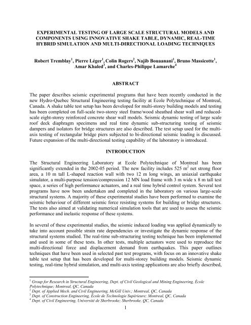
1 experimental testing of large scale structural models and ... - PEER
1 experimental testing of large scale structural models and ... - PEER
1 experimental testing of large scale structural models and ... - PEER

You also want an ePaper? Increase the reach of your titles
YUMPU automatically turns print PDFs into web optimized ePapers that Google loves.
EXPERIMENTAL TESTING OF LARGE SCALE STRUCTURAL MODELS AND<br />
COMPONENTS USING INNOVATIVE SHAKE TABLE, DYNAMIC, REAL-TIME<br />
HYBRID SIMULATION AND MULTI-DIRECTIONAL LOADING TECHNIQUES<br />
Robert Tremblay 1 , Pierre Léger 1 , Colin Rogers 2 , Najib Bouaanani 1 , Bruno Massicotte 1 ,<br />
Amar Khaled 3 , <strong>and</strong> Charles-Philippe Lamarche 4<br />
ABSTRACT<br />
The paper describes seismic <strong>experimental</strong> programs that have been recently conducted in the<br />
new Hydro-Quebec Structural Engineering <strong>testing</strong> facility at Ecole Polytechnique <strong>of</strong> Montreal,<br />
Canada. A shake table test setup has been developed for multi-storey building <strong>models</strong> <strong>and</strong> <strong>testing</strong><br />
has been completed on full-<strong>scale</strong> two-storey steel frame/wood sheathed shear wall <strong>and</strong> reduced<strong>scale</strong><br />
eight-storey reinforced concrete shear wall <strong>models</strong>. Seismic dynamic <strong>testing</strong> <strong>of</strong> <strong>large</strong> <strong>scale</strong><br />
ro<strong>of</strong> deck diaphragm specimens <strong>and</strong> real time dynamic sub-structuring <strong>testing</strong> <strong>of</strong> seismic<br />
dampers <strong>and</strong> isolators for bridge structures are also described. The test setup used for the multiaxis<br />
<strong>testing</strong> <strong>of</strong> rectangular bridge piers subjected to bi-directional seismic loading is discussed.<br />
Future expansion <strong>of</strong> the multi-directional <strong>testing</strong> capability <strong>of</strong> the laboratory is introduced.<br />
.<br />
INTRODUCTION<br />
The Structural Engineering Laboratory at Ecole Polytechnique <strong>of</strong> Montreal has been<br />
significantly extended in the 2002-05 period. The new facility includes 525 m 2 net strong floor<br />
area, a 10 m tall L-shaped reaction wall with two 12 m long wings, an uniaxial earthquake<br />
simulator, a multi-purpose tension/compression 12 MN load frame with 3 m wide x 8 m tall test<br />
space, a series <strong>of</strong> high performance actuators, <strong>and</strong> a real time hybrid control system. Several test<br />
programs have now been undertaken <strong>and</strong> completed in the laboratory on various <strong>large</strong>-<strong>scale</strong><br />
<strong>structural</strong> systems. A majority <strong>of</strong> these <strong>experimental</strong> studies have been performed to examine the<br />
seismic behaviour <strong>of</strong> different seismic force resisting systems for building or bridge structures.<br />
The tests also aimed at validating numerical simulation tools that are used to assess the seismic<br />
performance <strong>and</strong> inelastic response <strong>of</strong> these systems.<br />
In several <strong>of</strong> these <strong>experimental</strong> studies, the seismic induced loading was applied dynamically to<br />
take into account possible strain rate dependencies or investigate the dynamic response <strong>of</strong> the<br />
<strong>structural</strong> systems studied. The real-time sub-structuring <strong>testing</strong> technique has been implemented<br />
<strong>and</strong> used in some <strong>of</strong> these tests. In other tests, multiple actuators were used to reproduce the<br />
multi-directional force <strong>and</strong> displacement dem<strong>and</strong> from earthquakes. This paper outlines<br />
techniques that have been used in selected past test programs, with focus on an innovative shake<br />
table test setup that has been developed for multi-storey building <strong>models</strong>. Seismic dynamic<br />
<strong>testing</strong>, real-time hybrid simulation, <strong>and</strong> multi-axis <strong>testing</strong> applications are also briefly described,<br />
1 Group for Research in Structural Engineering, Dept. <strong>of</strong> Civil Geological <strong>and</strong> Mining Engineering, École<br />
Polytechnique; Montreal, QC, Canada<br />
2 Dept. <strong>of</strong> Applied Mech. <strong>and</strong> Civil Engineering, McGill Univ.; Montreal, QC, Canada<br />
3 Dept. <strong>of</strong> Construction Engineering, École de Technologie Supérieure; Montreal, QC, Canada<br />
4 Dept. <strong>of</strong> Civil Engineering, Université de Sherbrooke; Sherbrooke, QC, Canada<br />
1
<strong>and</strong> an overview <strong>of</strong> a new multi-directional <strong>structural</strong> component hybrid <strong>testing</strong> system to be<br />
implemented in the near future is given.<br />
SHAKE TABLE TEST SETUP FOR MULTI-STOREY BUILDINGS<br />
The uniaxial earthquake simulator has a payload capacity <strong>of</strong> 15 tons <strong>and</strong> 3.4 m x 3.4 m plan<br />
dimensions. The multi-cellular shake table box is mounted on four frictionless linear hydrostatic<br />
bearings. The bearings are designed with high vertical capacity resulting in a <strong>large</strong> overturning<br />
moment capacity for the table. The system features a fully digital MTS 469 three-variable<br />
control system with delta pressure stabilization, amplitude phase control, online iteration, <strong>and</strong><br />
adaptive inverse control capabilities. The actuator is powered by a hydraulic power supply with a<br />
total flow capacity <strong>of</strong> 1400 l/min. The frequency range is 0-50 Hz <strong>and</strong> the system can achieve<br />
peak displacements <strong>of</strong> ± 125 mm, peak velocities <strong>of</strong> 1.0 m/s <strong>and</strong> peak accelerations ranging<br />
between 3.0 g (table empty) <strong>and</strong> 1.0 g (at full payload capacity). The earthquake simulator is<br />
serviced by a 15 ton overhead crane <strong>and</strong> the vertical clearance between the test platform <strong>and</strong> the<br />
crane hook is 11 m. The <strong>large</strong> overturning moment capacity <strong>and</strong> test height clearance <strong>of</strong> this<br />
facility represents very suitable conditions for <strong>testing</strong> tall two-dimensional <strong>structural</strong> systems<br />
such as braced frame or shear wall systems.<br />
Tremblay et al. (2005) presented a preliminary study on the design <strong>of</strong> test setup for the shake<br />
table <strong>testing</strong> <strong>of</strong> seismic force resisting systems used in multi-storey building structures. The<br />
system was originally designed with a 10 m height to accommodate reduced <strong>scale</strong> <strong>models</strong> <strong>of</strong><br />
structures up to 10 storeys in height. It includes a lumped mass system that simulates the<br />
tributary seismic floor weights at every level <strong>of</strong> the <strong>structural</strong> system studied. The masses are<br />
vertically supported by columns that are independent <strong>of</strong> the test structure, simulating the gravity<br />
load frame typically found in actual buildings <strong>and</strong> allowing P-Δ effects to be taken into account<br />
in tests. The number <strong>of</strong> floors <strong>and</strong> storey heights can be easily modified to reproduce the<br />
prototype building geometry. Final design <strong>and</strong> fabrication <strong>of</strong> the setup has since been completed<br />
<strong>and</strong>, at the time <strong>of</strong> writing, the system has been used for tests on a <strong>scale</strong>d model <strong>of</strong> an 8-storey<br />
reinforced concrete shear wall <strong>and</strong> full-<strong>scale</strong> tests <strong>of</strong> single- <strong>and</strong> two-storey steel frame/wood<br />
sheathed shear wall specimens. Details <strong>of</strong> the <strong>experimental</strong> setup are presented for the 8-storey<br />
shear wall tests <strong>and</strong> the modified configuration used for the 2-storey shear wall is then presented.<br />
Testing <strong>of</strong> Reinforced Concrete Shear Walls<br />
A research project has been undertaken to better characterizing the contribution <strong>of</strong> the higher<br />
modes <strong>of</strong> vibration on the bending moment <strong>and</strong> shear force dem<strong>and</strong> on cantilevered reinforced<br />
concrete shear walls. The work focuses on slender walls located in eastern North America, where<br />
earthquakes are expected to develop ground motions richer in high frequencies, a situation where<br />
higher mode effects can be significant <strong>and</strong> induce flexural plastic hinges in the upper levels as<br />
well as excessive shear force dem<strong>and</strong>. Shake table <strong>testing</strong> was incorporated in the project to<br />
validate the numerical solutions obtained from various predictive <strong>models</strong> (Ghorbanirenani et al.<br />
2008). An 8-storey prototype residential building located on a class C site in Montreal, Quebec,<br />
was selected for this <strong>experimental</strong> study. The total height <strong>of</strong> the building is 20.97 m (8 storeys x<br />
2.621 m) <strong>and</strong> a 9 m tall wall specimen with a length scaling factor l r = 0.429 was designed for<br />
the tests. The artificial mass simulation procedure was used to develop the similitude<br />
requirements. The method was modified to introduce a scaling factor on acceleration, a r = 2.65,<br />
such that the entire tributary seismic weight <strong>of</strong> the wall studied could be included in the test<br />
2
setup. This resulted in scaling factor on time, t r = 0.403. Further information on the design <strong>and</strong><br />
numerical simulations <strong>of</strong> the test specimen can be found in Tremblay et al. (2008).<br />
Figure 1a shows a schematic <strong>of</strong> the test specimen mounted on the shake table. The wall has a<br />
rectangular cross section with uniform thickness <strong>of</strong> 80 mm <strong>and</strong> a change in width at the 6 th level.<br />
The wall specimen was constructed in the vertical position, with one-storey lifts that were poured<br />
in sequence to replicate actual construction practice. The storey height in the model is 1125 mm<br />
<strong>and</strong> the total weight <strong>of</strong> the wall, W w = 52 kN, including the weight <strong>of</strong> the base footing (11 kN).<br />
At each level, the seismic weight tributary to the wall studied is simulated by rectangular steel<br />
plates that are supported on steel columns. This seismic weight system also reproduces the<br />
gravity load carrying system that is laterally braced the shear wall. In order to free up the<br />
capacity <strong>of</strong> the linear bearings supporting the shake table to maximise the overturning moment<br />
dem<strong>and</strong> on the test specimen, the seismic weight/gravity load system is constructed on the<br />
laboratory strong floor, beside the shake table. This configuration allows seismic weight much<br />
<strong>large</strong>r than the 15 ton (145 kN) payload capacity <strong>of</strong> the table: the steel plates weigh<br />
approximately 62 kN per floor, resulting in a total gravity load W g = 500 kN for the 8 floors.<br />
(a)<br />
Wall<br />
Specimen<br />
Load Cell<br />
(typ.)<br />
Pin<br />
(typ.)<br />
Steel Plates<br />
(typ.) Wall<br />
(b)<br />
Tendon<br />
Strut<br />
(typ.)<br />
Column<br />
(typ.)<br />
Rocker<br />
(typ.) P<br />
1200<br />
1125<br />
(typ.)<br />
1400<br />
Rollers<br />
Seismic Weight/Gravity<br />
Load System<br />
Strong<br />
Floor<br />
Fig. 1. (a) Test specimen <strong>and</strong> seismic weight/gravity load system; (b) Complete test setup<br />
with stabilizing steel frame.<br />
The four steel column segments supporting the seismic weight steel plates between each floor are<br />
built with carefully machined cap plates at their upper <strong>and</strong> lower ends. Cylindrical rockers are<br />
inserted between the seismic weight steel plates <strong>and</strong> the columns ends such that the gravity load<br />
system has no lateral strength <strong>and</strong> stiffness <strong>and</strong> lateral loads <strong>and</strong> P-Δ effects are entirely resisted<br />
by the test specimen. In the transverse direction, diagonal bracing is inserted between the<br />
columns to ensure out-<strong>of</strong>-plane stability. At all floors, horizontal steel struts with high axial<br />
stiffness link the floor masses to the test specimen. The struts are connected to 300 mm wide x<br />
80 mm thick slab extensions cast on each side <strong>of</strong> the wall to mimic the horizontal shear transfer<br />
3
mechanism that prevails between the floor diaphragms <strong>and</strong> the wall in actual constructions. Load<br />
cells were introduced between the struts <strong>and</strong> the test specimen to monitor the floor inertia forces<br />
developing during the tests. At the base <strong>of</strong> the gravity load system, the steel columns are pinsupported<br />
to longitudinal horizontal steel members that extend up to the earthquake simulator to<br />
which they are connected. Those members are vertically mounted on frictionless roller bearings<br />
that roll on polished <strong>and</strong> levelled high strength steel plates placed on the laboratory strong floor.<br />
Hence, the base <strong>of</strong> the gravity system experiences the same horizontal displacement as the<br />
earthquake simulator <strong>and</strong> the test specimen is subjected to P-Δ forces induced by the lateral<br />
displacements <strong>of</strong> the specimen relative to the ground, as is the case in actual buildings. The<br />
weight <strong>of</strong> the movable horizontal base frame W b = 11 kN. The total weight carried by the four<br />
roller bearing units was therefore equal to 511 kN. An axial load P 0 corresponding to 1.5% <strong>of</strong><br />
Acf’c was applied to the wall by means <strong>of</strong> pre-tensioned tendons. A coil spring system was used to<br />
anchor the tendons at the wall top to minimize variation <strong>of</strong> the axial load during the tests.<br />
The test specimen <strong>and</strong> seismic weight/gravity system are enclosed in a braced steel frame that<br />
provides for the out-<strong>of</strong>-plane stability <strong>of</strong> the test specimen <strong>and</strong> prevents collapse <strong>of</strong> the whole test<br />
assembly in case <strong>of</strong> failure <strong>of</strong> the test specimen. Figures 1b <strong>and</strong> 2a show the entire test setup<br />
including the stabilizing steel frame. In Figure 2a, a second shear wall test specimen is being<br />
prepared next to the steel frame. The floor slab segments cast on each side <strong>of</strong> the wall can be<br />
seen in this figure. Out-<strong>of</strong>-plane lateral support <strong>of</strong> the test specimen is provided by four vertical<br />
steel shapes that are mounted on the steel frame <strong>and</strong> carefully aligned next to edges <strong>of</strong> the<br />
specimen floor slabs. Teflon material was placed between these steel shapes <strong>and</strong> the slab edges<br />
to minimize friction during the tests. The steel frame also includes working platforms that ease<br />
access to the test specimen for the instrumentation <strong>and</strong> observation during the tests.<br />
(a)<br />
(b)<br />
1.05<br />
1.00<br />
P / P 0<br />
-0.08<br />
0.95<br />
0.04<br />
Fr / W 0.00<br />
-0.04<br />
0.08<br />
F 6 / W 0.00<br />
0.3<br />
V / W 0.0<br />
-0.3<br />
0.4<br />
0.2<br />
u r,8 / hn 0.0<br />
-0.2<br />
-0.4<br />
30<br />
10<br />
20<br />
u g (mm)<br />
-10 0<br />
-20<br />
-30<br />
1.0<br />
0.5<br />
a g (g) 0.0<br />
-0.5<br />
-1.0<br />
0 5 10 15 20<br />
Time (s)<br />
Fig. 2. (a) Shake table test setup upon assembling the seismic weight at the 8 th level<br />
(a second test specimen is placed next to the test setup); (b) Time history response under<br />
the design base ground motion (model <strong>scale</strong>).<br />
4
The structure was subjected to a simulated seismic time history corresponding to an M7.0 event<br />
at 70 km in Montreal. The signal was modified to match the elastic code design spectrum used in<br />
the design <strong>of</strong> the specimen. Several tests were performed by increasing each time the amplitude<br />
<strong>of</strong> the motion. Figure 2b shows the applied ground motion acceleration <strong>and</strong> displacement time<br />
histories, a g <strong>and</strong> u g , as well as selected response parameters for the test performed under the<br />
design base earthquake level: the relative displacement at the 8 th level normalized to the<br />
specimen height, u r,8 /h n , the base shear V normalized to the total seismic weight W = 541 kN, the<br />
inertia load at the 6 th floor, F 6 , the total horizontal friction force at the base <strong>of</strong> the roller bearings,<br />
F r , as normalized with respect to the total weight supported (511 kN), <strong>and</strong> the axial load in the<br />
wall, P, normalized to the value applied at the beginning <strong>of</strong> the test, P 0 . The periods <strong>of</strong> the wall<br />
specimen in the first three modes <strong>of</strong> vibration, as measured prior to this test, are 0.76, 0.18, <strong>and</strong><br />
0.093 s. The fundamental mode <strong>of</strong> vibration dominated the top horizontal displacement response,<br />
although second mode effects can be observed in the figure. Elongation <strong>of</strong> the first mode period<br />
can also be noticed in the <strong>large</strong> amplitude cycles (T 1 becomes longer than 1.0 s). Conversely,<br />
shear <strong>and</strong> inertia forces were governed by higher mode response <strong>and</strong> plastic hinges were<br />
observed at the wall base as well at the 6 th level, as predicted by analysis. During the test, the<br />
friction force F r remained very small, less than 3% <strong>of</strong> the total supported weight, indicating that<br />
a very small portion <strong>of</strong> the actuator load was lost in friction. The tendon/coil spring assembly<br />
also proved very effective in maintaining the axial load constant during the test.<br />
Testing <strong>of</strong> Cold-Formed Steel Frame/Wood Sheathed Shear Walls<br />
A research program that aims at developing appropriate detailing <strong>and</strong> proven seismic design<br />
methods for strap braced walls wood as well as steel sheathed shear walls constructed with coldformed<br />
steel members has been undertaken at McGill University. Testing <strong>of</strong> single-storey<br />
specimens under monotonic <strong>and</strong> reversed cyclic loading has been performed in previous stages<br />
to propose shear resistance <strong>and</strong> stiffness values <strong>and</strong> tentative seismic force modification factors<br />
(Branston et al. 2006; Boudreault et al. 2007). Nonlinear time history dynamic analyses were<br />
performed to validate the proposed seismic design procedure for multi-storey applications.<br />
5
(a)<br />
(b)<br />
30<br />
2 nd storey<br />
Wall resistance (Inertia force, 2nd floor) (kN)<br />
20<br />
10<br />
0<br />
-10<br />
-20<br />
-30<br />
-120 -80 -40 0 40 80 120<br />
Drift (mm)<br />
40<br />
Wall resistance (Inertia force, 1st floor) (kN)<br />
30<br />
20<br />
10<br />
0<br />
-10<br />
-20<br />
-30<br />
1 st storey<br />
-40<br />
Fig. 3. Shake table <strong>testing</strong> <strong>of</strong> cold-formed steel frame/wood sheathed shear walls: (a) Twostorey<br />
specimen in the test setup; (b) Measured storey hysteretic responses under strong<br />
ground motion.<br />
Shake table <strong>testing</strong> <strong>of</strong> one- <strong>and</strong> two-storey shear walls made <strong>of</strong> plywood sheeting screwed to<br />
cold-formed steel stud <strong>and</strong> track assemblies has been initiated to validate <strong>and</strong> improve the<br />
numerical predictions <strong>and</strong> verify the overall inelastic performance under seismic base excitation;<br />
especially to identify whether the multi-storey wall systems are physically capable <strong>of</strong> resisting<br />
earthquake loads without significant s<strong>of</strong>t storey effects. Information on the periods <strong>of</strong> vibration<br />
was also needed for these cold-formed steel framed lateral systems. A variant <strong>of</strong> the seismic<br />
weight/gravity load system described earlier was used in these shake table tests. In particular, the<br />
wall height was increased to 2.44 m with an additional 0.3 m thick floor structure. The seismic<br />
weight was reduced to 30 kN per floor to represent the force level associated with this type <strong>of</strong><br />
lateral framing system. Figure 3a shows a two-storey shear wall specimen (1.22 x 2.44 m wall<br />
segments) in the test setup. Figure 3b compares the storey shear-storey drift hysteretic response<br />
recorded at each level under strong ground shaking. The graphs show the complex pinched <strong>and</strong><br />
degrading inelastic behaviour exhibited by these wall assemblies. The tendency for concentration<br />
<strong>of</strong> the inelastic dem<strong>and</strong> in the top floor, due to a more sparse sheathing connection pattern<br />
compared with the ground floor wall, can also be clearly observed in this particular test.<br />
Future Shake Table Test Programs<br />
The performance <strong>of</strong> repair <strong>and</strong> strengthening schemes for reinforced concrete shear walls will be<br />
examined in future shake table tests. Shake table experiments on cold-formed steel shear walls<br />
(with either wood or steel sheathing) <strong>and</strong> braced frames will continue with tests performed on<br />
full-<strong>scale</strong> three storey buildings. It is also planned to use the shake table test setup for the study<br />
6<br />
-120 -80 -40 0 40 80 120<br />
Drift (mm)
<strong>of</strong> innovative braced steel frame systems including dual systems incorporating elastic framing<br />
components that are specifically designed to minimize inelastic dem<strong>and</strong> concentration over the<br />
structure height or systems that feature rocking or self-centring capabilities.<br />
DYNAMIC TESTING OF STEEL ROOF DIAPHRAGMS<br />
Dynamic seismic <strong>testing</strong> was completed on <strong>large</strong> size diaphragms built with corrugated steel<br />
deck panels as used in the ro<strong>of</strong> <strong>of</strong> single-storey steel buildings. Figure 4a shows a schematic <strong>of</strong><br />
the 21 m x 7.3 m rectangular test specimen: the steel deck sheets are installed on a horizontal<br />
steel beam <strong>and</strong> joist assembly replicating typical ro<strong>of</strong> <strong>structural</strong> framework. The steel deck sheets<br />
are fastened to each other along their edges as well as to the supporting steel structure to develop<br />
diaphragm behaviour. The test frame was mounted horizontally on rockers seating on the<br />
laboratory strong floor <strong>and</strong> in-plane loading was dynamically applied using two 1000 kN high<br />
performance actuators acting in phase at either end <strong>of</strong> the test specimen.<br />
(a)<br />
7310<br />
12 @ 1751.6 = 21 020<br />
6400 7310<br />
(b)<br />
W360x39<br />
8 @ 914 = 7310<br />
1000 kN<br />
Dynamic<br />
Actuator<br />
(typ.)<br />
W360x39 with<br />
HSS 101.6x101.6x4.8<br />
Shear Connectors<br />
(typ.)<br />
450mm<br />
Joists<br />
(typ.)<br />
Fig. 4. Dynamic seismic <strong>testing</strong> <strong>of</strong> steel deck ro<strong>of</strong> diaphragms: (a) Test setup (deck sheets<br />
perpendicular to in-plane loading shown); (b) Construction <strong>of</strong> a test specimen.<br />
This loading system reproduced the ground motion effects as transmitted at the ro<strong>of</strong> level by the<br />
vertical framing elements in actual building structures. Several specimens were tested to examine<br />
the influence <strong>of</strong> the deck sheet thickness <strong>and</strong> fastener type <strong>and</strong> spacing. The effect <strong>of</strong> varying the<br />
amplitude <strong>of</strong> loading on the in-plane diaphragm shear stiffness <strong>and</strong> periods <strong>of</strong> vibration was also<br />
investigated. Inelastic response under strong seismic ground motions typically developed in the<br />
connectors <strong>and</strong> by tearing or local buckling <strong>of</strong> the sheet material in the vicinity <strong>of</strong> the connectors.<br />
The <strong>large</strong> dimensions <strong>of</strong> the test specimens permitted to study the distribution <strong>and</strong> amplitude <strong>of</strong><br />
this inelastic dem<strong>and</strong> over the diaphragm. The impact on elastic <strong>and</strong> inelastic diaphragm<br />
responses <strong>of</strong> the end lap joints that exist between deck sheets could also be studied in the test<br />
program.<br />
7
REAL-TIME DYNAMIC SUB-STRUCTURING TESTING<br />
The MTS 469 digital controller <strong>of</strong> the shake table has been upgraded to include the capability <strong>of</strong><br />
performing either seismic <strong>testing</strong> or real-time <strong>structural</strong> hybrid <strong>testing</strong>. When used for hybrid<br />
<strong>testing</strong>, the system is capable <strong>of</strong> running up to five <strong>structural</strong> actuators simultaneously under a<br />
common single test configuration, including the 12 MN load frame. The system includes three<br />
computers to allow real time execution between Matlab/Simulink® <strong>models</strong> <strong>and</strong> the MTS servocontroller:<br />
one computer where Simulink <strong>models</strong> are developed <strong>and</strong> hosted, one computer used<br />
as a secondary target computer where Simulink programs are efficiently run using the<br />
MathWorks xPC Target operating s<strong>of</strong>tware, <strong>and</strong> one computer used for the MTS controller.<br />
Shared memory via Systran’s ScramNet® capabilities are used to pass comm<strong>and</strong> <strong>and</strong> feedback<br />
signals simultaneously to all computer nodes. A schematic <strong>of</strong> the control configuration is<br />
illustrated in Fig. 4a for hybrid <strong>testing</strong> <strong>of</strong> a structure equipped with seismic dampers.<br />
(a)<br />
(b)<br />
(c)<br />
Displacement (mm)<br />
15<br />
10<br />
5<br />
0<br />
-5<br />
-10<br />
-15<br />
M6.0 at 30 km<br />
RTDS Test<br />
Analysis<br />
0 1 2 3 4 5 6 7 8<br />
Time (s)<br />
Fig. 5. Hybrid simulation <strong>of</strong> an isolated bridge structure: (a) Test configuration; (b)<br />
Damper physically tested in the laboratory; (c) Comparison <strong>of</strong> the bridge response under<br />
M6.0 at 30 km ground motion from RTDS <strong>and</strong> numerical simulations.<br />
In the last two years, efforts have been directed towards the development <strong>of</strong> a Rosenbrock-W<br />
semi-implicit integration scheme that can be used in real time dynamic sub-structuring (RTDS)<br />
<strong>and</strong> pseudo-dynamic (PSD) <strong>testing</strong> applications (Lamarche et al. 2009). The algorithm has been<br />
implemented <strong>and</strong> validated by comparing against shake table tests conducted on a two-storey<br />
steel frame model (Lamarche et al. 2008). The system has been recently used with success for<br />
the full-<strong>scale</strong> <strong>testing</strong> <strong>of</strong> various strain rate dependant seismic isolators <strong>and</strong> dampers for bridge<br />
structures. The main objective <strong>of</strong> that project was to assess the capacity to predict the response <strong>of</strong><br />
bridge structures using commercially available computer programs. Real time hybrid simulations<br />
have been carried with the dampers physically tested in the laboratory. Figure 5b illustrates such<br />
8
a physical test being carried out using a 1500 kN dynamic actuator. Figure 5c compares the<br />
response determined from a purely numerical simulation to that obtained from the hybrid test for<br />
a bridge equipped with nonlinear viscous dampers. In that particular case, the test confirmed that<br />
the analysis s<strong>of</strong>tware could be used efficiently to assess the seismic displacement dem<strong>and</strong><br />
imposed on the bridge.<br />
MULTI-AXIS TESTING<br />
Multi-Axial Testing <strong>of</strong> Reinforced Concrete Bridge Columns<br />
Multi-directional loading has been performed on half-<strong>scale</strong> bridge columns with rectangular<br />
cross-section using the 10 m tall, L-shaped reaction wall <strong>of</strong> the laboratory <strong>and</strong> five high<br />
performance <strong>structural</strong> actuators, as illustrated in Fig. 6. The objective <strong>of</strong> the test program was to<br />
validate seismic design requirements for bi-directional seismic loading, with special interest in<br />
the difference in the dem<strong>and</strong> anticipated from earthquakes expected in eastern <strong>and</strong> western<br />
regions <strong>of</strong> North America (Khaled et al. 2006).<br />
In the test setup, constant gravity load was applied using a transverse horizontal beam <strong>and</strong> two<br />
vertical 1000 kN actuators symmetrically located on either side <strong>of</strong> the test specimen. One <strong>of</strong><br />
these two actuators was controlled in the displacement mode to maintain the position <strong>of</strong> the beam<br />
whereas the other one was load controlled to impose the required axial compression load in the<br />
column. The target displacement time histories along the three horizontal degrees <strong>of</strong> freedom at<br />
the column top were imposed by means <strong>of</strong> three horizontal actuators. In that particular test<br />
program, in-plane torsional rotation was kept equal to zero such that the response under the<br />
combination <strong>of</strong> the bending moments about both principal directions as determined from<br />
previous time history analysis could be examined.<br />
Fig. 6. Testing <strong>of</strong> a 1:0.5 rectangular bridge column under bi-directional seismic loading.<br />
9
New Multi-Directional Hybrid Testing System<br />
Ecole Polytechnique <strong>of</strong> Montreal has recently been awarded a major equipment grant for the<br />
acquisition <strong>of</strong> a high performance multi-directional <strong>structural</strong> component hybrid <strong>testing</strong> system<br />
that will be used in combination with the existing L-shaped reaction wall. The system is designed<br />
to apply any combination <strong>of</strong> forces or deformations along 6 degrees <strong>of</strong> freedom at the top end <strong>of</strong><br />
the test specimen, resulting in a combination <strong>of</strong> axial load, torsional moment, bi-axial bending<br />
moments <strong>and</strong> bi-axial shear forces applied to the specimen. As shown in Fig. 7a, a total <strong>of</strong> eight<br />
<strong>structural</strong> actuators are used in combination with one moment platen. The base <strong>of</strong> the test<br />
specimen is anchored to the strong floor <strong>of</strong> the <strong>structural</strong> laboratory <strong>and</strong> the upper part is secured<br />
to the underside <strong>of</strong> the moment platen. The system has also been designed to be mounted within<br />
the existing 12 MN load frame to take advantage <strong>of</strong> the <strong>large</strong> axial load capacity <strong>of</strong> the test frame<br />
(Fig. 7b). In this configuration, 4 vertical actuators are used in combination with 2 moment<br />
platens such that any combination <strong>of</strong> end bi-axial moments can be applied together with high<br />
axial compression force. Free rotation <strong>of</strong> the upper platen relative to the load frame cross-head is<br />
achieved by means <strong>of</strong> a pressure balanced bearing unit. Reaction frames will be used to prevent<br />
the horizontal displacements <strong>and</strong> torsional movements <strong>of</strong> the upper moment platen (not shown in<br />
the figure). The project also includes an upgrade <strong>of</strong> the existing shake table actuator to enhance<br />
the capacity <strong>of</strong> the test setup described earlier.<br />
a)<br />
M X<br />
T Z<br />
b)<br />
P<br />
M Y<br />
V X<br />
V Y<br />
P<br />
M X<br />
M Y<br />
Fig. 7. Proposed multi-directional hybrid system configurations: (a) With the L-shaped<br />
reaction wall; (b) Within the 12 MN load frame (lateral reaction frames not shown).<br />
CONCLUSIONS<br />
Nonlinear time history dynamic analysis has become common practice to study the inelastic<br />
seismic response <strong>of</strong> <strong>structural</strong> systems <strong>and</strong> to assess their seismic performance. This analytical<br />
procedure has been demonstrated to adequately predict the behaviour <strong>of</strong> seismic force resisting<br />
systems that have well defined inelastic mechanisms with stable hysteretic response, such as<br />
beam flexural hinging or axial buckling <strong>and</strong> yielding, when subjected to limited inelastic<br />
dem<strong>and</strong>. The analysis <strong>of</strong> <strong>structural</strong> systems that involve severe strength <strong>and</strong> stiffness degradation,<br />
strain rate dependency, complex interaction between various <strong>structural</strong> components or multiple<br />
10
load paths with different response characteristics still represents a challenge that requires careful<br />
<strong>experimental</strong> validation. Physical <strong>testing</strong> is also required to verify the capacity <strong>of</strong> <strong>structural</strong><br />
system to resist against partial or total collapse.<br />
This paper presented various <strong>experimental</strong> techniques that have been recently implemented <strong>and</strong><br />
used at the new <strong>testing</strong> facility at Ecole Polytechnique <strong>of</strong> Montreal. Test programs devoted to the<br />
study the seismic response <strong>of</strong> <strong>structural</strong> systems subjected to dynamically applied or multidirectional<br />
seismic loading were presented <strong>and</strong> discussed. In particular, a versatile test setup has<br />
been developed to study the response <strong>of</strong> seismic force resisting systems used in multi-storey<br />
buildings. The system can be easily reconfigured to accommodate different <strong>structural</strong> systems<br />
with different heights, number <strong>of</strong> floors <strong>and</strong> seismic weights. The system also allows for P-Δ<br />
effects to be taken into account <strong>and</strong> is therefore suitable for global seismic stability response<br />
evaluation. Dynamic seismic tests <strong>of</strong> <strong>large</strong> <strong>scale</strong> ro<strong>of</strong> deck diaphragms <strong>and</strong> real time substructure<br />
simulations <strong>of</strong> bridge structures equipped with highly nonlinear <strong>and</strong> strain rate<br />
dependant seismic isolator <strong>and</strong> damping systems were carried using high performance dynamic<br />
actuators. Testing <strong>of</strong> <strong>large</strong> <strong>scale</strong> columns under combined gravity load <strong>and</strong> bi-directional loading<br />
has been completed. Future expansion <strong>of</strong> the <strong>testing</strong> facility includes the addition <strong>of</strong> a multi-axis<br />
<strong>testing</strong> system for hybrid simulations <strong>and</strong> an upgrade <strong>of</strong> the actuator capacity <strong>of</strong> the shake table.<br />
ACKNOWLEDGEMENTS<br />
Funding for the construction <strong>of</strong> the <strong>testing</strong> laboratory was provided by the Canadian Foundation<br />
for Innovation, the Government <strong>of</strong> Quebec, Hydro-Quebec, SNC-Lavalin, Cima+, Aciers<br />
Gendron, the Canam Group, Dywidag International, MTS Systems, <strong>and</strong> Ecole Polytechnique <strong>of</strong><br />
Montreal. The research projects presented in the paper were financially supported by the Fonds<br />
Québécois de la recherche sur la nature et les technologies (FQRNT) <strong>of</strong> the Province <strong>of</strong> Quebec,<br />
the Natural Sciences <strong>and</strong> Engineering Research Council (NSERC) <strong>of</strong> Canada <strong>and</strong> several<br />
industrial partners <strong>of</strong> which the Ministry <strong>of</strong> Transportation <strong>of</strong> Quebec, the Canadian Institute <strong>of</strong><br />
Steel Construction, the Canadian Sheet Steel Building Institute, the Steel Deck Institute, the<br />
Canam Group, Hilti Canada, the WSB group, Read Jones Christ<strong>of</strong>fersen, <strong>and</strong> LCL-Bridge<br />
Products Technology. The contribution <strong>of</strong> Graduate Research Assistants Iman Ghorbanirenani,<br />
Cass<strong>and</strong>ra Dion, <strong>and</strong> Iman Shamim for assistance in the preparation <strong>of</strong> figures presented in the<br />
paper is acknowledged.<br />
REFERENCES<br />
Boudreault, F.A., Blais, C., Rogers, C.A. 2007. Seismic force modification factors for lightgauge<br />
steel-frame – wood <strong>structural</strong> panel shear walls. Can. J. Civ. Eng., 34(1), 56-65.<br />
Branston, A.E., Chen, C.Y., Boudreault, F.A., Rogers, C.A. 2006. Testing <strong>of</strong> light-gauge steelframe<br />
– wood <strong>structural</strong> panel shear walls." Can. J. Civ. Eng., 33(5), 561-572.<br />
Ghorbanirenani, I., Tremblay, R., Léger, P., <strong>and</strong> Palermo, D. 2008. Inelastic Seismic Evaluation<br />
<strong>of</strong> Slender Shear Walls Designed According to CSA-A23.3-04 <strong>and</strong> NBCC 2005. Proc. CSCE<br />
2008 Annual Conference, Quebec, QC, Paper No. 520.<br />
Khaled, A., Tremblay, R., <strong>and</strong> Massicotte, B. 2006. Assessing the adequacy <strong>of</strong> the 30%<br />
combination rule in estimating the critical response <strong>of</strong> bridge piers under multi-directional<br />
earthquake components. Proc. 7 th Int. Conf. on Short <strong>and</strong> Medium Span Bridges, Montreal,<br />
QC, Paper SD-014.<br />
Lamarche, C.-P., Bonelli, A., Bursi, O., <strong>and</strong> Tremblay, R. 2009. A Rosenbrock-W method for<br />
11
eal time sub-structuring <strong>and</strong> PSD <strong>testing</strong>. Earthquake Engineering <strong>and</strong> Structural Dynamics,<br />
38(9): 1071-1092.<br />
Lamarche, C.-P., Leclerc, M., Tremblay, R., Léger, P., Bouaanani, N., Koboevic, S., <strong>and</strong> Bursi,<br />
O. 2008. Comparison between real time nonlinear seismic hybrid <strong>and</strong> shake table <strong>testing</strong><br />
techniques. Proc. 14th World Conf. on Earthquake Eng., Beijing, China, Paper No. 12-01-<br />
0236.<br />
Tremblay, R., Velev, N., Merzouq, S., Blais, C., Leclerc, M., Léger, P., Massicotte, B., <strong>and</strong><br />
Rogers, C. 2005. Multi-Purpose Earthquake Simulation Testing Set-Up for Seismic Force<br />
Resisting Systems <strong>of</strong> Multi-Story Buildings. Proc. First Int. Conf. on Advances in<br />
Experimental Structural Eng., Nagoya, Japan, Paper No. 533.<br />
Tremblay, R., Ghorbanirenani, I., Velev, N., Léger, P., Leclerc, Koboevic, S., Bouaanani, N.,<br />
Galal, K., <strong>and</strong> Palermo, D. 2008. Seismic Response <strong>of</strong> Multi-Storey Reinforced Concrete<br />
Walls Subjected to Eastern North America High Frequency Ground Motions. Proc. 14th<br />
World Conf. on Earthquake Eng., Beijing, China, Paper No. 05-01-0526.<br />
Tremblay, R., Rogers, C., Lamarche, C.-P., Nedisan, C., Franquet, J., Masarelli, R., <strong>and</strong><br />
Shrestha, K. 2008. Dynamic Seismic Testing <strong>of</strong> Large Size Steel Deck Diaphragm Low-Rise<br />
Building Applications. Proc. 14th World Conf. on Earthquake Eng., Beijing, China, Paper<br />
No. 05-05-0066.<br />
12